1
Allgemeiner Teil / General Section
GDV 100 D/002
Es gelten die Vorschriften und Sicherheitshinweise
gemäß dem Service Manual "Sicherheit", Materialnummer 72010 800 0000, sowie zusätzlich die eventuell abweichenden, landesspezifischen Vorschriften!
The regulations and safety instructions shall be valid
as provided by the "Safety" Service Manual, part
number 72010 800 0000, as well as the respective
national deviations.
Dieses Service Manual gilt nur für das Gerät GDV 100 D/002
(Bezeichnung siehe Typenschild!). Für das Gerät GDV 100 D (ohne
/002) verwenden Sie bitte ausschließlich das Service Manual mit
der Materialnummer 72010 531 9500.
D
This Service Manual is valid only for the GDV 100 D /002
(Designation see product label!). For the GDV 100 D (without /002)
please use exclusively the Service Manual with the part number
72010 531 9500.
GB
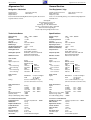
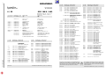
Inhaltsverzeichnis
Table of Contents
Seite
Allgemeiner Teil ................................ 1-3…1-15
Page
General Section ................................. 1-3…1-22
Meßgeräte / Meßmittel ................................................................
Technische Daten .......................................................................
Ausbauhinweise ..........................................................................
Servicehinweise ..........................................................................
Bedienhinweise ...........................................................................
1-3
1-3
1-4
1-7
1-9
Test Equipment / Jigs ................................................................. 1-3
Specifications .............................................................................. 1-3
Disassemly Instructions .............................................................. 1-4
Service Instructions ..................................................................... 1-7
Operating Hints ......................................................................... 1-16
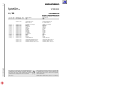
Beschreibung ...................................... 2-1…2-7
Description ........................................ 2-8…2-14
Netzteil ........................................................................................
Bedieneinheit ..............................................................................
A/V-MUX-Platte ...........................................................................
Digital-Platte ................................................................................
2-1
2-2
2-3
2-3
Power Supply .............................................................................. 2-8
Keyboard Control Unit ................................................................. 2-9
A/V MUX Board ......................................................................... 2-10
Digital Board ............................................................................. 2-10
Servicetestprogramm ......................... 3-1…3-8
Service Test Programme .................. 3-9…3-16
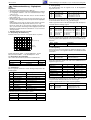
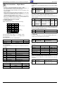
Automatischer Systemtest ..........................................................
Manueller Systemtest .................................................................
PC-Systemtest ............................................................................
Servicetestebenen ......................................................................
3-1
3-1
3-5
3-7
Automatic System Test ............................................................... 3-9
Manual System Test ................................................................... 3-9
PC System Test ........................................................................ 3-13
Service Test Levels ................................................................... 3-15
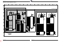
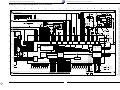
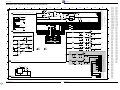
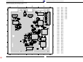
Platinenabbildungen
und Schaltpläne ................................ 4-1…4-46
Layout of the PCBs
and Circuit Diagrams ........................ 4-1…4-46
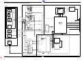
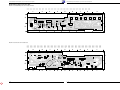
Verdrahtungsplan ........................................................................ 4-1
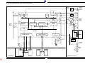
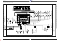
Blockschaltpläne ......................................................................... 4-3
Abkürzungen ............................................................................... 4-9
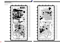
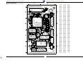
Kopfhörerplatte ......................................................................... 4-10
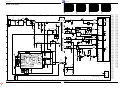
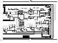
Netzteil ...................................................................................... 4-11
Bedieneinheit ............................................................................ 4-15
A/V-MUX-Platte ......................................................................... 4-19
Digitalplatte ............................................................................... 4-23
• Speicher .................................................................................. 4-25
• Prozessor und Decoder .......................................................... 4-27
• Audio- und Video-Teil ............................................................. 4-29
Laufwerk-Servoplatte ................................................................ 4-31
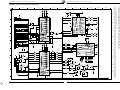
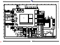
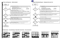
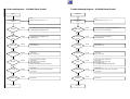
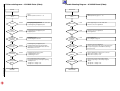
Fehlersuchdiagramme/Fehlersuchanleitung ............................. 4-41
• Netzteil ................................................................................... 4-41
• Bedieneinheit ......................................................................... 4-42
• A/V-MUX-Platte ...................................................................... 4-43
• Digitalplatte ............................................................................ 4-45
Wiring Diagram ........................................................................... 4-1
Block Circuit Diagrams ................................................................ 4-3
Abbreviations .............................................................................. 4-9
Headphone Board ..................................................................... 4-10
Power Supply ............................................................................ 4-11
Keyboard Control Unit ............................................................... 4-15
A/V MUX Board ......................................................................... 4-19
Digital Board ............................................................................. 4-23
• Memory ................................................................................... 4-25
• Processor and Decoder .......................................................... 4-27
• Audio and Video Part .............................................................. 4-29
Drive Mechanism Servo Board ................................................. 4-31
Trouble Shooting Diagram/Test Instructions ............................. 4-41
• Power Supply .......................................................................... 4-41
• Keyboard Control Unit ............................................................ 4-42
• A/V MUX Board ...................................................................... 4-43
• Digital Board ........................................................................... 4-46
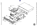
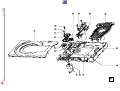
Explosionszeichnungen
und Ersatzteillisten ............................. 5-1…5-4
Exploded Views and
Spare Parts Lists ................................. 5-1…5-4
„Dolby“, „Dolby Pro Logic“, „AC 3“ ist gefertigt unter Lizenz von Dolby Laboratories
Licensing Corporation.
„Dolby“, „Dolby Pro Logic“, „AC 3“ und das Doppel-D-Symbol „ “ sind Warenzeichen der Dolby Laboratories Licensing Corporation. Copyright 1992 Dolby
Laboratories, Inc. Alle Rechte vorbehalten.
“Dolby“, “Dolby Pro Logic“, “AC 3” manufactured under license from Dolby
Laboratories Licensing Corporation.
“Dolby“, “Dolby Pro Logic“, “AC 3” and the double-D symbol “ ” are trademarks of
the Dolby Laboratories Licensing Corporation. Copyright 1992 Dolby Laboratories,
Inc. All rights reserved.
g
1-2
g
GRUNDIG Service