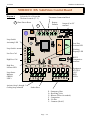
1
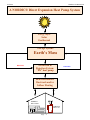
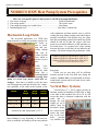
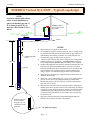
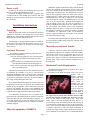
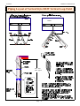
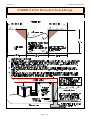
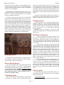
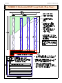
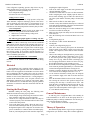
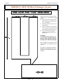
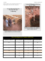
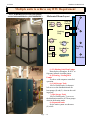
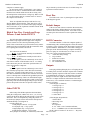
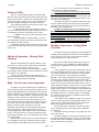
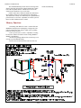
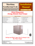
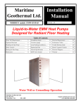
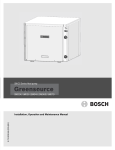
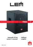
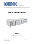
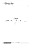
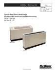
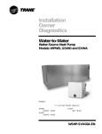
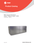
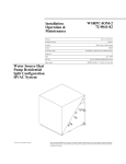
Maritime
Geothermal Ltd.
Installation
Manual
NORDIC® models DXW-45-55-65
Revision 1.1
June, 1997
DX-to-Water
Direct Expansion Heat Pumps
Table of Contents
Heat Pump System Requirements .....
3
Dimensions & Piping Layout
18
Method of Operation ………. 30
Installation Instructions
……….
7
Trouble Shooting Guide ..........
22
Warranty ...............................
Installing DX linesets ..................
9
Component Layout ................
21
Inside Installation ………………….
12
Electrical Schematic .............
25
Starting the Heat Pump …………...
13
Electrical Block Diagram .......... 24
Theory of Operation............................
15
DX Micro controller …….. 27
25
Refrigerant Filled Copper Heat Exchanger Loop
Hot Water Output
Maritime Geothermal Ltd.
P.O. Box 413
Petitcodiac, N.B.
E0A 2H0
Email: [email protected]
www.discribe.ca/nordic/mgmain.htm
12-Feb-00
Maritime Geothermal Ltd.
A NORDIC® Direct Expansion Heat Pump System
Energy Input:
Solar
Geothermal
Storage System:
Earth’s Mass
HEATING
Extraction &
Rejection System:
“DX” heat pump
Heat Distribution:
Ductwork and/or
Infloor Heating
NORDIC®
DX-to-Water
NORDIC®
DX-to-Air
Page .... 2
COOLING
Maritime Geothermal Ltd.
12-Feb-00
NORDIC® DXW Heat Pump System Prerequisites
1.
2.
3.
4.
There are four specific parts or sub-systems to a DXW heat pump installation:
The source of energy ............................................................... Solar & Geothermal
The storage media ................................................................... The Earth’s mass
Converting the energy to a useable form ................................... Heat Pump
Distributing the heat ..................................................................Hot Water / radiant slab
Horizontal Loop Fields
The successful application of a DXW heat
pump depends on sizing the machine correctly for
the home or
area to condition and providing enough
land area or
volume of earth
from which to
extract or reject
heat.
DXW
heat
pumps
react
with the earth
much like a
conventional
reversing heat
pump and closed loop plastic earth heat exchanger. Heat that is available to the unit must
travel through the earth and therefore the conduction capability of the earth in the location of the
Model
# of
Loops
Area
Req’d
Nordic DXW-45 (3) x 350’ 8,000 ft²
Trench
Layout
4’x 175’
Nordic DXW-55 (4) x 350’ 10,000 ft² 4’ x 175’
Nordic DXW-65 (5) x 350’ 12,500 ft² 4’ x 175’
Note: These are minimum loop field requirements
based on an earth temperature of 45° F.
heat exchanger is very important. A unit used entirely or primarily for heating will have no problem
with conduction and heat transfer since it will be
cooling the loop during heating mode which draws
moisture towards the coils because they are colder
than the surrounding ground. Horizontal loop fields
should be laid out so that the copper coils have
good cross-sectional influence on the minimum areas listed above. As a general rule, wider spacing
between the loops so that they do not influence one
another, will result in improved performance of the
Nordic® DXW-45 will heat up to 1500 sq. ft.
Nordic® DXW-55 will heat up to 2200 sq. ft.
Nordic® DXW-65 will heat up to 2800 sq. ft.
Assuming at least R-20 walls and R-40 ceiling
heat pump.
Unless you are sure there will be sufficient
moisture present in the loop field area during the
summer, a soaker hose is recommended in all horizontal trench systems which will used for air conditioning purposes.
Vertical Bore Systems
Vertical bores (3” x 100 ft. holes) provide an
alternate method of installing a DXW unit. A high
water table in the borehole area (20 to 30 ft.) will
insure that there is adequate conduction with the
earth and although the loop
length per ton is
shorter than the
horizontal design,
the vertical orientation and moisture in the boreholes
provides
very uniform con-
Page .... 3
12-Feb-00
Maritime Geothermal Ltd.
NORDIC® DXW Series Typical Plumbing
Page .... 4
Maritime Geothermal Ltd.
12-Feb-00
Introduction to DXW Technology
Direct earth coupled heat pump or “DXW” heat pump is
one that has its refrigerant evaporator / condenser in direct
thermal contact with the earth from which heat is either extracted from during the heating mode or introduced to during
the cooling mode of operation.
The general refrigeration cycle of our DXW machine is
similar in nature to a conventional water-to-air or water-towater heat pump in that there exist a compressor, expansion
device, reversing valve, and refrigerant-to-air heat exchanger.
Conventional technology concerned with heat pumps relies upon the transfer of heat from the ground by means of a
secondary heat exchanger system and working fluid, e.g., water, which is pumped to the geothermal unit located in the
heated structure. The conventional heat pump has it’s own
internal primary heat exchanger which extracts heat (heating
mode) or rejects heat (cooling mode) from this water, which
is then pumped back to the earth to be reheated or cooled.
DXW systems similarly use a ground coil system, however, the working fluid is a refrigerant and the copper groundloop is the primary heat exchanger. Such geothermal heat exchange is an efficient and effective way of achieving heat exchange in heating and air conditioning systems, and especially
heat pump type systems. Since the ground temperature is relatively constant at 48 oF. at a depth 6 ft. below the frost line,
the available heat is constant.
The elimination of the secondary earth heat exchanger
(typically plastic in nature) and its associated working fluid
reduces the temperature difference required between the
ground and the evaporating refrigerant yielding a higher suction pressure than a conventional system under similar circumstances and thus a higher efficiency.
Many attempts have been made in the past to develop successful direct coupled heat pumps for residential and commercial uses. These attempts have failed adequately to meet a
number of requirements associated with an economically and
functionally viable system. Some of the shortcomings included:
1. Inadequate oil return to the compressor primarily in the
heating mode.
2. Inadequate evaporator length and spacing for properly
extracting heat from the earth resulting in low capacity
and low efficiency of the systems.
3. Refrigerant charges in the range of 10 times greater than
a similar capacity conventional geothermal heat pump.
4. Approximately 3 times as much refrigerant required in
the cooling mode as is required in the heating mode.
5. Lack of a proper means to store additional refrigerant required during the cooling operation but not needed during
the heating mode.
6. Inefficient and ineffective method to account for vastly
varying condenser capability depending on ground temperature.
7. Difficulty in providing an easy to install system of earth
exchanger loops.
The NORDIC® solution has been to start with a clean
new concept and to design a unit from the ground up. We
started by developing an evaporator system that would yield
the best performance to pressure drop factor and which would
impact enough area to maintain a minimum suction pressure
above 40 Psig. The current horizontal groundloop comprises
350 ft. per ton of 1/2” OD copper tubing. A 3 ton system
would have 3 such loops working in parallel during the heating mode. Refrigerant charge had been determined to be 5 lbs.
of R-22 per loop. These 1/2” copper loops maintain sufficient
velocity at all times to insure adequate oil return. During cooling mode the machine automatically selects one or more loops
based on discharge pressure to act as the condenser. As the
discharge pressure builds to a predetermined point, the onboard computer selects the most appropriate combination of
groundloops to dissipate the heat at the lowest cost to the
homeowner. By intelligently controlling the manner in which
the condenser is utilized our total system charge does not
have to be altered nor does an excess charge have to be stored
anywhere.
DXW Better than Current Technology
There are several advantages of “DXW” technology that
are superior to conventional geothermal heat pumps of both
the “open loop” and “closed loop” variety. Listed below are
some of the reasons why “DXW” technology is becoming
more attractive to Homeowners, Dealers and Utilities.
More Reliable.
•
•
•
•
Fewer parts to the system.
Does not require a supply and return well.
Does not require a well pump or circulation pumps.
No water heat exchanger and associated valving to corrode, freeze and break.
More Efficient
The direct expansion principle allows the refrigerant to
come directly into contact with the earth, separated only by
copper tubing. During winter, maximum heat transfer takes
place at higher temperature than conventional groundloop
technology without the maintenance and electrical cost of circulation pumps.
Less Maintenance
Only a sealed refrigeration circuit to maintain.
More Versatile
“DXW” systems can be installed in a more confined area
than a conventional groundloop system, primarily because the
heat exchanger coil is much more efficient at transferring heat
to the refrigerant than a plastic earth exchanger. Normal loop
lengths for a “DXW” machine are nominally 350 ft. per ton as
opposed to 450 to 500 ft. per ton for a plastic earth exchanger.
Similarly, vertical systems require only a 3” borehole to a
normal depth of 100 ft. per ton.
Page .... 5
12-Feb-00
Maritime Geothermal Ltd.
NORDIC® Vertical Style DXW - Typical Loop design
NOTE:
Layout for one borehole shown
below. Actual installation requires one borehole per ton. (I.
E. (3) holes for a DX-45, (4)
holes for a DX-55 and (5) for a
DX-65
NORDIC® DX-toAir or DX-to-Water
Heat Pump
Liquid Line
Vapor Line
Trench
6 ft.
•
•
Insulate liquid line
to here
•
120 ft max.
•
Spacers
•
•
•
•
Pinch around pipes
and silver braze.
Keep pipes up 1/2”
off bottom to insure
good flow.
NOTES:
Drill vertical bore to a depth of 100 to 120 ft.
Pre-assemble or construct on site the dual (3/8” and 1/2”) piping assembly required. Seal both ends and pressurize with 150 psig. nitrogen for
leak checking. Silver brazing a schrader valve in the end of the 3/8”
line will allow gauge checking for loss of pressure.
Check for leaks with soap suds. After a minimum 2 hr waiting period,
recheck the line for loss of pressure. If the temperature of the loop
hasn’t changed then the pressure should be same as it was originally.
Insulate both liquid lines and vapor lines from the heat pump to the well
head unless in separate horizontal trenches. Vapor lines in separate
horizontal trenches need only be insulated from 10 ft. out in the trench
to the basement wall. Liquid lines must be insulated from the heat
pump to approx. 6 ft. down the drop pipes in the vertical boreholes.
Install spacers to keep the pipes separated as far as possible from one
another in the boreholes.
Install 100 - 120 ft. of dual tubing (1/2” vapor & 3/8” liquid). Recheck
pressure on lines. Secure pipes through opening in borehole head.
Backfill with pea gravel to 30 ft. from top. Seal hole with bentonite
clay from 30 ft. to surface.
Install linesets from well heads in horizontal trenches to heat pump in
building. Silver braze all joints with 5% silver solder using dry nitrogen
to purge the system. When all joints are complete, pressurize the entire
system with 150 psig. nitrogen and recheck for leaks. Vacuum until
system stays below 500 microns for five minutes after vacuum pump
has been shut off.
Charge the prescribed amount of refrigerant through the high side
schrader valve located on the front of the machine.
7/8” Stub Cap (Copper)
Page .... 6
Maritime Geothermal Ltd.
12-Feb-00
Easier to sell
Systems can be quoted more accurately and easily since
there is less outside subcontracting involved.
Excavation or drilling contractors know in advance what
is required and can quote definite prices whereas with well
drilling for open loop systems, the well price may eliminate
the sale entirely.
Installation Instructions
Unpacking
When the heat pump reaches it's destination it should be
unpacked to determine if any damage has occurred during
shipment. Any visible damage should be noted on the carrier's
freight bill and a suitable claim filed at once.
The heat pump is strongly constructed and every effort has
been made to insure that it will arrive intact, however, it is in
the customer's best interest to examine the unit thoroughly
when it arrives.
Optimum Placement
The location of liquid-to water heat pump inside the
home should be determined by:
1. The ease at which piping runs can be connected to the
infloor heating headers on the output side of the
unit.
2. Space availability in a mechanical room for the hot
water distribution tank and associated pumps etc.
3. Ease of access to the water well supply and discharge
lines or groundloop lines.
If possible the four main service doors should remain clear
of obstruction for a distance of (2) two ft. so that servicing
and general maintenance can be carried out with a minimum
of difficulty. Raising the heat pump off the floor a few inches
is generally a good practice since this will prevent unnecessary rusting of the bottom panel of the unit.
We recommend that the heat pump be placed on a piece of
2" Styrofoam covered with 1/4" plywood. The Styrofoam will
smooth out any irregularities in the cement floor while the
plywood will distribute the weight of the NORDIC® unit
evenly over the Styrofoam. This process will also deaden the
compressor noise emitted from the bottom of the cabinet.
As an alternative, several pieces of 2" x 4" lumber can be
placed under the unit running from the electrical connection
side to the filter rack side of the heat pump. Laying the 2" x
4"'s in this manner will give the best support since they will
be at right angles with the internal steel compressor and heat
exchanger supports.
Materials supplied by NORDIC®
NORDIC® supplies the DXW heat pump with all internal
valving and headering pre-assembled, pressure tested and
ready to be installed to the customers duct system and underground copper exchanger loops. The underground coil assemblies are also supplied pre-tested and sealed with 100 psig.
nitrogen pressure. A DXW system may comprise from 2 to 5
underground loops. One loop is required for each nominal
"ton" of compressor capacity. The standard loops are 1/2" OD
type “L” or “K” copper tubing. When the dealer unpacks the
coils the integrity of the loops can easily be checked by attaching a suitable pressure gauge to the 1/4" schrader valve on
the coil assembly. The pressure read at room temperature
should be approx. 100 psig. (+- 5 psig.) If a loop is not within
this tolerance, it should be set aside for retesting or returned
to NORDIC® for replacement. Under no circumstances
should a copper groundloop be used if there is any question
that it may not be pressure tight.
The DXW heat pump unit has been high pressure tested
for leaks and has a holding charge of 30 psig. (nitrogen) when
the dealer receives it.
Materials you will need (inside)
A lineset is required to connect the heat pump to the underground coils which will be installed outside the structure.
This lineset consists of one 3/8" liquid line and one 1/2" gas
line for each "ton" or loop installed. The dealer will be required to silver braze (5% silfos) the required indoor linesets
from the point of entry to the basement or installation area to
the heat pump.
Horizontal Trench Requirements
The DXW heat pump requires one ground coil or "loop"
per nominal ton of capacity.
Trenching for the DXW heat pump can be best accomplished with a
tracked excavator
equipped with a 44”
to 48” bucket. If a
wider bucket is
available and you
can afford the extra
cost, the trenches
could be wider for
improved performance. The object, of
course, is to allow
the copper loops to contact earth which has not been influenced by the proximity of another loop. The trenches are dug
from 5 to 6 ft. deep to a total length of 180'. Each of the
DXW loops is 350' long and when laid in the form of a U
down each side of the trench the turn at the end will occur at
175' allowing for a small degree of error by the excavator operator. Take special care that the bottom of the trench is kept
as smooth as possible to reduce the chance of pinching or
crushing the copper tubing when backfilling the trench. If
rocky conditions are encountered it is recommended that the
Page .... 7
12-Feb-00
Maritime Geothermal Ltd.
Piping Layout of Vertical Style DXW Vertical Loop Field
HOME
120 ft max
100 ft. typical
Page .... 8
Maritime Geothermal Ltd.
12-Feb-00
bottom of the trench, especially the corners where the pipe
will lay, be covered by hand with limestone tailings, or some
other heavy dense material t provide a relatively smooth resting place for the copper pipe. Unlike plastic pipe, the copper
tubing will stay where you put it when unrolled rather than
arguing with you, as plastic does, on a cool day. Once the
pipe has been unrolled and placed, backfilling by hand to a
depth of 4-6" with fill as described above will ensure that the
pipe is protected from falling rock etc. during the machine
backfilling procedure.
Other excavating devices such as a ditch-witch (chain digger) or a regular back-hoe can be used if ground conditions
permit however you will have to dig a U shaped trench with
spacing 5 ft. to 10 ft.. We have found that the greater speed
of the tracked excavator in most soil conditions and the fact
that you only have to dig one trench (which is excellent width
for a man to work in) more than compensates for it's extra
rental or operational costs.
An alternative technique for burying the underground copper tubing would be to dig a large shallow pit with a bulldozer. This pit would have to be large enough to accommodate all the loops required in the system. The copper tubes
should have a spacing of at least 6 ft. minimum. A wider
spacing would lead to slightly greater efficiency.
building. Unroll the copper tubing down one corner of the
trench. When 175 ft of tubing has been laid out make your
turn and proceed back the other side of the trench to the foundation of the building. Slide two 6' lengths of armaflex insulation onto the
tubing and insert
the stub end
through hole # 2
in the wall to
match the other
end of the loop.
Label this end of
the line "loop
1 - liquid" so
that the complete loop can be
identified later.
Manually backfill the loop with
fill to a depth of 4 to 6" for protection during the machine
backfill process. Duplicate the process described above applying labels to identify the two ends of successive loops (loop
2,3,4 etc.) until all required loops are in place.
Insulation Placement Near Foundation
Entering dwelling
The copper groundloops must enter the dwelling at some
location typically through the concrete foundation just above
the poured floor. An alternate method would be to run the
pipe (insulated) up the outside wall making a 90 degree turn
above ground and entering the dwelling between the floor
joists just below the first floor. These pipes should be insulated with a minimum of 3/4" of closed cell weatherproof insulation. There will be two 1/2" OD copper tubes for each
nominal ton of capacity of the heat pump being installed. For
example a 3-ton unit would have 3 groundloops and thus 6
ends to go through the concrete wall. We recommend that you
drill these holes to a diameter large enough to allow for the
insertion of a plastic sleeve, (see drawing ) and the tubing
with it's insulation jacket. Suitable measures must be taken to
seal the installation from water penetration before the trench
is backfilled.
It is important to apply closed cell insulation to the copper
groundloops as they come within 12' of the building to prevent the possible build up of ice near the foundation of the
home. Applying 1/2” wall closed cell waterproof insulation to
the tubing as described above will insure that very little heat
is absorbed from the ground near the basement wall thus
avoiding possible frost damage to the structure.
Pressure testing
linesets
Using the 1/4" schrader
valve supplied on each
loop the installer can again
check the pressure on each
lineset with his refrigeration gauge set before releasing the pressure and
cutting the loop stubs
coming into the basement
to the proper lengths.
Unrolling & Placing the Tubing
Each 50' roll of tubing is taped both individually and to
the next roll in the group so that at any one time only 50' of
the 350' is free to unroll. This allows for easier unrolling and
prevents kinking the pipe. Observe how the taping is done so
that you know which side of the loop to start unrolling first.
To begin, unroll approximately 12' of copper tubing. Slide
two 6' lengths of armaflex closed cell insulation with wall
thickness of at least 1/2” over the end of the tubing and insert
it through the plastic sleeve of hole # 1 approximately 8" into
the basement. It is good practice to label this line "loop 1 gas" to identify it when interconnecting linesets inside the
Interconnecting tubing
Once the outside loops have been installed it is necessary
to interconnect the "gas" and liquid lines of each loop coming
into the building to its corresponding line on the heat pump.
Each set of two pipes is labeled on the DXW heat pump as
"loop 1 liquid", "loop 1 vapor", etc. depending on the tonnage
of the heat pump. The larger of the two pipes is the "gas" line
(1/2" OD) while the smaller line is the "liquid" line (3/8"
OD).
The dealer must install a 1/2" OD "gas" line from each of
Page .... 9
12-Feb-00
Maritime Geothermal Ltd.
NORDIC® DXW Horizontal Trench Design
Page .... 10
Maritime Geothermal Ltd.
12-Feb-00
the gas lines on the heat pump to the corresponding gas lines
of each groundloop. Similarly a 3/8" OD "liquid" line must be
run from each heat pump "liquid" line to the corresponding
liquid line of each groundloop.
Note that there is a transition in size from 3/8" to 1/2" as
the liquid line attaches to the groundloop stub coming into the
basement. A suitable reducing coupling can be purchased
from any refrigeration wholesaler.
The tubing used for this procedure must be refrigeration
tubing (cleaned & dehydrated) suitable for the job. Every effort must also be made to insure that the tubing does not become contaminated during installation. We recommend that
caps be placed on the open ends of tubing immediately after
cuts are made and that these caps are only removed after all
bends have been made and the pipe fixed in its permanent location ready to make the silver soldered joints. It is very important to keep a refrigeration system perfectly clean and dry
therefore removing the caps just prior to silver soldering will
insure that the tubing is exposed for a minimal time to the atmosphere and the associated moisture contained therein.
made by the installer checked for leaks using soap suds or
some other technique that the installer feels comfortable with.
It is important not to bypass this step since vacuuming the
system with a leak will be impossible and attempting to do so
will introduce moisture to the system making the process take
much longer to vacuum after the leak has been found and repaired.
Vacuum the system until the reading on an electronic vacuum gauge stays below 500 microns for a period of 5 minutes
after the vacuum pump is shut off and the system sealed.
Charging system
Once the system has been vacuumed refrigerant can be
added by weighing in 1/3 of the prescribed refrigerant charge
into the low side of the system. Start the heat pump in the
heating mode and continue to add refrigerant as a liquid at a
rate of no more than 1 lb. per minute until the prescribed
charge is reached.
Alternately, before the machine is started, the entire
charge can be weighed into the system through the high side
schrader valve.
Hot Water Connections
Insulating linesets
All tubing inside the basement must be insulated with 3/8"
wall armaflex or equivalent insulation to prevent condensation and sweating during winter operation.
Silver soldering linesets
Once all the tubing runs have been routed, insulated and
fastened in place the caps can be removed, couplings applied
(or alternately the tubing can be "swaged") and the joints silver soldered with 5% silfos. NORDIC® absolutely requires
that dry nitrogen be bled through the system during all
silver soldering procedures so that no oxidation occurs on
the inside of the copper tubing.
Vacuuming system
Connection to the hot water generator feature of the
heat pump is accomplished by teeing into an electric or oil
fired hot water tank with a capacity of 40 gal. minimum. A
typical piping diagram is shown elsewhere in this manual. Be
sure to note the position of the check valve and the direction
of water flow.
One should be sure the tank is filled with water and
is under pressure before activating the heat pump to insure
proper lubrication of the circulator pump. Slightly loosen the
copper union on the hot water discharge pipe to allow air to
escape from the system before the unit is started. This step
will make certain that the water circulator is flooded with water when it is started. Since the pump is water lubricated,
damage will occur to the pump if it is run dry for even a short
period. The union on the discharge water line may have to be
purged of air several times before good circulation is obtained. A hand placed several feet down the line will sense
when the water is flowing.
The thermostats on the hot water tank should be set
to 120 °F. since the heat pump has an internal thermostat set
at a low of 130 °F. By setting the tank thermostats as described, the heat pump will try to keep the tank above the
cut-in point of the electric element settings thus generating
hot water from the heat pump only. During periods of high
demand, the electric elements will energize to help make hot
water.
Safety Controls
The NORDIC® heat pump has three built in safety controls which are designed to protect the unit from situations
which could damage it.
When silver soldering is finished the entire system should
be pressurized to 100 psig. with dry nitrogen and all joints
Page .... 11
1. Low pressure control
The low pressure control is designed to shut the unit down
12-Feb-00
Maritime Geothermal Ltd.
NORDIC® Horizontal DXW Loop Field (Plan View)
Page .... 12
Maritime Geothermal Ltd.
12-Feb-00
if the refrigerant evaporating pressure drops below 20 psig.
Some possible causes for a trip out on low pressure are:
1.Ruptured or broken groundloop coil
2.Low refrigerant charge.
3.Frozen water coil in cooling mode.
2. High pressure control
The second safety control is a high pressure safety limit
which monitors compressor discharge pressure. This device
will not normally trip unless there is an interruption in air
flow. Such a situation could occur if the blower motor or fan
belt failed or if the heat pump had an extremely dirty air filter.
3. Low Temperature
The low temperature control located on the outlet of the
evaporator (in cooling mode) shuts the machine off if:
1. Water flow is restricted during cooling mode.
2. Output water is too cold.
The following paragraph applies to heating only machines
If either of these controls trips it will activate a lock-out
relay which prevents the unit from restarting until power to
the control circuit is broken (by turning the thermostat to the
OFF position and then back on again) or the electrical supply
to the unit is broken by opening the heat pump breaker and
then closing it again. If one of these controls trips there is a
serious problem with the system and it must be rectified if the
unit is to maintain good service.
Lock-out function DXW heat / cool machines
See Microcontroller function manual (page )for complete
information on the function of the controller board during
lockout .
Electrical
The NORDIC® unit is supplied with an opening for 3/4"
conduit nipple on the right side of the unit. An additional 1/2"
knock-out is also supplied to accommodate accessories which
may be attached to the heat pump's relays (such as electronic
air filters humidifiers etc.). Above the accessory knock-out is
another 3/8" hole for the thermostat wire. A wiring diagram is
located on the electrical box cover for quick reference and
although the connections to be made are quite simple, Maritime Geothermal Ltd. recommends that a properly qualified
electrician be retained to make the connections and wire the
thermostat.
Starting the Heat Pump
BEFORE starting the heat pump the following areas
should be rechecked to assure proper operation.
1. Check all high voltage field wiring and electrical connections inside the control box for good connection.
2. Check all low voltage thermostat to make sure they are
connected properly. Place thermostat HEAT-OFF-COOL
switch in the OFF position.
3. Turn on the main power switch. Allow the power to remain ON without starting the unit for a period of 4 hours.
Refrigerant migrates to the compressor oil when the compressor is unheated. A crankcase heater is standard equipment on your heat pump and it will warm the compressor,
dispelling the liquid refrigerant.
Turn on the water supply to the hot water generator and
check all plumbing for leaks.
5. Check the hot water tank to be sure it is filled with water
before energizing the circuit. Slightly open the union on
the hot water discharge pipe to make sure that all air is
out of the system and the circulator pump is flooded with
water.
6. Make sure the air filter is clean and in place.
7. Vacuum out any dust and debris that may have collected
in the unit during installation. Check the condensate drain
to be sure that it is free of obstruction.
8. Make sure the unit is sitting level so that condensate water will not overflow the catch pan.
9. Make sure the proper time-delay fuse has been installed
in the fuse box.
10. Have the following tools on hand and know how to use
them.
• A refrigeration gauge set.
• An electronic or other accurate thermometer.
• An amprobe.
1. Connect your refrigeration gauge set.
2. After the 4 hour warm-up period place the thermostat
function switch in the HEAT position, turn up the thermostat. The compressor, blower and hot water circulator
will start.
3. Observe the readings on the high and low pressure gauge
set. When the home reaches a temperature of 65° to 70 °
F. the suction pressure (blue gauge) should be approximately 54 to 58 psig. while the head or discharge pressure (red gauge) should be in the area of 225 to 275 psig.
Record this information on the warranty test card.
4. Record the return air temperature by drilling a small hole
in the return air plenum approximately 2 ft. from the filter
rack and inserting the thermometer's sensing device.
5. Similarly record the discharge air temp. There should be
a rise across the air exchanger of from 25° to 35° °F.
6. At the electrical disconnect switch place the amprobe
jaws around the supply wires and record the current in
each.
7. Place the thermostat function selector in the COOL position. Placing the selector in this position energizes the
reversing valve and loop 1 solenoid valves. Next turn
down the stat to a temperature that will cause the air-conditioning to begin. The blower and compressor should
operate. The outlet temperature will be approx. 15° to 25°
F. cooler than the return air temp.
4.
General Maintenance
As with any piece of equipment there will eventually be
some maintenance to be done on the heat pump however a
DXW heat pump is relatively maintenance free and only one
item will need attention as follows:
⇒ Check contactors for burned or pitted points.
Theory of Operation
The DXW heat pump utilizes a typical vapor compression
refrigeration cycle similar to many other common appliances.
Page .... 13
12-Feb-00
Maritime Geothermal Ltd.
NORDIC® DXW Pit Heat Exchanger Layout
ONE LOOP PER “TON” REQUIRED
Diagram at left shows another possible
configuration for a horizontal DX piping
system.
• Each loop should encompass about
2500 to 3500 sq. ft of land area per
“ton” of heat pump.
• Each loop consists of 350 ft. of 1/2”
copper tubing.
• The “pit” could be a excavated area
or an existing area which needs to be
filled as part of general excavation.
• Loops should be buried approximately 6 ft. underground for best
performance.
Example:
Nordic DX-45 should have (3)
loops as shown at left, a DX-55
(4) loops and a DX-65 (5) loops.
Other configurations would work as well
such as a 50 ft. x 50 ft. pattern or a 60 ft.
x 45 ft etc.
The object is to encompass at least the
minimum area mentioned above with
spacing no closer than 8 ft. between any
two pipes.
Page .... 14
Maritime Geothermal Ltd.
12-Feb-00
The only difference between a Direct Expansion heat pump
and a conventional geothermal unit is the fact that the NORDIC® unit has it’s heat exchanger embedded in the ground.
Due to some engineering obstacles involved with remote
parallel evaporators some special equipment and techniques
which are described below are required to allow such a system to work effectively.
4-Ton System Description Heating Mode
All NORDIC® DXW systems utilize multiple earth loops
to transfer heat to and from the ground. One loop per ton of
capacity is normally required and during the heating mode all
the loops are active.
Liquid refrigerant passes from the air handler section
through the bi-flow filter-drier and through the cooling TX
valve which is fully open by virtue of it’s equalizer line being
connected to the common suction inlet line and it’s controller
bulb attached to the vapor inlet line (hot in heating mode) of
the air handler. Liquid refrigerant then travels towards the liquid line header, solenoid valve and check valve assembly. Solenoid valve “A” is a normally open valve and is de-energized
during the heating mode thus refrigerant can travel unrestricted through the heating check valves (B, C, D, E) towards
the inlet of all the heating TX valves.
Each heating TX valve is equipped with a small bypass
capillary tube which allows approximately 1/2 ton of refrigerant to flow regardless of the position of the TX valve. This
by-pass is intended to perform 2 functions:
• Limits the amount of hunting done by the TX valve due
to the long evaporator length.
• Prevents the heat pump from tripping out on a high pressure limit if all the heating TX valves decide to close at
the same time.
The TX valves control the flow of liquid refrigerant to it’s
loop by virtue of the sensing bulbs being attached to each
respective return vapor line and all the equalizer lines connected to the common suction inlet line. The sensing bulb of
each TX valve is located just below the connection to the 3way valves on the gas line header assembly.
The liquid refrigerant coming in contact with the warm
earth vaporizes to a gas and flows back to the heat pump via
the 1/2” OD copper return vapor lines. System oil is entrained
in by the velocity of the return gas and is continuously swept
back towards the compressor. Refrigerant vapor normally
picks up from 5° to 12°F superheat as it returns to the heat
pump. Refrigerant vapor enters the 3-way valve header assembly at ports “F”, passes straight through the valve to ports
“G” where it exits to the vapor line header. From the vapor
line header the refrigerant gas enters the reversing valve at
point “H” and exits to the common suction line “I” where it
travels to the accumulator and onward to the compressor. Hot,
high pressure refrigerant gas enters the desuperheater coil, on
units so equipped, where a small portion of its heat is removed in the production of hot water. The hot refrigerant then
enters the air coil where the refrigerant vapor is condensed by
the process of cool household air flowing across the air-torefrigerant coil. Further sub-cooling of the refrigerant liquid
takes place as the refrigerant reaches the bottom of the coil
and begins another cycle.
General Operation - Cooling Mode
During the cooling mode of operation the NORDIC®
DXW heat pump takes control of the earth condenser coils
and allows the most efficient transfer of heat to the ground via
an onboard computer which monitors the conditions under
which the heat pump is operating and stages the earth loops
into the system as required.
When the heat pump thermostat signals for cooling three
items are energized:
⇒ The reversing valve.
⇒ The liquid line solenoid valve.
⇒ One or more of the vapor line 3-way valves.
Refrigerant is directed to one or more loops based on loop
temperature and stored information in the embedded controller. Each of the loops can be used independently or in conjunction with one or more of the others. The controller makes
decisions based on preset information concerning system capacity, horizontal or vertical configuration, amount of heating
and cooling runtime, etc.
Refrigerant leaves the compressor and enters the desuperheater coil as in the heating mode which removes a small portion of the heat available to make hot water. The gas then
flows to the reversing valve and onwards towards the refrigerant vapor header. The 3-way valves which are powered “ON”
by the controller board, allow refrigerant to flow into the
earthloops to which they are attached. Valves which are deenergized remain closed at port “G” however flow is “OPEN”
between ports “F” and “H” allowing refrigerant to be
“scavenged” from the groundloops not in use. Within a few
minuets all the liquid refrigerant in the idle cooling loops is
rerouted to the one, or more cooling loops that are in use at
the time.
Being able to select the correct percentage of groundloop
to engage and scavenging the refrigerant from the idle loops
is important for several reasons:
1. It allows the to operate in both modes with one charge,
allowing us to disable most of the groundloop system
when it is cold and reintroduce it on a predetermined basis as the field warms up.
2. It allows the machine to switch from heating to cooling
mode without shut-off on it’s low pressure control since
refrigerant pressure is supplied to the intake of the compressor by the idle loops while the refrigerant is being
repositioned to operate in another loop or loops.
Once the refrigerant enters the groundloop(s) it condenses
giving up its heat and returns to its liquid state. Oil and liquid
refrigerant are swept along the underground copper lines back
to the liquid line header assembly where it flows through the
cooling check valve(s) connected to the respective liquid lines
and onward towards the cooling TX valve which meters refrigerant into the air coil as required. Liquid cannot enter any
of the other liquid lines because of the orientation of the cooling check valves nor can it enter the heating section of the
Page .... 15
12-Feb-00
Maritime Geothermal Ltd.
liquid line header by virtue of liquid line solenoid valve “A”
being energized (closed) while in the cooling mode.
Vertical DX Borehole With Copper “U” Tube
Laying Horizontal Line Sets
Covering with sand
Compacting
Enough extra tubing has been supplied to
reach into the building when temporary
plastic casing is removed.
Excavate alongside each borehole so that the
copper tubing can lay over into the trench.
Water Flow Requirements (Condenser (HOT) Side)
(LWT)°F - (EWT)°F
W-45 (35,000 Btu’s)
W-55 (50,000 Btu’s)
W-65 (60,000 Btu’s)
25°F
2.3
3.3
4.0
20
2.9
4.2
5.0
15
3.9
5.6
6.7
10°F
5.8
8.3
10
5
11.6
16.6
20
3
19.4
27.7
33.3
Page .... 16
Maritime Geothermal Ltd.
12-Feb-00
Hot Water
Tank Plumbing
Connections
For DXW
Heat Pumps
Plumbing a HOT BUFFER TANK with only TWO ports.
Page .... 17
12-Feb-00
Maritime Geothermal Ltd.
Multiple units to achieve any BTU Requirement
Five x 60,000 Btu DX-to-Water heat pumps
stacked and manifolded to yield 300,000 Btu’s
Mechanical Room Layout
1
4
Hot
Water
Tank 1
Hot
Water
Tank 2
Heating
Only
2
Hot Water
Preheat
6
5
3
6
7
20 Kw
Boiler
Domestic
Hot Water
Plate
8
Heating
Cooling
HP’s
4,5
HP’s
1,2,3
Cold Buffer
Tank
Parking
Lot
Hot Buffer
Tank
Expansion
Tanks
Boreholes
(1,2,3) Heating Only Heat Pumps
Brazed plate exchangers, R-407C refrigerant, internal circulator pumps.
(4,5) Heating / Cooling Heat
Pumps
As above with computer controlled
operation.
6). Cold Storage Tank
100 Gal. Buffer tank (6) shown at
left serves as the distribution tank for
heat pumps (4) and (5) when in the cooling mode.
7). Hot Storage Tank
100 Gal. Buffer tank (7) serves as
the distribution tank for all 5 heat pumps
when in the heating mode.
8). Expansion tanks
for the entire system are shown as
(8) at left.
Page .... 18
Maritime Geothermal Ltd.
12-Feb-00
NORDIC® Series DXW-45-55-65
Engineering and Performance Data
March 98
Page .... 19
12-Feb-00
Maritime Geothermal Ltd.
Revision 1.35
Color: Caissie Grey
Models: DXW-45-55-65
Style: Horizontal
Maritime Geothermal Ltd.
Direct Expansion-to-Water Heat Pumps
Date: March 1998
Drawn By: G. Kaye
Title: Cabinet & Piping Layout
Receiver
Brazed Plate or Coaxial
Heat Exchanger
Accumulator
Compressor
Electrical Box
Front
TXV Bank
Unit cabinet constructed of 20 gauge satin
galvanized sheet metal. Reinforcing devices
placed in all high stress areas.
All components are easily accessible through
four full length removable doors.
Cabinet is fully insulated with flame retardant accoustic
material.
Back
Left
3-Way Valve Bank
2-1/2"
2-1/2"
Control System Connection
(18-3) Thermostat Wire (24VAC)
2-1/2"
2-1/2"
Electrical Supply for Internal
Circulator (14-2) Wire
115v 1 Phase 60 Hz
26"
2-1/2"
1/2" diameter hole
12"
2-1/2"
Refrigeration
Service Ports
2"
3/8" OD Liquid Lines
1" ID Main Buffer Tank Connections
1" diameter hole
4"
1-1/2"
1/2" OD Vapour Lines
2"
2"
2"
28"
Back View
Left View
Brazed Plate Heat Exchanger —Water Flow Vs. Pressure drop Tables (Psig.)
(Igpm)
W-45 (CB50-30)
W-55 (CB50-38)
W-65 (CB50-50)
12
6.09 psig.
3.86
2.33
10
4.5
2.88
1.73
9
3.2
2.04
1.23
7
2.1
1.33
.80
5
1.22
.77
.46
3
.56
.35
.21
Page .... 20
2"
3"
1-1/2"
3"
2"
2"
3"
42"
2"
2"
7/8" diameter hole
Electrical Supply for Heat Pump
(12-3) Wire 575v 3 Phase 60Hz
3/4" ID Domestic Hot Water Lines
(Optional)
Maritime Geothermal Ltd.
12-Feb-00
Revision 1.00
Color: Caissie Grey
Models: DXW-45-55-65
Style: Horizontal
Maritime Geothermal Ltd.
Direct Expansion-to-Water Heat Pumps
Date: June 1998
Drawn By: G. Kaye
Title: Cabinet & Piping Layout
to control system (18-3 Thermostat wire)
Note: The heat pump
controls are 24VAC.
26"
Electrical Supply Knockout
Electrical Knock-out for
external circulator wiring
Disconnect switch
42"
Left View
Domestic Hot Out (HACW)
Domestic Hot IN (HACW)
Wall
Hot/Cold IN (Main Buffer Tank)
Hot/Cold OUT (Main Buffer Tank)
Note: all refrigerant lines
should be insulated with
3/8" wall armaflex.
Refrigeration
Liquid Lines
Out
In
Refrigeration
Vapour Lines
28"
Back View
Heat Pump Electrical Service Requirements - 380v / 3ph / 50Hz.
Model
Minimum Circuit
Ampacity
Recommended
Wire Size
TD Fuse or
Breaker
Control
Wire
DXW-45-HACW
8
14-3
15
18-3
DXW-55-HACW
11
14-3
20
18-3
DXW-65-HACW
13
14-3
20
18-3
Page .... 21
12-Feb-00
Maritime Geothermal Ltd.
NORDIC® DXW Heat Pump Trouble Shooting Guide
Fault
Compressor not
operating
Possible Cause
Power Failure
Verification
Electric circuit test shows no
voltage on the line side of
compressor contactor.
Recommended Action
Check for blown fuse at heat
pump’s disconnect box or
blown fuse
Disconnect switch open Voltmeter shows no voltage on Determine why the disconnect
the line side of the compressor switch was opened, if all is
contactor.
OK close the switch.
Fuse blown
At heat pump disconnect box,
voltmeter shows voltage on the
line side but not on the load
side.
Replace fuse with proper size
and type. (Time-delay) type
“D”
Check total load on system.
Low voltage
Voltmeter shows abnormally
low voltage (Below 210 v) at
heat pump disconnect switch.
Call power company.
Burned out motor
Ohmmeter shows no resistance Determine cause and replace
between common and run ter- motor.
minals or between common
and start terminals. Note: Be
sure compressor overload has
had a chance to reset. If comp.
is hot this may take several
hours.
Thermal overload on
compressor tripped.
Ohmmeter shows reading
If windings are open or overwhen placed across R and S
load is faulty, replace comterminals and infinity between pressor.
C & R or C & S.
Make sure the internal overload has had time to reset.
Faulty compressor con- Voltage on line side with con- Replace contactor.
tactor.
tactor held closed, but no voltage on one or both terminals
on the load side.
Points pitted or burned.
Seized compressor due
to locked or damaged
mechanism.
Compressor attempts to start
but trips it’s internal overload
after a few seconds.
Attempt to “rock” compressor
free. If normal operation cannot be established, replace
compressor.
Faulty run capacitor.
Check with ohmmeter for
shorts, open etc.
Replace if faulty.
Page .... 22
Maritime Geothermal Ltd.
Fault
Compressor not
operating
12-Feb-00
Possible Cause
Open control circuit.
Verification
•
•
•
•
Low refrigerant level.
Compressor repeatedly
locks out on it’s LOW
pressure safety control.
Compressor
“short cycles”
Thermostat not calling for
heat.
High or low pressure limit
open.
Lock-out relay energized.
Control board shows hi or
low pres. permanent lockout.
Recommended Action
Locate open control and determine cause. Replace faulty
control if necessary.
Microcontroller board shows
“RED” high pres. or
“GREEN” low pres. lockout
flashing or glowing steadily.
Refrigeration gauges show
Check refrigerant level.
suction pressure dipping below
20 psig.
Intermittent contact in Normal operation except too
Check anticipator in thermoelectrical control circuit. frequent starting and stopping. stat. Make sure setting is for
“longest cycle” or max. amps.
Unit trips off on
“LOW” suction
pressure control.
HEATING
Faulty low pressure ctrl. Refrigerant pressure control
Control should reset automatishould open on drop at approx. cally. Heat pump can then be
20 psig.
restarted by resetting the lockout relay. (Turn power off then
back on) Replace faulty control if it will not reset.
Low refrigerant charge. Check return air temp. Normal Add refrigerant slowly. Check
suction is 40-60 psig.
for possible leaks. Normal
charge is 3 to 3.5 lbs. per ton.
Faulty TXV’s
Low or “no” wa- Refrigerant not returnter chilling.
ing to water coil.
Check individual suctions to
Replace TXV(s) if not operatverify that each TXV opening ing properly.
and closing cycle is approximately the same.
Check discharge pressure and
gas temp. Only the gas line(s)
that are in use (indicated by
the controller) should be HOT.
Feel liquid line check valves
Reversing valve “stuck” Unit works well in the heating
in the heating mode.
mode but there is no loud rushing sound when unit is quickly
switched to cooling mode.
Page .... 23
Verify refrigerant flow path
and check cooling TXV for
proper operation.
Check temp. difference across
water coil to verify refrigerant
returning.
Check or replace valve solenoid and if necessary replace
entire reversing valve assembly.
12-Feb-00
Fault
Maritime Geothermal Ltd.
Possible Cause
Low or “no” wa- Open control circuit
ter chilling
Reduced water flow or
return water temp. too
cold. Unit trips out on
low suction pressure
control.
Insufficient hot
water
Verification
Thermostat not set to signal
operation
Recommended Action
Turn aquastat down.
Check for:
1. Blocked water lines.
1. Replace filter
2. Circulator pump not operat- 2. Replace circulator pump
ing.
3. Blocked strainers or filters.
Circulator pump not op- Visually inspect the pump to
erating.
see if shaft is turning. Use an
amprobe to measure current
draw.
Replace if faulty.
Blockage or restriction
in the water line or hot
water heat exchanger.
Check water flow and power Remove obstruction in water
to pump. Check water lines for lines. Acid treat the domestic
obstruction
hot water coil.
Thermostat limit is
open.
Check contact operation.
Should close at 120°F and
open at 140°F.
Replace thermostat if faulty.
Disconnect switch open, Check both line and load sides Replace blown fuse or breaker
or fuse blown in electri- of fuses. If switch is open de- or close switch.
cal supply to hot water termine why.
tank.
Reset button tripped on Check voltage at elements
hot water tank.
with multimeter.
Push reset button.
Thermostat on hot water Visually inspect the setting.
tank set too low. Should
be set at 120°F.
Readjust the setting to 120°F.
Heat pump not running
enough hours to make
sufficient hot water.
Temporarily turn up the tank
thermostats until colder
weather creates longer run cycles.
Note the amount of time the
heat pump runs in any given
hour.
Trouble Shooting Tools
Dole flow control Valve
Refrigeration Gauges
Amprobe
Digital Thermometer
In-line Flowmeter
Page .... 24
The Dole® flow control is a simple, selfcleaning device designed to deliver a constant volume of water from any outlet
whether the pressure is 15 psig or as high as
125 psig. The controlling mechanism consists of a flexible orifice that varies it’s area
inversely with pressure so that a constant
flow is maintained.
Maritime Geothermal Ltd.
12-Feb-00
NORDIC® DXW-45-55-65-HACW Series - Schematic
380V 3 Ph 50 Hz.
Gnd.
T1
380v/3/50Hz
L1
Intermediate
transformer
L2
T2
L3
T3
T2
T1
380/3/50
Compressor
T3
380v
A
Aux. Relay
120v
Control
transformer
Thermostat 135°F max
120v
3
4
1
2
24v
5
120v/1/50
Domestic Hot Water
Circ. Pump
Circ. pump relay
Gnd.
Aquastat
Connections
R
Circ. pump
relay Coil
Manual
Reset
High
Pres.
Ctrl.
O
Compressor Relay
Coil
G B Y W O L R C
CRLOW YBG
Y
Loop
Switch
S S L L H H
Low
Temp.
Ctrl.
Thermostat Connections
A
Microcontroller Board
Aux. relay Coil
Heat Pump Connections
Low
Pres.
Ctrl.
1 2 3 4 5 S
E O G Y R C
Reversing Valve Coil
Soaker Hose
High
Pres.
Ctrl.
3 way Solonoid Coils
(up to 5)
1 per ton
Notes:
1. Aux. Relay “A” is included in the unit and provides a set of dry contacts for operating an external
circulator pump.
Page .... 25
12-Feb-00
Maritime Geothermal Ltd.
NORDIC® DXW-45-55-65-HACW Series Electrical Box
Page .... 26
Maritime Geothermal Ltd.
12-Feb-00
Maritime Geothermal Ltd.
Electronic Controller Board for DXW Heat Pumps
ventional electronic aquastat built into its program.
Theory of Operation
The Nordic DXW heat pump operates on the principle
of a buried multi loop condenser / evaporator assembly to exchange energy to and from the earth as required by the season.
When heating is required the heat pump uses all loops
(typically 1 per ton) in parallel to extract heat from the
ground. During the cooling mode when the buried loops are
acting as a condenser, the number of loops in operation at any
one time must be controlled in accordance with their temperature for proper operation of the heat pump.
To accomplish this Maritime Geothermal Ltd. has designed an electronic control board to monitor and control all
aspects of the DX heat pump operation.
The NORDIC CONTROLLER BOARD (hereinafter
called NCB) has been designed to operate the heat pump with
the highest reliability and efficiency without the main microprocessor being directly connected to the heat pump and it's
associated AC noise which can cause erratic operation. We
have isolated all INPUTS, OUTPUTS and the POWER SUPPLY from the AC supplies in the heat pump so that AC noise
is not a problem.
All the inputs for aquastat functions are optically coupled to the NCB where they are transferred to a +5v or 0v
signal for the microprocessor. The NCB reads the voltage on
each of it’s inputs and determines what functions are required
based on this information.
Aquastat Inputs
NOTE: The aquastat chosen should be a good quality 1
stage heating / cooling aquastat.
By allowing the 24vAC aquastat to operate the NCB
instead of the heat pump’s controls directly we improve reliability in two ways:
1. The stat does not have to handle any current from
compressor relays, loop solenoids etc. In our system, direct
connection to the stat could put loads on the stat which would
shorten it's life. With the 24v signal we send, only a few milliamps of current are required.
2. It is impossible to for the installer to short anything during the installation of the aquastat. Crossed connections etc. would only activate the compressor etc. in some erratic manner but would not damage the controller board or
aquastat.
The NCB has all all the time delay functions of a con-
The (3) terminals going to the aquastat from the NCB
are as follows:
1. R - has 24v hot signal continuously.
2. O - Reversing valve (COOLING mode)
3. Y - Compressor
Other terminals which are available such as G, B, W, L
and C are normally not required with a “DXW” unit but are
required for a DX-to-Air unit. The functions of these terminals are as follows and may be used by the installer if required.
1. G – Blower (DX-to-Air models)
2. B – Indicates to the board that the unit is in HEATING mode. NOTE: the NCB has an optional (see
“Jumper if no “B” on diagram) shunt available
which allows the board to generate its own “B” signal if the thermostat does not provide one. The “B”
signal is over ridden only by a signal to “O”. In
most DXW installations you will leave this shunt in
place and the unit will therefore be in HEATING
mode whenever “O” is not activated. When the “B”
terminal is generated by the board, there is no real
OFF. Therefore to reset a permanent lock-out by the
NCB you need to short the RESET pins or turn the
main supply power OFF and back ON again. By
generating our own “B” terminal the DXW machine
can be operated with only (2) digital signals in a
building that is run by a computerized building
management system reducing overall control point
cost per unit.
3. W – Second stage of heat. The NCB will automatically energize “E” on the bottom right terminal
block after 35 (adjustable) minutes if the aquastat
has not been satisfied. E will also be energized if a
contact closure between “R” and “W” is made. Normally used to control a back-up plenum heater on a
DX-to-Air machine however could be used to activate any secondary source of heat.
4. L – Lock-out indicator status. A 24V AC indicator
lamp wired between “C” and “L” will flash at a rate
of once per second if a HIGH or LOW pressure refrigerant cut-out is OPEN. The light will be on
steady if there is a permanent lock-out of the system.
5. C – common side of 24v AC transformer.
To activate the unit in HEATING mode the aquastat
need only to make a connection between “R” and “Y”. The
compressor will start along with the condenser circulator
pump if it has been wired to the AUX relay which is supplied
by power via a separate line. On lower voltage models
equipped with 220v single or three phase main circulators ,
220v circulator pump power can be obtained directly from the
Page .... 27
12-Feb-00
Maritime Geothermal Ltd.
NORDIC® DX Solid State Control Board
Diagram A
Selects the No. of loops that
The board controls (2 – 5)
Thermostat Connection Block
2. Short Pins to Reset
Restore
Defaults
1.
Jumper if no “B”
terminal
Loop Switch
Activating LED
Low Pres.
Lockout LED
Loop Switch
Working
Properly LED
Low Pres Ctrl.
RS232
Communication Port
High Pres. Ctrl.
High Pres.
Lockout LED
1
2
3
4
5
SH
E
O
G
Y
Loop Status
Indicator
GREEN
LED’s
Activates loop 1 through 5
Cooling loop solenoids
Soaker Hose
E – Emergency Heat
O – Reversing Valve
G – Blower (DX-to-Air models)
Y – Compressor
R – 24v Hot
C – Common (24vAC)
Page .... 28
Equipment
STATUS
“ON”
RED
LED’s
Maritime Geothermal Ltd.
12-Feb-00
compressor contactor supply.
By moving the selector switch COOL, a 24v signal on
the between “R“ and "O" terminal indicates that COOLING
mode has been entered which activates the reversing valve,
the NO liquid line solenoid and 1 cooling loop. When "Y"and
“R” are subsequently made by a contact closure of the stat
the compressor is activated.
There are adjustable time delay's built into for every
function that the NCB looks after. These time delays can be
changed in the field by a serviceman with a laptop computer
and a serial cable. (A list of printouts available from the NCB
are included in appendix.)
High & Low Pres. Controls and Loop
Pressure Limit Switch INPUTS
The NCB has another terminal block on the middle left
side which accepts inputs from the high & low refrigerant
pressure controls as well as the loop maximum pressure
switch. These connections are pre-wired at the factory and the
installer need not concern himself with the connections unless
he is replacing the board for some reason.
The connections are marked:
H / H - To and from the normally closed HIGH refrigerant pressure switch.
L / L - To and from the normally closed LOW refrigerant pressure switch.
A +5v DC signal is sent out continuously on one side of
each of these controls. If the NCB does not see +5v coming
back it knows the pressure control has opened and takes action to shut down the compressor.
S/S
A +5v DC signal is sent out continuously to one side of
this Normally Open pressure switch. The NCB is normally
looking for a 0 voltage on the return lead. If +5v is seen on
the return lead then the NCB knows the switch has closed because of a limit pressure condition in the groundloop and will
take action to switch loops. There is an LED indicator light
which will light when the loop pressure switch is closed. This
light will go out when the heat pump changes loops and loop
pressure drops back below the reset pressure of this switch.
Other INPUTS
Initial setup of the NCB requires that the board know,
during the cooling mode, whether it is on a 2, 3, 4, or 5 loop
system. The NCB can then decide which loops to cycle and in
what order. This is accomplished by setting the position of
two shunt style jumpers located between the microprocessor
and the ROM chip. (See diagram A)
Possible settings are:
1. Both jumpers removed - 2 loop system
2. Left jumper only - 3 loop system
3. Right jumper only - 4 loop system
4. Both jumpers installed - 5 loop system
These jumpers are normally set at the factory and would
only be altered by a dealer in the case of an initial setup of a
replacement control board etc.
Reset Pins
The NCB can be “reset” by shorting the two pins shown
in the diagram opposite.
Default Jumper
If the service man wishes to return the onboard memory
settings to the factory default settings he need only pull the
connector shunt off the default pins for 10 seconds. After 10
seconds replace the connector to restore operation at default
level.
RS232 Connector
The NCB controller is a full 8 bit computer capable of
communicating with a terminal program to allow the installer
to change a range of settings on the heat pump if required for
special conditions. Attachment of a serial cable to the appropriate pins on the board and running a computer terminal program on a laptop etc. will allow the service man to view locally or at a remote location the following.
1. All the time delay settings.
2. Loop run times.
3. Soaker hose run time.
4. Total operating hours.
5. No. of automatic resets
Outputs
In keeping with the philosophy above of keeping the 24v
ac control power out of the NCB, the outputs of the controller
board are optically coupled to solid state switches so that the
worst malfunction in wiring etc. would produce only minor
damage if at all to the output section of the control board.
There are 12 output connections at the bottom of the NCB
located on (2) two 6-terminal connectors. Terminal designations are as follows:
(Left to Right) (Left Block)
1. Cooling Loop # 1
2. Cooling Loop # 2
3. Cooling Loop # 3
4. Cooling Loop # 4
5. Cooling Loop # 5
6 . Soaker Hose
(Left to Right) (Right Block)
7. Electric Heat
8. Reversing Valve
9. Blower
10. Compressor
11. "R" “HOT” side of control transformer.
12. "C" “COMMON” side of control transformer.
NOTE: Observe location of "R" and "C" -- they must
not be reversed.
Page .... 29
12-Feb-00
Maritime Geothermal Ltd.
Indicator LED's
There are 14 LED indicator lights on the NCB which
show the status of ON/OFF functions being controlled by the
board. Each of the first 5 outputs (loop solenoids) has a green
LED light to indicate which loops are being operated at any
one time. Terminals 6 through 10 above have a red LED.
Three additional LEDS are located near the center of the
board which are (from left to right):
1. (RED) High pressure lockout indicator. Flashes
once per second if the control is OPEN. Steady ON if the unit
is permanently locked out on the high pressure control.
2. (GREEN) Low pressure lockout indicator. Operation same as above.
3. Heartbeat (RED) - Heartbeat flashes (1 per second) continuously whenever the board is powered up to indicate NORMAL system operation..
One additional yellow LED located near the upper right
corner of the NCB will light whenever the loop pressure limit
switch closes.
EG: You could have 1 auto reset LOW pres. and 4 for
HIGH. Delays are separately adjustable.
The lock-out counter will reset itself to 0 after a predetermined time (set 8 hours adjustable)
so that (1) lock-out in August and (2) in September will
not cause a permanent lock-out a month later on the (1) lockout which occurs at that time.
The NCB will ignore a low pressure condition for a preset time on initial start-up. This feature allows refrigerant to
reposition itself and begin to circulate in the system without
producing a lock-out in the unit.
On DX to air units the preset is five minutes but on
DX-to-Water units this setting is changed at the factory to
0 minutes delay so that the water heat exchanger would
not be frozen and damaged if circulation was lost during
water chilling mode.
ON DX-to-Water units the factory setting for automatic resets is set at 1 for the same reason as above.
Method of Operation - Cooling Mode
Checkout
The NCB was designed to handle the unique situation of
multiple parallel groundloops which occurs in the NORDIC®
direct expansion system and as such incorporates features
which are unique to our controller board.
Method of Operation - Heating Mode
Checkout
When the aquastat has been connected and the system
powered up, move the selector switch to heat mode and turn
up the aquastat. The compressor will cycle ON.
The system will remain on until the aquastat is satisfied
or the MODE switch is changed. Once the aquastat is satisfied
the compressor will shut OFF.
A short cycle timer will keep compressor OFF for 2
minutes (adjustable) between cycles and 5 minutes between a
changeover from HEATING to COOLING.
High / Low Pressure control operation
If a high or low pressure situation occurs within the system at any time the NCB will shut down the compressor for 5
minutes during HEATING mode (adjustable) and 30 minutes
during COOLING mode (adjustable) During the time that the
pressure control is actually "OPEN" (contacts open) the LED
will flash at a rate of once per second. When the control
"CLOSES" the LED will go out but the compressor will remain off until the timer has expired before compressor operation resumes. The NCB keeps track of the number of times
that the system has locked out and after 3 lock-outs
(adjustable) with automatic resets the NCB will lock the system out permanently. When a permanent lock-out has occurred the appropriate LED indicator will be ON CONTINUOUSLY. The system can be reset from a permanent lockout
by shorting the “RESET” pins or by interrupting power at the
unit’s main breaker.
Both the OFF cycle time delay on lock-out and the number of automatic resets before permanent lockout are adjustable individually for the HIGH and LOW pressure controls.
Move the SYSTEM selector switch to the COOL position. The reversing valve, NORMALLY OPEN liquid line
solenoid and # 1 groundloop will activate followed by the
blower.
If the system has been in the HEAT mode there will be a
delay as the MODE switch timer keeps the compressor OFF
for 5 minutes (adjustable). The compressor will start and begin to cool using only 1 of the possible loops available.
(MODE 1) The controller board keeps track of the actual runtime hours and stores this information in non-volatile memory. Eventually the head pressure will build up in # 1 loop and
activate the loop pressure limit switch which will close and
send a signal to the NCB to switch to loop # 2. This procedure
will be repeated until all the loops have been used once. If a
further pressure signal is received then the NCB calculates the
average run time on the loops used. If the average is less than
the MODE switch time (15 minuets factory set - adjustable)
the controller board will advance to MODE 2 which will begin to use 2 loops at a time.
If the advancement to MODE 2 produces a low pressure
lock-out situation the NCB will automatically shut the compressor off for a predetermined period of time, back up one
MODE and try again after the timer has run out.
NOTE: The number of automatic resets & time delays
on low and high pressure in the cooling mode is adjustable,
the default is 3.
The NCB will always advance to loops which have been
unused the longest.
Similarly if MODE 2 cannot reject the heat pump's heat
to the ground without tripping the loop pres. limit switch then
the NCB will advance to MODE 3 which turns on the soaker
hose in a horizontal loop situation.
Page .... 30
Maritime Geothermal Ltd.
12-Feb-00
The SOAKER HOSES provide increased cooling of the
field by increasing the moisture content and thus the conduction of the loop field. Water is controlled via a 24 volt AC
solenoid valve attached to city or well water.
NOTE: Soaker hoses should be installed on all horizontal groundloop fields as per the manufacturers instructions.
The soaker hose will stay on continuously for a predetermined
period of time (set 12 hours - adjustable) even if the system is
turned to HEAT and then back to COOL.
counter automatically.
Memory Functions
1. Switching from HEAT to COOL will not affect the
MODE the heat pump was in during the cooling mode. The
unit will return to the same loops in which it was operating
before the switch occurred.
2. After a period (set at 2 weeks - adjustable) if cooling
has not been used the NCB will reset the cooling MODE to
MODE 1 automatically.
3. Retains loop settings and run time on each loop or set
of loops as per the MODE setting.
4. Stores all lock-out information and resets lock-out
Page .... 31
12-Feb-00
Maritime Geothermal Ltd.
LIMITED WARRANTY
MARITIME GEOTHERMAL LTD. warrants that the heat pumps manufactured by it shall be free from defects in materials and workmanship for a period of
(1) ONE YEAR after the date of installation or for a period of (1) ONE YEAR AND
(60) SIXTY DAYS after the date of shipment, whichever occurs first. In addition
MARITIME GEOTHERMAL LTD. warrants that the compressor shall be free of
defects in materials and workmanship for an additional period of (48) FORTYEIGHT MONTHS from said date.
MARITIME GEOTHERMAL LTD. shall, at it's option repair or replace any
part or parts covered by this warranty which shall be returned to MARITIME GEOTHERMAL LTD., transportation charges prepaid, which, upon examination proves
to be defective in materials or workmanship. Replacement or repaired parts and
components are warranted only for the remaining portion of the original warranty
period.
This warranty is subject to the following conditions:
1. The NORDIC® heat pump must be properly installed and maintained in accordance with MARITIME Geothermal LTD.'s installation and maintenance instruct
ions.
2. The installer must complete the “Installation Data Sheet”, have it endorsed
by the owner and return it to Maritime Geothermal Ltd. within 21 days after the installation of the unit.
3. It is the responsibility of the building or general contractor to supply temporary heat to the structure prior to occupancy. These heat pumps are designed to provide heat only to the completely finished and insulated structure. Start-up of the unit
shall not be scheduled prior to completion of construction and final duct installation
for validation of this warranty.
If the heat pump, manufactured by MARITIME GEOTHERMAL LTD. fails to
conform to this warranty, MARITIME GEOTHERMAL LTD. 's sole and exclusive
liability shall be, at it's option, to repair or replace any part or component which is
returned by the customer during the applicable warranty period set forth above, provided that (1) MARITIME Geothermal LTD. is promptly notified in writing upon
discovery by the customer that such part or component fails to conform to this warranty. (2) The customer returns such part or component to MARITIME GEOTHERMAL LTD., transportation charges prepaid, within (30) thirty days of failure, and (3)
MARITIME GEOTHERMAL LTD. 's examination of such component shall disclose to it's satisfaction that such part or component fails to meet this warranty and
the alleged defects were not caused by accident, misuse, neglect, alteration, improper installation, repair or improper testing.
Page .... 32