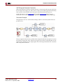
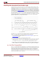
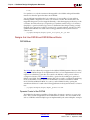
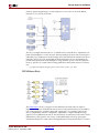
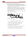
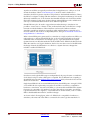
1
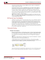
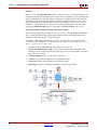
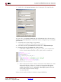
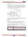
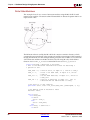
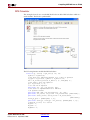
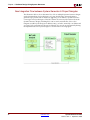
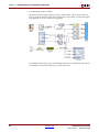
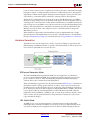
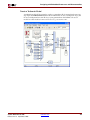
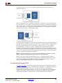
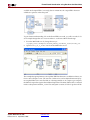
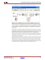
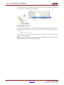
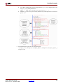
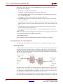
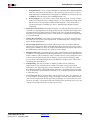
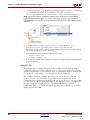
R
Shared Memory Support
FIFO block in user design. The read side of the FIFO is connected to PC interface logic that
allows the PC to read data from the FIFO during simulation.
In the figure below, the opposite wiring approach is used when a From FIFO block is
compiled for hardware co-simulation. In this case, the write side of the FIFO is connected
to PC interface logic, while the read side is connected to the user design logic. The host PC
writes data into the FIFO and the design logic may read data from the FIFO.
For designs that use hardware co-simulation, shared FIFO pairs are typically distributed
between software and FPGA hardware. In other words, one half of the pair is implemented
in the FPGA while the other half is simulated in software using a To or From FIFO block.
Together, the software and hardware portions form a fully functional asynchronous FIFO.
When a software / hardware shared FIFO pair is co-simulated, System Generator
transparently manages the necessary transactions between the PC and FPGA hardware.
When data is written to a software To FIFO block during simulation, the same data is
written to the FIFO in hardware. The design in hardware may then retrieve this data by
reading from the FIFO. Similarly, when data is written into the hardware FIFO by design
logic, the data may be read by the From FIFO software block. Note that the empty, full, read
and write count ports on the shared FIFO blocks pessimistically reflect the state of the
hardware FIFO counterpart. A software shared FIFO may connect to a hardware shared
FIFO simply by specifying the name of the shared FIFO as it was compiled for hardware
co-simulation.
System Generator for DSP
Release 10.1.3 September, 2008
www.xilinx.com
197