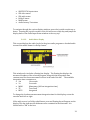
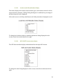
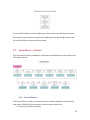
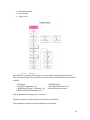
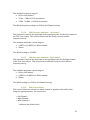
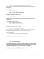
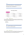
1
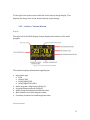
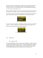
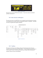
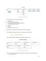
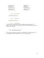
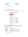
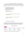
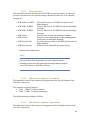
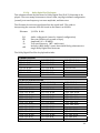
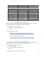
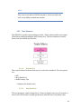
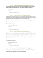
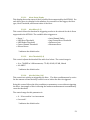
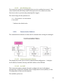
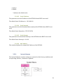
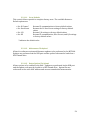
MT2000MultichannelBitstreamAnalyzer UserGuide MT2000version0.0.35andlater UserGuideversion0.95 TelosAlliance 1241SuperiorAvenue Cleveland,OH44114 (216)241‐7225 phone (216)241‐4103 fax L15/2/18083 1 WarrantyInformation DISCLAIMEROFWARRANTIES:ProductsmanufacturedbyLinearAcousticare warrantedagainstdefectsinmaterialandworkmanshipforaperiodoffive(5) yearsfromthedateofpurchase.TheinternalbatteryusedintheMT2000is warrantedforaperiodof90daysfromthedateofpurchase. THEREARENOOTHERIMPLIEDOREXPRESSWARRANTIESANDNOWARRANTY FORMERCHANTABILITYORFITNESSFORAPARTICULARPURPOSE. DuringthewarrantyperiodLinearAcousticInc.willrepair,oratourdiscretion replace,componentswhichprovetobedefective,providedtheunitisreturned, shippedpre‐paidtousdirectlywithareturnauthorization(RA)numberclearly markedonthepackaging.Pleasenote,thisRAnumbermustbepresentorpackage willberefusedandreturnedtosender. AllrequestsforrepairsMUSTincludetheunitserialnumbertoensurequickand accurateservice. DEFECTSCAUSEDBYUNAUTHORIZEDMODIFICATIONS,MISUSEORACCIDENTS, UNAUTHORIZEDCUSTOMERREPAIRS,ORANYFURTHERDAMAGECAUSEDBY INADEQUATEPACKAGINGFORSERVICERETURNARENOTCOVEREDBYTHIS WARRANTY. PLEASESAVETHESHIPPINGCARTONANDALLPACKINGMATERIALS.FAILURETO RETURNUNITINORIGINALSHIPPINGCARTONANDPACKINGMATERIALSWILL RESULTINACHARGEFORNEWSHIPPINGMATERIALS. LIMITATIONOFPERIODOFACTIONONCONTRACT:Noaction,regardlessofform, arisingoutofthetransactionsunderthisagreementmaybebroughtbybuyer,its successors,agentsand/orassigns,morethanthreeyearsfromdateofpurchase. LIMITATIONOFLIABILITY:ItisunderstoodandagreedthatLinearAcoustic’s liabilitywhetherincontract,intort,underanywarranty,innegligenceorotherwise shallnotexceedthecostofrepairorreplacementofthedefectivecomponentsand undernocircumstancesshallLinearAcousticbeliableforincidental,special,direct, indirectorconsequentialdamages,orlossofuse,revenueorprofitevenifLinear Acousticoritsagentshavebeenadvised,orallyorinwriting,ofthepossibilityof suchdamages. LinearAcoustic,the“LA”symbol,aretrademarksorregisteredtrademarksofLinearAcousticInc. ThisproductcontainstechnologiesfromDolbyLaboratories.Dolbyandthedouble‐Dsymbolare trademarksofDolbyLaboratories. Allothertrademarksremainthepropertyoftheirrespectiveowners. 2 Table of Contents Chapter1:Introduction..........................................................................................................................8 1.1. Introduction....................................................................................................................................8 1.2. WarrantyandFeedback.............................................................................................................8 Chapter 2: Overview and Connections............................................................................................9 2.1. Unpacking and Inspection...........................................................................................................9 2.2. Unit Overview..................................................................................................................................9 2.2.1. Front panel...............................................................................................................................9 2.2.2. Bottom....................................................................................................................................10 Connections...................................................................................................................................11 2.3. 2.3.1. Rear Panel.............................................................................................................................11 2.3.1.1. Power Connection.....................................................................................................11 2.3.1.2. AES Input.......................................................................................................................11 2.3.1.3. AES Output...................................................................................................................11 2.3.1.4. SDI Input........................................................................................................................12 2.3.1.5. SDI Output....................................................................................................................12 2.3.1.6. TOSLINK® Input...........................................................................................................12 2.3.1.7. TOSLINK Output..........................................................................................................12 2.3.1.8. VRef Input.....................................................................................................................12 2.3.1.9. HDMI Input...................................................................................................................12 2.3.2. Side Panel..............................................................................................................................13 2.3.2.1. Headphone Output...................................................................................................13 2.3.2.2. Ethernet Connection.................................................................................................13 2.3.2.3. USB Connector............................................................................................................13 Chapter 3: Detailed Operation.........................................................................................................14 3.1. Interface..........................................................................................................................................14 3.2. Joystick Encoder...........................................................................................................................14 3.2.1. Joystick Operations (Status / Control Window).........................................................14 3.2.2. Joystick Operations (Loudness / Volume Window).....................................................14 3.3. Display.............................................................................................................................................15 3.3.1. Display Window.......................................................................................................................15 3.3.2. Status / Control Window......................................................................................................15 3 3.3.3. Loudness / Volume Window...............................................................................................17 Display.................................................................................................................................................17 Volume Control................................................................................................................................17 3.4. Operation.......................................................................................................................................18 3.4.1. Power On / Off.........................................................................................................................18 3.4.2. Menu Structure and Navigation.........................................................................................19 3.4.3. Top Menu...................................................................................................................................19 3.4.3.1. Input Status Display..................................................................................................20 3.4.3.2. Audio Meter Display.................................................................................................21 3.4.3.3. Loudness and Dolby Metadata Display..............................................................22 3.4.3.4. AES / SMPTE stream status display.....................................................................22 3.4.3.5. Statistics Menu...........................................................................................................23 3.4.3.6. Setup Menu.................................................................................................................23 3.4.3.7. Version Number.........................................................................................................24 3.5. Setup Menu – In Detail..............................................................................................................25 3.5.1. Presets Submenu.....................................................................................................................25 3.5.1.1. Presets...........................................................................................................................26 3.5.1.2. Preset Name................................................................................................................30 3.5.1.3. Copy Preset..................................................................................................................31 3.5.2. I/O Submenu.............................................................................................................................31 3.5.2.1. Main Output Source.................................................................................................31 3.5.2.2. Downmix Type............................................................................................................32 3.5.2.3. SDI Embed Audio.......................................................................................................32 3.5.2.4. SDI Output 1/2 Source ‐ SDI Output 15/16 Source........................................32 3.5.2.5. SDI Validity Bit.............................................................................................................33 3.5.2.6. SDI Audio Bit................................................................................................................33 3.5.2.7. Idle Screen Dim...........................................................................................................33 3.5.3. MADI Output Submenu.........................................................................................................33 3.5.3.1. Enable MADI Output.................................................................................................34 3.5.3.2. MADI Output 1/2 Source ‐ MADI Output 15/16 Source...............................34 3.5.4. Loudness Meter Submenu...................................................................................................35 3.5.4.1. Loudness Mode..........................................................................................................35 3.5.4.2. 10 seconds Speech Gate..........................................................................................36 4 3.5.4.3. Main Loudness Meter Integration (Main Loud Type)...................................36 3.5.4.4. Secondary Loudness Meter Integration (Sec Loud Type)............................36 3.5.4.5. Floating Bar Graphical Loudness Meter (Graph Loud Type).......................37 3.5.4.6. Loudness Log Integration Time (Log Loud Type)............................................37 3.5.4.7. Loudness Logging Frequency (Log Frequency)................................................37 3.5.5. Signal Generator Submenu..................................................................................................37 3.5.5.1. Generated Stream.....................................................................................................38 3.5.5.2. PCM Generator Frequency – Left channel........................................................38 3.5.5.3. PCM Generator Frequency – Right channel.....................................................38 3.5.5.4. PCM Generator Amplitude – Left channel........................................................39 3.5.5.5. PCM Generator Amplitude – Right channel.....................................................39 3.5.5.6. PCM Channel Select..................................................................................................39 3.5.5.7. PCM Frequency Sweep – Minimum Frequency..............................................40 3.5.5.8. PCM Frequency Sweep – Maximum Frequency..............................................40 3.5.5.9. PCM Frequency Sweep Time.................................................................................40 3.5.6. File Playout Submenu............................................................................................................40 3.5.6.1. PCM File Stream.........................................................................................................41 3.5.6.2. DD File Stream............................................................................................................41 3.5.6.3. Dolby E File Stream...................................................................................................42 3.5.6.4. Dolby Digital Plus File Stream................................................................................44 3.5.6.5. File Playback Amplitude – Left channel..............................................................45 3.5.6.6. File Playback Amplitude – Right channel...........................................................45 3.5.7. Tests Submenu.........................................................................................................................46 3.5.7.1. Activate Test................................................................................................................46 3.5.7.2. Beep Flash Test...........................................................................................................46 3.5.7.3. Audio Latency Test....................................................................................................47 3.5.7.4. Audio Latency Status................................................................................................47 3.5.8. Video Generator Submenu..................................................................................................47 3.5.8.1. SDI Video Generator Enable...................................................................................48 3.5.8.2. SDI Video Standard....................................................................................................48 3.5.8.3. Ignore Dolby E Guard band Video (Ignore DE GB Vid)..................................48 3.5.8.4. Dolby E Guard Band Video Reference (DE GB Video Ref)............................49 3.5.8.5. Dolby E Line Position – NTSC (DE GB Line NTSC)............................................49 5 3.5.8.6. Dolby E Line Position – PAL (DE GB Line PAL)..................................................49 3.5.8.7. Dolby E Line Position – 720p (DE GB Line 720p).............................................49 3.5.8.8. Dolby E Line Position – 1080 (DE GB Line 1080).............................................50 3.5.9. Alerts Submenu........................................................................................................................50 3.5.9.1. Alerts Status Display.................................................................................................51 3.5.9.2. Alert When (1‐4)........................................................................................................51 3.5.9.3. Alert Threshold (1‐4).................................................................................................51 3.5.9.4. Alert On Delay (1‐4)..................................................................................................51 3.5.9.5. Alert Off Delay (1‐4)..................................................................................................52 3.5.10. Communication Submenu...............................................................................................52 3.5.10.1. Communication Status Display.........................................................................52 3.5.10.2. Use DHCP.................................................................................................................52 3.5.10.3. Static IP Address....................................................................................................53 3.5.10.4. Static Netmask.......................................................................................................53 3.5.10.5. Static Gateway........................................................................................................53 3.5.10.6. MAC Address...........................................................................................................53 3.5.11. System Submenu................................................................................................................53 3.5.11.1. Set to Defaults........................................................................................................54 3.5.11.2. Maintenance File Upload....................................................................................54 3.5.11.3. Device Options File Upload................................................................................54 Problems and Possible Causes..............................................................................................................55 4.1 Unit won’t power on..............................................................................................................55 4.2 Volume Control does not work..........................................................................................55 4.3 Unit does not recognize the input signal........................................................................55 4.4 Cannot change test generator or file playback settings............................................55 4.5 SDI output stream does not contain signals generated by the MT2000..............55 Chapter5:Specifications....................................................................................................................56 5.1. Physical..........................................................................................................................................56 5.2. Electrical........................................................................................................................................56 5.3. Audio...............................................................................................................................................57 5.4. Other................................................................................................................................................58 6 Table of Figures Figure1MT2000FrontPanel.........................................................................................................10 Figure2MT2000RearPanel...........................................................................................................11 Figure3MT2000SideView.............................................................................................................13 Figure4MainDisplayScreen..........................................................................................................15 Figure5Status/ControlWindow...................................................................................................16 Figure6Loudness/VolumeWindow...........................................................................................17 Figure7VolumeControlDisplay...................................................................................................18 Figure8SpeakerMute/UnmuteDisplay....................................................................................18 Figure9HomeScreen.........................................................................................................................19 Figure10MenuTree...........................................................................................................................19 Figure11TopLevelMenu................................................................................................................20 Figure12InputStatusDisplay........................................................................................................20 Figure13AudioMeterDisplay.......................................................................................................21 7 Chapter 1: Introduction 1.1. Introduction CongratulationsonyourpurchaseoftheLinearAcousticMT2000bitstream analyzer! TheMT2000iscapableofanalyzing,monitoring,andmeasuringtheloudnessof audiosignalscarriedinmanycommonlyusedbroadcastinterfacessuchasAES‐3, SDI(bothHD‐andSD‐),TOSLINK®optical,andoptionallyDVB‐ASItransport streams,MADI,andHDMI.PCM,Dolby®E,DolbyDigital(alsocalledAC‐3),and DolbyDigitalPlus(alsocalledE‐AC‐3)aresupported.TheMT2000iscapableof measuringtheloudnessofaudioinputsignalsfollowingtheITUBS.1770standard andusingDolbyDialogueIntelligencewhereapplicable. TheMT2000isalsocapableofgeneratingaudiotestsignals,playingbackpre‐ encodedDolbybitstreams,performingcertainaudiotestssuchasaudiolatency,and generatingA/VsyncFlash‐Beepsignals.Abuiltinvideosignalgeneratoris availableforgeneratingSDIoutputteststreams. UtilityfunctionssuchasSDIde‐embedding,embedding,pairshuffling,Dolby decodinganddownmixingarealsosupportedbytheMT2000. Youwillquicklyseethatthisunitisasusefultoanyaudioengineerasadigital multimeteristoanelectrician! 1.2. Warranty and Feedback Pleasetakeamomenttofilloutthepostage‐paidwarrantycardincludedwiththe unitanddropitinthemail.Thiswillenableustocontactyouifthereareany softwareordocumentationissues. Additionally,ifthisisyourfirstLinearAcousticproductoryouhavenotalready registeredforauseraccountonourwebsite,pleasedoso.Softwareupdatesand thelatestdocumentationarealwaysavailablethere,atyourconvenience,24/7/365. Pleasevisitwww.linearacoustic.comandclickonthe“register”buttonatthetop Also,weareveryinterestedinyourfeedback.Thisunitwasdesignedbasedoninput gatheredfrommanybroadcastengineersanditwillevolvefurtherthanksto ongoingsuggestionsandcommentsfromusers. Welookforwardtohearingfromyou! 8 Chapter 2: Overview and Connections 2.1. Unpacking and Inspection Beforeunpackingtheunit,inspecttheoutercartonforshippingdamage.Ifthe cartonshowsdamage,inspecttheunitinthoseareas.Pleasesavethecarefully designedshippingcartonandpackingmaterials.Intheunlikelyeventthattheunit needstobereturnedtothefactory,alternatecartonsorpackingmaterialsmaynot beadequateandcancausedamagenotcoveredbywarranty. Thefollowingessentialitemsareprovidedwiththeunit: Shipping/Carryingcase PowersupplywithanIECpowercord(stylematchescountryoforder) Quick‐startsheettogetyouupandrunning USBmemorystickcontainingdocumentationincludingthismanual USBtoRS‐485adapter microBNCtostandardBNCadapter ahandyblackpen. Warrantyinformation:PleasefilloutandreturnthewarrantycardtoLinear Acoustictoensureyoursoftwareanddocumentationarekeptuptodate. 2.2. Unit Overview ThissectionintroducesyoutoMT2000anditsviews: 2.2.1. Front panel OnthefrontpaneloftheMT2000,youwillfindfromthetopdown: OLEDdisplay backlitLinearAcousticlogoandpowerindicator joystick/encoder internalspeaker TheOLEDdisplayprovidestheuserwithvisualfeedbackandinteractionastowhat theMT2000isdoing,parametersettings,andinputsignalstatus. TheLEDbacklitLinearAcousticlogoactsasapowerindicator.TheLEDsglowred astheunitinitializes,andthenturntoblueastheunitoperatesnormally. MT2000includesajoystick/encoderonthefrontpanel.Alladjustmentsand parametersettingsaremadewiththiscontrol.Itiscapableofbeingpressedup 9 (towardstheconnectors),down(towardsthespeaker),left,right,andin.Itisalso capableofbeingrotatedleftandright.Thefunctionthatiscontrolledbyjoystick pressesandencoderturnsmayvarydependingonthemenuormodetheMT2000is in. Figure1MT2000FrontPanel AninternalspeakerisincludedintheMT2000.Thisallowstheusertolistentothe signalbeingmonitored. 2.2.2. Bottom Aretractablekickstandisdesignedintothebottomoftheunit. Toextendthekickstand,gentlypullupontheendofthekickstandthatconnectsto thehinge,andlifttheotherendup. Toretractthekickstand,simplypushtheendbacktowardsthechassis. 10 2.3. Connections Thischaptercov versallconn nections 2.3.1. Re ear Panel Therrearpanelo oftheMT2000containssthemajoriityoftheco onnectionsw whichwillb be used. Figure2M MT2000Rear Panel n 2.3.1.1. Powerr Connection utwithweaatherproofp plugisproviided.Thisacceptsa1 12VDC ADCpowerinpu heinternalb battery.Theecenterposst inputt,andisuseedtopowertheunitandchargeth istheepositiveteerminaland dthesleeveisground.T Thesleeveiisthreadedandthe providedpowerrsupplyinclludesalock kingringtoeensurethattthepowerconnection n doesnotacciden ntallybecom meundone. 2.3.1.2. AES Input AES‐3idorMAD DIsignalsareeacceptedv viathe75‐oohmBNCco onnector.Co onsumer form mattedsignalls(IEC6095 58orS/PDIIF)signalsaarealsoacceeptedatthissinput. 2.3.1.3. AES Ou utput AudiosignalsformattedtottheAES‐3id dstandardoorMADIsignalsareouttputviathe AESo output. 1 11 2.3.1.4. SDI Input AnautosensingSD/HD‐SDIinputisincludedontheMT2000.Itallowsaccesstoall 16audiochannelsintheSDIstreamforanalysis,monitoring,decoding,de‐ embedding,andpairshuffling.TheSDIinputisalsousedforDVB‐ASIinput streams,whentheDVB‐ASIoptionisenabled. 2.3.1.5. SDI Output AnSD/HD‐SDIoutputisincludedontheMT2000.All16audiochannelsintheSDI streamareavailableforembeddingandchannelshuffling.TheSDIoutputisalso usedforoutputtingDVB‐ASIstreams,whentheDVB‐ASIoptionisenabled. 2.3.1.6. TOSLINK® Input Consumerformattedsignals(IEC60958orS/PDIF)signalsareacceptedatthis opticalinput.PCMandDolby®Digitalstreamsareacceptedatthisinput. Note! ADATstreamsarenotsupportedviatheTOSLINKconnections. 2.3.1.7. TOSLINK Output PCMandDolbyDigitalconsumerformattedsignals(IEC60958orS/PDIF)signals arecapableofbeingoutputfromthisopticaloutput. 2.3.1.8. VRef Input AnalogVerticalReference(VRef)isacceptedviathemicroBNCconnector.This inputallowsforguardbandmeasurementofDolbyEstreams. 2.3.1.9. HDMI Input AnoptionalHDMIinputisavailabletoaidinthetestingofcompletebroadcast systems,allowingconnectiontoconsumerdevicessuchasSetTopBoxesanddigital televisions. Note! OnlyPCM,DolbyDigital(AC‐3)andDolbyDigitalPlus(E‐AC‐3) streamsaresupportedviatheHDMIconnection. 12 2.3.2. Side Panel TherightsidepaneloftheUPMAXv4includesseveralconnections. Figure3MT2000SideView 2.3.2.1. Headphone Output Astereo1/8”(~3.5mm)stereoheadphonejackisincluded.Thistip/ring/sleeve connectoracceptsmostheadphones,andiswiredtip=left,ring=right,sleeve= shield.Whenheadphonesarepluggedintothisconnector,theinternalspeakeris muted. 2.3.2.2. Ethernet Connection AstandardEthernetconnectorisincluded.Thefunctionofthisconnectoris reservedforfutureuse. 2.3.2.3. USB Connector AUSBinputisincluded.Thisisusedforsoftwareupgrades. 13 Chapter 3: Detailed Operation 3.1. Interface TheMT2000includesaJoystick/EncoderandanOLEDdisplayonthefrontpanel. Alluseradjustmentsaremade,andallvalues,statuses,andparametersare displayedfromthefrontpanel.Thisdisplayprovidestheprimaryuserinterface. 3.2. Joystick Encoder TheMT2000includesajoystick/encoderonthefrontpanel.Alladjustmentsand parametersettingsaremadewiththiscontrol.Itiscapableofbeingpressedup (towardstheconnectorpanel),down(towardsthespeaker),left,right,andin.Itis alsocapableofbeingrotatedleftandright.Thefunctionthatiscontrolledby joystickpressesandencoderturnsmayvarydependingonthemenuormodethe MT2000isin. 3.2.1. Joystick Operations (Status / Control Window) Pressingthejoysticktotheleftactsasanescapekeyandbacksyououttowards themainmenu. Pressingthejoysticktotherightnavigatesthroughthemenuorsubmenu categories.ItalsoactsasanEntercontrolwhenadjustingparameters Pressingthejoystickupordownnavigatesthroughaparticularmenuor submenucategory. Turningthejoystickallowsadjustmentofparametersandcontrolsettings. Pressingthejoystickinandholdingitactsasthepoweron/offswitch Pressingthejoystickintwicequickly(“double‐click”)changestheactive display/controlwindow. 3.2.2. Joystick Operations (Loudness / Volume Window) Pressingthejoysticktothelefthasnofunction. Pressingthejoysticktotherighthasnofunction. Pressingthejoystickupresetstheloudnessmeasurement Pressingthejoystickdownmutesorunmutesthespeakerandheadphones. Turningthejoystickadjuststhelisteningvolume. Pressingthejoystickinandholdingitactsasthepoweron/offswitch 14 Pressingthejoystickintwicequickly(“double‐click”)changestheactive display/controlwindow. 3.3. Display 3.3.1. Display Window TheMT2000includesanOLEDdisplayonthefrontpanel.Thisdisplayprovidesthe primaryuserinterface Figure4MainDisplayScreen Thedisplayisdividedintotwowindows: TheStatus/ControlWindowoccupiesthelefthalfofthedisplay. TheLoudness/VolumeControlWindowoccupiestheright. Onlyoneofthesewindowsmaybecontrolledatatime.Theactivewindowis highlightedwithayellowbaratthetop.Intheimageshownabove,theStatusand ControlWindowistheactivewindow. Tochangewhichwindowisactive,pressthejoystickencoderinrapidlytwotimes (double‐click). 3.3.2. Status / Control Window 15 Figure5Sta atus/ControlW Window TheS Status/Con ntrolWindo owdisplaycchangesdep pendingonw whichmenu u,submenu, ordisplayiscurrentlychosen.Atthettopofthisw window,theereissomeinformation n whichmenu uisinuse. thatiisalwaysdiisplayedreggardlessofw nameoftheeactivepressetisalwayssdisplayedinthetopleftcorner. Then Toth herightofth heActivePrresetdisplay yisaniconwhichdisp playsthestaatusofthe speak kerandheaadphoneouttput. Aniconw whichlookslikeaspeak kerisdisplaayedwhentthespeakerr/headphon ne outputsaareactive. whentheespeaker/h headphoneo outputsare muted,thefollowingicconis displayed d: herightofth hespeakersstatusisaniconwhich hindicatesw whethertheMT2000is Toth being goperatedffromACPow wer(MainsLine)orfroomtheinterrnalbatteryy. Aniconw whichlookslikeabatteeryisdisplayyedwhenth heunitisbeeing poweredfromitsintternalbatteery. whentheeunitisbein ngrunfrom mtheACLin ePower(M Mainsinput),the following giconisdisp played: 1 16 Totherightofthepowersourceindicatoristhebatterychargedisplay.This displaysthechargeleveloftheinternalbatteryinpercentage. 3.3.3. Loudness / Volume Window Display TherighthalfoftheOLEDdisplayalwaysdisplaystheloudnessoftheaudio program, Figure6Loudness/VolumeWindow Thiswindowdisplaysinformationregardingthe: Inputaudiotype PCM DolbyE(DE) DolbyDigital(DD) DolbyDigitalPlus(DD+) Audioprogramconfiguration(DolbyE) Programbeingmonitored(DolbyE) Dolbydialognormalization(dialnorm)value Mainloudnesslevelandintegrationtime Secondaryloudnesslevelandintegrationtime Volume Control 17 Sincethevolumecontroldeterminestheloudnesslevelofthesignalbeingapplied directlytoyourears,it’sonlylogicalthatintheloudnesswindowiswhereyou wouldbeallowedtocontrolthisfunction,right?Ourdevelopmentteamthought so,sothisiswherewedecidedtoputit. WhentheLoudnessWindowisactive,thejoystickencoderadjuststhevolumeofthe internalspeakerorheadphoneoutputs,aswellasmute/unmuteofthoseoutputs. Toadjustthevolumeofthespeakerorheadphones,turnthejoystickencoderleftor right.Apop‐upwindowappearsanddisplaysthelevelofthevolumecontrol: Figure7VolumeControlDisplay Tomuteorunmutethespeaker/headphones,presstheencoderdown(towardsthe speaker).TheiconintheStatus/ControlMenuwillchangeaccordingly,anda MuteorUnmutemessagewilltemporarilybedisplayed. Figure8SpeakerMute/UnmuteDisplay 3.4. Operation 3.4.1. Power On / Off TopowertheMT2000on,presstheencoderknobinandholdit.Withinacoupleof secondstheLEDsbehindtheLinearAcousticlogowillbrieflylightupred,andthen changetoblueastheunitcontinuestoboot.Ittakesseveralsecondsfortheunit torunthroughitsbootuproutine,self‐diagnostics,andbereadytoacceptaudio. OncetheOLEDdisplayshowsthehomescreen,theunitisreadyforuse. 18 Figure9HomeScreen TheprocesstoturntheMT2000offissimilar.Presstheencoderinandholdit untiltheunitshutsoff. 3.4.2. Menu Structure and Navigation ThemenustructurefortheMT2000isverystraightforwardandsimpletonavigate eventhoughtherearemanyoptionsandparametersabletobeadjusted.Themenu structureisorganizedintologicalsubmenus Figure10MenuTree 3.4.3. Top Menu Thetopmenuallowsforthedisplayofimportantinformationabouttheinput streaminaveryquickandeasytofindmanner.Fromwithinthetoplevelmenu,it isalsopossibletogettostatisticsandsetupmenus,alongwithdeterminingthe softwarereleaseversionoftheMT2000. 19 Figure11TopLevelMenu Thetopmenulevelincludesselectionsfor: Inputstatus AudioMeters(homescreen) LoudnessandDolbymetadataparameters AES/SMPTEheaderstatus Statistics Setup Softwarereleaseversion Manyofthemenuoptionsincludesub‐menusorsub‐displays. Thesedisplaysandmenusaredescribedinthefollowingsections. 3.4.3.1. Input Status Display Thiswindowdisplaysinformationregardingtheinputsignal. Figure12InputStatusDisplay Thereareseveralsub‐windowsinthisdisplaywhichincludeinformationabout: Audioinputstatus 20 SMPTE337Minputstatus SDIvideostatus SDIaudiostatus DolbyEstatus MADIstatus AudioLatencyTeststatus Tonavigatethroughthevariousdisplaywindows,pressthejoystickencoderupor down.Pressingthejoystickencodertotheleftactsasanescapekeyandjumpsthe displaybacktotheAudioInputStatuswindowattheverytop. 3.4.3.2. Audio Meter Display Thisscreendisplaystheaudiolevelsforthegivenaudioprogramordecodedaudio streamiftheaudioformatisaDolbyformat. Figure13AudioMeterDisplay Thiswindowalsoincludesafloatingbardisplay.Thefloatingbardisplaysthe measuredloudnessoftheselectedprogram,alongwiththeintegrationtime constantusedforthemeasurementinaboxattheendofthebar.Theavailable integrationtimeconstantsare: 10s 10seconds 3s 3seconds MOM Momentary(400msintegrationtime) TP True‐Peak INTG Integrated Tochangetheloudnessmeasurementintegrationtimeforthisdisplay,rotatethe encoderknobleftorright. IftheaudiosourceisaDolbycodedformat,asecondfloatingbarwillappearonthe display.Thisbarindicatesthedialnormvaluecontainedinthebitstream.Itis labeledwitha“DN”inthebox. 21 3.4.3.3. Loudness and Dolby Metadata Display Thismenudisplaystheloudnessmeasurementtype,andloudnessvaluesforallthe supportedtimeconstants.IfDolbyDialogIntelligenceisenabled,thepercentageof measuredspeechisalsodisplayed. IftheaudiosourceisaDolbycodedformat,theDolbymetadataisdisplayedaswell. Tochangetheloudnessvaluesormetadataparametersbeingdisplayedonthe screen,rotatetheencoderknobleftorright. 3.4.3.4. AES / SMPTE stream status display TheAESStatuswindowdisplaysinformationabouttheinputAESstream. Tochangethevaluebeingdisplayedonthescreen,rotatetheencoderknobleftor right. 22 3.4.3.5. Statistics Menu ThisMenudisplaysstatisticsandinformationabouttheMT2000.Information regarding: ProductOptions Alertsettingsandvalues DolbyCAT1100card HowlongtheMT2000hasbeenrunning,andthetimeofthelastreference change areallavailableinthismenu Tonavigatethroughthevariousdisplaywindows,pressthejoystickencoderupor down.Pressingthejoystickencodertotheleftactsasanescapekeyandjumpsthe displaybacktothemainStatisticsMenuoptionatthetopmenulevel. 3.4.3.6. Setup Menu TheSetupMenuiswhereallconfigurationsettingsfortheMT2000aremade 23 Thesetupmenucontainsmultiplesubmenus,withparametersandsettings organizedintologicalsubgroups.Therearesubmenusfor: Presets I/O MADIOut LoudnessMeter SignalGenerator FilePlayout Tests VideoGenerator Alerts IPCommunication SystemSettings TheSetupMenu,itssubmenus,andtheparameters/controlscontainedwithinare describedindetailthesection6below. 3.4.3.7. Version Number TheMT2000softwareversionnumber,firmware(FPGA)version,installpackage, andbootloaderversionanddatestampareavailablefromthetopmenu. 24 ToviewtheFirmwareversionnumberpressthejoystickencoderdownonetime. Pressingthejoystickdownasecondtimedisplaystheinstallpackageversionand thecorebootloaderversionanddatestamp. 3.5. Setup Menu – In Detail TheSetupmenuoptions,submenus,andparameterdefinitionsaredescribedinthe followingsections: 3.5.1. Presets Submenu ThePresetsMenuiswhereuserpresetscanberecalled,modified,stored,named, andcopied.WithinthePresetsmenu,therearemenuoptionsfor: Preset(16possiblelocations) 25 PresetParameters PresetName CopyPreset 3.5.1.1. Presets TheMT2000iscapableofstoringupto16userdefinedandadjustablepresets. Theunitshipsfromthefactorywithseveralpresetspre‐loadedintotheunit,which include: •AESInput •TOSLINKinput •SDIInput(Channels1‐8) •SDIInput(Channels9‐16) •MADIInput(Group1,Channels1‐8) •InternalReferenceclock •HDMIInput(PCMChannels1/2) Plusanadditional9emptypresetlocations Thefactorypresetsloadedintotheunitmaybeoverwritten. Theparameterswhicharestoredwithinapresetinclude: 26 3.5.1.1.1. Processor Input Source Thisselectstheinputsourceusedtomonitorandmeasureloudnessof.The availableoptionsforthisare: •AESIn* •MADI(multich) •TOSLINKIn •SDI(multich) •HDMIIn •DVB‐ASIIn *indicatesthedefaultvalue 3.5.1.1.2. SDI Processor Input TheMT2000iscapableofmeasuringmultichannelPCMsources(upto8‐channels) frominterfaceswhicharecapableofsupportingit.Thereare4parameterstoselect theaudiopairfromtheSDIstreamastheinput.Theseare“SDIProcIn1/2”,“SDI ProcIn3/4”,“SDIProcIn5/6”,and“SDIProcIn7/8”. Theavailableoptionsfortheseparametersare: •SDIIn1/2 •SDIIn11/12 •SDIIn3/4 •SDIIn13/14 •SDIIn5/6 •SDIIn15/16 •SDIIn7/8 •Mute •SDIIn9/10 *thedefaultvalueisa1to1matchingofSDIchannelpairstoSDIProcessing Input.Example:SDIIn1/2istheinputpairforSDIProcIn1/2 WhenmeasuringmultichannelPCM,standardSMPTEroutingisusedbythe MT2000.Thismeansthat: SDIProcIn1/2=Left/Right SDIProcIn3/4=Center/LFE SDIProcIn5/6=LeftSurround/RightSurround SDIProcIn7/8=LeftRearSurround/RightRearSurround Whenmeasuringcodedaudio,inputthecodedaudioonSDIProcIn1/2andmute theother3SDIProcessorInputs(3–8). 3.5.1.1.3. MADI Input Group ThismenuselectstheMADIGrouptohaveapairselectedfromformonitoringand measuring.Theoptionsare: •Group1* •Group5 27 •Group2 •Group6 •Group3 •Group7 •Group4 •Group8 *indicatesthedefaultvalue **requirestheMADIoptiontobeenabled Note! MADIstreamsshouldbeinputandoutputviatheAESconnections. 3.5.1.1.4. MADI Input Channel Pair TheMT2000iscapableofmeasuringmultichannelPCMsources(upto8‐channels) frominterfaceswhicharecapableofsupportingit.Thereare4parameterstoselect theaudiopairfromtheMADIstreamastheinput.Theseare“MADIProcIn1/2”, “MADIProcIn3/4”,“MADIProcIn5/6”,and“MADIProcIn7/8”. Theavailableoptionsfortheseparametersare: •Ch1/2 •Ch11/12 •Ch3/4 •Ch13/14 •Ch5/6 •Ch15/16 •Ch7/8 •Mute •Ch9/10 *thedefaultvalueisa1to1matchingofinputchannelpairstoMADI ProcessingInputwithintheselectedMADIGroup.Example:SDIIn1/2is theinputpairforMADIProcIn1/2 WhenmeasuringmultichannelPCM,standardSMPTEroutingisusedbythe MT2000.Thismeansthat: MADIProcIn1/2=Left/Right MADIProcIn3/4=Center/LFE MADIProcIn5/6=LeftSurround/RightSurround MADIProcIn7/8=LeftRearSurround/RightRearSurround Whenmeasuringcodedaudio,inputthecodedaudioonMADIProcIn1/2andmute theother3MADIProcessorInputs(3–8). 28 3.5.1.1.5. HDMI Input Channel Pair ** WhentheHDMIoptionisenabled,thismenuallowstheselectionofthechannelpair fromtheHDMIconnectiontobemonitored.Theoptionsare: •PCMCh1/2* •SPDIFCh1/2 •PCMCh3/4 •SPDIFCh3/4 •PCMCh5/6 •SPDIFCh5/6 •PCMCh7/8 •SPDIFCh7/8 *indicatesthedefaultvalue **requirestheHDMIoptiontobeenabled 3.5.1.1.6. Clock Source ThecontrolallowsselectionofthereferenceclocksourceusedbytheMT2000.The availableoptionsare: •AESInput* •TOSLINK •HDMI •MADI •SDI •VRef •Internal48KHz *indicatesthedefaultvalue 3.5.1.1.7. DVB‐ASI PID ** ThiscontrolallowsselectionoftheaudioPIDintheDVB‐ASIstreamtomonitor. Thedefaultvalueis: •0x0010 **requirestheDVB‐ASIoptiontobeenabled Note! DVB‐ASIstreamsshouldbeinputandoutputviatheSDI connections. 3.5.1.1.8. SRC Bypass TheMT2000includessamplerateconverters(SRC)ontheAESandTOSLINKinputs. TheseSRCsaccommodateinputaudioifitisatadifferentsamplerate(44.1kHz)or 29 moretypicallyifitisusingadifferentclockreferencethantheoutputaudio.The outputsoftheSRCsgotothemainoutput,theSDIembedder,andtheMADIinserter. Thiscontrolallowstheasynchronoussamplerateconvertersusedontheinputto theMT2000tobebypassed.Theoptionsare: •Enable (SRCsbypassed) •Disable* (SRCsincircuit) *indicatesthedefaultvalue Unlesstheinputandoutputaudioareknowntosynchronous,orDolbycodedaudio isnotbeingdecodedcorrectly(soundsliketeethchattering),SRCBypassshouldbe setto“OFF” 3.5.1.1.9. Apply DD/+ DRC ThiscontrolallowsfortheselectionofdynamicrangecompressionduringtheDolby DigitalorDolbyDigitalPlusdecode.Theavailableoptionsforthisare: •Dialnorm* Dialnormonly •LineMode+Dn DialnormwithLineModeCompression •RFMode+Dn DialnormwithRFModeCompression *indicatesthedefaultvalue 3.5.1.1.10. Apply DE DRC ThiscontrolallowsfortheselectionofdynamicrangecompressionduringtheDolby DigitalorDolbyDigitalPlusdecode.Theavailableoptionsforthisare: •Bypass* NoDynamicRangeCompressionordialnormapplied •Dialnorm Dialnormscalingapplied •LineMode+Dn DialnormwithLineModeCompression •RFMode+Dn DialnormwithRFModeCompression *indicatesthedefaultvalue 3.5.1.2. Preset Name EachPresetincludesa15‐characterpresetname.Presetsareabletobenamedor renamedtosomethingmeaningfulandintuitive. Tonameapreset: Presstheencodertotheleftortotherighttoselectthespacetoupdate.Rotatethe encoderleftorrighttoselectthedesiredcharacter.Oncethepresetnamehasbeen 30 changedtothedesiredname,keeppressingtheencodertotherightthroughallthe spacestoacceptthechangeinthename. 3.5.1.3. Copy Preset TheMT2000allowsuserstocopypresetinformationfromanotherpresetintothe currentworkingpreset. Tocopyapreset:Enterthe“CopyPreset”menuandpressthejoystick/encoder down.Thedisplaywillshow“CopyFromPreset”andthecurrentpresetname. Rotatethejoystick/encoderuntilthedesiredpresettobecopiedisfound,then pressthejoysticktotherighttoacceptit. 3.5.2. I/O Submenu TheI/Osubmenuiswhereaudioinputandoutputoptionsthatarenotstoredin presetsorarerelatedtoMADIOutputsarecontrolled. 3.5.2.1. Main Output Source ThemainoutputsourceistheaudiobeingoutputattheAESandTOSLINKoutputs. ThissignalcanalsobeoptionallyembeddedintoSDIandMADIoutputs.The choicesforthemainoutputsourceare: •Downmix* •SDIInput7/8 •SignalGenerator •SDIInput9/10 31 •FilePlayout •MADIInput •SDIInput1/2 •SDIInput3/4 •SDIInput5/6 •SDIInput11/12 •SDIInput13/14 •SDIInput15/16 •AESIn •TOSLINKIn *indicatesthedefaultvalue Thedownmixoptionisadownmixofthemainprogrambeingdecodedand monitored.Iftheaudioprogramcontainsmorethan2‐channels,itwillbe downmixedtostereoforyourlisteningpleasure. 3.5.2.2. Downmix Type ThedownmixtypebeingperformedbytheMT2000fortheMainOutputis selectableandisstoredaspartofapreset.Theavailablechoicesare: •LtRt* LeftTotal/RightTotal.ADolbySurroundencodedformat •LoRo LeftOnly/RightOnly.Nophaseshiftinformationinthe surroundchannels.Recommendedforheadphonemonitoring andmonodownmixes •Auto Baseduponpreferreddownmixmetadatavaluescontainedina Dolbybitstream *indicatesthedefaultvalue 3.5.2.3. SDI Embed Audio ThiscontroldetermineswhetheraudioisbeingembeddedintotheSDIoutputor simplypassedthroughfromtheSDIinput.Thechoicesare: •Enable •Disable* *indicatesthedefaultvalue 3.5.2.4. SDI Output 1/2 Source ‐ SDI Output 15/16 Source Thefollowing8parametersettingsselecttheaudiosourcetobeembeddedintothe variousaudiopairsinanHD/SD‐SDIstream.Thedefaultvalueisthatthesame inputpairismatchedtothesameoutputpair.Example:SDI1/2inputisroutedto SDI1/2output.Theavailableoutputsourceoptionsare: •SDIInput1/2 •SDIInput15/16 •SDIInput3/4 •Muted 32 •SDIInput5/6 •SDIInput7/8 •SDIInput9/10 •SDIInput11/12 •SDIInput13/14 3.5.2.5. SDI Validity Bit Reservedforfutureuse. 3.5.2.6. •MainOutput •AESInput •TOSLINKInput •SignalGenerator •FilePlayout SDI Audio Bit Reservedforfutureuse. 3.5.2.7. Idle Screen Dim TheOLEDscreenautomaticallydimsaftersittingidleforapproximately2.5 minutes.Dimvaluesvaryfrom6%(nearlyoff)to100%(fullbrightness),withthe defaultvaluebeing87%. 3.5.3. MADI Output Submenu ThissubmenudeterminesthebehavioroftheMADIoutput.MADIchannels1‐16 areduplicatedforMADIoutputchannels17‐32,33‐48,and49‐64. 33 3.5.3.1. Enable MADI Output Thefollowing8parametersettingsselecttheaudiosourcetobeembeddedintothe variousaudiopairsinanHD/SD‐SDIstream.Thedefaultvalueisthesameinput pairmatchedtotheoutputpair.Theavailableoutputsourceoptionsare: •Enable •Disable* *indicatesthedefaultvalue 3.5.3.2. MADI Output 1/2 Source ‐ MADI Output 15/16 Source Thefollowingparametersettingsselecttheaudiosourcetobeembeddedintothe first8audiopairs(16‐channels)inaMADIstream.Thedefaultvalueisthesame inputpair(1‐4)matchedtotheoutputpair(1‐4and5‐8).Theavailableoutput sourceoptionsare: •MADIInput1/2 •MainOutput •MADIInput3/4 •AESInput 34 •MADIInput5/6 •MADIInput7/8 •Muted *indicatesthedefaultvalue •TOSLINKInput •SignalGenerator •FilePlayout 3.5.4. Loudness Meter Submenu ThissubmenuallowstheconfigurationoftheloudnessmetersusedintheMT2000 3.5.4.1. Loudness Mode Thismenuallowstheloudnessmeasurementmodetobeselected.Loudness estimationisperformedbasedontheITUBS.1770standard.Theavailable loudnessmodeoptionsare: •BS1770‐1 ITUBS.1770‐1 •BS1770‐1+D ITUBS.1770‐1+DolbyDialogIntelligence •Leq(A) LeqAscale •Leq(A)+D LeqAscale+DolbyDialogIntelligence •BS1770‐2 ITUBS.1770‐2 •BS1770‐2+D* ITUBS.1770‐2+DolbyDialogIntelligence* *indicatesthedefaultvalue 35 3.5.4.2. 10 seconds Speech Gate Thismenuallowsthespeechgatingforthe10secondloudnessmeasurement windowtoeitherruncontinuouslyortostopandholdwhenspeechisnotdetected. Theavailableloudnessmodeoptionsare: •Continuous* •HoldNon‐Speech *indicatesthedefaultvalue 3.5.4.3. Main Loudness Meter Integration (Main Loud Type) Thismenuallowstheloudnessmeasurementmodeforthemainloudnessmeterto beselected.DifferentintegrationtimesandTrue‐Peakmeasurementareselectable. Theavailableloudnessmodeoptionsare: •IntegratedLoudnessmeasurement* •10SecondLoudnessmeasurement •3SecondLoudnessmeasurement •MomentaryLoudnessmeasurement •MaximumTrue‐Peak *indicatesthedefaultvalue 3.5.4.4. Secondary Loudness Meter Integration (Sec Loud Type) Thismenuallowstheloudnessmeasurementmodeforthesecondaryloudness metertobeselected.DifferentintegrationtimesandTrue‐Peakmeasurementare selectable.Theavailableloudnessmodeoptionsare: •IntegratedLoudnessmeasurement* •10SecondLoudnessmeasurement •3SecondLoudnessmeasurement •MomentaryLoudnessmeasurement •MaximumTrue‐Peak *indicatesthedefaultvalue 36 3.5.4.5. Floating Bar Graphical Loudness Meter (Graph Loud Type) Thismenuallowstheloudnessmeasurementmodeforthefloatingbarloudness meter,shownontheaudiometerdisplay,tobeselected.Differentintegrationtimes andTrue‐Peakmeasurementareselectable.Theavailableloudnessmodeoptions are: •IntegratedLoudnessmeasurement* •10SecondLoudnessmeasurement •3SecondLoudnessmeasurement •MomentaryLoudnessmeasurement •MaximumTrue‐Peak *indicatesthedefaultvalue 3.5.4.6. Loudness Log Integration Time (Log Loud Type) Reservedforfutureuse. 3.5.4.7. Loudness Logging Frequency (Log Frequency) Reservedforfutureuse. 3.5.5. Signal Generator Submenu TheMT2000includesa2‐channelPCMsignalgeneratortoaidintroubleshooting andcalibratingsystems.Thetwochannelsarecapableofbeingoperatedand configuredindividuallyforbothfrequencyandamplitude,orlinkedtogether. TheparametersandcontrolsintheSignalGeneratorsubmenuare: 37 3.5.5.1. Generated Stream ThisparametercontrolsthefunctionofthePCMtesttonesgenerator.Itallowsfor presetstobeselectedorforcustomsettingscontrolledbytheuser.Theavailable settingsare: •PCM400Hz‐20dBFS* Preset400Hztoneat‐20dBFSinbothLeftand Rightchannels •PCM1KHz‐20dBFS Preset1KHztoneat‐20dBFSinbothLeftandRight channels •PCM5KHz‐20dBFS Preset5KHztoneat‐20dBFSinbothLeftandRight channels •PCMSilence PresetSilenceinbothLeftandRightchannels •PCMCustom Allowsforuseradjustablefrequencyandamplitude inboththeLeftandRightchannels •PCMFSwp20‐12K Presetfrequencysweepat‐20dBFSinbothLeftand Rightchannels •PCMFSwpCustom Allowsforuseradjustablefrequencysweep *indicatesthedefaultvalue Note! ForanyofthefollowingparametersintheSignalGenerator submenutobeactive,theGeneratedStreamparametermustbe settoPCMCustomorPCMFSwpCustom. 3.5.5.2. PCM Generator Frequency – Left channel ThisparametercontrolsthefrequencybeinggeneratedfortheLeftchannelofthe TestToneoutputpair. Theavailablefrequencyrangeis: 20Hz–1KHzin10Hzincrements 1KHz–20KHzin100Hzincrements Thedefaultfrequencysettingis400Hz. 3.5.5.3. PCM Generator Frequency – Right channel ThisparametercontrolsthefrequencybeinggeneratedfortheRightchannelofthe TestToneoutputpair. 38 Theavailablefrequencyrangeis: FollowLeftChannel 20Hz–1KHzin10Hzincrements 1KHz–20KHzin100Hzincrements ThedefaultfrequencysettingistoFollowLeftChannelsetting. 3.5.5.4. PCM Generator Amplitude – Left channel ThisparametercontrolstheamplitudeofthesignalgeneratorfortheLeftchannelof theTestToneoutput.Thiscontrolaffectsboththesteadytesttoneandthe frequencysweep. Theavailableamplitudecontrolrangeis: 0dBFSto‐60dBFSin1dBincrements Silence Thedefaultsettingis‐20dBFS. 3.5.5.5. PCM Generator Amplitude – Right channel ThisparametercontrolstheamplitudeofthesignalgeneratorfortheRightchannel oftheTestToneoutput.Thiscontrolaffectsboththesteadytesttoneandthe frequencysweep. Theavailableamplitudecontrolrangeis: FollowLeftchannel 0dBFSto‐60dBFSin1dBincrements Silence ThedefaultsettingistoFollowLeftChannelsetting. 3.5.5.6. PCM Channel Select Thiscontrolallowstheselectionofwhichchanneltopopulatewithaudiowhen usingthesignalgenerator.Thechoicesare: •LeftChannel •RightChannel •BothChannels* *indicatesthedefaultvalue 39 3.5.5.7. PCM Frequency Sweep – Minimum Frequency ThisparametercontrolstheminimumfrequencygeneratedfortheFrequency Sweepsignal. Theavailablefrequencyrangeis: 20Hz–1KHzin10Hzincrements 1KHz–19.9KHzin100Hzincrements Thedefaultfrequencysettingis20Hz. 3.5.5.8. PCM Frequency Sweep – Maximum Frequency ThisparametercontrolsthemaximumfrequencygeneratedfortheFrequency Sweepsignal. Theavailablefrequencyrangeis: 30Hz–1KHzin10Hzincrements 1KHz–20KHzin100Hzincrements Thedefaultfrequencysettingis20KHz. 3.5.5.9. PCM Frequency Sweep Time Thisparametercontrolsthelengthoftimethefrequencysweepsignaltakesto sweepfromtheminimumfrequencytothemaximumfrequency. Thecontrolrangeis: 1secondthrough10secondsin1secondincrements Thedefaultfrequencysettingis5seconds. 3.5.6. File Playout Submenu TheMT2000alsoincludestheabilitytoplaybackaudiotestfiles.Mostofthese filesareDolbycodedaudio(DolbyE,DolbyDigital,DolbyDigitalPlus),butafew PCMsignalssuchasPinkNoiseandWhiteNoisearealsoavailable. OneuniquefeatureisthattheMT2000iscapableofplayingatestfile simultaneouslywhilegeneratingPCMtesttones. 40 Note! IntheFilePlayoutsubmenu,the“>“symbolisdisplayedtothe leftofthenameofthefilebeingplayed,regardlessifitisPCM, DolbyDigital,DolbyE,orDolbyDigitalPlus 3.5.6.1. PCM File Stream Thismenuallowstheloudnessmeasurementmodefortheloudnesslogtobe selected.DifferentintegrationtimesandTrue‐Peakmeasurementareselectable. Theavailableloudnessmodeoptionsare: •PinkNoise •WhiteNoise Note! The“>“symbolisdisplayedtotheleftofthefilenameindicates thefilewhichiscurrentlybeingplayed 3.5.6.2. DD File Stream ThissubmenuallowstheselectionofaDolbyDigital(AC‐3)bitstreamtobeplayed. Therearemanybitstreamstochoosefrom,varyinginchannelconfiguration (acmod),testtonefrequency,testtoneamplitude,anddatarates 41 Thefilenameforeachtestsignaldescribesthesignalitself.Theguideto interpretingthecontentsofthefilebasedonthenameisasfollows: Filename: 2/0256K400 2/0 Audiocodingmode(acmodorchannelconfiguration) 256 Datarate(kilobitspersecondorkbps) K Amplitude(K=‐20dBFS) 1k Testtonefrequency(MT=multi‐tone) TheDolbyDigitalfilesforplaybackinclude: 1‐channelstreams •1/096K100 •1/096K1k •1/096K5k •1/096K12k •1/096K400 2‐channelstreams •2/0192K100 •2/0192K1k •2/0192K5k •2/0192K12k •2/0192K400 •2/0256K100 •2/0256K1k •2/0256K5k •2/0256K12k •2/0256K400 5.1and5.0channelstreams •3/2L384K100 •3/2L448K100 •3/2384K100 •3/2L384K12k •3/2L448K12k •3/2384K12k •3/2L384K1k •3/2L448K1k •3/2384K1k •3/2L384K400 •3/2L448K400 •3/2384K400 •3/2L384K5k •3/2L448K5k •3/2384K5k •3/2L384KMT •3/2L448KMT •3/2448K100 •3/2448K1k •3/2448K5k •3/2448K12k •3/2448K400 3.5.6.3. Dolby E File Stream ThissubmenuallowstheselectionofaDolbyEbitstreamtobeplayed.Thereare manybitstreamstochoosefrom,varyinginprogramconfiguration,videoframe rate,testtonefrequency,andtesttoneamplitude Thefilenameforeachtestsignaldescribesthesignalitself.Theguideto interpretingthecontentsofthefilebasedonthenameisasfollows: Filename: 2+2N20K1k 2+2 DolbyEprogramconfiguration 42 N 20 K 1k NTSCframerate(29.97Hz),or“P”forPALframerate(25Hz) BitdepthofDolbyEframe(16‐or20‐bit) Amplitude(K=‐20dBFS) Testtonefrequency(MT=multi‐tone) TheDolbyEfilesforplaybackinclude: NTSCStreams •2+2N20K100 •2+2N20K12k •2+2N20K1k •2+2N20K400 •2+2N20K5k 3X2N16K100 3X2N16K12k 3X2N16K1k 3X2N16K400 3X2N16K5k •5.1+2N20K100 •5.1+2N20K12k •5.1+2N20K1k •5.1+2N20K400 •5.1+2N20K5k 5.1N16JMT 5.1N16K100 5.1N16K12k 5.1N16K1k 5.1N16K400 5.1N16K5k 5.1N16KMT 5.1N20JMT 5.1N20KMT •8x1N20K100 •8x1N20K12k •8x1N20K1k •8x1N20K400 •8x1N20K5k PALStreams •2+2P20K100 •2+2P20K12k •2+2P20K1k •2+2P20K400 •2+2P20K5k 3X2P16K100 3X2P16K12k 3X2P16K1k 3X2P16K400 3X2P16K5k •5.1+2P20K100 •5.1+2P20K12k •5.1+2P20K1k •5.1+2P20K400 •5.1+2P20K5k 5.1P16JMT 5.1P16K100 5.1P16K12k 5.1P16K1k 5.1P16K400 5.1P16K5k 5.1P16KMT 5.1P20JMT 5.1P20KMT •8x1P20K100 •8x1P20K12k •8x1P20K1k •8x1P20K400 •8x1P20K5k 43 3.5.6.4. Dolby Digital Plus File Stream ThissubmenuallowstheselectionofaDolbyDigitalPlus(E‐AC‐3)bitstreamtobe played.Therearemanybitstreamstochoosefrom,varyinginchannelconfiguration (acmod),testtonefrequency,testtoneamplitude,anddatarates Thefilenameforeachtestsignaldescribesthesignalitself.Theguideto interpretingthecontentsofthefilebasedonthenameisasfollows: Filename: 2/0256K400 2/0 Audiocodingmode(acmodorchannelconfiguration) 256 Datarate(kilobitspersecondorkbps) K Amplitude(K=‐20dBFS) 1k Testtonefrequency(MT=multi‐tone) IncludesaMainAudio+monoAssociatedDialogsubstreamina +AD singleDolbyDigitalPlusbitstream TheDolbyDigitalPlusfilesforplaybackinclude: 2‐channelstreams •2/096K100 •2/0128K100 •2/0256K1kL •2/096K10k •2/0128K10k •2/0256K1kR •2/096K1k •2/0128K12k •2/096K400 •2/0128K1k •2/0+AD192 •2/096K5k •2/0128K400 •2/096KMT •2/0128K5k •2/0128KMT 5.1and5.0channelstreams •3‐2LK1kL •3‐2LK1kC •3‐2LK1kLs •3‐2LK1kR •3‐2LK63LFE •3‐2LK1kRs •3/2L192K100 •3/2192K100 •3/2L384K100 •3/2L192K10k •3/2192K10k •3/2L384K10k •3/2L192K1k •3/2192K1k •3/2L384K12k •3/2L192K400 •3/2192K400 •3/2L384K1k •3/2L192K5k •3/2192K5k •3/2L384K400 •3/2L192KMT •3/2192KMT •3/2L384K5k •3/2L384KMT •3/2L256K100 •3/2256K100 •3/2L256K10k •3/2256K10k •3/2384K100 •3/2L256K1k •3/2256K1k •3/2384K10k •3/2L256K400 •3/2256K400 •3/2384K12k •3/2L256K5k •3/2256K5k •3/2384K1k •3/2L256KMT •3/2256KMT •3/2384K400 44 •3/2L+AD256 7.1‐channelstreams •3‐4LK1kL •3‐4LK1kR •3‐4LK1kC •3‐4L384K100 •3‐4L384K10k •3‐4L384K1k •3‐4L384K400 •3‐4L384K5k •3‐4L384KMT •3/2384K5k •3/2384KMT •3‐4LK1kLs •3‐4LK1kRs •3‐4LK63LFE •3/4L384K100 •3‐4L384K10k •3‐4L384K1k •3‐4L384K400 •3‐4L384K5k •3‐4L384KMT •3‐4LK1kLb •3‐4LK1kRb •3‐4L576K10k •3‐4L640K10k •3‐4L640K12k 3.5.6.5. File Playback Amplitude – Left channel ThisparametercontrolstheamplitudeofthesignalgeneratorfortheLeftchannelof theFilePlaybacksignal,whenplayingbackoneofthePCMfiles. Theavailableamplitudecontrolrangeis: 0dBFSto‐60dBFSin1dBincrements Silence Thedefaultsettingis‐20dBFS. Note! ThiscontrolonlyaffectsPCMfileplayback.Itdoesnotaffectthe levelofanyDolbyencodedteststreams. 3.5.6.6. File Playback Amplitude – Right channel ThisparametercontrolstheamplitudeofthesignalgeneratorfortheRightchannel oftheFilePlaybacksignal,whenplayingbackoneofthePCMfiles. Theavailableamplitudecontrolrangeis: FollowLeftchannel 0dBFSto‐60dBFSin1dBincrements Silence ThedefaultsettingistoFollowLeftChannelsetting. 45 Note! ThiscontrolonlyaffectsPCMfileplayback.Itdoesnotaffectthe levelofanyDolbyencodedteststreams. 3.5.7. Tests Submenu TheMT2000iscapableofgeneratinganAudio/Videosynchronizationtestsignal (FlashBeep)andperforminganaudiolatencytest.Thetestssubmenuiswhere thesetestsareenabledandselected. 3.5.7.1. Activate Test Thiscontrolallowsforthedesiredtesttobeselectedordisabled.Thetestoptions are: •Off* •BeepFlashTest •AudioLatencyTest *indicatesthedefaultvalue 3.5.7.2. Beep Flash Test Thistestgeneratesawhiteimagethatis1‐frameinlength,onceevery5seconds.A shortbustofPCMaudioisoutputsynchronouswiththestartofthewhitevideo 46 frame.Theformatofthevideobeinggeneratedisadjustedviathecontrolsinthe Videosubmenu(section3.5.8below) 3.5.7.3. Audio Latency Test TheMT2000supportsmeasuringthelatencyofdevicesandaudiosignalpaths.It generatesaPCMsignalburstonceevery5seconds,andmeasurestheamountof timeittakestobereturnedtotheMT2000.Thisisaclosedlooptestwherethe MT2000isboththetestsourceandthetestendpoint 3.5.7.4. Audio Latency Status Thisscreendisplaysthemeasurementstatusoftheaudiolatencytest.The measuredvaluecanbedisplayedineitheraudiosamplesorintime. Tochangethedisplayunitsbetweensamplesandtime,pressthejoystickencoderto theright. TheavailableAudioLatencytestdisplaysare: •Latencymeasurement displayedinnumberofaudiosamples •Latencymeasurement Displayedintime •NoInput Noinputaudioisdetected •NoBurstIn Inputaudioisdetected,thoughthetestsignal burstisnotyetrecognized Note! Becausetheaudiotestsignalisoutputonceevery5seconds,itcan takeseveralsecondsforthereturnedtestsignaltoberecognized andthemeasurementcalculated. 3.5.8. Video Generator Submenu TheMT2000iscapableofgeneratingvideosignalsfortheSDIoutput.Thevideo formatisselectable,alongwiththeguardbandtimingwhenoutputtingDolbyE. 47 3.5.8.1. SDI Video Generator Enable Thiscontrolenablesthevideogenerator.Theavailableloudnessmodeoptionsare: •Enable •Disable* *indicatesthedefaultvalue 3.5.8.2. SDI Video Standard Thisparameterallowstheselectionofthevideoformatgeneratedandusedforthe SDIoutput.Thesupportedvideostandardsare: •720p50Hz* •1080p23.98Hz •720p59.94Hz •1080p24Hz •720p60Hz •1080p25Hz •1080sf23.98Hz •1080p29.97Hz •1080sf24Hz •1080p30Hz •1080i25Hz •SDNTSC •1080i29.97Hz •SDPAL •1080i30Hz *indicatesthedefaultvalue 3.5.8.3. Ignore Dolby E Guard band Video (Ignore DE GB Vid) ThiscontrolallowsforDolbyEtestsignalstobeproperlyalignedwithvideo referenceorpurposefullymisaligned.Theavailableoptionsare: •Yes* •No *indicatesthedefaultvalue 48 3.5.8.4. Dolby E Guard Band Video Reference (DE GB Video Ref) ThisparameterselectsthevideoreferencesourcetoaligntheDolbyEframesto whenplayingbackDolbyEtestfiles.Theavailablereferenceoptionsare: •AnalogVRef* •SDI *indicatesthedefaultvalue 3.5.8.5. Dolby E Line Position – NTSC (DE GB Line NTSC) Thisparameterselectsthelineposition/guardbandtimingforDolbyEtestfiles referencedtotheanalogVRefsignal.ItispossibletoadjustthetimingoftheDolby Eframetoanyline(Line1throughLine524)intheNTSCframe. ThedefaultvalueisLine14,whichistheideallinepositionforDolbyEwiththis framerateandreference. Theavailablesettingsare: •Line1throughLine524 •Line14* *indicatesthedefaultvalue 3.5.8.6. Dolby E Line Position – PAL (DE GB Line PAL) Thisparameterselectsthelineposition/guardbandtimingforDolbyEtestfiles referencedtotheanalogVRefsignal.ItispossibletoadjustthetimingoftheDolby Eframetoanyline(Line1throughLine624)inthePALframe. ThedefaultvalueisLine12,whichistheideallinepositionforDolbyEwiththis framerateandreference. Theavailablesettingsare: •Line1throughLine624 •Line12* *indicatesthedefaultvalue 3.5.8.7. Dolby E Line Position – 720p (DE GB Line 720p) Thisparameterselectsthelineposition/guardbandtimingforDolbyEtestfiles referencedtotheSDIsignal.ItispossibletoadjustthetimingoftheDolbyEframe toanyline(Line1throughLine750)inthevideoframe. 49 ThedefaultvalueisLine30,whichistheideallinepositionforDolbyEwiththis framerateandreference. Theavailablesettingsare: •Line1throughLine750 •Line30* *indicatesthedefaultvalue 3.5.8.8. Dolby E Line Position – 1080 (DE GB Line 1080) Thisparameterselectsthelineposition/guardbandtimingforDolbyEtestfiles referencedtotheSDIsignal.ItispossibletoadjustthetimingoftheDolbyEframe toanyline(Line1throughLine1125)inthevideoframe. ThedefaultvalueisLine24,whichistheideallinepositionforDolbyEwiththis framerateandreference. Theavailablesettingsare: •Line1throughLine1125 •Line24* *indicatesthedefaultvalue 3.5.9. Alerts Submenu TheMT2000isabletomonitorforcertainconditionsandalerttheuserifthese conditionsaretrue.Upto4simultaneousAlertsaresupported. 50 3.5.9.1. Alerts Status Display Thisdisplayshowsthestatusofthe4possibleAlertssupportedbytheMT2000.For eachAlert,thereisadisplayforthenumberofoccurrencesofthetrigger,theAlert type,AlertThreshold,andcurrentvalueoftheAlert. 3.5.9.2. Alert When (1‐4) Thiscontrolallowsthefunctionfortriggeringanalerttobeselectedforthe4Alerts supportedintheMT2000.TheavailableAlerttriggersare: •Never* •AutoChannelUnder •LKFSOverThreshold •AnyChannelOverThreshold •LKFSUnderThreshold •ReferenceLoss •CenterChannelThreshold •BitstreamError •SilenceDetect *indicatesthedefaultvalue 3.5.9.3. Alert Threshold (1‐4) Thiscontroladjuststhethresholdforaudiolevelalerts.Thecontrolrangeis: •0to‐70dBFSin1dBincrements,‐75dB,‐80dB,‐85dB,Muted •‐40dBFS* *indicatesthedefaultvalue 3.5.9.4. Alert On Delay (1‐4) ThiscontrolsetsadelayontriggeringtheAlert.TheAlertconditionmustbeactive fortheamountoftimethedelaycontrolissettobeforetheAlertistriggered. UsingthiscontrolallowstheAlertconditiontomomentaryoccurwithouttriggering theAlert.Anexampleofthisisallowingtheloudnessmeasurementtomomentarily crossthethreshold. Thecontrolrangeforthisparameteris: •0–20secondsin1secincrements •0seconds* *indicatesthedefaultvalue 51 3.5.9.5. Alert Off Delay (1‐4) ThiscontrolsetsadelayonreleasingtheAlertoncetheconditionhasceased.This controlandtheAlertOnDelaycontrolallowhysteresistobeaddedtotheAlert functioninordertopreventmanyannoyingfalsetriggers Thecontrolrangeforthisparameteris: •0–10secondsin1secincrements •0seconds* *indicatesthedefaultvalue 3.5.10. Communication Submenu ThecommunicationsubmenuiswheretheIPcommunicationsettingsaremanaged. 3.5.10.1. Communication Status Display ThisdisplayshowsthestatusoftheIPcommunicationconfiguration.Itdisplays theIPaddress,Netmask,Gateway,andMACAddressoftheMT2000. 3.5.10.2. Use DHCP ThiscontroldetermineswhethertheunitisconfiguredtohaveitsIPaddress automaticallyconfiguredviaDynamicHostConfigurationProtocol(DHCP)orifthe IPconfigurationisstaticandsetmanually. Theavailableoptionsare: 52 •Enable* •Disable *indicatesthedefaultvalue 3.5.10.3. Static IP Address ThisparametersetstheIPaddressoftheMT2000whenDHCPisnotused. ThedefaultStaticIPAddressis:192.168.0.20 3.5.10.4. Static Netmask ThisparametersetstheNetmask(Subnetmask)oftheMT2000whenDHCPisnot used. ThedefaultStaticNetmaskis:255.255.255.0 3.5.10.5. Static Gateway ThisparametersetsthedefaultGatewayoftheMT2000whenDHCPisnotused. ThedefaultStaticGatewayis:0.0.0.0 3.5.10.6. MAC Address ThiswindowdisplaystheuniqueMACAddressoftheMT2000. 3.5.11. System Submenu TheSystemSubmenuiswheresettingsarerestoredtotheirfactoryconditionsand theoperatingsoftware/firmwareisupdated. 53 3.5.11.1. Set to Defaults Thiscontrolallowsapartialorcompletefactoryreset.TheavailableReturnto Defaultoptionsare: •Set:IPComm* ReturnsIPcommunicationtofactorydefaultvalues •Set:UserPreset Returnsthe16UserPresetsettingstofactorydefault values •Set:I/O ReturnsI/Osettingstofactorydefaultvalues •Set:All ReturnsIPcommunication,UserPresets,andI/Osettings tofactorydefaultvalues *indicatesthedefaultvalue 3.5.11.2. Maintenance File Upload AllowsforsoftwareversionandfirmwareupdatestobeperformedtotheMT2000. UpdatesareperformedviatheUSBportandtheupdatecodemustbeloadedona USBThumbdrive. 3.5.11.3. Device Options File Upload Allowsoptionstobeenabledinthefield.UpdatesareperformedviatheUSBport andtheupdatecodemustbeloadedonaUSBThumbdrive.Optionfilesare referencedtotheunit’sMACaddressandarenon‐transferablebetweenunits. 54 Chapter 4: Troubleshooting TheLinearAcousticMT2000isaverystableandreliableunit,andmostproblems canbetracedbacktomis‐wiringcausingincorrectsignalstobeappliedtotheunit, ormorethanlikelymisconfiguration.Inanefforttospeedtroubleshooting,some commonproblemsandsolutionsaredescribedbelow. Problems and Possible Causes 4.1 Unit won’t power on Theinternalbatterymaybefullydischarged.Connectthepowersupply,plugitinto wallpowerandtryagain.Iftheunitstillwillnotpowerup,checktomakesurethat theunitisconnectedtoaliveoutlet(ithappens...). 4.2 Volume Control does not work VerifythattheactivewindowistheLoudnessandVolumeControlWindow.The yellowbaratthetopofthedisplayshouldbeontherighthalfofthedisplay window.Presstheencodertwicequickly(double‐click)tochangetheactive window. 4.3 Unit does not recognize the input signal Ensurethattheproperinputsourceisselected.TheMT2000iscapableofaccepting inputsonanyoneof4inputconnectors. TheHDMIinput,andcertainsignaltypessuchasDolbyMADIandDVB‐ASI transportstreams,andtheabilitytodecodeDolbyE,DolbyDigital,andDolbyDigital Plusbitstreamsareoptionallysupported.Verifythattheproperoptionsare installedintheMT2000. 4.4 Cannot change test generator or file playback settings. TheAudioLatencytestmayenabled.Ifapadlocksymbol isdisplayednexttothe teststreamselection,thesecontrolsarelockedout.Disablethetestthatisrunning. 4.5 SDI output stream does not contain signals generated by the MT2000 VerifythatSDIEmbeddingisenabled,andthatthedesiredsignalsourceisroutedto theSDIpairtobeembedded. 55 Chapter 5: Specifications 5.1. Physical Mechanical Dimensions Weight Environmental Operating Non‐operating UserInterface Display Control 7.9”Hx4”Wx1.6”D(200x100x41mm) 3lbs(1.4kg) 0–50degreesC ‐20–70degreesC 240x64dotmatrix,singlecolorOLEDdisplay Singlejoystick/rotaryencoder.Capableofbeing pressedup,down,left,right,in,andbeingrotatedleft andright. 5.2. Electrical Power Battery InternalNiMHrechargeablebattery ExternalPower 12VDCinput UniversalPowerSupplyincluded,IECcordmatches countryofdelivery Cooling Internalfan InternalSpeaker FrequencyResponse 200Hz–10kHz,±3dB MaximumOutputLevel 85dBSPLminimum HeadphoneOutput FrequencyResponse 20Hz–20kHz,±1dB Level +12dBumaximum Connector 1/8‐in(3.5‐mm)sidepaneljack DigitalI/O HD/SD‐SDI Connectionsareunbalanced,75‐Ω,withinternal Auto‐SensingI/O terminationviaBNC‐Fconnectors De‐embedupto16audiochannelsfromSDI, monitor/measureandre‐embedupto16channels. SignallevelsperSMPTE292M/259M Supportsupto1080i/60/59.94/50Hz DigitalAudioI/O Connectionsareunbalanced,75‐Ω,withinternal terminationviaBNC‐Fconnectors 56 Optical HDMIInput Ethernet USB SignallevelsperSMPTE276M/AES‐3ID‐2001 CompatiblewithconsumerS/PDIFconnections. ConsumerIEC60958and61937formattedstreams perToshibaTOSLINKinterface. HDMI1.4input.Multichannelbasebandorencoded audiocanbedemultiplexedandanalyzedfromHDCP andnon‐HDCPsignals. 100BASE‐TviaRJ‐45connector USBTypeAconnectionforsystemupdatesandoption enabling. 5.3. Audio Audio Format PCM,Dolbycodedaudioasdescribedbelow. SampleRate 48KHz Bitdepth Upthrough24bits DolbyDecoding Formats DolbyE,DolbyDigital,DolbyDigitalPlus Performedby InternalDolbyCAT1100module LoudnessMeasurement Standardand BS.1770‐1 MeasurementModes BS.1770‐1withDolbyDialogueIntelligence BS.1770‐1 BS.1770‐1withDolbyDialogueIntelligence Leq(A) Leq(A)withDolbyDialogueIntelligence IntegrationTimesand Momentary,3sec,10sec,Integrated,MaximumTrue‐ Modes Peak Input/OutputFormats HD‐/SD‐SDI I/O AES‐3id I/O TOSLINK I/O MADI I/OviaAESconnections DVB‐ASI* I/OviaSDIconnections HDMI* Inputonly * Indicatesoptionalformats 57 5.4. Other Options OptionEnabling Warranty DVB‐ASII/O HDMIInput Viasoftwarekey,canbeenabledinthefield. StandardTelosAlliance5‐yearwarranty;90daysfor battery. Regulatory NorthAmerica DesignedtocomplywiththelimitsforaClassAdigital devicepursuanttoPart15oftheFCCrules(CFR). PowersuppliesareULtestedandapproved. Europe DesignedtocomplywiththelimitsofharmonisedLow VoltageDirective2006/95/ECandEMCDirective 2004/108/ECasindicatedbytheaffixedCEmarking; RoHSandWEEEcompliant. LinearAcousticandthe“LA”symbolareregisteredtrademarksofLinearAcoustic Inc. Dolbyandthedouble‐DsymbolaretrademarksofDolbyLaboratories. Allothertrademarksremainthepropertyoftheirrespectiveowners. 58