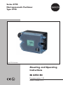
1
Series 3725 Electropneumatic Positioner Type 3725 Type 3725 Positioner Mounting and Operating Instructions EB 8394 EN Firmware version 1.10 Edition October 2012 Definition of the signal words used in these mounting and operating instructions DANGER! indicates a hazardous situation which, if not avoided, will result in death or serious injury. WARNING! indicates a hazardous situation which, if not avoided, could result in death or serious injury. 2 NOTICE indicates a property damage message. Note: Supplementary explanations, information and tips EB 8394 EN Contents 1 Safety instructions..........................................................................................6 2 Article code....................................................................................................7 3 Design and principle of operation...................................................................8 3.1 Technical data..............................................................................................10 4 Attachment to the control valve – Mounting parts and accessories..................12 4.1 4.1.1 4.1.2 Direct attachment..........................................................................................14 Type 3277-5 and Type 2780-2 Actuators.......................................................14 Type 3277 Actuator......................................................................................17 4.2 Attachment according to IEC 60534-6 (NAMUR)............................................20 4.3 Attachment to Type 3372 Actuator (V2001)....................................................23 4.4 4.4.1 Attachment to rotary actuators.......................................................................24 Mounting the Type 3710 Reversing Amplifier..................................................26 4.5 Required mounting parts and accessories........................................................27 5 Connections.................................................................................................29 5.1 5.1.1 5.1.2 Pneumatic connections..................................................................................29 Signal pressure gauges.................................................................................29 Supply pressure............................................................................................29 5.2 Electrical connections....................................................................................30 6 Operation....................................................................................................33 6.1 Operating controls........................................................................................33 7 Start-up and settings....................................................................................34 7.1 Adapting the display direction.......................................................................35 7.2 Enabling configuration..................................................................................35 7.3 Adjusting the volume restriction Q..................................................................36 7.4 Entering the opening direction/direction of action...........................................37 7.5 Entering the direction of action.......................................................................37 7.6 Limiting the signal pressure............................................................................37 7.7 Setting other parameters................................................................................38 7.8 Initialization.................................................................................................39 7.9 Zero calibration............................................................................................40 7.10 Manual mode...............................................................................................41 EB 8394 EN 3 7.11 Reset............................................................................................................42 7.12 Faults...........................................................................................................43 8 Code list......................................................................................................44 9 Maintenance................................................................................................48 10 Servicing explosion-protected devices...........................................................48 11 Dimensions in mm........................................................................................49 11.1 Fixing levels according to VDI/VDE 3845 (September 2010)...........................50 Firmware revisions 1.02 (old) 1.03 (new) Internal revisions 1.03 (old) 1.10 (new) Setting of the travel in Code P4 in steps of 0.5 mm Monitoring of the end stops only during initialization and in manual mode To suppress common-mode interference on the signal lines, the D component of the positioner is switched off when the actuator is at a standstill. 4 EB 8394 EN Safety instructions 1 Safety instructions For your own safety, follow these instructions concerning the mounting, start up and operation of the positioner: −− The device is to be assembled, started up or operated only by trained and experienced personnel familiar with the product. According to these mounting and operating instructions, trained personnel is referred to as individuals who are able to judge the work they are assigned to and recognize possible dangers due to their specialized training, their knowledge and experience as well as their knowledge of the applicable standards. −− Explosion-protected versions of this device are to be operated only by personnel who has undergone special training or instructions or who is authorized to work on explosion-protected devices in hazardous areas. −− Any hazards that could be caused in the valve by the process medium, the signal pressure or by moving parts are to be prevented by means of the appropriate measures. −− If inadmissible motions or forces are produced in the pneumatic actuator as a result of the supply pressure level, it must be restricted using a suitable supply pressure reducing station. −− Proper shipping and storage are assumed. To avoid damage to any equipment, the following also applies: −− Do not operate the positioner with the back of the positioner/vent opening facing upwards. The vent opening must not be sealed when the positioner is installed on site. Vent opening Note: Positioners with a CE marking fulfill the requirements of the Directives 2004/108/EC and 2006/95/EC. The Declaration of Conformity is available on request. 6 EB 8394 EN Article code 2 Article code Positioner Type 3725- x x x 0 0 0 0 0 0 0 9 9 9 9 With LCD and autotune, 4 to 20 mA reference variable Explosion protection 1) Without II 2 G Ex ia IIC T4 acc. to ATEX 0 0 0 1 1 0 0 Other certification is pending 1) EB 8394 EN 7 Design and principle of operation 3 Design and principle of operation The electropneumatic positioner is mounted on pneumatic control valves and is used to assign the valve position (controlled variable x) to the control signal (reference variable w). The positioner compares the electric control signal of a control system to the travel or opening angle of the control valve and issues a signal pressure (output variable y) for the pneumatic actuator. The positioner mainly consists of the following components (see Fig. 1): −− Anisotropic magnetoresistive (AMR) sensor (2) −− Analog i/p converter (6) with a downstream air capacity booster (7) −− Electronics unit with microcontroller (4) the actuator of the control valve (1) is pressurized or vented accordingly over the downstream booster (7). The supply air is supplied to the booster and the pressure regulator (8). The output signal pressure supplied by the booster can be limited to 2.4 bar by software. The volume restriction Q (10) is used to optimize the positioner by adapting it to the actuator size. Tight-closing function The pneumatic actuator is completely filled with air or vented as soon as the reference variable falls below 1 % or exceeds 99 % (see end positions set in P10 and P11 parameter codes). Air to open (ATO): P10 –> ON; P11 –> OFF Air to close (ATC): P10 –> OFF; P11 –> ON The travel or opening angle is measured by the pick-up lever connected to a magnet and a non-contact AMR sensor (2) installed in the positioner and the downstream electronics. The motion of the pick-up lever causes the direction of the magnetic field to change. This change is sensed by the AMR sensor. The electronics unit determines the current valve position or opening angle from this information. The position of the valve is transmitted to the microcontroller (4) over its A/D converter (3). The PD control algorithm in the microprocessor compares this actual position to the 4 to 20 mA control signal (reference variable) after it has been converted by the A/D converter (3). In case of a system deviation, the activation of the i/p converter (6) is changed so that 8 EB 8394 EN Design and principle of operation 11 S mm % % mm 5 w 3 4 2 6 9 8 7 1 2 3 4 5 6 Control valve AMR sensor A/D converter Microcontroller D/A converter i/p converter 7 Air capacity booster 8 Pressure regulator 9 Fixed restriction 10 Volume restriction 11Display Q 10 y 1 x Fig. 1: Functional diagram EB 8394 EN 9 Design and principle of operation 3.1 Technical data Positioner Direct attachment to Type 3277: Direct attachment to Type 2780-2: Attachment to Type 3372 Actuator: Attachment according to IEC 60534-6 (NAMUR): Attachment to rotary actuators: Reference variable w 4 to 20 mA signal range · Two-wire device with reverse polarity protection Split-range operation 4 to 11.9 mA and 12.1 to 20 mA Static destruction limit 33 V Power consumption (start-up) 3.8 mA Power consumption (operation) 3.6 mA 3.75 to 30 mm 6/12/15 mm 15/30 mm 3.75 to 50 mm 24 to 100° Load impedance Max. 6.3 V Supply air Air quality acc. to ISO 8573-1 Supply air: 1.4 to 7 bar (20 to 105 psi) Max. particle size and density: Class 4 · Oil content: Class 3 · Pressure dew point: Class 3 or at least 10 K below the lowest ambient temperature to be expected Signal pressure (output) 0 bar up to the capacity of the supply pressure · Can be limited to approx. 2.4 bar by software Characteristic 3 characteristics for globe valves · 9 characteristics for rotary valves Hysteresis ≤ 0.3 % Sensitivity ≤ 0.1 % Transit time Only for actuators with initialization time > 0.5 s 1) Direction of action w/x reversible Air consumption ≤ 100 ln/h with a supply pressure up to 6 bar and a signal pressure of 0.6 bar Air output capacity Actuator filled with air Actuator vented At Δp =6 bar: 8.5 mn3/h, At Δp =6 bar: 14.0 mn3/h, Permissible ambient temperature –20 to +80 °C · –25 to +80 °C with metal cable gland The limits in the test certificate additionally apply for explosion-protected versions Influences Temperature: Vibrations: Supply air: 1) Travel, adjustable At Δp =1.4 bar: 1.4 mn3/h At Δp =1.4 bar: 4.5 mn3/h KVmax(20 °C) = 0.09 KVmax(20 °C) = 0.15 ≤ 0.15 %/10 K ≤ 0.5 % up to 2000 Hz and 4 g according to IEC 770 None For faster actuators, a volume restriction must be used. Otherwise, the initialization cannot be performed successfully. 10 EB 8394 EN Design and principle of operation Electromagnetic compatibility Explosion protection Degree of protection Complying with EN 61000-6-2, EN 61000-6-3 and NAMUR Recommendation NE 21 II 2 G Ex ia IIC T4 IP 66 Materials Body Polyphthalamide (PPA) Cover Polycarbonate (transparent) External parts Stainless steel 1.4571 and 1.4301 Cable gland M20x1.5, black polyamide Venting High-density polyethylene (PE-HD) Weight Approx. 0.5 kg EB 8394 EN 11 Attachment to the control valve – Mounting parts and accessories 4 Attachment to the control valve – Mounting parts and accessories NOTICE Attach the positioner, keeping the following sequence: 1. Mount the positioner on the control valve 2. Connect the supply air 3. Connect the electrical power 4. Perform the start-up settings The positioner is suitable for the following types of attachment: −− Direct attachment to SAMSON Type 3277 and Type 2780-2 Actuators −− Attachment according to IEC 60534-6 (NAMUR) −− Attachment to Type 3372 Actuator (Series V2001 Valves) −− Attachment to rotary actuators acc. to VDI/VDE 3845 NOTICE −−Attach the positioner to the control valve only using the mounting parts and accessories as described in section 4.5. −−Observe the type of attachment! −−Observe the assignment between lever and pin position! The travel tables show the maximum adjustment range at the positioner. The travel that can be implemented at the valve is additionally restricted by the selected fail-safe position and the required compression of the actuator springs. The positioner is equipped with the lever M (pin position 35) as standard. Fig. 2: Lever M with pin position 35 NOTICE Only remove the lever when it is positioned in the bottom mechanical stop. Otherwise, the internal stops may be damaged. Removing the lever 1. Hold the lever in place. Undo the nut using a wrench (width across flats SW 10). 2. Remove the lever from the shaft. Top stop Lever and pin position The positioner is adapted to the actuator and to the rated travel by the lever on the back of the positioner and the pin inserted into the lever. 12 Bottom stop Fig. 3: Mechanical stops for lever EB 8394 EN Attachment to the control valve – Mounting parts and accessories Travel tables Note: The lever M is included in the scope of delivery. Direct attachment to Type 3277-5 and Type 3277 Actuators Actuator size Rated travel [cm²] [mm] Adjustment range at positioner Min. Travel Max. Required lever Assigned pin position 120 7.5 5.0 to 16.0 M 25 120/240/350 15 7.0 to 22.0 M 35 355/700 30 10.0 to 32.0 M 50 Required lever Assigned pin position Direct attachment to Type 2780-2 Actuator Actuator size Rated travel Adjustment range at positioner [cm²] [mm] Min. Travel Max. 120 6/12 5.0 to 16.0 M 25 120 15 7.0 to 22.0 M 35 Required lever Assigned pin position Attachment according to IEC 60534-6 (NAMUR) SAMSON Type 3271 Actuator Travel of other valves [mm] Size [cm²] Rated travel [mm] Min. Max. 120 7.5 3.5 11.0 S 17 120 7.5 5.0 25.0 M 25 7.0 35.0 M 35 10.0 50.0 M 50 120/240/350 15 700 7.5 700 15/30 Attachment to rotary actuators acc. to VDI/VDE 3845 Rotary actuators Min. Opening angle Max. 24° to 100° EB 8394 EN Required lever Assigned pin position M 90° 13 Attachment to the control valve – Mounting parts and accessories 4.1 Direct attachment 4.1.1 Type 3277-5 and Type 2780-2 Actuators Refer to Table 1 on page 27 for the requiredmountingpartsandaccessories. Observethetraveltableonpage13. Actuator with 120 cm² mountingscrewislocatedinthegrooveof theactuatorstem. 4. 15mmtravel:Keepthefollowerpin(2) onleverM(1)onthebackofthepositionerinthepinposition35(deliveredstate). 7.5mmtravel:Removethefollowerpin (2)fromthepinposition35,repositionit intheholeforpinposition25andscrew tight. 5. Insertformedseal(15)intothegrooveof Dependingonthetypeofpositionerattachthepositionerhousing. ment,thesignalpressureisroutedeitherleft 6. Placepositionerontheactuatorinsucha orrightoftheyokethroughaholetotheacmannerthatthefollowerpin(2)restson tuatordiaphragm. topofthefollowerclamp(3).WhiledoDependingonthefail-safeactionoftheacingthis,pressontheribbedareashown tuator"Actuatorstemextends"or"Actuator inFig.4tolockthepick-upleverinthetop stemretracts"(valveclosesoropensifthesupposition.Thelever(1)mustrestonthefolplyairfails),theswitchoverplate(9)mustfirst lowerclampwithspringforce. beattachedtotheactuatoryoke.Alignthe switchoverplatewiththecorrespondingsymbolforleftorrightattachmentaccordingto themarking(viewlookingontotheswitchoverplate). 1. Mount connecting plate (6) or pressure gaugebracket(7)withpressuregauges ontothepositioner,makingsurebothseal rings(6.1)areseatedproperly. 2. Screwthescrewplug(4)onthebackof thepositionerintotheholebelowit(park position)(seeFig.7)andsealthesignal pressure output on the connecting plate (6)oronthepressuregaugebracket(7) with the stopper (5) included in the accessories. Fig. 4: Locking the pick-up lever in position Mountthepositionerontheactuatorusing thetwofixingscrews. 3. Place follower clamp (3) on the actuatorstem,alignandscrewtightsothatthe 14 EB 8394 EN Attachment to the control valve – Mounting parts and accessories Symbols 1 Lever 1.1Nut 1.2Diskspring 2 Follower pin 3 Follower clamp 4 Screwplug 5 Stopper 6 Connectingplate 6.1 Seal 7 Pressuregauge bracket 8 Pressuregauge mountingkit 9 Switchover plate (actuator) 11 Cover 15 Formed seal 16 Ventplug Switchoverplate(9) Actuatorstem extends Leftattachment Rightattachment Actuatorstem retracts Signalpressure inputforleftattachment Marking Signalpressure inputforright attachment 15 1 2 3 1.1 1.2 16 4 6.1 6 5 Supply 9 9 Output 38 Note: Always use the connecting plate (6) or pressure gauge bracket (7) included in the accessories to connect supply and output. Never screw threaded parts directly into the housing. Otherwise, the filter will be damaged! 11 7 8 Fig. 5: Direct attachment – Signal pressure connection for Type 3277-5 Actuator with 120 cm² EB 8394 EN 15 Attachment to the control valve – Mounting parts and accessories 7. Mount cover (11) on the other side. Make sure that the vent plug is located at the bottom when the control valve is installed to allow any condensed water that collects to drain off (Fig. 6). Additional solenoid valve If a solenoid valve is additionally mounted onto the actuator, the signal pressure port at the back of the positioner must be sealed. To do this, unscrew the screw plug located in the middle hole (screw plug in park position) and screw it into the signal pressure port to seal it. Screw plug (4) (signal pressure port) Park position Cover Fastening screw Vent plug Fig. 6: Cover with venting when the valve is installed Fig. 7: Signal pressure port and park position for screw plug In this case, the signal pressure must be routed from the signal pressure output to the actuator over the connecting plate (6) or pressure gauge bracket (7). The connecting plate (accessories for the actuator) replaces the switchover plate (9). 16 Note: The switchover plate or connecting plate are accessories for the actuator (120 cm²) listed in the table on page 27. EB 8394 EN Attachment to the control valve – Mounting parts and accessories 4.1.2 Type 3277 Actuator Refer to section 4.5 for the required mounting parts and accessories. Observe the travel table on page 13. Note: The actuators with 240 to 700 cm² effective areas are described on the following pages. Fig. 8: Type 3372 Actuator with Type 3725 Positioner (direct attachment) EB 8394 EN 17 Attachment to the control valve – Mounting parts and accessories Actuators with 240 to 700 cm² effective areas The positioner can be mounted either on the left or right side of the yoke. The signal pressure is routed to the actuator over the connection block (12), for actuators with failsafe action "Actuator stem extends" internally through a hole in the valve yoke and for "Actuator stem retracts" through an external pipe. 1. Place follower clamp (3) on the actuator stem, align and screw tight so that the mounting screw is located in the groove of the actuator stem. 2. For actuators 240 and 350 cm² with 15 mm travel, keep the follower pin (2) in pin position 35. For actuators with 355 or 700 cm², remove the follower pin (2) on lever M (1) on the back of the positioner from pin position 35, reposition it in the hole for pin position 50 and screw tight. the actuator symbol that corresponds with the actuator with fail-safe action "Actuator stem extends" or "Actuator stem retracts". If necessary, remove the three mounting screws and the cover. Then reposition the gasket (16) turned by 180°. 6. Place the connection block (12) with the associated seals against the positioner and the actuator yoke and fasten using the screw (12.1). For actuators with fail-safe action "Actuator stem retracts", additionally remove the stopper (12.2) and mount the external signal pressure pipe. 7. Mount cover (11) on the other side. Make sure that the vent plug is located at the bottom when the control valve is installed to allow any condensed water that collects to drain off (see Fig. 6 on page 16). 3. Insert formed seal (15) in the groove of the positioner housing. 4. Place positioner on the actuator in such a manner that the follower pin (2) rests on top of the follower clamp (3). While doing this, press on the ribbed area to lock the pick-up lever in the top position (see Fig. 4 on page 14). The lever (1) must rest on the follower clamp with spring force. Mount the positioner on the actuator using the two fixing screws. 5. Check to make sure that the tip of the gasket (16) projecting from the side of the connection block (12) is positioned above 18 EB 8394 EN Attachment to the control valve – Mounting parts and accessories 1 Lever M 1.2 Nut 1.2 Disk spring 2 Follower pin 3 Follower clamp 11 Cover 12 Connection block 12.1Screw 12.2 Stopper or connection for external piping 15 Formed seal 16 Gasket 10 15 1 2 3 11 2 1 1.1 1.2 View A A Ansicht 16 16 SUPPLY 12 12.1 12.2 A Fig. 9: Direct attachment – Signal pressure connection for Type 3277 Actuator with 240 to 700 cm² EB 8394 EN 19 Attachment to the control valve – Mounting parts and accessories 4.2 Attachment according to IEC 60534-6 (NAMUR) The positioner is attached to the control valve using a NAMUR bracket (10). Refer to Table 3 on page 27 for the required mounting parts and accessories. Observe the travel table on page 13. 1. Screw the two bolts (14) to the bracket (9.1) of the stem connector (9), place the follower plate (3) on top and use the screws (14.1) for fastening. 2. Mount NAMUR bracket (10) using the M8 screw (11) and toothed lock washer directly to the yoke hole. Align the NAMUR bracket (10) so that its mounting holes are approximately in line with the middle of the travel scale indicator (15) (the slot of the follower plate must be centrally aligned with the NAMUR bracket at mid valve travel). 3. Mount connecting plate (6) or pressure gauge bracket (7) with pressure gauges (8) on the positioner, making sure the two seals (6.1) are seated properly. 4. Place positioner on the NAMUR bracket in such a manner that the follower pin (2) rests in the slot of the follower plate (3). Adjust the lever (1) correspondingly. Screw the positioner to the NAMUR bracket using both its mounting screws. 20 EB 8394 EN Attachment to the control valve – Mounting parts and accessories 15 11 10 9 9.1 14 3 14.1 2 1 1.1 1.2 2 3 6 6.1 7 Lever Nut Disk spring Follower pin Follower plate Connecting plate Seal Pressure gauge bracket 8 Pressure gauge 9 Stem connector 9.1 Bracket 10 NAMUR bracket 11Screw 14Bolt 14.1Screws 15 Travel indicator scale 1.1 1.2 6.1 6 7 8 1 Fig. 10:Attachment according to IEC 60534-6 (NAMUR) EB 8394 EN 21 Attachment to the control valve – Mounting parts and accessories 22 EB 8394 EN Attachment to the control valve – Mounting parts and accessories 4.3 Attachment to Type 3372 Actuator (V2001) The Type 3725 Positioner is already included in the scope of delivery for Series V2001 Valves (Type 3372 Actuator). The attachment is briefly described below to allow conversion work to be performed. Actuator with 120/350 cm², stem extends The signal pressure is routed through the corresponding port in the support element to the actuator diaphragm. Thread the screw plug on the positioner into the hole below (park position) (see Fig. 7 on page 16). Type 3372 Actuator, version 120 cm² effective area Actuator with 120/350 cm², stem retracts The signal pressure is routed through piping at the side of the support element to the actuator diaphragm. Attachment including solenoid valve The signal pressure is routed from the output port of the positioner to the solenoid valve and through a corresponding hole in the support element to the actuator diaphragm. Type 3372 Actuator, version 350 cm² effective area Fig. 11:Mounting on Type 3372 Actuator EB 8394 EN 23 Attachment to the control valve – Mounting parts and accessories 4.4 Attachment to rotary actuators The positioner is mounted to the rotary actuator using a mounting bracket. Refer to Table 4 on page 28 for the required mounting parts and accessories. Before attaching the positioner onto the SAMSON Type 3278 Rotary Actuator (160 cm²) or VETEC Type S160 Actuator, first mount the adapter (13) to the free end of the shaft end using four screws (11, 12). NOTICE On attaching the positioner as described below, it is imperative that the actuator's direction of rotation is observed. 6. Unscrew the standard follower pin (2) from the positioner's lever M (1). Use the metal follower pin (Ø 5 mm) included in the mounting kit and screw tight into the hole for pin position 90°. 7. Place positioner on the mounting bracket (10) and screw tight. Taking the actuator's direction of rotation into account, adjust lever (1) so that it engages in the slot of the coupling wheel (4) with its follower pin (Fig. 13). It must be guaranteed that the lever (1) is parallel to the long side of the positioner when the actuator is at half its angle of rotation. 8. Stick the scale label on the coupling wheel (4) so that the arrow tip indicates the closed position and it can be easily read when the valve is installed. 1. Place follower clamp (3) on the slotted actuator shaft or adapter (13). 2. Place coupling wheel (4) with flat side facing the actuator on the follower clamp (3). Refer to Fig. 12 to align slot so that it matches the direction of rotation when the valve is in its closed position. 3. Fasten the coupling wheel (4) and follower clamp (3) tightly onto the actuator shaft using screw (4.1) and disk spring (4.2). 4. Mount connecting plate (6) or pressure gauge bracket (7) with pressure gauges (8) on the positioner, making sure the two seals are seated properly. 5. Fasten the mounting bracket (10) to the actuator using four screws (10.1). 24 Fig. 12:Direction of rotation EB 8394 EN Attachment to the control valve – Mounting parts and accessories 6 6.1 7 8 1 1.1 1.2 1 Lever 1.2 Nut 1.2 Disk spring 2 Follower pin 3 Follower clamp 4 Coupling wheel 4.1Screw 4.2 Disk spring 5 Actuator shaft 6 Connecting plate 6.1 Seal 7 Pressure gauge bracket 8 Pressure gauge mounting kit 10 Mounting bracket 10.1Screws 13 Adapter 6 6.1 7 8 2 4.1 4.2 4 1 1.1 1.2 3 2 10.1 4.1 4.2 4 3 50 80 10 10.1 10.1 80 10 50 13 30 60 5 30 Attachment to VETEC Type S160 Actuator or SAMSON Type 3278 Rotary Actuator, 160 cm² 5 Attachment according to VDI/VDE 3845, level 1 Fig. 13:Attachment to rotary actuators EB 8394 EN 25 Attachment to the control valve – Mounting parts and accessories 4.4.1 Mounting the Type 3710 Reversing Amplifier When a Type 3710 Reversing Amplifier is used, a connecting plate must be installed between the positioner and reversing amplifier. The reversing amplifier is fastened to the positioner together with the connecting plate using screws (Fig. 14). Refer to the Mounting and Operating Instructions of the Type 3710 Reversing Amplifier: u EB 8392 EN Connecting plate Type 3710 Reversing Amplifier M5 screws Fig. 14:Mounting the Type 3710 Reversing Amplifier 26 EB 8394 EN Attachment to the control valve – Mounting parts and accessories 4.5 Required mounting parts and accessories Table 1: Direct attachment to Types 3277-5 and 3277 Actuators (section 4.1) Mounting parts Accessories for actuator Mounting parts for actuators with 120 cm² effective area or smaller 1402-0239 Switchover plate for Type 3277-5xxxxxx.01 Actuator 1400-6822 Connecting plate for additional attachment, e.g. solenoid valve: G 1/8 Connecting plate (6) Accessories for positioner Pressure gauge bracket (7) Pressure gauge mounting kit (8), up to max. 6 bar (output/supply) 1402-0235 ¼ NPT 1402-0236 G¼ 1402-0237 ¼ NPT 1402-0238 St. steel/brass 1400-6950 St. steel/st. steel 1400-6951 Order no. Attachment to actuators with 240, 350, 355 and 700 cm² Connection block with seals and screw Accessories Pressure gauge mounting kit up to max. 6 bar (output/supply) 1400-6820 G¼ Table 2: Direct attachment to Type 3277 Actuator (section 4.1.2) Mounting parts Order no. 1402-0240 G¼ 1402-0241 ¼ NPT 1402-0242 St. steel/brass 1400-6950 St. steel/st. steel 1400-6951 Table 3: Attachment to NAMUR ribs according to IEC 60534-6 (section 4.2) Travel [mm] Lever For actuators 3.75 to 50 Without, already on positioner Actuators from other manufacturers and Type 3271 with 120 to 700 cm² effective areas Connecting plate Accessories Pressure gauge bracket Pressure gauge mounting kit up to max. 6 bar (output/supply) EB 8394 EN Order no. 1402-0330 G¼ 1402-0235 ¼ NPT 1402-0236 G¼ 1402-0237 ¼ NPT 1402-0238 St. steel/brass 1400-6950 St. steel/st. steel 1400-6951 27 Attachment to the control valve – Mounting parts and accessories Order no. Table 4: Attachment to rotary actuators (section 4.4) Mounting parts Attachment acc. to VDI/VDE 3845, size AA1 (see dimension table on page 50) 1402-0243 Attachment acc. to VDI/VDE 3845, size AA2 (see dimension table on page 50) 1402-0244 Attachment to VETEC Type S160 Actuator or SAMSON Type 3278 Rotary Actuator, 160 cm² (level 2) 1) 1402-0294 Connecting plate Accessories Pressure gauge bracket Pressure gauge mounting kit up to max. 6 bar (output/supply) Connecting plate for Type 3710 Reversing Amplifier G¼ 1402-0235 ¼ NPT 1402-0236 G¼ 1402-0237 ¼ NPT 1402-0238 St. steel/brass 1400-6950 St. steel/st. steel 1400-6951 1402-0512 Refer to section 11.1 on page 50 for details 1) Table 5: General accessories Plastic cable gland, M20x1.5 Adapter M20x1.5 to ½ NPT Brief instructions inside cover 28 Order no. Black 8808-1011 Blue 8808-1012 Nickel-plated brass 1890-4875 Stainless steel 1.4305 8808-0160 Powder-coated aluminum 0310-2149 Stainless steel 1400-7114 DE/EN (delivered state) 0190-6173/ 0190-6174 EB 8394 EN Connections 5 Connections tor's fail-safe action "Actuator stem extends" or "Actuator stem retracts". 5.1 Pneumatic connections For rotary actuators, the manufacturer's specifications for connection apply. NOTICE The threaded connections in the positioner housing are not designed for the direct connection of pneumatic fittings! The screw fittings must be screwed into the connecting plate, the pressure gauge mounting block or the connection block from the accessories. Their pneumatic connections are optionally designed as a bore with ¼ NPT or G ¼ thread. The customary fittings for metal and copper pipes or plastic hoses can be used. Keep the length of the line as short as possible to avoid delays in control signal transmission. NOTICE The supply air must be dry and free from oil and dust. The maintenance instructions for upstream pressure reducing stations must be observed. Blow through all air pipes and hoses thoroughly prior to connecting them. 5.1.1 Signal pressure gauges To monitor the supply air (supply) and signal pressure (output), we recommend mounting pressure gauges (see accessories in section 4.5). 5.1.2 Supply pressure The required supply air pressure depends on the bench range and the actuator's operating direction (fail-safe action). The bench range is registered on the nameplate either as spring range or signal pressure range depending on the actuator. The direction of action is marked FA or FE, or by a symbol. Actuator stem extends FA (air to open) Fail-safe position "Valve Closed" (for globe and angle valves): Required supply pressure = Upper bench range value + 0.2 bar, minimum 1.4 bar. The signal pressure connection is fixed when the positioner is directly attached to the Type 3277 Actuator. For attachment according to IEC 60534-6 (NAMUR), the signal pressure can be routed to either the top or bottom diaphragm chamber of the actuator, depending on the actua- EB 8394 EN 29 Connections Actuator stem retracts FE (air to close) Fail-safe position "Valve Open" (for globe and angle valves): For tight-closing valves, the maximum signal pressure pstmax is roughly estimated as follows: pstmax ==F + d d² · π · ∆p 4·A [bar] =Seat diameter [cm] ∆p =Differential pressure across the valve [bar] A =Actuator diaphragm area [cm²] F =Upper bench range value [bar] If there are no specifications, calculate as follows: Required supply pressure = Upper bench range value + 1 bar Note: The signal pressure at the output (38) of the positioner can be restricted to approx. 2.4 bar by setting P9 parameter code to ON. 5.2 Electrical connections DANGER! Risk of electric shock and/or the formation of an explosive atmosphere! −−For electrical installation, observe the relevant electrotechnical regulations and the accident prevention regulations that apply in the country of use. The following regulation applies to mounting and installation in hazardous areas: EN 60079-14: Explosive atmospheres – Part 14: Electrical installations design, selection and erection. −−Avoid electrostatic charging of the plastic housing when mounting and servicing the positioner in hazardous areas. NOTICE −−Do not loosen enameled screws in or on the housing. −−The maximum permissible values (Ui, Ii, Pi, Li and Ci) specified in the EC-type examination certificate apply when interconnecting intrinsically safe electrical equipment). NOTICE Only a current source must be used for the electrical supply. Do not use a voltage source! 30 EB 8394 EN Connections Selecting cables and wires Observe EN 60079-14 and particularly Clause 12 in it when installing intrinsically safe circuits. Notch on plastic part The Subclause 12.2.2.7 applies when running multi-core cables containing more than one intrinsically safe circuit. The minimum radial thickness of the conductor insulation must be suitable for the conductor diameter and type of insulation. It must be at least 0.2 mm. The diameter of an individual wire in a finestranded conductor must not be smaller than 0.1 mm. Protect the conductor ends against splicing, e.g. by using wire-end ferrules. Equipment for use in zone 2 In equipment operated with type of protection Ex nA (non-sparking equipment) according to EN 60097-15, circuits may be connected, interrupted or switched while energized only during installation, maintenance or repair. Cable entry The M20 x 1.5 cable gland is designed for a clamping range of 6 to 12 mm. The cage clamp terminals hold wire cross-sections of 0.2 to 1.5 mm² and additionally have test connections for 1 mm probe tips. EB 8394 EN Fig. 15:Cage clamp terminal NOTICE Applying excessive force to the cage clamp terminals may damage them. The test connections are also used to unlock the cage clamp terminals: place a slotted screwdriver on the notch of the plastic part of the test connection (Fig. 15) and press down, while inserting or removing the wire. The wires for the reference variable must be connected to the terminals 11 and 12 located in the housing. NOTICE The static destruction limit of the positioner is at ± 33 V. Do not allow the input signal to fall below the lowest permissible value of 3.8 mA for positioner operation. 31 Connections Accessories: Plastic cable gland, M20 x 1.5 −− Black Order no. 8808-1011 −− Blue Order no. 8808-1012 −− Nickel-plated brass Order no. 1890-4875 −− Stainless steel 1.4305 Order no. 8808-0160 Adapter M20x1.5 to ½ NPT −− Powder-coated aluminum Order no. 0310-2149 −− Stainless steel +11 Order no. 1400-7114 -12 mA control signal Fig. 16:Electrical connections 32 EB 8394 EN Operation 6 Operation NOTICE Any parameter code settings that have been changed are first saved in a nonvolatile memory after the display has returned to the display with status indication. Go to Code P0 by touching or or wait three minutes until the display returns automatically. The icon on the display indicates that the changed parameter settings have not yet been saved in the nonvolatile memory. Three capacitive keys and a LCD are used to operate the positioner (see below). To adapt the air capacity, the volume restriction must be adjusted (section 7.3). 6.1 Operating controls Touch or to select a parameter code (P0 to P20). Then touch to confirm the selected code. Note: After changing settings in P2, P3, P4, P8 and P9 parameter codes, the positioner must be re-initialized. Confirm Down Up Operation locked % Fail-safe position active mm Parameter/error code Settings not yet saved in a non-volatile memory S mm % Unit Bar graph for system deviation Fault Manual mode Closed-loop operation Fig. 17:Capacitive keys and display EB 8394 EN 33 Start-up and settings Volume restriction Q The volume restriction serves to adapt the air output capacity to the size of the actuator. Two fixed settings are possible (refer to section 7.3). 7 Start-up and settings WARNING! Do not perform a start-up while the process is running. On applying supply air and the electric control signal, the control valve may move through its entire travel range/rotational angle range depending on the setting. Display Display Meaning ESC Cancel Err Error LOW w too low MAN Manual mode MAX Maximum range RST Reset INIT Initialization ON/OFF Activated/deactivated ZERO Zero calibration −− Connect the supply air (Supply 9). −− Connect the 4 to 20 mA signal (terminals +11/–12). Icons assigned to certain codes and functions are indicated on the display. The bar elements indicate the system deviation that depends on the sign (+/–) and the value. One bar element appears per 1 % system deviation. If the positioner has not yet been initialized, the lever position in degrees in relation to the longitudinal axis is indicated. One bar element corresponds to approximately a 7° angle of rotation. If the fault indication icon appears on the display, touch or until ERR appears on the display to view the E0 to E15 error code(s) (see code list in section 8). 34 Note: After connecting the electrical signal (power supply), the positioner performs a calibration of the capacitive keys which takes approx. three seconds. During this time, do not touch the key panel. Otherwise, the keys will not work properly. Disconnect and reconnect the electrical signal to restart the calibration of keys. LOW on the display indicates that the reference variable is lower than 3.6 mA. The positioner is ready for operation with its default settings for most applications, provided it has been mounted properly. Note: The positioner needs to be initialized again after the position of the volume restriction has been changed. The positioner also needs to be initialized again after the setting for the fail-safe position has been changed. EB 8394 EN Start-up and settings Reading after connecting the electrical signal 7.2 Enabling configuration The fault indication icon and und S (fail-safe position) appear on the display when the positioner has not yet been initialized. The reading indicates the lever positioner in degrees relative to the longitudinal axis. S Enabling configuration with Code 19 Reading when the positioner has not yet been initialized If no settings are entered within three minutes, the enabled configuration function becomes invalid. Touch or until Code P19 appears. −− Code P0 appears on the display after connecting the electrical signal to an initialized positioner. 7.1 Adapting the display direction The data representation on the positioner display can be turned by 180°. If the displayed data appear upside down, proceed as follows: Touch or until Code P1 appears. Touch to confirm the selected code. P1 blinks. Reading direction for right attachment of pneumatic connections Touch or until until the display is set in the desired direction. Touch Note: Before changing parameter settings, configuration must be enabled first by selecting Code P19. Touch blinks. to confirm the selected code. P19 Touch until OPEN appears on the display. Touch to unlock operation. NOTICE During start-up, the actuator stem moves. Do not touch the actuator stem or obstruct it to avoid risk of injury to hands or fingers. The permissible range has been exceeded when the displayed angle is more than 30°. The positioner goes to the fail-safe position (SAFE). Make sure that the lever and pin position match the details as described in section 4. to confirm display direction. EB 8394 EN 35 Start-up and settings Note: The positioner has a function to monitor the working range. If the lever moves too close to the mechanical stops (risk of mechanical damage), the positioner vents the actuator and the valve moves to its failsafe position (S displayed together with E8 error code). In this case, check the positioner attachment. Reset the displayed error code by selecting RST (see section 7.11). 7.3 Adjusting the volume restriction Q Fig. 18: Volume restriction Q MAX/MIN setting ThevolumerestrictionQservestoadaptthe airoutputcapacitytothesizeoftheactuator: − Actuatorswithatransit time < 1 s,e.g. linear actuators with an effective area smallerthan240 cm²,requirearestrictedairflowrate. SettingtoMIN − Actuatorswithatransit time ≥ 1 s do not requiretheairflowratetoberestricted. SettingtoMAX Intermediatesettingsarenotpermitted. NOTICE The positioner needs to be initialized again after the position of the restriction has been changed. 36 EB 8394 EN Start-up and settings 7.4 Entering the opening direction/direction of action For checking purposes: Aftersuccessfullycompletinginitialization,the positionerdisplayshouldread0 %whenthe − AIRTOOPEN(ATO)appliestoavalve valveisclosedand100 %whenthevalveis openingasthesignalpressureincreases. open. − AIRTOCLOSE(ATC)appliestoavalve If necessary, the direction of action can be closingasthesignalpressureincreases. changedeitherbeforeorafterinitialization. Thesignalpressureisthepneumaticpressure Thefollowingcorrelationapplies: attheoutputofthepositionerappliedtothe Valve CLOSED actuator. Enableconfiguration(section7.2). Reading ATO ATC Default ATO Touch Touch or untilCodeP2 appears. 7.5 100% >> 4mA 20mA <> 20mA 4mA >> 4mA 20mA <> 20mA 4mA >> Increasing/increasing <> Increasing/decreasing toconfirmselectedcode.P2blinks. Touch or untiltherequiredfail-safeposition appears. Touch OPEN 0% toconfirmsetting. Note: The changed opening direction/direction of action first becomes effective after the positioner has been reinitialized. 7.6 Limiting the signal pressure If the maximum actuator force may cause damagetothevalve,thesignalpressuremust belimited.SetCodeP9toON.Thislimitsthe signalpressuretoapprox.2.4 bar. Enableconfigurationatthepositionerbefore activatingthepressurelimitfunction(seesection7.2). Entering the direction of action Thedirectionofaction(P7)issettoincreasing/increasingbydefault. EB 8394 EN 37 Start-up and settings 7.7 Setting other parameters The following table lists all the parameter codes and their default settings. If you want to change the default setting of a parameter, proceed in the same manner as previously described. Note: The selected parameter code remains active until you change the setting or exit the parameter code. Parameter codes [Default setting] Codes marked with * indicate that the positioner needs to be re-initialized afterwards P17 Manual mode P18 Reset P19 Enable configuration P20 Read firmware More details concerning the parameter codes can be found in section 8. Parameter codes [Default setting] Codes marked with * indicate that the positioner needs to be re-initialized afterwards P0 Operation P1 Reading direction P2* Fail-safe position [ATO] P3* Pin position [35] P4* Nominal range [MAX] P5 Characteristic [1] P6 Reference variable [4 to 20 mA] P7 w/x direction of action [>>] P8* Gain Kp [50] P9 Pressure limit 2.4 bar [OFF] P10 End position w < [ON] P11 End position w > [OFF] P14 Display of reference variable w P15 INIT Start initialization P16 ZERO Start zero calibration 38 EB 8394 EN Start-up and settings 7.8 Initialization During initialization the positioner adapts itself optimally to the friction conditions and the signal pressure required by the control valve. WARNING! During the initialization, the control valve moves through its entire travel range/angle of rotation. Therefore, do not start initialization while a process is running, but only during start-up, when all shut-off valves are closed. Touch Initialization starts. INIT blinks on the display! MAX is the default setting for the nominal range (Code P4). Alternatively, a different travel can be selected in Code P4 (see code list in section 8). Note: The travel set in Code P4 is only limited during initialization. However, it might be exceeded in closed-loop control when the control signal is higher than 20 mA. Start initialization by activating Code P15 as follows: to select Code P15. Touch six seconds long. 6-5-4-3-2-1- is counted down on the display. The type and extent of self-adaptation depends on the preset parameters. During the initialization process, the positioner determines the travel range/angle of rotation of the valve (from the CLOSED position to the other end position). or Note: The time required for the initialization procedure depends on the actuator transit time and can take a few minutes. % Initialization successfully completed, positioner runs in closed-loop operation After a successful initialization, the position% er runs in closed-loop operation indicated by the closed-loop operation icon and control position in % predetermined by the reference variable on the display. Configuration is locked. A malfunction leads to the process being interrupted and the positioner moving to the fail-safe position. The fault indication icon appears on the display. Refer to section 7.12. S Initialization canceled EB 8394 EN 39 Start-up and settings Canceling initialization The initialization can be canceled by touching . 7.9 Zero calibration In case of inconsistencies in the closing position of the valve, e.g. with soft-seated plugs, it might be necessary to recalibrate zero. Enable configuration as described in section 7.2. Start the zero calibration by activating Code P16 as follows: −− ESC blinks on the display. −− Touch to confirm. Note: This code must be confirmed by touching . Otherwise, the code remains active. Case 1: A positioner that has not yet been initialized goes to the fail-safe position after the initialization process has been canceled. Case 2: The initialized positioner goes to AUTO mode after the re-initialization process has been canceled. The settings of the previous initialization are used. A new initialization can be started directly afterwards. 40 Touch or until Code P16 appears. Touch six seconds long. 6-5-4-3-2-1- is counted down on the display. Zero calibration starts, the display blinks! The positioner moves the control valve to the CLOSED position and recalibrates the internal electric zero point. When the zero calibration has been successfully completed, the positioner returns to closed-loop operation (display with status indication). EB 8394 EN Start-up and settings Canceling zero calibration The zero calibration can be canceled by touching . 7.10Manual mode The valve position can be moved as follows using the Manual mode function: Enable configuration (section 7.2). Touch or until Code P17 appears. Touch six seconds long. 6-5-4-3-2-1- is counted down on the display. −− ESC blinks on the display. −− Touch to confirm. P17 blinks. The manual set point (w man) is indicated on the display of an initialized positioner. Note: This code must be confirmed by touching . Otherwise, the code remains active. The positioner returns to closed-loop operation without performing a zero calibration. A new zero calibration can be started directly afterwards. % The lever position in degrees in relation to the longitudinal axis is indicated on the display of a positioner that has not been initialized. Touch point. or to change the manual set Initialized positioner The manual mode starts using the last set point of the automatic mode, ensuring a bumpless changeover. The bar elements on the display indicate the system deviation between the manual and automatic set point while manually moving the valve in Code P17. EB 8394 EN 41 Start-up and settings The manual set point is adjusted in steps of 0.1 %. You can move the valve controlled within its range. Positioner that has not yet been initialized Touch or manually. longer to move the valve The valve is only moved in one direction uncontrolled. The bar elements on the display indicate the change in direction. Touch tion. to deactivate the Manual mode func- Note: The Manual mode function can only be exited as described or by interrupting the electrical supply (cold start). The positioner does not automatically exit this function and return to the display with status indication. 7.11Reset The positioner is in closed-loop operation after the initialization has been successfully completed. A reset causes an initialization to be undone and all parameters settings are reset to the default settings (see code list in section 8). Enable configuration (section 7.2). Touch or until Code P18 appears. Touch six seconds long. 6-5-4-3-2-1- is counted down on the display. RST blinks. After the positioner has been reset, the display automatically returns to status indication (P0). In this display, the angle is indicated in degrees relative to the longitudinal axis. S 42 EB 8394 EN Start-up and settings 7.12Faults On the occurrence of a fault, the fault indication icon appears at the bottom of the display. If the fault indication icon appears after a parameter code setting has been changed, this indicates that this setting does not match the values determined during initialization. See Code E1 (see code list in section 8). The nominal range (Code P4) must be changed and the positioner re-initialized to remedy this problem. Reset error codes The E0 and E8 error codes can be reset as follows: or past Code P0 or P20, the reTouch spective error code E0 to E15 together with ERR appear on the display. Refer to the code list for the cause of the errors and the recommended action. Example: If, for instance, a travel has been entered in Code P4 (nominal range) which is larger than the maximum valve travel possible, the initialization process would be interrupted (E2 error code) because the rated travel would not have been reached (E6 error code). The valve moves to the fail-safe position (S indicated on the display). S Touch or until the error code appears. Touch to confirm the error code. ESC appears on the display. Touch or until RST appears. Touch six seconds long. 6-5-4-3-2-1- is counted down on the display. Touch to reset the error. The reset procedure can be canceled by touching when ESC appears. Display of the fault indication S EB 8394 EN S 43 Code list 8 Code list Code Display, values [default setting] Description Parameter codes · Codes marked with * indicate the positioner needs to be re-initialized afterwards P0 Status indication mode of the display showing basic information The reading indicates the valve position or the angle of rotation in % when the positioner is initialized. The position of the lever in relation to the mid-axis is indicated in is touched and the positioner has not yet been degrees when initialized. P1 Reading direction The reading direction of the display is turned by 180°. P2* ATO / ATC [ATO] Parameter to adapt the positioner to how the control valve functions: ATO – Air to open (valve CLOSED in fail-safe position) ATC – Air to close (valve OPEN in fail-safe position) P3* Pin position 17/25/[35]/50/90° The follower pin must be mounted in the proper position depending on the valve travel/opening angle. (select according to the travel tables on page 13). P4* Nominal range [MAX] Firmware 1.03 and lower: Values with default setting [35]: e.g. 7.5/8.92/10.6/12.6/ 15.0/17.8/21.2 mm The possible adjustment range can be selected in stages depending on the selected pin position: 17 25 35 50 For 90° MAX Nominal range [MAX] to to to to 10.6 mm 15.0 mm 21.2 mm 30.0 mm Maximum range only, if P3 = 90° Maximum possible travel Firmware 1.10 and higher: The possible adjustment range can be selected in steps of 0.5 mm depending on the selected pin position: 17 25 35 50 For 90° MAX 44 3.75 5.3 7.5 10.6 3.5 5.0 7.0 1 0.0 to to to to 11.0 mm, alternatively MAX 16.0 mm, alternatively MAX 22.0 mm, alternatively MAX 32.0 mm, alternatively MAX Maximum range only, if P3 = 90° Maximum possible travel EB 8394 EN Code list P5 Characteristic 0 to 8 [1] Characteristic selection: 0, 1, 2 for globe valves, 0 to 8 with rotary actuators (P3 = 90°) P6 Reference variable [4 to 20 mA] SRLO/SRHI For split-range operation: SRLO: low range 4 to 11.9 mA SRHI: high range 12.1 to 20 mA P7 w/x [>>]/<> Direction of action of the reference variable w to the travel/rotational angle x (increasing/increasing or increasing/decreasing) P8* Gain KP 30/[50] On initializing the positioner, the gain is set to the selected value. If the positioner hunts, the Kp value can be reduced. The positioner must be then re-initialized afterwards. P9 Pressure limit ON/[OFF] The signal pressure can take on the same pressure as the supply air at the maximum [OFF] or, in the case that the maximum actuator force can damage the valve, the pressure is limited to approx. 2.4 bar. P10 End position w < [ON]/OFF Lower tight-closing function: If w reaches up to 1 % towards the final value that causes the valve to close, the actuator is immediately completely vented (with ATO air to open) or filled with air (with ATC - air to close). P11 End position w > ON/[OFF] Upper tight-closing function: If w reaches up to 99 % towards the final value that causes the valve to open, the actuator is immediately completely filled with air (with ATO - air to open) or vented (with ATC - air to close). P14 Info w Initialized Indicates the internally adjusted set point (adjusted set point in 0 to 100 % according to the settings in P6 and P7). to display external set point (applied set point in 0 to Touch 100 % according to the 4-20 mA signal). Not initialized Displays external set point in 0 to 100 % according to the 4-20 mA signal. EB 8394 EN 0 1 2 3 4 5 6 7 8 Linear Equal percentage Reverse equal percentage SAMSON butterfly valve, linear SAMSON butterfly valve, equal percentage VETEC rotary plug valve, linear VETEC rotary plug valve, equal percentage Segmented ball valve, linear Segmented ball valve, equal percentage 45 Code list P15 Start initialization The initialization process can be interrupted by touching . The control valve moves to its fail-safe position. After a power supply failure during initialization, the positioner starts with the settings from the last initialization (if they exist). P16 Start zero calibration The zero calibration process can be interrupted by touching The control valve returns to closed-loop operation. . Note: A zero calibration cannot be started when E1 error code exists. After a power supply failure during zero calibration, the positioner starts with the settings from the last zero calibration. P17 Manual mode 1) Touch P18 Reset Parameters are reset to their default setting. The positioner can only return to closed-loop operation after it has been re-initialized. P19 Enable configuration [LOCK]/OPEN Enable configuration to change parameter settings. This function is automatically canceled when none of the keys are touched within three minutes. P20 Read firmware Installed firmware version is displayed. Touch four digits of the serial number. or to enter the set point. to display the last Error codes E0 Zero error (operational error) Recommended action E1 Displayed and INIT values are not identical (operational error) Recommended action E2 Check valve and positioner attachment. If OK, perform a zero calibration over Code P16 (see section 7.9) or reset the error code (see section 7.12). Parameter code settings were changed after the initialization. Reset parameters or perform initialization. Positioner has not been initialized Recommended action 1) Only with tight-closing function P10 w < set to ON The zero point has shifted by more than 5 % compared to initialization. The error may arise when the mounting position/linkage of the positioner moves or when the valve seat trim is worn, especially with soft-seated plugs. Set parameters and initialize the positioner over Code P15. Also not available when the positioner has not been initialized 46 EB 8394 EN Code list E3 KP setting (initialization error) Recommended action E4 Transit time is too fast (initialization error) Recommended action E5 Standstill detection is not possible (initialization error) Recommended action E6 Travel is not achieved during initialization (initialization error) Recommended action E7 Actuator does not move (initialization error) Recommended action E8 Travel signal at lower/ upper limit Recommended action E9 to E15 Device error Recommended action EB 8394 EN Positioner hunts. Volume restriction set incorrectly, too much gain. Check the volume restriction setting as described in section 7.3. Limit gain KP in Code P8. Re-initialize the positioner. The transit times of the actuator determined during initialization are so short (below 0.5 second) that the optimal positioner tuning is not possible. Check the volume restriction setting as described in section 7.3. Re-initialize the positioner. Supply pressure is too low or varies. Mounting incorrect. Check supply air and positioner mounting. Re-initialize the positioner. Supply pressure is too low, actuator leaks, incorrect travel adjusted or pressure limit function activated. Check supply air, positioner mounting and setting. Re-initialize the positioner. No supply air, mounting blocked. Check supply air, positioner mounting and mA input signal. Re-initialize the positioner. Wrong pin position, wrong lever, wrong attachment direction when NAMUR attachment is used. Reset error code (see section 7.12). Check positioner mounting and re-initialize the positioner. Internal device error Return positioner to SAMSON AG for repair. 47 Maintenance 9 Maintenance The positioner does not require any maintenance. There are filters with a 100 µm mesh size in the pneumatic connections for supply and output which can be removed and cleaned, if required. The maintenance instructions of any upstream supply air pressure reducing stations must be observed. Note: Devices that have already been used outside hazardous areas and are intended for future use inside hazardous areas must comply with the safety requirements placed on serviced devices. Before being operated inside hazardous areas, test the devices according to the specifications for servicing explosion-protected devices. 10Servicing explosion-protected devices If a part of the device on which the explosion protection is based needs to be serviced, the device must not be put back into operation until an approved notified body or a qualified inspector has assessed it according to explosion protection requirements, has issued an inspection certificate or given the device a mark of conformity. Inspection by an approved notified body or a qualified inspector is not required if the manufacturer performs a routine test on the device prior to putting it back into operation. The passing of the routine test must be documented by attaching a mark of conformity to the device. Replace explosion-protected components only by original, routine-tested components provided by the manufacturer. 48 EB 8394 EN Dimensions in mm 11Dimensions in mm 42 108 22 14 87 M 20x1.5 21 25 62.50 157.5 42 Fig. 19:Dimensional drawings for Type 3375 Positioner EB 8394 EN 49 Dimensions in mm 11.1Fixing levels according to VDI/VDE 3845 (September 2010) Mmin Fixing level 2 (bracket surface) 25 M6 C Fixing level 1 (actuator surface) Actuator Dimensions in mm Ød B Size A B C Ød Mmin ØD* AA0 50 25 15 5.5 for M5 66 50 AA1 80 30 20 5.5 for M5 96 50 ØD AA2 80 30 30 5.5 for M5 96 50 A AA3 130 30 30 5.5 for M5 146 50 AA4 130 30 50 5.5 for M5 146 50 AA5 200 50 80 6.5 for M6 220 50 * Flange type F05 acc. to DIN EN ISO 5211 50 EB 8394 EN 52 EB 8394 EN EB 8394 EN 53 54 EB 8394 EN EB 8394 EN 55 Weismüllerstraße 3 · 60314 Frankfurt am Main · Germany Phone: +49 69 4009-0 · Fax: +49 69 4009-1507 Internet: http://www.samson.de EB 8394 EN 2012-11-05 SAMSON AG · MESS- UND REGELTECHNIK