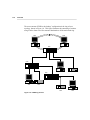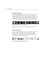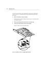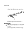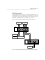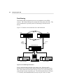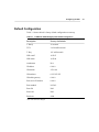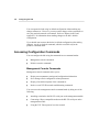
1
LinkBuilder® FDDI Workgroup Hub
User Guide
A member of the LinkBuilder FDDI family
For 3Com User Group Information
1-800-NET-3Com
or your local 3Com office
Manual Part No. 09-0447-000
Published July 1993. Printed in the U.S.A.
i
3Com Corporation
5400 Bayfront Plaza
Santa Clara
California, USA
95052-8145
© 3Com Corporation, 1993. All rights reserved. No part of this manual may be reproduced in any form or by
any means or used to make any derivative work (such as translation, transformation, or adaptation) without
permission from 3Com Corporation.
3Com Corporation reserves the right to revise this publication and to make changes in content from time to
time without obligation on the part of 3Com Corporation to provide notification of such revision or change.
3Com Corporation provides this guide without warranty of any kind, either implied or expressed, including,
but not limited to, the implied warranties of merchantability and fitness for a particular purpose. 3Com may
make improvements or changes in the product(s) and/or the program(s) described in this manual at any time.
If you are a government agency, then this software and documentation is provided to you subject to the
following restricted rights:
For units of the Department of Defense:
Restricted Rights Legend: Use, duplication, or disclosure by the Government is subject to restrictions as
set forth in subparagraph (c) (1) (ii) of the Rights in Technical Data and Computer Software Clause at 48
C.F.R. 52.227-7013. 3Com Corporation, 5400 Bayfront Plaza, Santa Clara, California 95052-8145.
For civilian agencies:
Restricted Rights Legend: Use, reproduction, or disclosure is subject to restrictions set forth in
subparagraph (a) through (d) of the Commercial Computer Software – Restricted Rights clause at 48
C.F.R. 52.227-19 and the limitations set forth in 3Com’s standard commercial agreement for the Software.
Unpublished rights reserved under the copyright laws of the United States.
Portions of this manual are reproduced in whole or in part with permission from (as appropriate).
3Com and LinkBuilder are registered trademarks of 3Com Corporation. CardFacts, NetFacts, Ask3Com,
3ComFacts, and CardBoard are service marks of 3Com Corporation.
Motorola is a registered trademark of Motorola Corporation. National Semiconductor is a registered
trademark of National Semiconductor Corporation. CompuServe is a service mark of CompuServe,
Incorporated.
Manual written by John Jeter. Edited by Nancy Kurahashi. Technical illustrations and production by Tim
Buckreus.
ii
LIMITED WARRANTY
HARDWARE: 3Com warrants its hardware products to be free from defects in workmanship and materials,
under normal use and service, for the following lengths of time from the date of purchase from 3Com or its
Authorized Reseller:
Bridge, gateway, and other internetworking products
Server products
Station products
Network adapters
LinkBuilder® 10BT and 10BTi hubs
Other transmission products
Spare parts and spares kits
Instrumentation
One year
One year
One year
Lifetime
Three years
One year
90 days
90 days
If a product does not operate as warranted during the applicable warranty period, 3Com shall, at its expense,
correct any such defect by repairing the defective product or part or, at its option, by delivering to Customer
an equivalent product or part to replace the defective item. All products that are replaced will become the
property of 3Com. Replacement products may be new or reconditioned. Any replaced or repaired product or
part has a ninety (90) day warranty or the remainder of the initial warranty period, whichever is longer.
3Com shall not be responsible for any software, firmware, information, or memory data of Customer
contained in, stored on, or integrated with any products returned to 3Com pursuant to any warranty.
SOFTWARE: 3Com warrants that the software programs licensed from it will perform in substantial
conformance to the program specifications therefor for a period of ninety (90) days from the date of purchase
from 3Com or its Authorized Reseller. 3Com warrants the magnetic media containing software against failure
during the warranty period. No updates are provided. 3Com’s sole obligation hereunder shall be (at 3Com’s
discretion) to refund the purchase price paid by Customer for any defective software products, or to replace
any defective media with software which substantially conforms to 3Com’s applicable published
specifications. Customer assumes responsibility for the selection of the appropriate applications program and
associated reference materials. 3Com makes no warranty that its software products will work in combination
with any hardware or applications software products provided by third parties, that the operation of the
software products will be uninterrupted or error free, or that all defects in the software products will be
corrected. For any third party products listed in the 3Com software product documentation or specifications
as being compatible, 3Com will make reasonable efforts to provide compatibility, except where the noncompatibility is caused by a “bug” or defect in the third party’s product.
STANDARD WARRANTY SERVICE: Standard warranty service for hardware products may be obtained
by delivering the defective product, accompanied by a copy of the dated proof of purchase, to 3Com’s
Corporate Service Center or to an Authorized 3Com Service Center during the applicable warranty period.
Standard warranty service for software products may be obtained by telephoning 3Com’s Corporate Service
Center or an Authorized 3Com Service Center, within the warranty period. Products returned to 3Com’s
Corporate Service Center must be pre-authorized by 3Com with a Return Material Authorization (RMA)
number marked on the outside of the package, and sent prepaid, insured, and packaged appropriately for safe
shipment. The repaired or replaced item will be shipped to Customer, at 3Com’s expense, not later than thirty
(30) days after receipt by 3Com.
iii
WARRANTIES EXCLUSIVE: IF A 3COM PRODUCT DOES NOT OPERATE AS WARRANTED
ABOVE, CUSTOMER’S SOLE REMEDY SHALL BE REPAIR, REPLACEMENT, OR REFUND OF THE
PURCHASE PRICE PAID, AT 3COM’S OPTION. THE FOREGOING WARRANTIES AND REMEDIES
ARE EXCLUSIVE AND ARE IN LIEU OF ALL OTHER WARRANTIES, EXPRESS OR IMPLIED,
EITHER IN FACT OR BY OPERATION OF LAW, STATUTORY OR OTHERWISE, INCLUDING
WARRANTIES OF MERCHANTABILITY AND FITNESS FOR A PARTICULAR PURPOSE. 3COM
NEITHER ASSUMES NOR AUTHORIZES ANY OTHER PERSON TO ASSUME FOR IT ANY OTHER
LIABILITY IN CONNECTION WITH THE SALE, INSTALLATION, MAINTENANCE OR USE OF ITS
PRODUCTS.
3COM SHALL NOT BE LIABLE UNDER THIS WARRANTY IF ITS TESTING AND EXAMINATION
DISCLOSE THAT THE ALLEGED DEFECT IN THE PRODUCT DOES NOT EXIST OR WAS CAUSED
BY CUSTOMER’S OR ANY THIRD PERSON’S MISUSE, NEGLECT, IMPROPER INSTALLATION OR
TESTING, UNAUTHORIZED ATTEMPTS TO REPAIR, OR ANY OTHER CAUSE BEYOND THE
RANGE OF THE INTENDED USE, OR BY ACCIDENT, FIRE, LIGHTNING, OR OTHER HAZARD.
LIMITATION OF LIABILITY. IN NO EVENT, WHETHER BASED IN CONTRACT OR TORT
(INCLUDING NEGLIGENCE) SHALL 3COM BE LIABLE FOR INCIDENTAL, CONSEQUENTIAL,
INDIRECT, SPECIAL, OR PUNITIVE DAMAGES OF ANY KIND, OR FOR LOSS OF REVENUE, LOSS
OF BUSINESS, OR OTHER FINANCIAL LOSS ARISING OUT OF OR IN CONNECTION WITH THE
SALE, INSTALLATION, MAINTENANCE, USE, PERFORMANCE, FAILURE, OR INTERRUPTION OF
ITS PRODUCTS, EVEN IF 3COM OR ITS AUTHORIZED RESELLER HAS BEEN ADVISED OF THE
POSSIBILITY OF SUCH DAMAGES.
Some states do not allow the exclusion of implied warranties or the limitation of incidental or consequential
damages for consumer products, so the above limitations and exclusions may not apply to you. This warranty
gives you specific legal rights which may vary from state to state.
3Com Corporation
5400 Bayfront Plaza
Santa Clara, CA 95052-8145
(408) 764-5000
6/15/92
iv
WARNING: This equipment (3C781, 3C782, 3C783) has been tested and found to comply with the limits for a
Class B digital device, pursuant to Part 15 of the FCC Rules. These limits are designed to provide reasonable
protection against harmful interference in a residential installation. This equipment generates, uses and can
radiate radio frequency energy and, if not installed and used in accordance with the instructions, may cause
harmful interference to radio communications. However, there is no guarantee that interference will not occur
in a particular installation. If this equipment does cause harmful interference to radio or television reception,
which can be determined by turning the equipment off and on, the user is encouraged to try to correct the
interference by one or more of the following measures:
■
Reorient or relocate the receiving antenna.
■
Increase the separation between the equipment and receiver.
■
Connect the equipment into an outlet on a circuit different from the one which the receiver is connected to.
■
Consult the dealer or an experienced radio/TV technician for help.
The user may find the following booklet prepared by the Federal Communications Commission helpful:
The Interference Handbook
This booklet is available from the U.S. Government Printing Office, Washington, D.C. 20402. Stock No.
004-000-00345-4.
NOTE: In order to maintain compliance with the limits of a Class B digital device, 3Com requires that you use
quality interface cables when connecting to this device. Changes or modifications not expressly approved by
3Com could void the user’s authority to operate this equipment. Suggested cable types are:
■
Thin Ethernet (50 ohm) for BNC connections: 3C530-xxx or equivalent
■
Thick Ethernet (50 ohm) for AUI connections: 3C120-xxx or equivalent
■
For UTP and STP connections:
Unshielded twisted-pair (100 ohm):
–
Level 3 LAN and high speed data cable. Example, Anixter® CM-00424BAG-3 or equivalent.
–
Level 4 extended distance LAN cable. Example, Anixter® CM-00424BAG-4 or equivalent.
Shielded twisted-pair (100 ohm):
–
Level 5 data grade media cable. Example, AT&T® type 2061, 1061, or equivalent.
Shielded twisted-pair (150 ohm):
–
Suggested cable type IBM® type 1, specification no. 4716748, type CL2, CM or MP, or equivalent.
WARNING: This equipment (3C784) has been tested and found to comply with the limits for a Class A digital
device, pursuant to Part 15 of the FCC Rules. These limits are designed to provide reasonable protection
against harmful interference in a commercial installation. This equipment generates, uses and can radiate radio
frequency energy and, if not installed and used in accordance with the instructions, may cause harmful
interference to radio communications. Operation of this equipment in a residential area is likely to cause
harmful interference, in which case, the user will be required to correct the interference at the user’s own
expense.
Changes or modifications not expressly approved by 3Com could void the user’s authority to operate this
equipment.
v
VDE Class B Compliance
Hiermit wird bescheinigt, dass die 3C781, 3C782, 3C783 in Übereinstimmung mit den Bestimmungen der Vfg
1046/1984 funk-entstört sind.
Der Deutschen Bundespost wurde das Inverkehrbringen dieses Gërates angezeigt und die Berechtigung zur
Überprüfung der Serie auf Einhaltung der Bestimmungen eingeräumt.
We hereby certify that the 3C781, 3C782, 3C783 comply with the RFI Suppression Requirements of Vfg
1046/1984. The German Postal Service was notified that the equipment is being marketed. The German
Postal Service has the right to re-test the equipment and to verify that it complies.
3Com Corporation
5400 Bayfront Plaza
Santa Clara, California, U.S.A.
95052-8145
vi
Contents
Quick Start
Road Map to Hub Operations
Unpacking the Hub 2
Unpacking the Modules 3
Installing the Modules 4
Connecting to the Ring 6
1
Chapter 1 Overview
FDDI Technology 1-2
Physical Medium Dependent (PMD) Protocol
Fiber-Optic 1-4
Shielded Twisted Pair (STP) 1-4
Unshielded Twisted Pair (UTP) 1-5
Physical (PHY) Protocol 1-5
Media Access Control (MAC) Protocol 1-5
Station Management (SMT) Protocol 1-6
Features and Functions 1-6
Site Selection 1-8
Typical FDDI Ring Setups 1-9
Management and Media Modules 1-11
Management Module 1-11
Media Modules 1-12
Fiber Media Port Module 1-12
STP Media Port Module 1-14
UTP Media Port Module 1-14
1-4
vii
Chapter 2 Installing the Hub
Unpacking the Hub 2-1
Mounting the Hub in a Rack 2-2
Equipping the Hub 2-5
Basic Contents 2-5
Hub Chassis 2-6
Media Port Modules 2-6
Installing the Battery 2-7
Keys for Fiber Port Modules 2-9
STP Cascade Connector 2-11
Installing Modules 2-12
Removing Modules 2-14
Accessing the Hub 2-16
Changing the Serial Port’s Baud Rate 2-16
Installing an Optional Modem 2-18
Using Telnet to Access the Hub 2-19
Planning Connections 2-19
FDDI Cabling Rules 2-20
Fiber-Optic Cable 2-20
Shielded Twisted-Pair Cable 2-20
Unshielded Twisted-Pair Cable 2-21
Data Flow Specifications 2-23
Connecting to the Dual Ring 2-24
Installing an Optical Bypass Switch 2-26
Chapter 3 Configuring the Hub
Attachment Options 3-1
Dual Attachment Hub 3-2
Single Attachment Hub 3-4
Null Attachment Hub 3-5
Dual Homing 3-6
Default Configuration 3-7
Accessing Configuration Commands 3-8
Management Console Commands 3-8
Primitive Console Commands 3-9
Accessing the Primitive Console Command Mode 3-9
Returning to the Management Console Command Mode
viii
3-11
Port Connections 3-11
Configuring Modules 3-15
Using the STP Cascade Connector
3-18
Chapter 4 Setting Up the Hub
Commands 4-1
Command Descriptions 4-2
Display of Command Results 4-2
Setting Addresses 4-3
IP Address 4-3
Netmask 4-4
Broadcast Address 4-4
Default Gateway Address 4-4
Setting the Password 4-5
Setting Attachment Port Configurations 4-6
Using Station Management Parameters 4-7
Setting SMT Parameters 4-7
Neighbor Notification Timer (T-Notify) 4-7
Target Token Rotation Time (T-Req) 4-8
Link Error Rate (LER) 4-8
Displaying SMT Parameters 4-11
Maximum Token Rotation Time (T-Max) 4-11
Negotiated Time (T-Neg) 4-11
Valid Transmission Timer (TVX) 4-11
Downloading New Images 4-12
Downloading from the TFTP Option 4-12
Displaying the Current Download Method 4-14
ix
Chapter 5 Using the Hub
Getting Hub Information 5-1
Show Hub Configuration 5-1
Show MAC Frame Statistics 5-1
Show IP Addresses 5-3
Show MIB Counters 5-3
Show Neighbor Stations 5-4
Show Station Identification 5-4
Show Ports Information 5-5
Module Designation 5-6
PMD Class 5-6
PHY Type 5-7
Neighbor 5-7
PCM State 5-7
Connect State 5-9
LER Alarm and LER Cutoff 5-9
LER Estimate 5-9
LEM Rejects 5-10
LEM Count 5-10
Show Ring State 5-10
Interpreting the LEDs 5-11
Management Module LEDs 5-11
WRAP LED 5-13
FAN FAIL LED 5-14
HI TEMP LED 5-14
LOW BATT LED 5-14
Dangerous Environmental Conditions Display
RESET Function 5-15
Media Module LEDs 5-16
Using Miscellaneous Commands 5-17
Diagnosing Network Problems 5-17
ping Command 5-18
route Command 5-19
arp Command 5-20
show log and clear log Commands 5-21
Using Connectivity Commands 5-22
connect and disconnect Commands 5-22
logout Command 5-22
x
5-14
Appendix A System Messages
Error Messages A-1
Download Messages A-4
Fault Log Error Code Messages A-6
Appendix B Technical Specifications
Appendix C Commands
Management Console Commands C-1
Set Commands C-1
set attach C-1
set baud C-2
set boot C-3
set gateway C-4
set help C-4
set ip C-4
set ler C-5
set pwd C-6
set tnotify C-6
set treq C-6
Show Commands C-7
show attach C-7
show baud C-7
show boot C-7
show cfm C-8
show fstats C-9
show gateway C-9
show help C-10
show ip C-10
show log C-10
show mib counters C-10
show neigh C-11
show obs C-11
show ports C-12
show rev C-13
show ring C-14
xi
show sid C-14
show tmax C-14
show tneg C-15
show tnotify C-15
show treq C-15
show tvx C-15
Diagnostic and Connectivity Commands
arp C-16
clear C-16
connect C-17
disconnect C-17
help C-17
logout C-17
ping C-18
reset C-18
route C-18
Primitive Console Commands C-19
Set Commands C-20
set attach C-20
set baud C-20
set boot C-20
set defaults C-20
set gateway C-20
set help | ? C-20
set ip C-20
set pwd C-20
set tnotify C-20
set treq C-21
xii
C-16
Display Commands C-21
show attach C-21
show baud C-21
show boot C-21
show gateway C-21
show help | ? C-21
show ip C-21
show log C-21
show obs C-22
show rev C-22
show sid C-22
show tnotify C-22
show treq C-22
show tvx C-22
Miscellaneous Commands C-22
clear C-22
help | ? C-22
reset C-22
Appendix D Technical Support
On-line Product Support D-1
CardBoard Bulletin Board Service D-1
Automated Fax Service D-2
Ask3Com On-line Service D-2
3Com Documentation on CD-ROM D-3
Support from Your Network Supplier D-3
U.S. and Canada D-3
Outside the U.S. and Canada D-3
Returning Products for Repair D-5
Glossary
Index
xiii
Figures
xiv
1-1.
1-2.
1-3.
1-4.
1-5.
1-6.
1-7.
1-8.
1-9.
Ring Wrap 1-3
The LinkBuilder FDDI Workgroup Hub 1-8
Physical Topology for Typical FDDI Ring 1-9
FDDI Ring of Trees 1-10
Management Module, Front Panel 1-11
Fiber Media Port Module, Front Panel 1-13
Removing a Dust Plug from a Fiber Transceiver 1-13
STP Media Port Module, Front Panel 1-14
UTP Media Port Module, Front Panel 1-14
2-1.
2-2.
2-3.
2-4.
2-5.
2-6.
2-7.
2-8.
2-9.
2-10.
2-11.
2-12.
Attaching Mounting Brackets to the Hub 2-3
LinkBuilder FDDI Workgroup Hub Installed in a Distribution Rack 2-4
Battery Location on the Management Module 2-8
Media Module Keys Identified by Port Type 2-9
Inserting a Type M Key into a Fiber Transceiver 2-10
STP Module Cascade Connector 2-12
Cross-over Connections on a UTP Cable 2-21
UTP Cabling Distances per ANSI Standards 2-22
Direction of Data Flow Through a Hub and Stations 2-24
Optical Bypass Switch 2-26
Cabling for Installing an Optical Bypass Switch 2-27
Rack Mounting a Hub with an Attached Optical Bypass Switch 2-28
3-1.
3-2.
3-3.
3-4.
3-5.
3-6.
3-7.
5-1.
5-2.
5-3.
5-4.
5-5.
5-6.
5-7.
5-8.
5-9.
Dual Attachment Hub (DAC) 3-2
Dual Attachment Hubs (DACs) in Wrap State 3-3
Single Attachment Hub (SAC) 3-4
Null Attachment Hub (NAC) and Connected Stations
(SAS and DAS) 3-5
Dual Homing Connections 3-6
Upstream and Downstream Neighbors 3-13
Using Two STP Cascade Connectors to Allow a Dual Attachment
Configuration 3-18
Display of Attachment Port Configuration 5-1
Display of MAC Frame Statistics 5-2
Display Produced by show IP Command 5-3
Display Produced by show MIB counters Command 5-3
Display of Neighbors’ Addresses 5-4
Display of Station Identifier 5-4
Example of show ports Command Information 5-5
Display of a MAC’s Ring Management State 5-10
LEDs on the STP Module 5-16
xv
Tables
xvi
2-1.
2-2.
2-3.
DB-9 STP Connector Pin Assignments 2-21
RJ-45 UTP Connector Pin Assignments 2-22
FDDI Port Types 2-23
3-1.
3-2.
3-3.
3-4.
3-5.
LinkBuilder FDDI Workgroup Hub Default Configuration 3-7
Selecting Port Configurations for Attachment Types 3-12
Port Connection Rules 3-14
Definitions for the Port Connection Rules 3-15
Configuring Modules 3-16
4-1.
Definition of Boot Methods
5-1.
5-2.
5-3.
5-4.
5-5.
5-6.
5-7.
5-8.
5-9.
5-10.
Components Polled by the show fstats Command 5-2
Definition of MIB Counters 5-4
Port Media Types 5-6
Physical Layer Port Types 5-7
Physical Connection Management States 5-8
Connect States 5-9
Ring Management States 5-11
Interpreting Management Module LEDs 5-12
CFM State Values Displayed by the show cfm Command
Interpreting Media Module LEDs 5-17
4-15
5-13
®
3Com’s FDDI Training and
Reference Manual
Understanding FDDI (3CS-360) is a pragmatic independent study course and
reference manual written for professionals involved in the design,
implementation, or support of multivendor FDDI networks.
Chapters 1 through 5 contain core information about FDDI. These chapters
explore critical elements of an FDDI environment, including attachment
stations, MAC interfaces, concentrators, and optical bypass switches. Port
keying and configuration, internetworking, ring startup, operation, fault
isolation and ring recovery, light properties, fiber media, and optics are also
covered.
Chapters 6 through 12 constitute a 250-page technical reference that takes
you down to the engineering level. Here 3Com interprets the FDDI standards
to provide tangible and accessible information on all four FDDI protocol
layers and the SMT Management Information Base.
®
®
LinkBuilder
FDDI WORKGROUP HUB
®
3
UTP PORT MODULE
GRN = SIGNAL DETECT
GRN = PORT STATE
YEL = LINK ERROR
STP PORT MODULE
PWR
®
1
GRN = SIGNAL DETECT
GRN = PORT STATE
YEL = LINK ERROR
FIBER PORT MODULE
PWR
®
0
GRN = SIGNAL DETECT
GRN = PORT STATE
YEL = LINK ERROR
PWR
®
2
GRN = SIGNAL DETECT
GRN = PORT STATE
YEL = LINK ERROR
PWR
RESET
OPTICAL
BYPASS
SERIAL PORT
MANAGEMENT MODULE
ATTACH
B/A
S/M
STATUS
TOKEN
WRAP
FAN
FAIL
HI
TEMP
LOW
BATT
M/M
This text-based course comes with a testing diskette to guide and reinforce
the learning process. Students who pass the test receive a certificate of
completion.
For ordering information and details about other courses in 3Com’s data
networking technology series, turn the page.
®
Additional 3Com Data
Networking Courses
3Com’s practical self-paced training on the networking industry’s prevailing
standards and architectures provides a cost-effective way for professionals
to keep pace with the complex planning and support demands of a multivendor
data network. Each course contains supplementary technical materials
organized for easy future reference.
These courses come in text format, with an interactive testing diskette to
guide and reinforce the learning process. Students who pass the final test
receive a certificate of completion.
Introduction to Bridging and Routing (3CS-011)
Network Architectures, Standards and Protocols (3CS-330)
Introduction to SNMP (3CS-350)
®
®
LinkBuilder
FDDI WORKGROUP HUB
®
3
®
2
GRN = SIGNAL DETECT
GRN = PORT STATE
YEL = LINK ERROR
UTP PORT MODULE
PWR
GRN = SIGNAL DETECT
GRN = PORT STATE
YEL = LINK ERROR
STP PORT MODULE
PWR
®
1
GRN = SIGNAL DETECT
GRN = PORT STATE
YEL = LINK ERROR
GRN = SIGNAL DETECT
GRN = PORT STATE
YEL = LINK ERROR
Understanding TCP/IP (3CS-340A)
®
0
FIBER PORT MODULE
PWR
PWR
RESET
OPTICAL
BYPASS
SERIAL PORT
MANAGEMENT MODULE
ATTACH
B/A
S/M
STATUS
TOKEN
WRAP
FAN
FAIL
HI
TEMP
LOW
BATT
M/M
WAN Technologies for Internetworking (3CS-370)
Order through your authorized 3Com reseller or local 3Com office. Availability
in self-study format may vary outside the U.S. To order directly from 3Com
Education Services, call 1-800-876-3266, press option 7, then option 3. Callers
outside the U.S. should call 408-492-1790 or contact the 3Com office in their
area for local pricing and delivery.
Chapter Title
®
wants to hear from you!
To ensure the very best 3Com service and
support, take advantage of our One-Year
Warranty on 3Com‘s LinkBuilder® FDDI
Workgroup Hub.
Please fill out and return the enclosed
registration card to start your one-year
warranty period.
1-1
1-2
Chapter Title
Customers in the countries shown below should send the completed
registration card to the appropriate address.
■
France, Spain, Portugal, Greece
3Com France, Marketing Department
ZA de Courtaboeuf
25, Ave de la Baltique
B.P. 609
91945 Les Ulis Cedex
France
■
Italy
3Com Mediterraneo Srl, Marketing Department
Via Michelangelo Buonarroti 1
20093 Cologno Monzese (MI)
Milano
Italia
■
United Kingdom, Eire
3Com UK Ltd., Marketing Department
Pacific House
Third Avenue, Globe Park
Marlow-on-Thames
Buckinghamshire, SL7 1YW
United Kingdom
■
Sweden, Finland, Norway, Denmark
3Com Nordic AB, Marketing Department
Box 1110
164 22 Kista
Sweden
■
Germany, Austria, Switzerland
3Com GmbH, Marketing Department
Gustav-Heinemann-Ring 123
8000 Muenchen 83
Germany
■
Belgium, Netherlands, Luxembourg
3Com Benelux, Marketing Department
Planetenweg 80
2nd Floor
2132 HP Hoofddorp
Netherlands
Customers in other non-U.S. locations should send the registration card
to the U.S. address on the front of the card.
Quick Start
1
Quick Start
Use this Quick Start procedure if:
■
You are experienced in installing and operating LinkBuilder FDDI hubs.
■
You have an FDDI segment running with other network devices attached
to it.
Road Map to Hub Operations
The steps listed below summarize the procedures needed to make the 3Com®
LinkBuilder® FDDI Workgroup Hub operational. The list also shows where
each step is discussed in this user guide.
1.
Unpacking the hub and modules
– Quick Start
– Chapter 2: “Unpacking the Hub”; “Installing Modules”
2.
Installing the modules
– Quick Start
– Chapter 2: “Installing Modules”
3.
Connecting a terminal
– Chapter 2: “Accessing the Hub”
4.
Determining legal port connections
– Chapter 2: “Planning Connections”
– Chapter 3: “Attachment Options”; “Port Connections”
5.
Attaching the hub to the ring
– Chapter 2: “Connecting to the Dual Ring”
6.
Attaching other devices to the hub
– Chapter 2: “Data Flow Specifications”
2
Quick Start
7.
Configuring attachment ports
–
Chapter 3: “Configuring Modules”
8.
Setting up the hub for network operations
–
Chapter 4: “Setting Addresses”;
“Using Station Management Parameters”;
“Downloading New Images”
9.
Monitoring hub operations
–
Chapter 5: “Getting Hub Information”;
“Interpreting the LEDs”;
“Using Miscellaneous Commands”
Unpacking the Hub
The FDDI Workgroup Hub is shipped separately from the management module
and media port modules. To unpack the hub, follow these steps:
1.
Open the shipping container and carefully remove its contents.
2.
Return all packing materials to the shipping container and save it.
If the hub must be returned, ship it in its original shipping container (or
equivalent), or the warranty will be voided.
3.
Verify that you have received all items on the packing list, and inspect
each item for damage.
The basic package includes the following items:
■
LinkBuilder FDDI Workgroup Hub (base unit)
■
LinkBuilder FDDI Workgroup Hub User Guide
■
LinkBuilder FDDI System Software diskette, version 1.0
■
Standard ac power cord
■
Two brackets and eight screws for rack mounting
■
Four rubber pads for tabletop placement
Quick Start
3
The LinkBuilder FDDI System Software diskette, version 1.0, contains a
readme file and a backup image for the flash EPROM.
A 3-volt lithium battery is shipped with the management module. The
battery is in a small bag inside the management module shipping container.
If you ordered an STP media port module, one cascade connector will be
shipped with the module.
For complete instructions on installing the hub, the modules, and the
battery, see Chapter 2, “Installing the Hub.”
4.
Place the hub either in an EIA 19-inch rack or on a table or desk.
■
For rack mounting, attach the two brackets to the front sides of the
hub. Then attach the brackets to the front mounting rails of the rack.
Use the eight screws that are supplied with the hub. (See Figures 2-1
and 2-2.)
■
For tabletop placement, fasten the rubber pads that come with the hub
on the four bottom corners of the base unit.
Unpacking the Modules
The management modules and media port modules are packaged and shipped
separately. Two modules (the management module and at least one media port
module) plus the hub constitute the minimum functional setup. To unpack the
modules, follow the steps below:
CAUTION: Each module is packed in an antistatic bag to protect it during
shipment. To avoid damaging any highly static-sensitive components on the
module or the hub, be sure to reduce any static electricity on your person. One
way to do this is to touch the metal part of the hub. You can maintain
grounding by wearing a wrist strap attached to the hub.
1.
Carefully remove each module from its shipping container and set it
aside.
4
Quick Start
2.
Keep all packing and shipping materials.
If a module must be returned, ship it in its original shipping container (or
one providing equivalent protection), or the warranty will be voided.
3.
One at a time, remove each module from its antistatic bag.
4.
Check the modules for any visible signs of damage.
If you detect damage, immediately notify your network supplier and the
carrier that delivered the module.
5.
Place the modules back in their antistatic bags until you are ready to
install them.
Installing the Modules
NOTE: You must install the management module first. It can only be installed
in slot 0. It will not function in any other slot. Install the remaining modules in
adjacent slots (in numerically ascending order) so there are no empty slots
between modules.
When you install the management module for the first time, be sure that power
to the hub is off. There is no power switch on the hub. Power to the hub is
provided by connecting the power cord to the hub and to an ac outlet.
NOTE: The hub allows “power-on insertion,” which means that you do not
have to unplug the power cord for module insertion or removal. After removing
or inserting a module, press the RESET button, which is recessed on the
management module, or enter the reset command on the command line. This
reinitializes the ring and causes the system to run its power-on self-tests (POST).
Quick Start
5
To install the modules, follow these steps:
1.
Remove all jewelry from your hands and wrists.
2.
If necessary, remove blanking plates from the module slots.
Keep the removed blanking plates in a safe place for possible future use.
3.
Remove the module from its antistatic bag.
Prepare a clean, level work area nearby on which to place the module.
Avoid contact with any of the module’s components.
4.
Insert the module slowly into its slot.
5.
Gently align and push the module’s bus connector into its slot in the
backplane of the hub.
6.
When the module is completely seated, tighten the captive thumb
screws on each end of the module.
7.
To turn on the hub, plug one end of the ac power cord into the back of
the hub and the other end into an electrical socket.
The green PWR LED lights, indicating the hub is on and ready for
configuration.
After installing the management module and one or more media modules, one or
two empty slots may remain in the base unit. Insert a blanking plate into each of
these empty slots. This keeps objects from falling into the hub and prevents RF
emissions from an open slot.
6
Quick Start
Connecting to the Ring
After installing the modules and plugging in the power cord, you are ready to
connect the hub to the ring by attaching the appropriate cables to the attachment
ports, which are the two leftmost ports on the module installed in slot 1. To
complete the connection to the ring, you must configure the attachment ports.
For detailed information on connecting the hub to the ring, see the references in
the “Road Map to Hub Operations” section earlier in this chapter.
Overview
1-1
Chapter 1
Overview
The 3Com® LinkBuilder® FDDI Workgroup Hub brings Fiber Distributed Data
Interface (FDDI) high-speed LAN technology to the desktop. (Throughout this
guide, the LinkBuilder FDDI Workgroup Hub will be referred to as “the hub.”)
The hub supports remote management via Station Management (SMT) 7.3 or
Telnet protocol. Local management is provided via a console interface or a
modem attached to the management module’s serial port. The SMT 7.3
standard specifies the format of management information so that it is consistent
with the object-oriented approach defined by OSI management standards. The
standard SMT Management Information Base (MIB) variables are present in the
LinkBuilder FDDI Workgroup Hub software.
A modular stand-alone device, the hub provides four module slots and a passive
backplane. When installed and equipped with the appropriate modules, the hub
can be connected to the FDDI backbone ring, to other FDDI hubs, and to other
stations. The RS-232–based console interface provides the capability to
configure and monitor the media port modules installed in the chassis.
The hub chassis contains an integrated internal power supply and a fan. It
requires a single management module and supports one to three media modules
for ring and station attachment.
The hub is an intelligent device with a unique FDDI MAC (Media Access
Control) address implemented with National Semiconductor® Corporation’s
BMAC (FDDI Media Access Controller) technologies. In addition, National’s
BSI (FDDI System Interface) implements an interface between the BMAC
device and the host system, providing a multiframe, MAC-level interface to one
or more MAC users. The hub’s single MAC supports dual, single, or null
attachment and dual homing.
1-2
Overview
The management module is based on the Motorola® 68EC020 processor, which
provides the following:
■
256 KB of nonvolatile RAM
■
1 MB of local RAM
■
512 KB of EPROM
■
1 MB of flash memory
■
128 KB of RAM for frame buffer and descriptors
This guide is intended for network installers and operators who are familiar with
FDDI technology and experienced in installing hubs. The next section contains
a brief summary of FDDI technology; it is intended as an overview only. (For
detailed information about FDDI architecture and its functionality, 3Com
recommends that you secure the FDDI self-paced study course, Understanding
FDDI, 3CS-360, available through 3Com Education Services.)
FDDI Technology
FDDI technology is an American National Standards Institute (ANSI) standard
that supports data transfer rates of 100 million bits per second (100 Mbps).
Advancements in fiber technology allow modulated beams of light to be carried
in dual counter-rotating token rings made of glass fiber-optic cable. The FDDI
standard now includes the definition of other types of cabling media, including
shielded twisted pair (STP) and unshielded twisted pair (UTP). FDDI provides
for up to 500 nodes operating over tens of kilometers. The maximum network
length is 100 km.
FDDI’s dual-ring architecture provides a high level of reliability and fault
tolerance. Under normal operation one of the rings, called the primary ring or
the trunk ring, carries data traffic. The other ring, called the secondary ring, is
generally used for automatic recovery in the event of a break in the primary
ring. If a fault occurs, as shown in Figure 1-1, the dual attached stations on
either side of the fault detect and automatically bypass it. This ring
reconfiguration is known as a ring wrap.
Overview
1-3
Break in ring or station failure
Ring wrap
Ring wrap
Primary ring
Secondary ring
Figure 1-1. Ring Wrap
The FDDI standard developed by the American National Standards Institute
(ANSI) defines four protocols:
■
Physical Medium Dependent (PMD)
■
Physical (PHY)
■
Media Access Control (MAC)
■
Station Management (SMT)
Each of these protocols is briefly defined below.
1-4
Overview
Physical Medium Dependent (PMD) Protocol
The Physical Medium Dependent protocol provides all of the services necessary
to exchange data across the cable medium. PMD also specifies an optional
optical bypass facility that enhances reliability. This bypass capability is
invoked when an FDDI station is powered off. (For information on the optical
bypass switch, see Chapter 2, “Installing the Hub.”)
The PMD services included for each type of media supported by the
LinkBuilder FDDI Workgroup Hub are listed below.
Fiber-Optic
The PMD standard provides these services for fiber media:
■
Optical power and cable requirements for 62.5/125 µm fiber-optic cables
■
Power requirements for optical bypass switches and fiber-optic transceivers
■
FDDI cable connector (the Media Interface Connector [MIC]), mating
requirements, and keying
■
Light wavelength of 1300 nm (nanometers)
Shielded Twisted Pair (STP)
The PMD standard uses the SDDI de facto standard and provides these services
for STP:
■
Transmit signal amplitude of 350–700 mV, peak-to-peak
■
Cable fault detect
■
DB-9 cable connector, specifying M as a male connector and A, B, and S
as female connectors
Overview
1-5
Unshielded Twisted Pair (UTP)
The ANSI TP-PMD standard provides these services for UTP:
■
Cable requirements for category 5 UTP as defined by EIA/TIA-568
■
Electrical requirements for UTP transceivers
■
FDDI-UTP cable connector
Physical (PHY) Protocol
The Physical protocol is responsible for encoding and decoding of data and
control information on the FDDI network. It specifies the following:
■
4B/5B nonreturn to zero inverted (NRZI) encoding scheme (for fiber and
STP modules)
■
MLT-3 with stream cipher encoding scheme (for UTP modules)
■
Clocking rules
■
Clocking frequency of 125 MHz
■
Serial-to-parallel conversion rules
Media Access Control (MAC) Protocol
The Media Access Control protocol controls the flow of data on the FDDI ring.
The MAC typically exists in every hub and station accessed by the FDDI ring,
but stations without MACs are allowed. This protocol specifies the following:
■
Token-passing protocol
■
Capture and retransmission of token
■
Packet formation and framing of data
■
Address generation and recognition
■
32-bit cyclic redundancy check (CRC) verification and error detection
■
Recovery mechanisms
1-6
Overview
NOTE: In contrast to the PMD protocol, the PHY and MAC protocols are
media-independent; that is, the same protocols function regardless of the
medium being used (fiber, STP, or UTP).
Station Management (SMT) Protocol
The Station Management protocol is involved in network management and
monitoring for all layers of the FDDI stack. Every node on an FDDI ring
participates in the management of the ring. As such, all nodes exchange SMT
information to control network operation. SMT specifies the following:
■
Status of links between nodes
■
Error detection and fault isolation algorithms
■
Monitoring of all ring and station activities
■
Ring maintenance
■
Ring initialization, control, and performance
Features and Functions
The LinkBuilder FDDI Workgroup Hub performs the following tasks in an
FDDI network:
■
Connects end stations, bridges, routers, and other FDDI devices as well as
additional hubs to the network
■
Isolates segment breaks through an attachment configuration called dual
homing and dual attachment
■
Bypasses nodes that have been turned off or are experiencing problems
■
Extends the network’s geographical diameter by regenerating all received
signals when repeating them onto the network
Overview
1-7
The hub provides the following features:
■
Media flexibility. You can use any mix of one, two, or three of these port
modules in the hub:
–
FDDI media port module supporting 62.5/125 µm fiber-optic cable
per the ANSI FDDI standard
–
STP media port module supporting shielded twisted-pair (STP) type 1
cable and the SDDI de facto standard
–
UTP media port module supporting level 5 and screened level 5, data
grade unshielded twisted-pair (UTP) cabling system per the ANSI
TP-PMD standard
■
Upgradeability. You can easily change from copper media to fiber media
and vice versa using the available port modules.
■
Configurability. You can configure the two leftmost ports of the slot 1
module to meet any one of four network configurations: dual attachment,
single attachment, null attachment, and dual homing.
■
Serviceability with power-on insertion. You can insert and remove the
media port modules without removing power from the hub.
■
Flash EPROM. The presence of the flash EPROM makes the hub’s
software easily upgradeable because future software images can be
downloaded into flash memory over the network via the Trivial File
Transfer Protocol (TFTP). (See the section “Downloading New Images” in
Chapter 4 for information on downloading images into the flash EPROM.)
■
FDDI benefits. You can take advantage of the many benefits provided by
FDDI technology, including:
–
–
–
–
–
–
Increased data rate of 100 Mbps
Longer distance between nodes via fiber-optic cable
Immunity to electronic “noise” (fiber only)
Support of large networks comprising up to 500 nodes
Fault tolerance and fault isolation
Improved network management
1-8
Overview
Figure 1-2 shows the LinkBuilder FDDI hub with the management module and
all three types of media modules installed.
®
GRN = SIGNAL DETECT
GRN = PORT STATE
YEL = LINK ERROR
UTP PORT MODULE
PWR
®
GRN = SIGNAL DETECT
GRN = PORT STATE
YEL = LINK ERROR
STP PORT MODULE
PWR
®
GRN = SIGNAL DETECT
GRN = PORT STATE
YEL = LINK ERROR
FIBER PORT MODULE
PWR
®
®
GRN = SIGNAL DETECT
GRN = PORT STATE
YEL = LINK ERROR
PWR
OPTICAL
BYPASS
SERIAL PORT
RESET
MANAGEMENT MODULE
ATTACH
B/A
S/M
STATUS
TOKEN
WRAP
FAN
FAIL
HI
TEMP
LOW
BATT
M/M
Figure 1-2. The LinkBuilder FDDI Workgroup Hub
Site Selection
The hub is housed in a 16.8 x 11.6 x 5.2 inch chassis that can be placed on a
tabletop or easily mounted in an Electronics Industries Association (EIA)
standard 19-inch rack. You can mount more than one hub in a rack depending
on your network needs.
Included with the chassis are four small rubber pads (to be inserted on the
bottom four corners for tabletop placement) and two attachable brackets (to be
attached on two sides for rack mounting) for your choice of placement.
When selecting a site for the hub, remember that the hub can be connected to an
external terminal for initial configuration. In this case you will need room in
front of the chassis to place and access the terminal.
Instead of attaching a terminal to the hub, you can configure the hub over the
network by using the TCP Telnet protocol. You can also access the hub via a
modem attached to the serial port.
Overview
Typical FDDI Ring Setups
The hub can be used singly or in groups to bring FDDI to the desktop.
Figure 1-3 shows a typical ring setup, in which:
■
Two dual attachment stations (DAS) are connected to the trunk ring.
■
Two dual attachment hubs (DAC) are connected to the trunk ring.
■
Two single attachment stations (SAS) are connected to each of the hubs.
NOTE: 3Com uses the standard acronym DAC (for dual attachment
concentrator) shown above but calls the concentrator a hub rather than a
concentrator.
DAS 1
DAS 2
DAC 1
B
SAS 1
DAC 2
A
B
SAS 2
SAS 3
Figure 1-3. Physical Topology for Typical FDDI Ring
A
SAS 4
1-9
1-10
Overview
The most common “FDDI to the desktop” configuration is the ring of trees
topology, shown in Figure 1-4. This figure illustrates the connecting of stations
using a hub to form a tree-like structure that branches off the main trunk ring.
DAS
DAS
DAC
SAC
SAS
SAS
SAC
SAS
SAS
SAS
Figure 1-4. FDDI Ring of Trees
SAS
Overview
1-11
Management and Media Modules
The hub chassis provides slots for one management module (required) and three
media modules, which can be mixed or matched. This section briefly describes
each of these modules. (For information about the operation of the management
and media modules, see Chapter 5, “Using the Hub.”)
Management Module
The LinkBuilder FDDI Management Module, hereafter called the “management
module,” must be inserted in slot 0 (the bottom slot) of the hub. Its main
purpose is to run the Station Management (SMT) 7.3 software that is required
for FDDI operations.
The management module provides management and configuration functions
through a console interface. Access to this interface is either by a 9-pin
RS-232C console serial port for a terminal or modem connection or via a TCP
Telnet protocol connection over the network.
Figure 1-5 shows the front panel of the management module, which provides a
6-pin mini-DIN receptacle for the connection to an optical bypass switch (OBS).
®
GRN = SIGNAL DETECT
GRN = PORT STATE
YEL = LINK ERROR
PWR
OPTICAL
BYPASS
SERIAL PORT
RESET
MANAGEMENT MODULE
ATTACH
B/A
S/M
STATUS
TOKEN
WRAP
FAN
FAIL
HI
TEMP
LOW
BATT
M/M
Figure 1-5. Management Module, Front Panel
The management module contains a recessed RESET button for reinitializing
the hub’s software, running the power-on self-tests (POST), and running the
flash EPROM. You can also use the RESET button to access the primitive
console mode. (Refer to “Accessing Configuration Commands” in Chapter 3
for information on accessing the two console command modes.)
1-12
Overview
By interpreting the LEDs on the management module, you can:
■
Monitor network activity
■
Determine chassis environmental factors
■
Discover ring attachment configuration
Refer to “Interpreting the LEDs” in Chapter 5 for detailed information about the
LEDs on all hub modules.
Media Modules
Three media modules are currently available. Each module can be placed in any
slot, but the modules must be installed from the bottom up, beginning with slot 1.
Do not leave empty slots between modules.
The two leftmost ports on any module installed in slot 1 are designated as
attachment ports. The module in slot 1 is given a default configuration of dual
attachment, B/A connection. Only the two leftmost ports of modules installed in
slot 1 can be configured.
The three modules are:
■
LinkBuilder FDDI 4-port Optic Module (fiber media port module)
■
LinkBuilder FDDI 6-port STP Module (STP media port module)
■
LinkBuilder FDDI 8-port UTP Module (UTP media port module)
Fiber Media Port Module
The fiber media port module provides four ports, as shown in Figure 1-6. When
this module is installed in slot 1, you can configure the attachment ports (the two
leftmost ports) as B and A, S and M, or M and M as necessary to support a given
attachment. (Refer to Chapter 4 for instructions for configuring the attachment
ports.) The remaining two ports are M (master) ports by default.
Overview
®
GRN = SIGNAL DETECT
GRN = PORT STATE
YEL = LINK ERROR
1-13
FIBER PORT MODULE
PWR
Figure 1-6. Fiber Media Port Module, Front Panel
If you insert the module in slots 2 or 3, all ports are automatically configured as
M ports. With three fiber modules installed in the hub, 12 fiber MIC ports are
available.
The fiber media port module is shipped with dust plugs inserted in its
transceivers to protect the fiber-optic connectors from contamination. Keep a
dust plug in each port until you are ready to insert a fiber cable into the port.
Figure 1-7 shows how to remove a dust plug from a fiber transceiver.
Figure 1-7. Removing a Dust Plug from a Fiber Transceiver
1-14
Overview
STP Media Port Module
Figure 1-8 shows the front panel of the six-port STP media port module. All of
its ports are configured as M ports by default. You can specify any port
configuration for the attachment ports, but you must use a special connector
called the STP cascade connector to configure the leftmost attachment port as S.
To configure the attachment ports as B and A requires two cascade connectors.
Refer to Chapter 2 for additional information on the STP cascade connector.
®
GRN = SIGNAL DETECT
GRN = PORT STATE
YEL = LINK ERROR
STP PORT MODULE
PWR
Figure 1-8. STP Media Port Module, Front Panel
If you install an STP module in each of the three hub slots, 18 STP ports are
available.
UTP Media Port Module
Figure 1-9 shows the front panel of the UTP media port module, which provides
eight ports configured as M ports by default. You can specify any port
configuration (B/A, S/M, or M/M) for the attachment ports. No adapter or
special connector is needed for the UTP module. If you install three UTP
modules in the hub, 24 UTP ports are available.
®
GRN = SIGNAL DETECT
GRN = PORT STATE
YEL = LINK ERROR
PWR
Figure 1-9. UTP Media Port Module, Front Panel
UTP PORT MODULE
Installing the Hub
2-1
Chapter 2
Installing the Hub
This chapter describes installation of the LinkBuilder FDDI Workgroup Hub. It
includes the following topics:
■
Unpacking the hub
■
Rack mounting the hub
■
Equipping the hub
■
Installing and removing modules
■
Accessing the hub
■
Understanding data flow
■
Installing an optional optical bypass switch
NOTE: For a step-by-step procedure for installing the hub and preparing it for
network operations, see the Quick Start chapter at the beginning of this guide.
Unpacking the Hub
To unpack the hub, follow these steps:
1.
Open the shipping container and carefully remove its contents.
2.
Return all packing materials to the shipping container and save it.
If the hub must be returned, ship it in its original shipping container (or one
providing equivalent protection), or the warranty will be voided.
3.
Verify that you have received all items on the packing list, and inspect
each item for damage.
If you find any omissions or damage, contact your network supplier and
the carrier that delivered the package.
2-2
Installing the Hub
Mounting the Hub in a Rack
Mounting the hub in a rack involves installing mounting brackets onto the hub
and mounting the hub in the rack. To mount the hub in a 19-inch distribution
rack, follow these instructions:
1.
Lift the hub from its packing container and place it on a table or other
flat surface.
You should get help lifting the hub; it weighs slightly more than 15 pounds
(6.8 kg). You will also need help when screwing the hub into the rack.
2.
Determine where you will attach the hub to the rack.
Align the mounting brackets to the holes in the vertical rails of the rack and
mark the holes where you will screw the mounting brackets.
3.
Attach the two supplied mounting brackets to the hub, using the
screws that came with the hub. See Figure 2-1.
Locate the holes on each side of the hub into which you will attach the
mounting brackets.
If you lose one of the screws, replace it with a 10/32 x 3/8 inch pan-head
cross-recessed screw with an integral lock washer.
4.
With the help of at least one other person, carefully lift the hub into
position in the rack.
Align the mounting brackets to the holes you designated for mounting.
Installing the Hub
2-3
While holding the hub in place, insert the four mounting screws supplied
with the hub into the mounting holes in each bracket (two screws per
bracket).
5.
Fasten the brackets to the rails by screwing in the screws.
6.
Tighten each screw.
Figure 2-1. Attaching Mounting Brackets to the Hub
The hub is now installed in the distribution rack, as shown in Figure 2-2.
2-4
Installing the Hub
DULE
RT MO
UTP PO
LE
RT
STP PO
MODU
LE
PORT
FIBER
T
L DETEC
= SIGNASTATE
GRN = PORTERROR
GRN = LINK
YEL
MODU
®
LE
PWR
GEMENT
MANA
T
L DETEC
= SIGNASTATE
GRN = PORTERROR
GRN = LINK
YEL
FAN
FAIL
®
PWR
L DETEC
= SIGNASTATE
GRN = PORTERROR
GRN = LINK
YEL
L PORT
SERIA
HI
TEMP
MODU
LOW
BATT
P
CH
ATTA
B/A
T
N
US
WRA
TOKE
STAT
S/M
M/M
®
PWR
AL
OPTICSS
BYPA
T
L DETEC
= SIGNASTATE
GRN = PORTERROR
GRN = LINK
YEL
®
T
RESE
PWR
®
®
Figure 2-2. LinkBuilder FDDI Workgroup Hub Installed in a Distribution Rack
Installing the Hub
2-5
Equipping the Hub
This section discusses the following hub equipment:
■
Hub chassis
■
Management module
■
Lithium battery
■
Media port modules
■
Fiber port keys (optional)
■
Cascade connector (optional)
Basic Contents
The basic package includes the following items:
■
LinkBuilder FDDI Workgroup Hub (base unit)
■
LinkBuilder FDDI Workgroup Hub User Guide
■
LinkBuilder FDDI System Software diskette, version 1.0
■
Standard ac power cord
■
Two brackets and eight screws for rack mounting
■
Four rubber pads for tabletop placement
The LinkBuilder FDDI System Software diskette, version 1.0, contains a readme
file and a backup image for the flash EPROM.
One LinkBuilder Management Module, which is shipped separately, is required
for each hub.
A 3-volt lithium battery is shipped with the management module. The battery is
in a small bag inside the management module shipping container. For battery
functions and installation instructions, see the section “Installing the Battery”
later in this chapter.
2-6
Installing the Hub
If you ordered a fiber media module, four small packets of fiber port module
keys will be included with the module. For information on installing these keys,
see the section “Keys for Fiber Port Modules” later in this chapter.
If you ordered an STP media port module, one cascade connector will be
shipped with the module. For information about the cascade connector, refer to
the section “STP Cascade Connector” later in this chapter.
NOTE: Remember to fill out the Product Registration Card at the back of this
manual and return it to 3Com, or call 1-800-NET-3Com for immediate
registration.
Hub Chassis
The LinkBuilder FDDI hub is shipped with no modules installed; the modules
you ordered are shipped separately and packaged individually. The hub is
shipped with two blanking plates attached over slots 2 and 3.
Install the management module in slot 0. Install one of the media port modules
in slot 1. To install additional modules, remove the blanking plates and insert
the modules. Retain the blanking plates for possible future use when modules
are removed. (Refer to the section “Installing Modules” later in this chapter for
complete information about mounting the modules in the hub.)
Media Port Modules
Depending on your order, you should also have received one or more of the
following modules:
■
LinkBuilder FDDI 4-port fiber port module
■
LinkBuilder FDDI 6-port STP port module
■
LinkBuilder FDDI 8-port UTP port module
Installing the Hub
2-7
Installing the Battery
A lithium battery, which powers the nonvolatile memory bank, is supplied with
the management module. The hub’s nonvolatile memory preserves the
following:
■
Boot parameters
■
Last download status
■
Set command parameters
■
Fault log entries
The lithium battery is a 3-volt, 550 mA-hr battery in a 2450 blister pack. It can
last up to 10 years before it must be replaced. However, its actual lifetime
depends on the number and duration of power outages that may occur. It has
enough capacity to last up to 5500 hours after power is lost.
Replace the battery when the LOW BAT LED lights. You can purchase
replacements in most computer and electronic retail stores. Ask for a type 2450
battery. Be sure to replace the battery with one made by the same manufacturer.
CAUTION: The battery may explode if it is replaced incorrectly. Replace the
battery only with the same or equivalent type as described above. Used lithium
batteries can be considered other household waste and disposed of accordingly.
Do not incinerate, disassemble, or deform batteries. Do not attempt to recharge
the battery. Do not heat the battery over 100˚ C.
Failure to follow these handling instructions may result in battery failure,
including seal breakdown, leakage, internal shorting, fire, and potential
explosion.
ACHTUNG: Diese Batterie kann explodieren, wenn sie falsch installiert wird.
Verwenden Sie nur den gleichen oder entsprechenden vom Hersteller
empfohlenen Typ. Verbrauchte Batterien sind nach den Angaben des
Herstellers zu entsorgen.
2-8
Installing the Hub
You must insert the battery on the management module before installing the
module in the hub. To install the battery in the management module, follow
these steps:
1.
Remove the battery from its container.
Each management module is shipped with its battery in a small bag inside
the shipping container.
2.
Remove the management module from its antistatic bag.
3.
Locate the circular battery holder on the module.
Figure 2-3 shows where to insert the battery.
®
®
GR
GRN =
YE N = SIGN
L PO AL
= LI RT DE
NK ST TE
ER ATE CT
RO
R
PW
R
RES
ET
OPT
ICAL
BYPA
SS
SER
IAL
PO
RT
ATTA
B/A
CH
S/M
M/M
STAT
US
TOKE
N
WR
AP
FAN
FAIL
MA
NA
TEHMI
P
GEM
ENT
LOW
BATT
MO
DU
LE
Figure 2-3. Battery Location on the Management Module
Installing the Hub
4.
2-9
Carefully slide the battery into its circular holder.
Ensure that the “+” sign on the battery faces up and makes contact with the
positive clip that holds the battery in place.
The management module is now ready to be installed in slot 0. Follow the
instructions given in the section “Installing Modules” later in this chapter.
To remove the battery for replacement, reverse the procedure above.
Keys for Fiber Port Modules
Four sets of media port module keys, packaged in small plastic bags, are
included with each fiber port module. Use the keys to specify the port
configuration of each fiber-optic transceiver. The keys are identified as A, B, S,
or M port types, as shown in Figure 2-4.
Figure 2-4. Media Module Keys Identified by Port Type
2-10
Installing the Hub
Use of media module keys is optional. They can be used to ensure that the
correct cable is inserted into each fiber transceiver.
Once a key is in place, you can only insert the cable connector specified by that
key into the transceiver. However, if the cable connector is universally keyed, it
will fit into any transceiver regardless of its inserted key.
You should insert the keys into the transceivers before installing the fiber module.
Insert one key into the top of each transceiver as described below and shown in
Figure 2-5:
1.
Determine the type of configuration that you want for the two
attachment ports on the fiber module.
Refer to the sections “Planning Connections” later in this chapter and “Port
Connections” in Chapter 3 for help in determining your hub connection plan.
2.
Choose the appropriate key (A, B, M, or S).
The key types are identified by letters on the top of the key.
3.
Insert the tabbed end of the key through the opening in the top of the
transceiver receptacle, and fit it in place.
Figure 2-5. Inserting a Type M Key into a Fiber Transceiver
Installing the Hub
4.
2-11
Push the back of the key down until it snaps into place.
The key sits flush with the top of the transceiver.
If you decide to change the configuration of a fiber module attachment port, you
must change the key in the transceiver receptacle. To remove a key from the
receptacle, follow these steps:
1.
Remove the attached cable from the transceiver.
2.
Remove the module from the hub.
Refer to the section “Removing Modules” later in this chapter.
3.
Place the tip of a small, flat screwdriver in the slot at the back of the
key and exert gentle but firm pressure on the screwdriver.
4.
Remove the key.
Replace the removed key in its plastic bag for possible future use.
5.
Insert the appropriate key into the transceiver.
Reinsert the module into the hub and insert the different cable into the
rekeyed transceiver.
STP Cascade Connector
By default, all ports on the STP module are physically configured as M ports. If
you want to configure the STP module’s attachment ports differently, you must
use an STP cascade connector to allow the use of these ports as B, A, or S port
types.
NOTE: A module’s attachment ports are the two leftmost ports when a module
is installed in slot 1. Whenever a module is installed in a slot other than shot 1,
the two leftmost ports are no longer designated “attachment ports.”
2-12
Installing the Hub
One cascade connector is supplied with each STP media port module. You can
purchase additional cascade connectors by contacting your 3Com sales
representative. Figure 2-6 shows a cascade connector attached to the first port
of an STP module installed in slot 1.
STP
PORT
CARD
Slot 1
®
TECT
AL DE
= SIGN STATE
GRN = PORTERROR
GRN = LINK
YEL
PWR
STP cascade connector
Figure 2-6. STP Module Cascade Connector
Refer to the section “Using the STP Cascade Connector” in Chapter 3 for
cascade connector configuration instructions.
Installing Modules
NOTE: You must install the management module first. It can only be installed
in slot 0. It will not function in any other slot. Install the remaining modules in
adjacent slots (in numerically ascending order) so there are no empty slots
between modules.
Do not insert the management module into the hub until you have installed the
battery, which is shipped with the module. Refer to the section “Installing the
Battery” earlier in this chapter for installation instructions.
Installing the Hub
2-13
To install the management module and the media modules for the first time,
follow these steps:
1.
Remove all jewelry from your hands and wrists.
2.
If you are installing modules in slots 2 or 3, remove the blanking plates
from those slots.
Keep the removed blanking plates in a safe place for possible future use.
CAUTION: Each module is packed in an antistatic bag to protect it during
shipment. To avoid damaging any highly static-sensitive components on the
module or the hub, be sure to reduce any static electricity on your person. One
way to do this is to touch the metal part of the hub. You can maintain
grounding by wearing a wrist strap attached to the hub.
3.
Remove the module from its antistatic bag.
Prepare a clean, level work area nearby on which to place the module.
Avoid contact with any of the module’s components.
4.
Insert the module slowly into its slot.
The printing on the module’s front panel indicates its correct horizontal
orientation.
5.
Gently align and push the module’s bus connector into its slot in the
backplane of the hub.
6.
When the module is completely seated, tighten the captive thumb
screws on each end of the module.
7.
To turn on the hub, plug one end of the ac power cord into the back of
the hub and the other end into an electrical outlet.
The PWR LED turns green, indicating the hub is on and ready for
configuration.
2-14
Installing the Hub
There is no power switch on the hub. Power to the hub is provided by
connecting the power cord to the hub and to an ac outlet.
NOTE: The hub allows “power-on insertion,” which means that you do not
have to unplug the power cord for module insertion or removal. When you
replace a module, reset the hub by pressing the RESET button or entering the
reset command. Resetting the hub reinitializes the hub and causes the system to
run its power-on self-tests (POST).
CAUTION: When the hub is reinitialized, any devices connected to the hub are
momentarily disconnected. This could result in serious data loss unless you
take preventative measures before changing installed modules. To avoid
potential problems, enter the disconnect command before activating the reset
function.
After you install the management module and one or more media modules, one
or two empty slots may remain in the base unit. Insert a blanking plate into each
of these empty slots. This keeps objects from falling into the hub and prevents
RF emissions from an open slot.
Removing Modules
To remove modules from the hub, follow these steps:
CAUTION: Observe the same precautions outlined above regarding discharge
of static electricity and potential loss of data.
1.
Disconnect all cables connected to the module that you want to
remove.
You do not have to unplug the hub from its power source.
2.
Enter the disconnect command.
This disconnects the hub from the ring.
3.
Remove all jewelry from your hands and wrists.
Installing the Hub
2-15
4.
Turn the thumb screws on each end of the module counterclockwise to
loosen them.
5.
Holding a thumb screw in each hand, slowly pull the module from its
slot.
6.
Place the module on a clean surface, or replace the module in its
original antistatic bag.
7.
Place a blanking plate over the empty slot.
NOTE: There must be no empty slots between modules. For example, if you
remove a module from slot 2 and there is a module in slot 3, you must move the
module in slot 3 into slot 2 or else replace the removed module with a new
module. Otherwise, an error condition will exist, and the hub will not function
properly.
8.
Reset the hub.
You can either enter the reset command or press the RESET button that is
recessed on the management module.
2-16
Installing the Hub
Accessing the Hub
To monitor hub activity and (optionally) configure the hub to suit your
particular network environment, you must set up an interface with the hub. You
can access the hub in several ways:
■
Connect a terminal such as a VT100 or similar dumb terminal to the
RS-232 serial port on the management module, using a null-modem
connector to the terminal.
■
Connect a PC running terminal emulation software to the RS-232 serial
port on the management module, using a null-modem connector to the PC.
■
Attach a modem to the serial port on the management module. (Refer to
the section “Installing an Optional Modem” later in this chapter.)
■
Access the hub across the network using the TCP Telnet protocol. (Refer
to the section “Using Telnet to Access the Hub” later in this chapter.)
Once one of these connection is made, you can use the console commands to
monitor and configure the hub. Two console command sets are available: the
management console command mode and the primitive console command
mode. These command modes are discussed in Chapter 3. The commands in
these command sets are listed and described in Appendix C, “Commands.”
Instructions for using the commands are provided in Chapter 4, “Setting Up the
Hub.”
Changing the Serial Port’s Baud Rate
When you connect a terminal or modem to the hub, you may need to change the
baud rate of the serial port. The serial port’s default baud rate is 9600.
To display the serial port’s baud rate, enter the show baud command.
Installing the Hub
2-17
To change the hub’s baud rate to match the baud rate of a terminal or modem,
follow these steps:
1.
Enter the set baud command. Type:
set baud
This selection prompt appears:
Select one of the following:
1. 1200
2. 2400
3. 4800
4. 9600
Baudrate?
2.
Type a number to select a baud rate. For example, type:
3 [Enter]
This confirmation appears:
Baud rate changed to 4800
3.
Reset the hub by pressing the recessed RESET button on the
management module front panel.
The new baud rate will take effect when the self-tests are finished.
NOTE: The other default parameters of the serial port are Parity = None, Data
Bits = 8, and Stop Bits = 1.
2-18
Installing the Hub
Installing an Optional Modem
If you want to access the hub via a Hayes modem, you must prepare the modem
correctly for use with the hub. Follow these steps:
1.
If necessary, change the hub’s baud rate to match the modem’s
baud rate.
Refer to the preceding section, “Changing the Serial Port’s Baud Rate,” for
instructions on changing the baud rate.
NOTE: Before you install a modem, you should set a password to restrict
access to the hub.
2.
Log out from the hub by entering the logout command. Type:
logout [Enter]
3.
Be sure the modem is turned off.
4.
Connect the modem to the hub’s serial port.
The serial port requires a female DB-9 connector. The modem requires a
male DB-25 connector.
5.
Power-on the modem.
Within 2 minutes the modem will be programmed to auto-answer within
two rings. The modem is ready to respond to the hub when the AA LED
comes on.
Installing the Hub
2-19
Using Telnet to Access the Hub
To use the Telnet protocol to access the hub, the hub must be connected to the
network and must be running. You must also have the Telnet protocol running
on some device on your network. Follow these steps:
1.
Enter the telnet command followed by the hub’s IP address. For
example, type:
telnet 123.45.67.89 [Enter]
When the connection is completed, the hub prompt appears. You now
have access to the management console commands. You cannot access
primitive console commands via a Telnet connection.
2.
When finished, exit Telnet by typing:
logout [Enter]
3.
Press any key and enter the password at the prompt.
Planning Connections
As you plan the network layout of the FDDI ring with its connections to one or
more hubs and various other devices, you must be aware of the following:
■
FDDI cabling rules
■
FDDI data flow specifications
■
Port attachment rules and connection restrictions
This section discusses FDDI cabling rules and data flow specifications. Chapter
3 contains detailed information about port connections and port attachment
rules.
2-20
Installing the Hub
FDDI Cabling Rules
The type of cabling you use depends on the media modules that you ordered.
When installing the hub and the modules, observe these FDDI cabling rules:
Fiber-Optic Cable
■
All cabling media must conform to the American National Standard FDDI
Physical Layer Medium Dependent (PMD) Standard, ISO 166-1990,
American National Standards Institute.
■
The standard FDDI cabling type supported by the LinkBuilder FDDI
Workgroup Hub is multimode 62.5/125 µm.
■
The maximum length of this cable from the hub to any potential end station
is approximately 2 km (1.25 mi) per the ANSI X3T9.5 specification.
Attenuation must not exceed 11 dBm on any link between nodes regardless
of distance.
NOTE: When you insert the fiber-optic cable’s media interface connector
(MIC) into a fiber module port, the MIC must click twice to ensure a complete
connection.
Shielded Twisted-Pair Cable
■
The standard STP cabling type supported by the LinkBuilder FDDI
Workgroup Hub is category 1 STP cable with DB-9 connectors. No crossover wiring is required.
■
The maximum length of this cable from the hub to any potential end station
is 100 m (328 ft) per the SDDI de facto STP standard.
■
The STP cable connectors must conform to IBM token ring standards or
their equivalent. The specifications for this standard are contained in AMP
document number 6609, revision 11/01/88. Contact AMP Inc., Harrisburg,
PA 17105, for a copy of this document.
■
The pin assignments for the type DB-9 FDDI shielded twisted-pair
interface connector are shown in Table 2-1.
Installing the Hub
2-21
Table 2-1. DB-9 STP Connector Pin Assignments
Pin No.
Function
1
2
3
4
5
6
7
8
9
Transmit (+)
Not used
Not used
Not used
Receive (+)
Transmit (–)
Not used
Not used
Receive (–)
Unshielded Twisted-Pair Cable
■
■
■
The standard UTP cabling type supported by the LinkBuilder FDDI
Workgroup Hub is category 5 screened UTP cross-over cable with
screened RJ-45 connectors, as specified by ANSI X3T9.5. The cross-over
cable connections and color scheme are shown in Figure 2-7.
The maximum length of this cable from the hub to any potential end station
is 100 m (328 ft). The cross-over cable connects the LinkBuilder FDDI
hub and the punchdown block. ANSI standards specify the operating
distances, as shown in Figure 2-8.
The pin assignments for the type RJ-45 FDDI unshielded twisted-pair
interface connector are shown in Table 2-2.
Brown
1
5 Orange
Green
2
6 Blue
Blue
3
7 Green
Orange
4
8 Brown
Figure 2-7. Cross-over Connections on a UTP Cable
2-22
Installing the Hub
Table 2-2. RJ-45 UTP Connector Pin Assignments
Pin No.
1
2
3
4
5
6
7
8
Function
Transmit (+)
Transmit (–)
Not used
Not used
Not used
Not used
Receive (+)
Receive (–)
NOTE: To minimize RF emissions, the connector shell must be connected to hub
ground. Also, the connector shell must completely surround the cable shield.
LinkBuilder FDDI hub
Cross-over cable
23 ft / 7 m maximum
Punchdown block
295 ft / 90 m maximum
Wall jack
10 ft / 3 m maximum
FDDI end station
Figure 2-8. UTP Cabling Distances per ANSI Standards
Installing the Hub
2-23
Data Flow Specifications
The FDDI standard specifies that data travels on the primary ring in a
counterclockwise direction, and that data traveling on the secondary ring rotates
clockwise. (Refer to Figure 3-1.) As you attach the hub to the ring and network
devices to the hub, be aware of the data flow direction.
Table 2-3 shows the four supported port types and the direction of data flow
through each port. Figure 2-9 illustrates the various port types and the data flow
direction allowed by the FDDI standard.
Table 2-3. FDDI Port Types
Port
Data Flow Direction
Use
A
Primary In/Secondary Out
(PI/SO)
Connects dual attachment
devices to the trunk ring
B
Primary Out/Secondary In
(PO/SI)
Connects dual attachment
devices to the trunk ring
M
Master (PO/PI)
Connects single attachment
devices to the hub port; uses
the primary ring only
S
Slave (PI/PO)
Connects single attachment
devices to the hub; uses the
rimary ring only
Table 2-3 and Figure 2-9 show that the primary ring (solid line) enters the A
port as Primary In (PI) and exits as Primary Out (PO) through port B. The
secondary ring (dashed line) enters through port B as Secondary In (SI) and
exits through port A as Secondary Out (SO).
For both master (M) and slave (S) ports, the primary ring enters the port as PI
and exits as PO. The secondary ring never connects to these two ports.
2-24
Installing the Hub
P
I
S
O
S
I
A
P
O
S
O
P
I
B
S
I
A
P
O
B
MAC
MAC
DAS
P
M
O
P
P
I
O
M
P
I
DAC
P
S
I
P
P
O
I
S
P
O
MAC
MAC
SAS
SAS
Figure 2-9. Direction of Data Flow Through a Hub and Stations
The acronyms used in Figure 2-9 are defined below and described in Chapter 3:
■
DAS
Dual attachment station
■
DAC
Dual attachment concentrator (hub)
■
SAS
Single attachment station
Connecting to the Dual Ring
To attach the hub to an FDDI dual ring, follow these steps:
1.
Install a fiber module in slot 1 on the hub.
2.
Insert two fiber-optic cables from the dual ring into the two leftmost
ports (B and A) of the fiber module.
The fiber-optic cables must terminate in MIC connectors.
Installing the Hub
2-25
The default configuration of the attachment ports (the two leftmost ports on the
module installed in slot 1) is B/A. If the attachment ports have been configured
differently (as shown by the ATTACH LEDs on the management module), you
must reconfigure them, as detailed below:
1.
Configure the attachment ports as B and A. Type:
set attach
This selection prompt appears:
Select one of the following:
1. B/A
2. S/M
3. M/M
Attachment port configuration?
2.
Select the attachment port configuration that you want. For example,
type:
1 [Enter]
These confirmation lines appear:
Current configuration:
Initialize attachment as:
3.
M/M
B/A
Reset the hub by pressing the recessed RESET button on the
management module front panel.
The attachment ports will be initialized as B/A.
2-26
Installing the Hub
Installing an Optical Bypass Switch
In many network environments, mission-critical devices such as bridges,
routers, and hubs should be connected to the primary dual ring only if they are
equipped with an optical bypass switch (OBS). An optical bypass switch is a
device that prevents ring wrap in the event a node is powered off. Using an
optical bypass switch protects the integrity of the dual ring by rerouting the
signal in case of a station malfunction: the trunk ring is not broken.
If you want the protection provided by an optical bypass switch, purchase an
optical bypass switch with the plug configuration shown in Figure 2-10. 3Com
does not supply this device.
B
A
6-Pin mini-DIN
MIC connectors
Figure 2-10. Optical Bypass Switch
Installing the Hub
2-27
To detect the presence of an optical bypass switch on your system, enter the
show obs command. To install an optical bypass switch with the configuration
shown in Figure 2-11, follow these steps:
1.
Plug the A and B Media Interface Connectors (MIC connectors) from
a network device or another hub into the B and A receptacles on the
optical bypass switch.
The device’s A connector must be placed in the B receptacle and the B
connector in the A receptacle.
2.
Plug the A and B MIC connectors of the optical bypass switch into the
A and B ports on the FDDI hub (A to A and B to B).
DAC
B
FDDI hub
A
6-Pin mini-DIN
A
B
Optical bypass switch
DAS
B
A
Network devices
B
A
DAC
B
A
Figure 2-11. Cabling for Installing an Optical Bypass Switch
DAS
2-28
Installing the Hub
3.
Plug the optical bypass switch’s power connector (a 6-pin mini-DIN
plug) into the optical bypass interface receptacle on the management
module.
If you are installing the hub in a rack, you can purchase a cable tray to support
the optical bypass switch unit, as shown in Figure 2-12, or you can rest the unit
on one of the rack-mounted components.
DULE
RT MO
UTP PO
DULE
RT MO
STP PO
LE
PORT
FIBER
T
L DETEC
= SIGNASTATE
GRN = PORTERROR
GRN = LINK
YEL
MODU
®
LE
PWR
GEMENT
MANA
T
L DETEC
= SIGNASTATE
GRN = PORTERROR
GRN = LINK
YEL
FAN
FAIL
®
PWR
L PORT
SERIA
HI
TEMP
P
CH
ATTA
B/A
T
L DETEC
= SIGNASTATE
GRN = PORTERROR
GRN = LINK
YEL
MODU
LOW
BATT
N
US
WRA
TOKE
STAT
S/M
M/M
®
PWR
AL
OPTICSS
BYPA
T
L DETEC
= SIGNASTATE
GRN = PORTERROR
GRN = LINK
YEL
®
T
RESE
PWR
®
To network device
or another hub
Figure 2-12. Rack Mounting a Hub with an Attached Optical Bypass Switch
Configuring the Hub
3-1
Chapter 3
Configuring the Hub
After you have installed the hub and its modules and physically connected it to
the ring, you can configure the hub to operate in your network environment.
This chapter discusses the following topics:
■
Attachment options supported by the hub
■
Default configuration of the hub and its modules
■
Console command access modes
■
Rules for media module port connections
Attachment Options
The LinkBuilder FDDI Workgroup Hub supports four types of standard
configurations:
■
Dual attachment concentrator (DAC)
■
Single attachment concentrator (SAC)
■
Null attachment concentrator (NAC)
■
Dual homing (DH)
NOTE: 3Com uses the standard acronyms shown above but calls the
concentrator a hub.
Each type of configuration is discussed in this section. (Refer to the section
“Configuring Modules” later in this chapter for information about using the set
attach command to configure the hub.)
3-2
Configuring the Hub
Dual Attachment Hub
A dual attachment hub (DAC) attaches to both the primary and the secondary
rings. Figure 3-1 shows a hub functioning as a dual attachment hub.
Primary ring (trunk ring)
Secondary ring
DAC
B
A
Legend
Primary ring
Secondary ring
Figure 3-1. Dual Attachment Hub (DAC)
Configuring the Hub
3-3
You can place a dual attachment hub directly on the trunk ring. This allows it to
participate in ring wrapping if a segment of the trunk fails. Figure 3-2 shows
dual attachment hubs in wrap state.
DAC
DAC
B
B
A
A
DAS
Fault occurred in
dual attached station
Figure 3-2. Dual Attachment Hubs (DACs) in Wrap State
3-4
Configuring the Hub
Single Attachment Hub
A single attachment hub (SAC) is never attached directly to the dual trunk ring.
Instead, it is attached to another hub, which is connected to the main ring.
Figure 3-3 shows a single attachment hub connected to the network via a dual
attachment hub. The single attachment hub in this example is connected to
three single attachment stations.
Primary ring
Secondary ring
DAC
B
A
M
M
SAC
S
SAS
M
M
SAS
Figure 3-3. Single Attachment Hub (SAC)
M
SAS
Configuring the Hub
3-5
Null Attachment Hub
A null attachment hub (NAC) functions as a self-contained FDDI network. It is
an FDDI backbone but is not connected to a dual ring backbone. The network is
concentrated in the hub, and all of the attached devices communicate through it
using FDDI. Null attachment hubs do not support A, B, or S ports.
Figure 3-4 shows a null attachment hub with several connected devices.
SAS
DAS
NAC
M
M
M
M
M
M
M
M
SAS
SAS
SAC
S
M
M
M
SAS
Figure 3-4. Null Attachment Hub (NAC) and Connected Stations (SAS and DAS)
3-6
Configuring the Hub
Dual Homing
Dual homing (DH) configuration provides two attachments to the FDDI
network. One of them functions as a backup link if the primary link fails. This
type of attachment is especially useful for connecting to mission-critical
devices.
Figure 3-5 illustrates valid connections for a dual homed hub.
DAC
DAC
Dual
homed
backup
link
Primary
link
Dual homed hub
A
Server on FDDI
B
Workstation on FDDI
Host on FDDI
Figure 3-5. Dual Homing Connections
Ports A and B are both connected to the primary ring. Following the B
precedence rule, the B port always takes precedence and becomes the primary
link. If the connection to the B port fails, the A port serves as the backup and
automatically becomes the primary port. The dual homed hub shown in Figure
3-5 is actually a dual attachment hub, but only one port is active at a time.
Configuring the Hub
Default Configuration
Table 3-1 shows the hub’s factory default configuration on start-up.
Table 3-1. LinkBuilder FDDI Workgroup Hub Default Configuration
Description
Factory-Set Default
T-Notify
30 seconds
TVX
2.6214 milliseconds*
T-Req
165 milliseconds
LER cutoff
10.E-07
LER alarm
10.E-08
Attachment
B/A
IP address
0.0.0.0
IP netmask
255.0.0.0
IP broadcast
0.255.255.255
IP default gateway
0.0.0.0
Boot server IP address
0.0.0.0
Boot method
LOCAL
Boot file
Null
Password
Null
Baud rate
9600
*This value cannot be changed.
3-7
3-8
Configuring the Hub
You can operate the hub using its default configuration without making any
changes whatsoever. However, you may want to change various parameters to
suit your particular network environment. Refer to Chapters 4 and 5 and
Appendix C for information about making changes to the hub’s default
configuration.
If you should want to return the hub to its default configuration (after making
changes), use the set defaults command, which is accessible only in the
primitive command mode.
Accessing Configuration Commands
You can configure the hub using the commands in two command modes:
■
Management console commands
■
Primitive console commands
Management Console Commands
Management console commands allow you to:
■
Display current parameter settings and configuration information
■
Set or change certain configuration-related parameters
■
Display a list and descriptions of the command set
■
Invoke several TCP/IP network troubleshooting commands
You can access the management console command mode by doing one of the
following:
■
Attaching a terminal to the RS-232 serial port on the management module
■
Connecting a Hayes-compatible modem to the RS-232 serial port on the
management module
■
Using the TCP Telnet protocol over the network
Configuring the Hub
3-9
Primitive Console Commands
The “primitive” console commands, which are a subset of the management
console commands, are accessible in case of unusual system situations. For
example, you can access the primitive console command mode if:
■
You forget the password. (You do not need a password to access the
primitive console command mode. Once in this mode, you can set a new
password.)
■
You have downloaded a faulty image into the flash EPROM, and you must
reset the hub.
■
You have configured the hub with illegal parameters and nothing can
operate. You must reset the hub.
Unlike the management console command mode, when the primitive console
command mode is active, no connection to the ring exists. In primitive mode
you can change only those parameters that involve nonvolatile RAM.
You can access the primitive console command mode only via a terminal
attached to the serial port on the management module. Remote access through a
modem or via Telnet is not supported.
Accessing the Primitive Console Command Mode
To access the primitive console command mode, follow these steps:
1.
Press the RESET button once.
The RESET button is recessed on the management module. Use a bent
paper clip or other small, pointed object to press the RESET button.
NOTE: You cannot access the primitive console command mode by typing the
reset command.
2.
Watch the STATUS LED on the management module.
The STATUS LED is normally amber. When the STATUS LED flashes
amber/green, you have 10 seconds to press the RESET button again.
3-10
Configuring the Hub
If you do not press the RESET button during the 10 seconds that the
STATUS LED is flashing amber/green, you are denied access to the
primitive console command mode, and this message appears:
Primitive console entry has timed out.
3.
Press RESET again.
This message appears:
Press Ctrl-P to enter Primitive Console.
4.
Hold down the [Control] and [P] keys.
The hub is now in the primitive console command mode. The STATUS
LED flashes amber/green continuously while you are in the primitive
console command mode.
If you do not enter a primitive console command within 15 seconds, an
inactivity timeout will cause the hub to return to the management console
command mode.
If you do not press [Ctrl]+P within 10 seconds, the system times out.
If your attempt to enter the primitive console command mode fails and the
timeout occurs, you can try again by following the steps above.
Configuring the Hub
3-11
Returning to the Management Console Command Mode
To return to the management console command mode without reattempting to
enter the primitive console command mode, follow these steps:
1.
Press [Enter].
This message appears:
3Com LinkBuilder® FDDI Workgroup Hub
The password prompt appears.
2.
Enter the password and press [Enter].
To return to the management console command mode from the primitive
console command mode, reset the hub.
Port Connections
The two leftmost ports on any module installed in slot 1 serve as attachment
ports. You can configure these ports to be any of the following:
■
B/A (dual attachment)
■
S/M (slave/master)
■
M/M (master/master)
The way you configure these ports determines the type of attachment supported
by the hub. The configurable attachment types are as follows:
■
Dual attachment
■
Dual homing attachment
■
Single attachment
■
Null attachment
Table 3-2 shows how to configure the attachment ports for the desired
attachment type.
3-12
Configuring the Hub
Table 3-2. Selecting Port Configurations for Attachment Types
Attachment Type
Attachment Ports Configuration
Dual attachment
B/A*
Dual homing attachment
B/A*
Single attachment
S/M
Null attachment
M/M
*The B/A configuration supports both dual attachment and dual homing.
The B and A ports are used to dual attach the hub to the trunk ring or dual home
to other hubs.
The FDDI connection rules connect the MAC and the attachment ports to the
primary ring. The secondary ring is used only to complete the primary ring
through the hub and wrap the ring if a fault occurs or a station fails on the
primary ring.
If you attach the hub in a dual homed configuration, the B port is used as the
primary link (B precedence rule), and the A port becomes the backup link. If
the primary link fails, the backup link is enabled. To achieve a dual homed
configuration, connect the A and B ports to neighbor M ports on one or two
other hubs or other devices.
Configuring the Hub
3-13
The concept of neighbor is shown in Figure 3-6.
Upstream
neighbor
from B
A
Downstream
neighbor
from B
B
C
Direction of data flow: A to B to C
Figure 3-6. Upstream and Downstream Neighbors
To display the addresses of the hub’s upstream and downstream neighbors, enter
the show neigh command.
A single attachment to the ring occurs when you use the S/M attachment port
configuration. Because the S port restricts the hub to single attachment, the S
port is never attached directly to the primary trunk ring and cannot participate in
wrap configuration.
The M/M attachment port configuration restricts the hub to a null attachment
type.
Tables 3-3 and 3-4 define and summarize the port connection rules supported by
the FDDI specification.
3-14
Configuring the Hub
Table 3-3. Port Connection Rules
Attachment
Ports
Neighbor
Ports
A
B
M
S
A
V, U, T
V
V, P, W
V, U, W
B
V
V, U, T
V, P, W
V, U, W
M
V, W
V, W
X
V
S
V, U, W
V, U, W
V
V
Table 3-4. Definitions for the Port Connection Rules
Condition
Indicator
Port Connection
Condition
Definition of Port
Condition
P
Prevents thru state
Exists when both rings are
not fully functional. Thru
state is the normal condition
of an FDDI station.
U
Undesirable connection
Exists because the connection
creates undesirable hub
configurations, such as a
twisted ring; not prevented by
the connection rules.
V
Valid connection
Creates two logical token
rings; provides a consistent
designation of the primary
ring among all stations.
X
Illegal connection
Exists when an M-to-M
connection is formed. It
isolates a portion of the
network onto a separate
token ring nested in the tree
of rings.
(continued)
Configuring the Hub
3-15
Table 3-4. Definitions for the Port Connection Rules (continued)
Condition
Indicator
Port Connection
Condition
Definition of Port
Condition
W
Wrap state
Exists when a break in the
primary ring occurs and the
stations on either side of the
break join the primary and
secondary rings. It can also
indicate that the ring is
wrapped at a particular port.
T
Twisted ring
Exists when an A-to-A or a
B-to-B connection is formed.
It divides the network into
two groups of stations that
disagree on which token ring
is the primary ring.
The connections listed below are not allowed:
■
M to M:
an illegal connection
■
A to A:
an undesirable connection that creates a twisted ring
■
B to B:
an undesirable connection that creates a twisted ring
The connection rules do not necessarily prevent undesirable connections. An
“undesirable connection” designation reflects the connection status of the
sending node only. The connection can still be made if the receiving node
exhibits an acceptable connection status.
Configuring Modules
You can only configure the module inserted in slot 1, and you can only
configure the two leftmost ports (the attachment ports) of that module. The
attachment port configuration is stored in nonvolatile RAM. Any attachment
port configuration changes that you make take effect when the system is
reinitialized. To reinitialize the hub, execute the reset command.
3-16
Configuring the Hub
All three types of port modules can be installed in slot 1. The type of module
you install depends on the medium you are using to connect the hub to the next
node.
Table 3-5 shows how to configure each module for the type of attachment
desired and what additional equipment or action is necessary to complete the
connection. (Refer to the section “Setting Attachment Port Configurations” in
Chapter 4 for information about configuring the attachment ports.)
For example, if you want to establish either a dual attachment or a dual homed
connection, configure the module’s attachment ports as B/A. For a single
attachment connection, configure the module’s attachment ports as S/M. For a
null attachment, set the attachment ports as M/M.
To discover the configuration of the attachment ports on the module in slot 1,
check the ATTACH LED display on the management module or enter the show
attach command. The ATTACH LED is lit whenever there is a module
installed in slot 1.
Table 3-5. Configuring Modules
Module
Attachment
Type
Attachment
Additional
Port
Equipment
Configuration Required
Fiber
Dual
B/A
None
Dual homing
B/A
None
Single
S/M
None
Null
M/M
None
Dual
B/A
2 Cascade connectors
Dual homing
B/A
2 Cascade connectors
Single
S/M
1 Cascade connector
Null
M/M
None
STP
(continued)
Configuring the Hub
3-17
Table 3-5. Configuring Modules (continued)
Module
Attachment
Type
Attachment
Additional
Port
Equipment
Configuration Required
UTP
Dual
B/A
Cross-over cable
Dual homing
B/A
Cross-over cable
Single
S/M
Cross-over cable
Null
M/M
Cross-over cable
To change the configuration of the attachment ports, follow these steps:
1.
Enter the set attach command. Type:
set attach
This selection prompt appears:
Select one of the following:
1. B/A
2. S/M
3. M/M
Attachment port configuration?
2.
Select the attachment port configuration that you want. For example,
type:
2 [Enter]
These confirmation lines appear:
Current configuration:
Initialize attachment as:
B/A
S/M
When you reset the hub, the attachment ports will be configured as S/M.
3-18
Configuring the Hub
Using the STP Cascade Connector
By default, all ports on an STP media module are physically configured as M
ports. If you want to configure the module for a B/A or S/M connection, you
must use one or two STP cascade connectors to allow the new configuration.
(The STP cascade connector gets its name from its use in connecting a series of
rack-mounted hubs in which the connecting cascade cables “flow” from one hub
down to the next.)
Figure 3-7 shows two STP cascade connectors installed on an STP module to
allow dual attachment configuration.
Port
STP
types
Slot 1
®
B
PORT
CARD
A
TECT
AL DE
= SIGN STATE
GRN = PORTERROR
GRN = LINK
YEL
Cascade connectors
PWR
DAS connections
B
A
Figure 3-7. Using Two STP Cascade Connectors to Allow a Dual Attachment
Configuration
Configuring the Hub
3-19
To use an STP module in a dual attachment configuration, for example, follow
these steps:
1.
If the attachment ports are not currently configured as B/A, configure
the attachment ports to be B/A by invoking the set attach command.
2.
Reset the hub.
This step is unnecessary if the attachment ports are already set as B/A.
3.
Install two cascade connectors.
Insert one cascade connector in each of the two leftmost ports of the STP
module in slot 1.
4.
Attach the appropriate cables to the two cascade connectors.
The cable from port number 1 (the B port) should attach to port A on the
device to be dual attached. The cable from port number 2 (the A port)
should attach to port B on the device.
Setting Up the Hub
4-1
Chapter 4
Setting Up the Hub
The LinkBuilder FDDI Workgroup Hub is shipped ready to plug in and use
without the need to change any parameters. In all probability, however, you
will want to make a number of changes to adapt the hub to your network
environment. This chapter discusses how to use the management console
commands to set up the hub and make any desired parameter changes. Topics
include:
■
Using commands to:
– Set addresses
– Set the password
– Set attachment port configuration
– Set station management parameters
■
Downloading new images
Commands
The commands supported by the management console command mode and the
primitive console command mode enable you to set and display the basic
parameters needed to configure and operate the hub. The commands are
grouped into three functional categories that are defined below:
■
Use set commands to institute various functions.
■
Use show commands to display default parameter settings and reflect any
changes you make.
■
Use miscellaneous commands to support various diagnostic and
troubleshooting functions.
4-2
Setting Up the Hub
Command Descriptions
For a complete listing and detailed description of all the commands, refer to
Appendix C, “Commands.”
■
For a list of the set commands with brief definitions, type:
set ? or
set help
■
For a list of the show commands with brief definitions, type:
show ? or
show help
■
To display a list of the miscellaneous commands with brief definitions,
type:
help or
?
Display of Command Results
You can use the set commands to change various parameters. The results of
several management console command actions are shown in a two-line display,
as follows:
Current . . . .
Initialize . . . .
Where Current is the present parameter setting and Initialize is the desired
parameter setting that will take effect when the hub is reset.
Setting Up the Hub
4-3
Setting Addresses
The hub management module uses the TCP/IP network environment for
downloading images and managing the hub. Refer to the section “Downloading
New Images” later in this chapter for a discussion of downloading procedures.
The console command set provides for setting and displaying
TCP/IP-related addresses. To display these addresses, enter the show ip
command.
IP Address
The IP address is a unique 32-bit identifier for a specific TCP/IP host or other
device. Contact your network administrator for the IP addresses that you need.
■
To set the IP address, type set ip followed by the hub’s IP address, the
netmask (optional), and the broadcast IP address (optional). For example,
type:
set ip 128.45.87.25 255.255.0.0 128.45.255.255 [Enter]
Your input is echoed after you press [Enter], as shown below:
IP address
Netmask
Broadcast
■
:128.45.87.25
:255.255.0.0
:128.45.255.255
If you type only set ip, this usage message appears:
Usage: set ip address [netmask] [broadcast]
where address is the IP address for this hub
netmask is the IP network mask [optional]
broadcast is the IP broadcast address [optional]
e.g. set ip 128.45.87.25 255.255.0.0 0.0.255.255
■
If you type set ip followed by only one IP address, the netmask and
broadcast address are automatically calculated, as shown below:
set ip 128.45.87.25
IP address
:128.45.87.25
Netmask
:255.255.0.0
Broadcast
:128.45.255.255
4-4
Setting Up the Hub
NOTE: In this manual, the address format used (three digits in each octet) is
assumed to be decimal representation. If you prefer hexadecimal
representation, the address format would be 0x12.0x34.0x56.0x78. The “0x”
indicates that the subsequent digits represent hexadecimal values.
Netmask
The netmask, also known as the subnet mask, is used when multiple physical
networks share the same IP address. The bits in the mask determine those bits
of the IP address that specify various subnetworks. The mask is determined
locally.
Broadcast Address
The broadcast address is a special group address. It denotes all stations on the
network, and all the bits are set to one. For example, if you entered
128.45.255.255, the message would be broadcast to all IP hosts on network
128.45.
Default Gateway Address
The default gateway address is the Internet address of the gateway used when
there are multiple IP networks. The default gateway address is administered
locally, usually by an MIS department.
To set the default gateway address, enter the set gateway command followed by
the default address. If you omit the address, this message appears:
Usage:
set gateway address
where address is the IP default gateway address
e.g. set gateway 128.45.76.10
Setting Up the Hub
4-5
Setting the Password
Access to the hub is password-protected. To display the password prompt when
the hub is first powered up, press any key. The modem init string (AT&F)
appears briefly. You are then prompted for the password. The hub is shipped
with no password installed. At the password prompt, press [Enter].
You can set the password using either the management or the primitive console
command mode. (Refer to the section “Accessing Configuration Commands” in
Chapter 3 for information about these two console command modes.) Once you
enter a password, it will be required every time you reset the hub.
To set your own password, follow these steps:
1.
Enter the set pwd command from the terminal that is connected to the
management module’s serial port.
You will be prompted for the old password if you are in the management
console command mode.
NOTE: In the primitive console command mode you will not be prompted
for the old password. Skip to step 3.
2.
Enter the old password.
You will be prompted for a new password.
3.
Enter the new password.
The password can be one to eight alphanumeric characters. Passwords are
case sensitive.
4.
At the next prompt, confirm the new password by reentering it.
If you entered the new password correctly, this message appears:
Password changed
If you entered the password incorrectly, this message appears:
Password not changed.
4-6
Setting Up the Hub
Setting Attachment Port Configurations
To configure the attachment ports, use the set attach command.
1.
Type the command:
set attach
This selection prompt appears:
Select one of the following:
1. B/A
2. S/M
3. M/M
Attachment port configuration?
2.
Enter the configuration you want. For example, type:
2 [Enter]
A confirmation message similar to the following appears:
Current configuration is : B/A
Initialize attachment as : S/M
This message means that the hub’s current attachment port configuration is
B/A (dual attachment). When you reset the hub, the attachment ports will
be initialized as S/M. (Refer to Chapter 3, “Configuring the Hub,” for
descriptions and diagrams of the attachments supported by the LinkBuilder
FDDI Workgroup Hub.)
Setting Up the Hub
4-7
Using Station Management Parameters
The hub supports a number of station management (SMT) parameters to help
you understand and manage the processes occurring in the FDDI ring. You can
set and display three of these parameters. You can display three other
parameters, but you cannot set them.
Setting SMT Parameters
Using the console interface, you can display and change these SMT parameters:
■
Neighbor Notification Timer (T-Notify)
■
Target Rotation Time (T-Req)
■
Link Error Rate (LER) alarm and cutoff values
Neighbor Notification Timer (T-Notify)
The T-Notify parameter functions as one element of the Neighbor Notification
protocol. This protocol allows a MAC to determine the address of its logical
upstream and downstream neighbors. The Neighbor Notification process is
performed independently for each MAC in a station. The process facilitates the
detection of, isolation of, and recovery from network errors by supplying each
MAC with logical fault information.
The protocol performs these functions by periodically initiating a requestresponse frame exchange between a MAC and its nearest downstream neighbor.
The T-Notify parameter determines how frequently Neighbor Information
Frames (NIFs) are broadcast to the ring.
The T-Notify parameter is stored in nonvolatile RAM. You can set it using the
set tnotify command. The factory-set default for T-Notify is 30 seconds, but it
can be set in the range of 2 to 30 seconds. A change to T-Notify takes effect
immediately.
To show the current value of T-Notify, enter the show tnotify command. A
display similar to the following appears:
T-Notify = 20 seconds
4-8
Setting Up the Hub
Target Token Rotation Time (T-Req)
The FDDI ring is initialized every time a station joins or leaves the ring. During
the initialization process, all stations on the ring agree on a “token rotation
time.” This is the maximum amount of time that any station has to wait for a
token to arrive, and it establishes the minimum level of service on the ring.
(Level of service relates to how often a station requires access to the token.)
The Target Token Rotation Time (TTRT) is the service level required by an
individual station. During the initialization process, each station makes a
request for a level of service that is identical to its local TTRT. This service
level request is called T-Req.
T-Req is stored in nonvolatile RAM and can be set using the set treq command.
The factory-set default is 165 milliseconds. Changes to T-Req take effect only
when the system is reset.
To display the current value of the Target Token Rotation Time parameter, enter
the show treq command. This display appears:
Current T-Req = 165000 microseconds
Initialize T-Req as = 160000 microseconds
Link Error Rate (LER)
The Link Error Monitor (LEM) examines the Link Error Rate (LER) per active
port as part of its responsibility for keeping link quality at an acceptable level.
The LEM uses a threshold test to compare the current LER cutoff threshold to
the LER alarm threshold.
NOTE: You must always keep the LER_Alarm parameter larger than the value
entered for the LER_Cutoff parameter.
These two thresholds are explained below:
LER_Alarm. This threshold is the LER at which a link connection exceeds the
present threshold and will generate an alarm. The factory-set default is 10.E-08
(10-8). This error rate is equivalent to about one error per second.
Setting Up the Hub
4-9
Set this value higher if the link between stations must handle higher error levels.
This can be necessary if you are waiting for minor unit or cable repairs but the
ring is still operational. Set this value lower if you are confident of the quality
of the link.
To change the LER_Alarm parameter, follow these steps:
1.
Enter the set ler alarm command. Type:
set ler alarm [Enter]
You are prompted for the module number and the port number.
Module?
Port?
The current LER values are displayed, followed by a prompt for your
response. For example:
Current LER Alarm exponent = 8
Current LER Cutoff exponent = 7
LER alarm [7...15]?
2.
Enter the new LER alarm value. For example, type:
7 [Enter]
If you enter an alarm value that is less than the current cutoff value, this
message appears:
Error: The alarm exponent must be >= current cutoff
exponent.
Set alarm exponent >= 7 or change the cutoff
value.
4-10
Setting Up the Hub
LER_Cutoff. This threshold is the link error rate at which a faulty or poor link
connection will be broken. The factory-set default is 10.E-07 (10-7). If the
LER exceeds the limits set by this option, the hub will automatically reestablish
the connection to this port. If this is not possible, the port will be bypassed until
the fault is corrected.
To change the LER_Cutoff parameter, follow these steps:
1.
Enter the set ler cutoff command. Type:
set ler cutoff [Enter]
You are prompted for the module number and the port number.
Module?
Port?
The current LER values are displayed, followed by a prompt for your
response. For example:
Current LER Alarm exponent = 8
Current LER Cutoff exponent = 7
LER cutoff [4...8]?
2.
Enter the new LER cutoff value. For example, type:
7 [Enter]
If you enter a cutoff value that is more than the current alarm value, this
message appears:
Error: The cutoff exponent must be <= current alarm
exponent.
Set cutoff exponent <= 8 or change the alarm
value.
If you enter a cutoff value greater than 15, this message appears:
Error:
Cutoff must be in the range 4 to 15
Changes to these parameters take effect immediately. The show ports command
displays the current values of these parameters.
Setting Up the Hub
4-11
Displaying SMT Parameters
These three SMT parameters, which you can display but cannot change, provide
additional information about ring timer functions:
■
Maximum Token Rotation Time (T-Max)
■
Negotiated Time (T-Neg)
■
Valid Transmission Timer (TVX)
Maximum Token Rotation Time (T-Max)
The Maximum Token Rotation Time (T-Max) is the maximum length of time
allowed for the token to move around the ring. The factory-set default is 167.77
milliseconds. To view the value of the T-Max parameter, enter the show tmax
command. A display similar to the following appears:
T-Max = 167772 microseconds
Negotiated Time (T-Neg)
The Negotiated Time (T-Neg) is the ring’s operational Target Token Rotation
Time that results from the stations’ bidding process in which the station
requesting the fastest token rotation time wins the right to initialize the ring. To
view the current value of T-Neg, enter the show tneg command. A display
similar to the following appears:
T-Neg = 83886 microseconds
Valid Transmission Timer (TVX)
The Media Access Control (MAC) protocol is responsible for all frame-based
functions and controls a station’s access to the ring. Each MAC is required to
maintain a Valid Transmission Timer (TVX). The expiration threshold of the
TVX indicates the maximum time allowed between the receipt of valid frames
or tokens.
The factory-set default is 2621.40 microseconds. You cannot adjust the value of
TVX, but you can display its value. To display the current value of TVX, enter
the show tvx command. A display similar to the following appears:
TVX Value in use = 2.62 milliseconds
4-12
Setting Up the Hub
Downloading New Images
When you power up the hub, it runs a series of self-tests and then executes the
software image stored in the flash EPROM.
Whenever you receive a software upgrade from 3Com, you will store the new
image in an accessible network server that supports TFTP (Trivial File Transfer
Protocol). You must download the new image from the server into the hub’s
flash EPROM.
Using the TFTP option to download new images requires you to enter certain
variables individually. This downloading method is described below.
NOTE: You cannot load the flash image over the serial link via a modem.
Downloading from the TFTP Option
To download an image from a TFTP server, follow these steps:
1.
Set the server location of the information to be downloaded. Type:
set boot method [Enter]
This selection prompt appears:
Select one of the following:
1. LOCAL
2. TFTP
Boot Method?
2.
Select the TFTP server option. Type:
2 [Enter]
This display appears, confirming your selection and showing that you also
need to enter the TFTP server’s IP address and the image filename.
Boot parameters
Method
:TFTP
Server
:
Filename :
Setting Up the Hub
3.
4-13
Set the TFTP server’s IP address. Type:
set boot server [Enter]
This prompt appears:
Enter server IP address in dot notation?
4.
Type the server’s IP address. For example, type:
123.44.55.66 [Enter]
This confirmation appears:
Boot parameters
Method
: TFTP
Server
: 123.44.55.66
Filename
:
5.
Set the image filename to be used. Type:
set boot filename
The file name prompt appears:
Enter filename?
6.
Type the name of the image file after the question mark. For example,
type:
newimage [Enter]
This display appears, showing your entries:
Boot parameters
Method
: LOCAL
Server
: 123.44.55.66
Filename : newimage
Optionally, if connection to the TFTP server is through a gateway, you
must enter the gateway address.
4-14
Setting Up the Hub
7.
Enter the default gateway’s IP address. For example, type:
set gateway 123.44.66.88 [Enter]
Your local administrator should provide the gateway address you need.
8.
Reset the hub.
Press the RESET button.
The new image is now downloaded and stored in the flash EPROM. If no
errors are encountered, the hub is reset and the new image is executed.
Displaying the Current Download Method
To display the current download method, enter the show boot method command.
This command displays the current download method, the IP address of the boot
server, and the filename of the image, as shown below:
Boot parameters
Method
:TFTP
Server
:128.34.56.78
Filename :newimage
To display the status of the last download, enter the show boot load command.
An example of the resulting display is shown below:
Last download
Status
:
Method
:
Server
:
Filename :
TFTP download completed successfully
TFTP
128.34.56.78
newimage
NOTE: For a list of the last download status messages that may be displayed,
refer to the section “Download Messages” in Appendix A.
Setting Up the Hub
4-15
Table 4-1 summarizes the available boot methods.
Table 4-1. Definition of Boot Methods
Boot Method Definition
LOCAL
Runs flash EPROM (default)
TFTP
Uses the TFTP protocol and local configuration parameters to
load a new image across the network
Using the Hub
5-1
Chapter 5
Using the Hub
This chapter discusses how to use the available commands and LED indicators
to operate the LinkBuilder FDDI Workgroup Hub. This includes:
■
Getting information about hub operation
■
Interpreting LED behavior
■
Using miscellaneous commands
Getting Hub Information
To get information about data flow on the FDDI ring through the hub, enter the
show commands described in this section.
NOTE: You can abbreviate the display command show as sh.
Show Hub Configuration
To display the configuration of the attachment ports on the port module in slot
1, enter the show attach command. An example of the resulting display is
shown in Figure 5-1.
>sh attach
Current configuration is:
Initialize attachment as:
B/A
B/A
Figure 5-1. Display of Attachment Port Configuration
Show MAC Frame Statistics
To display the raw frame statistics for the hub’s MAC, enter the show fstats
command. An example of the resulting display is shown in Figure 5-2.
5-2
Using the Hub
>sh fstats
Raw frame statistics for primary MAC:
Total transmit frames
=
Total received frames
=
Total transmit SMT frames
=
Total received SMT frames
=
Total transmit LLC frames
=
Total received LLC frames
=
Total received short frames
=
Total received invalid frames =
Total aborts
=
Received resets
=
Directed beacons entered
=
Directed beacons sent
=
632
1561
550
1513
83
48
0
0
0
0
0
0
Figure 5-2. Display of MAC Frame Statistics
Table 5-1 defines the elements for which MAC statistics were collected and
displayed in Figure 5-2.
Table 5-1. Components Polled by the show fstats Command
MAC Statistical
Components
Functions of Listed Components
SMT (station
management) frames
Provide network statistics, detect network
faults, and tune configuration and operational
parameters
LLC (logical link
control) frames
Provide an interface between the MAC and the
higher-level protocols operating in the hub
Short frames
Indicate invalid data length
Invalid frames
Contain incorrect contents
Aborts
Indicate the termination of the operation, which
may be caused by lack of memory
Resets
Reinitialize the hub
Directed beacons
Inform the management station that the local
MAC is stuck at beacon (indicating a serious
ring failure)
Using the Hub
5-3
Show IP Addresses
To display the current IP address, IP netmask, and the Internet broadcast address
of the hub, enter the show IP command. An example of the resulting display is
shown in Figure 5-3.
>sh ip
IP address : 128.56.87.25
Netmask
: 255.255.0.0
Broadcast : 128.56.255.255
Figure 5-3. Display Produced by show IP Command
Show MIB Counters
The show mib counters command illustrates one type of command used by the
optional SNMP management application. An example of the display produced
by the show mib counters command is shown in Figure 5-4.
>sh mib counters
Primary MAC fddiMACCounters Grp:
fddiMACFrame-Ct
= 6417
fddiMACError-Ct
= 0
fddiMACCopied-Ct
= 765
fddiMACLost-Ct
= 0
fddiMACTransmit-Ct
= 732
fddiMACNotCopied-Ct
= 0
fddiMACToken-Ct
= 45202063
fddiMACRingOp-Ct
= 0
Figure 5-4. Display Produced by show MIB counters Command
5-4
Using the Hub
The MIB counters shown in Figure 5-4 are defined in Table 5-2.
Table 5-2. Definition of MIB Counters
MIB Counter
Definition
fddiMACFrame-Ct
Number of frames received
fddiMACCopied-Ct
Number of frames copied
fddiMACTransmit-Ct
Total number of frames transmitted
fddiMACToken-Ct
Number of tokens
fddiMACError-Ct
Number of error frames
fddiMACLost-Ct
Number of frames with format errors
fddiMACNotCopied-Ct
Number of frames not copied
fddiMACRingOp-Ct
Number of ring recoveries
Show Neighbor Stations
To determine the hub’s upstream and downstream neighbor station addresses,
enter the show neigh command. Figure 5-5 illustrates the 48-bit addresses of a
hub’s neighbors.
>sh neigh
MAC Upstream Neighbor
: 40:0A:1F:B3:CC:24
MAC Downstream Neighbor : 40:0D:4F:33:40:AE
Figure 5-5. Display of Neighbors’ Addresses
Show Station Identification
To discover the station’s FDDI identifier and MAC address, enter the show sid
command. Figure 5-6 shows the results of entering this command.
>sh sid
Station ID:
00 00 02 60 8C EA EB EE
MAC/SMT Addr: 02:60:8C:EA:EB:EE (noncanonical)
LLC Addr:
40-06-31-57-D7-77 (canonical)
Figure 5-6. Display of Station Identifier
Using the Hub
5-5
NOTE: The canonical form is a hexadecimal string, written from left to right,
with hyphens separating the individual octets. The noncanonical form uses
colons instead of hyphens as separators.
Show Ports Information
To view the details of a port module, enter the show ports command, followed
by the slot number of the specified module. If you enter this command using
the number of an empty slot, this message appears:
That port module slot is empty.
If you enter 0 (zero) for the slot number, this message appears:
There are no ports in the management module slot.
If you do not specify a slot number, you will be prompted for one.
Figure 5-7 shows the results of entering this command with a fiber media
module in slot 1 and two additional modules in the remaining slots.
>sh ports 1
Module: 1 of 3
Port
1
2
3
4
PMD Class:
Fiber
Fiber
Fiber
Fiber
PHY Type:
B
A
M
M
Neighbor:
A
B
U
U
PCM State:
Active
Active
Connect
Connect
ConnectState:Active
Active
Connect
Connect
LER Alarm:
10.E-08
10.E-08
10.E-08
10.E-08
LER Cutoff:
10.E-07
10.E-07
10.E-07
10.E-07
LER Estimate:10.E-11
10.E-09
10.E-09
10.E-11
LEM Rejects:
0
0
0
0
LEM Count:
0
0
0
0
Figure 5-7. Example of show ports Command Information
5-6
Using the Hub
The Station Management (SMT) acronyms and other line items used in the show
ports display are defined below along with the values that may appear.
Module Designation
The first line in the show ports display gives the slot number of the module
represented by the display and the number of modules installed in the hub.
These combinations are possible:
■
1 of 1
one module installed; display describes module in slot 1
■
1 of 2
two modules installed; display describes module in slot 1
■
1 of 3
three modules installed; display describes module in slot 1
■
2 of 2
two modules installed; display describes module in slot 2
■
2 of 3
three modules installed; display describes module in slot 2
■
3 of 3
three modules installed; display describes module in slot 3
PMD Class
The PMD (Physical Layer Medium Dependent) protocol defines the medium
that provides the physical link between two adjacent FDDI stations. Table 5-3
lists and defines the port media types for the PMD Class line in Figure 5-7.
Table 5-3. Port Media Types
Medium
Definition
Fiber
62.5 micron multimode fiber
STP
Shielded twisted pair
UTP
Unshielded twisted pair
LCF
Low-cost fiber
N/S
Not specified
Unknown
Unknown connecting medium
Sonet
Synchronous optical network
Using the Hub
5-7
PHY Type
The PHY (Physical Layer) protocol specifies the rules for encoding data for
transmission from one FDDI station to another. Table 5-4 lists and defines the
physical port types for the PHY Type line in Figure 5-7.
Table 5-4. Physical Layer Port Types
Physical Port
Type
Definition
A
The port in a dual attachment station or hub
that attaches to the Primary In and the
Secondary Out when attaching to the dual ring
B
The port in a dual attachment station or hub
that attaches to the Secondary In and the
Primary Out when attaching to the dual ring
M
A port in a hub that serves as a Master to a
connected station or hub
S
A port in a single attachment station or hub
designated as a Slave
U
Unknown port type
Neighbor
Neighbor displays the port type when PCM (Physical Connection Management)
State is Active. When PCM State is no longer Active and you enter the show
ports command again, the Neighbor field displays the last reported port type.
This is true even if you have physically removed the cable that was previously
connected to the port.
PCM State
The PCM (Physical Connection Management) protocol initializes the
connection of neighboring ports and manages the signaling between ports.
Table 5-5 lists and defines the Physical Connection Management states for the
PCM State line in Figure 5-7.
5-8
Using the Hub
Table 5-5. Physical Connection Management States
Physical Connection
Management States
Definition
Active
The port is incorporated into the token ring
path.
Break
A port connection has been broken and a
restart process has begun.
Connect
Both ends of the port’s requested connection
are synchronized.
Join
This signal ensures that both ends of a
connection can enter the active state together.
Next
The port is exchanging connection information
with its neighboring ports.
Off
The port is in an Off state.
Signal
The port is ready to transmit data.
Trace
The port recognizes a fault condition and is
trying to detect its location.
Verify
The port is in the process of entering the
Active state.
Maintenance (Maint)
The port has moved from the Off state to the
Maint state, which can be used to determine
the status of the neighboring machine.
Using the Hub
5-9
Connect State
The Connect State indicates the state of each ports’ connection. Table 5-6 lists
the values and defines the connect states for the Connect State line in Figure 5-7.
Table 5-6. Connect States
Connect State
Value
Definition
Active
The port is incorporated into the token ring
path.
Connect
Both ends of the port’s requested connection
are in the process of being synchronized.
Disabled
The port is nonoperational.
Standby
The port is waiting for initialization to finish
before completing the requested connection. In
the case of a dual homing configuration, the A
port is held in Standby while the B port is
Active.
LER Alarm and LER Cutoff
The LER alarm value is the Link Error Rate (LER) at which a link connection
exceeds the present threshold and generates an alarm.
The LER cutoff is the link error rate at which a faulty or poor link connection
will be broken.
For a complete description of these two link error rate parameters and their
values, refer to the section “Setting SMT Parameters” in Chapter 4.
LER Estimate
This parameter provides a long-term average Link Error Rate estimate. LER
Estimate ranges from 10-4 to 10-15.
5-10
Using the Hub
LEM Rejects
This parameter lists the number of times a link is removed because the error rate
has exceeded the threshold test, as determined by the link error monitor (LEM).
LEM Count
This parameter provides the aggregate link error count, which is set to zero only
on station initialization. The aggregate link error count is determined by the
link error monitor (LEM).
Show Ring State
To determine the Ring Management (RMT) state of the primary MAC, enter the
show ring command. Figure 5-8 shows a sample MAC RMT state, in which the
ring is operational.
>sh ring
Current RMT state: Ring_Op
Figure 5-8. Display of a MAC’s Ring Management State
The Ring Management (RMT) values that can appear in the show ring display
are defined in Table 5-7.
Using the Hub
5-11
Table 5-7. Ring Management States
Ring Management
State
Definition
Isolated
The initial RMT state.
Non_Op
The MAC is participating in ring recovery, and
the ring is not operational.
Ring_Op
The MAC is part of an operational FDDI ring.
Detect
The ring has not been operational for a specified
period.
Non_Op_Dup
The address of the MAC under control duplicates
the address of another MAC on the ring. The
ring is not operational.
Ring_Op_Dup
The address of the MAC under control duplicates
the address of another MAC on the ring. The ring
is operational.
Directed
The MAC under control is sending beacon
frames notifying the ring of a stuck condition.
Trace
RMT has discovered a stuck beacon condition
and is initiating a trace to recover.
Interpreting the LEDs
The LEDs located on the faceplates of the management module and the various
media modules provide information about the configuration and operation of the
hub.
Management Module LEDs
The interpretation of the management module LEDs is shown in Table 5-8.
5-12
Using the Hub
Table 5-8. Interpreting Management Module LEDs
LED
Color Indicators
Meaning
PWR
Green
Hub is on.
ATTACH
Only one attachment exists at any one time.
Configuration refers only to module in slot 1:
B/A
Green
Port 1= B, port 2 = A, other ports = M
S/M
Green
Port 1= S, other ports = M
M/M
Green
All ports = M
STATUS
Amber
From 0 to 20 seconds after reset: power-on
self-test (POST) is in progress.
20+ seconds after reset: hardware failure has
occurred in management module, backplane,
or critical parts of port modules.
Flashing amber/green
Access to the primitive command mode is
available now. If a reset occurs during this
limited period, you are instructed to press
[Ctrl]+P to enter primitive console mode
Flashing amber/off
Failure has occurred during download
operation.
Flashing green/off
TFTP download is in progress.
Green
Normal operation.
Green
The token is circulating and the ring is
operational.
Off
A ring operation is occurring.
WRAP
Amber
The ring is wrapped.
FAN FAIL
Amber
A fan failure has occurred.
HI TEMP
Amber
A high-temperature condition exists (above
50˚ C inside the chassis).
LOW BATT
Amber
A low battery voltage condition exists.
TOKEN
Using the Hub
5-13
Additional information about the last four LEDs in Table 5-8 is provided below.
WRAP LED
If the WRAP LED is on, a ring wrap condition exists on the hub. To determine
where the wrap has occurred, enter the show cfm command. This command
displays the Configuration Management (CFM) state of the dual ring inside the
hub. Table 5-9 defines the possible CFM states. A path in this definition
represents the segment of a logical ring that passes through a station.
Table 5-9. CFM State Values Displayed by the show cfm Command
CFM State
Definition
Wrap_a
The secondary path is wrapped to the A port.
Wrap_b
The primary path is wrapped to the B port.
Wrap_s
The primary path is wrapped to the S port.
C_wrap_a
The primary and secondary paths are joined internally to the
station and wrapped to the A port.
C_wrap_b
The primary and secondary paths are joined internally to the
station and wrapped to the B port.
C_wrap_s
The primary and secondary paths are joined internally to the
station and wrapped to the S port.
Isolated
The MAC or port is not inserted into any path.
Thru
The primary path enters the A port and emerges from the B
port. The secondary path enters the B port and emerges from
the A port. This is normal FDDI operation.
Not all wrap conditions activate the WRAP LED. The WRAP LED lights when
a wrap condition involves a peer-mode connection. A, B, and S ports are
considered peer ports, and any connection between two peer ports is a peermode connection. (An S-to-S connection is the exception and is not considered
a peer-mode connection.)
Any connection of an A, B, or S port with an M port is a tree-mode connection.
When the wrap condition involves a port connected in tree mode (an M port),
the WRAP LED remains off.
5-14
Using the Hub
FAN FAIL LED
If the FAN FAIL LED shows amber, the fan has failed and must be replaced.
You must send the hub base unit back to 3Com to replace the fan. Contact your
3Com representative for a Return Materials Authorization (RMA).
HI TEMP LED
If the HI TEMP LED shows amber, it means that the temperature in the hub
exceeds 50° C. Check to be sure that nothing is blocking air flow around the
chassis. If the temperature in the wiring closet exceeds 50° C and nothing is
blocking the flow of air into the hub, you should install a cooling system for the
closet.
LOW BATT LED
If the LOW BATT LED is on, a low battery condition exists and nonvolatile
RAM will not retain data if power is lost. You must replace the battery. See the
instructions in the section “Installing the Battery” in Chapter 2.
Dangerous Environmental Conditions Display
If any of the environmental dangers exist (Fan Fail, Hi Temp, or Low Batt), the
appropriate LED listed in Table 5-8 will show amber. In addition, an
appropriate message appears on a terminal directly or remotely (Telnet)
connected to the hub.
When one or more of these conditions exist, a message is appended to any
displayed command string or new line followed by [Enter] that you type. For
example, if all conditions were to exist, you would see the following alert
message after you entered a command and the terminal displayed the
command’s response:
Hardware: (FAN FAILURE) (HIGH TEMP) (LOW BATTERY)
Only those conditions that exist will be displayed. If none exist, nothing is
displayed.
Using the Hub
5-15
If a high temperature condition existed but no longer does, this message
appears:
Hardware: (HIGH TEMP SEEN)
To remove this message, enter the clear alarm command, as shown below:
clear alarm [Enter]
This is the only environmental condition that requires you to invoke the clear
alarm command. The other two danger conditions are cleared only when the
condition no longer exists. Otherwise, the warnings reappear with every
subsequent command and new line that you type.
Reset Function
The reset function reinitializes the hub and runs the power-on self-tests (POST).
You should perform a reset before removing or adding a module to the hub. Any
devices connected to the hub when a reset is performed are momentarily
disconnected until the tests are completed. The hub then attempts to reconnect
the devices.
Before the reset begins, you are prompted to confirm the reset request. This
gives you the opportunity to make changes in network connections, such as
entering the disconnect command, which disconnects the hub from the ring.
This allows you to avoid other problems that could occur with an unexpected
interruption of service.
You can perform the reset function in one of two ways:
■
Enter the reset command on the command line.
■
Press the RESET button on the management module.
The RESET button on the management module is recessed behind the faceplate.
To access the RESET button, insert a small pointed object, such as the tip of a
sharp pencil or end of a bent paper clip, into the hole below the RESET label.
Pressing the RESET button performs the two functions described below:
5-16
Using the Hub
Reinitialize. If you press the RESET button only briefly, the hub reinitializes
and performs the power-on self-tests (POST). The tests take several seconds to
complete.
LED Check. If you hold down the RESET button, all functioning LEDs on all
installed modules light. This allows you to determine whether any LEDs are not
functioning. When you release the RESET button, the reinitialize function
begins.
Media Module LEDs
Each port connector on each module is equipped with three LEDs. The Signal
Detect LED indicates whether or not a received signal is present. The Port State
LED indicates the port’s connection state. The Link Error LED indicates the
existence of a link error or a marginal connection. Figure 5-9 shows the
location of the LEDs on the STP module. The LED locations are the same on
the other media port modules. Table 5-10 interprets the meaning of the LED
colors.
LED legend
Signal Detect
®
GRN = SIGNAL DETECT
GRN = PORT STATE
YEL = LINK ERROR
Port State
PWR
Link Error
Power (PWR) LED
Figure 5-9. LEDs on the STP Module
Using the Hub
5-17
Table 5-10. Interpreting Media Module LEDs
LED
Color Indicators
Meaning
Signal Detect
Green
The signal is detected.
Off
No signal exists.
Green
Port is in active connection
state.
Flashing green/off
Port is in standby connection
state.
Off
Port is in disabled or
connecting state.
Amber
Link confidence test failure:
link error rate cutoff threshold
has been exceeded, triggering
an alarm.
Off
Port is operating normally.
Port State
Link Error
In addition to the functional LEDs, each module has a power (PWR) LED,
which turns green to indicate the module is on.
Using Miscellaneous Commands
Several commands provide diagnostic and connectivity functions.
Diagnosing Network Problems
The commands described in this section provide statistical information that may
help solve network problems.
5-18
Using the Hub
ping Command
The ping command sends echo frames to a host and expects to receive a like
number of echo frames in return. Use the ping command to find out whether or
not a host on the network is operational. For example, type:
ping 128.45.87.20
where 128.45.87.20 is the host address in Internet dot notation. The address can
either be a specific station IP address or a broadcast address.
If the host is operational, this reply is displayed:
128.45.87.20 is alive
If the host is not operational, this reply is displayed:
no answer from 128.45.87.20
You can specify two options with the ping command:
■
size This optional argument has a default value of 56 bytes
and specifies the number of data bytes in the echo frames.
■
cnt
This optional argument (count) has a default value of one (1)
and specifies the number of echo frames to be sent.
If you type the size option with the ping command, the echoing display includes
the host address and the number of bytes in the frame, which should equal the
size data bytes plus eight frame header bytes. For example, if you type this
string, in which 64 is the size option variable:
ping 128.45.87.10 64
this response is displayed:
PING 128.45.87.10: 64 data bytes
128.45.87.10 is alive
Using the Hub
5-19
If you type the count option with the ping command, the resulting display
contains the ping statistics, which include the number of packets sent, the
number of packets received, and the percentage of packets lost. For example, if
you type this string, in which 64 is the size option variable and 5 is the count
option variable:
ping 128.45.87.10 64 5
this response is displayed:
PING 128.45.87.10: 64 data bytes
72
72
72
72
72
bytes
bytes
bytes
bytes
bytes
from
from
from
from
from
128.45.87.10:
128.45.87.10:
128.45.87.10:
128.45.87.10:
128.45.87.10:
icmp_seq=0.
icmp_seq=1.
icmp_seq=2.
icmp_seq=3.
icmp_seq=4.
——128.45.87.10 PING STATISTICS——
5 packets transmitted, 5 packets received, 0% packet loss
To stop the transmission of echo frames before the specified number of
responses has been achieved, press [Ctrl]+D. If you request a very large count
option and the command has not completed its run, the transmission of echo
frames will be aborted by a logout or a timeout.
route Command
The route command allows you to add and delete entries in the routing table for
the specific host indicated by the destination and gateway addresses. You can
also display the destination and gateway addresses.
■
To add a destination and gateway to the routing table, use this format:
route add xxx.xxx.xxx.xxx yyy.yyy.yyy.yyy
where xxx.xxx.xxx.xxx is the destination IP address and yyy.yyy.yyy.yyy is
the gateway IP address.
5-20
Using the Hub
By including a metric option, you can indicate the number of hops (number
of gateways separating the source and destination) to the designated
destination network. For example, to indicate five hops in the above
command line, type:
route add 128.87.45.12 128.87.45.33
■
5
To delete a route from the routing table, use the IP address in Internet dot
notation. For example, type:
route del 128.87.45.12 128.87.45.33
■
To determine the IP addresses of the destination and gateway, enter the
route dump command. For example, type:
route dump [Enter]
This display appears:
DESTINATION
128.87.0.0
GATEWAY
128.87.45.15
arp Command
The arp command allows you to display and change information in the Address
Resolution Protocol (ARP) table of the hub. The Address Resolution Protocol
maps known IP addresses (32 bits long) to MAC addresses (48 bits long).
■
To display the contents of the ARP table, type:
arp dump
■
To delete the IP address of the host, type:
arp del xxx.xxx.xxx.xxx
where xxx.xxx.xxx.xxx is the IP address of the host in Internet dot notation.
■
To add an entry to the ARP table, type:
arp set xxx.xxx.xxx.xxx hh.hh.hh.hh.hh.hh
where xxx.xxx.xxx.xxx is the IP address of the host and
hh.hh.hh.hh.hh.hh is the host 48-bit MAC address in noncanonical
format.
Using the Hub
5-21
show log and clear log Commands
The fault log keeps a limited history of recent faults that have occurred in the
system.
■
To display the fault log, type:
show log
A typical fault log is shown below:
Fault Log:
1. 10000001
2. 10000002
0#
0#
0
0
The first column shows the order of all faults since the last clear log
command. The second column is the code specifying the type of fault.
(Refer to “Fault Log Error Code Messages” in Appendix A for
explanations of the error codes.) The third column is a time stamp (in
seconds), showing when the fault occurred. (The timer is restarted after
each reset.) The fourth column is the number of resets since the last
recorded reset.
■
To clear the fault log, type:
clear log
■
To display the fault log in reverse order, type:
show log last
This could be helpful when there are a large number of faults in the log and
you want to see the last one first.
5-22
Using the Hub
Using Connectivity Commands
Three connectivity commands deal with connecting the hub to the FDDI ring,
disconnecting the hub from the ring, and logging out of a console session.
connect and disconnect Commands
Once you have installed the hub and attached it to the ring and to other network
devices, you have established a connect condition. You do not have to enter the
connect command to effect the connection to the ring.
When you enter the disconnect (discon) command, you disable the ports on the
installed modules and disconnect the hub from the ring. The TOKEN LED on
the management module turns off to indicate the hub is no longer receiving
tokens on the ring.
CAUTION: To avoid the possible loss of data on devices connected to the hub,
invoke the disconnect command before removing or adding a module.
When the connect or disconnect function has been completed, this notification
appears:
Done.
logout Command
When you want to close a session from the console, enter the logout command.
This command also closes a Telnet session if access to the console was through
Telnet.
System Messages
A-1
Appendix A
System Messages
This appendix lists the error and information messages that may be displayed on the terminal
attached to the hub. The messages are listed alphabetically. Each message includes a brief
explanation and suggested action.
Error Messages
Bad route command
Meaning:
You entered a route command with incorrect syntax.
Action:
Follow this syntax for the route command:
route add destination|gateway [metric]
route delete destination|gateway [metric]
route dump
Baud rate must be 1200, 2400, 4800, or 9600
Meaning:
You entered an invalid baud rate for the serial port.
Action:
Enter the set baud command again using one of the valid baud rates.
Change failed with error xx
Meaning:
The change you were attempting to make failed because of the error specified
by xx.
Action:
Take care of error xx first; then attempt to make the change again.
A-2
System Messages
Invalid IP address xxxxxx
Meaning:
You entered an IP address using an incorrect format.
Action:
Reenter the address using the dotted decimal notation format xxx.xxx.xxx.xxx
where xxx.xxx.xxx.xxx is the syntactic representation for a 32-bit integer
consisting of four 8-bit numbers written in base 10 with dots separating them.
Invalid port number xx
Meaning:
You entered a port number for a port that does not exist.
Action:
Check the module you are using to determine the number of ports it has. The
fiber module has four ports. The STP module has six ports. The UTP module
has eight ports.
Invalid response xxxxxxx
Meaning:
You entered an invalid choice in response to a menu prompt.
Action:
Display the menu again. Read the displayed instructions carefully. In most
cases you should enter a number.
Invalid slot number xx
Meaning:
You entered a slot number for a slot that does not exist.
Action:
The LinkBuilder FDDI Workgroup Hub has four slots. Slot 0 can only be used
for the management module. You can insert any of the media modules in slots
1, 2, and 3.
Network is unreachable
Meaning:
The IP address that you entered does not match your current network.
Action:
Reenter the correct network address.
System Messages
A-3
Route already exists
Meaning:
The route you attempted to add with the route command duplicates a route that
already exists in the routing table.
Action:
Reenter the route command with a different route specification.
Route does not exist
Meaning:
The route you attempted to delete with the route command does not exist in the
routing table.
Action:
Reenter the route command with the correct route specification.
That port module slot is empty
Meaning:
No module is installed in the selected slot.
Action:
Examine the hub to determine where each module is installed and enter a correct
slot number.
The path/filename is more than xx characters in length
Meaning:
The path/filename that you entered is too long.
Action:
Reenter the path/filename using no more than xx characters.
The xx exponent must be <= the current alarm exponent
Meaning:
The LER cutoff exponent must be less than the LER alarm exponent.
Action:
Set the cutoff exponent to be less than the alarm exponent.
A-4
System Messages
The xx exponent must be >= the current cutoff exponent
Meaning:
The LER alarm exponent must be greater than the LER cutoff exponent.
Action:
Set the alarm exponent to be greater than the cutoff value.
There are no ports in the management module slot
Meaning:
You entered the slot number 0 (zero) in the show ports command.
Action:
Examine the hub to see where the media modules are installed and enter a
correct slot number.
xx must be in the range xx to xx
Meaning:
An exponent must fall within the given range of values. For example, the LER
Cutoff parameter must be set to a value between 4 to 15.
Action:
Change the value of the exponent to be within the range shown.
Download Messages
Download image requested has invalid format!
Meaning:
You have requested and received the wrong filename. The image that was
downloaded is not an executable image for this filename. You no longer have
an executable image in flash memory.
Action:
Reissue the download request.
System Messages
A-5
Download image unusable — corrupted!
Meaning:
A serious error occurred during download. You no longer have an executable
image in flash memory.
Action:
Reissue the download request.
Download image unusable — not executable!
Meaning:
A serious error occurred during download, or you may have requested the
wrong filename. You no longer have an executable image in flash memory.
Action:
Reissue the download request.
No response from TFTP server.
Meaning:
The TFTP download request could not be completed because the requested
server did not respond.
Action:
Check the server’s IP address. Check also to be sure the server is connected to
the network and is operational. If the server is on a remote network, check the
gateway’s IP address that is saved in nonvolatile RAM.
TFTP Abort - Flash memory error
Meaning:
The requested image could not be written to flash memory because of a flash
chip problem. You no longer have an executable image in flash.
Action:
Contact 3Com technical support. Refer to Appendix D for instructions on
getting 3Com support.
A-6
System Messages
TFTP Abort - invalid NVRAM parameters.
Meaning:
The TFTP download request could not be completed because the requested IP
address, server IP address, or image filename was incorrect. The existing image
will not be changed.
Action:
Make sure that you have entered the correct the IP addresses or image filename.
Then reissue the download request.
TFTP Attempt using NVRAM parameters.
Meaning:
The TFTP download request was interrupted. The existing image will not be
changed.
Action:
Check to be sure the TFTP server is operating properly, and reissue the
download request.
TFTP download completed successfully.
Meaning:
The software image has been downloaded successfully.
Action:
Proceed with normal hub operations.
Fault Log Error Code Messages
The x’s in each designation represent any hexadecimal digit.
00xxxxxx
Meaning:
Nonvolatile RAM error on the management module.
Action:
Check LOW BATT LED. If the battery is low, replace it and try the operation
again. If the problem persists, contact 3Com support.
System Messages
A-7
01xxxxxx
Meaning:
Flash memory error on the management module.
Action:
Contact 3Com support.
0xxxxxxx
Meaning:
Management module failure.
Action:
Replace the module.
1pxxxxxx
Meaning:
Media module failure in slot 1.
Action:
If p is 0 or a value greater than the maximum number of ports on this module,
replace this module.
If p is a value between 1 and the maximum number of ports on the module, an
error exists on the port number indicated by p. Do not use this port. 3Com
recommends replacing the entire module.
2pxxxxxx
Meaning:
Media module failure in slot 2.
Action:
If p is 0 or a value greater than the maximum number of ports on this module,
replace this module.
If p is a value between 1 and the maximum number of ports on the module, an
error exists on the port number indicated by p. Do not use this port. 3Com
recommends replacing the entire module.
A-8
System Messages
3pxxxxxx
Meaning:
Media module failure in slot 3.
Action:
If p is 0 or a value greater than the maximum number of ports on this module,
replace this module.
If p is a value between 1 and the maximum number of ports on the module, an
error exists on the port number indicated by p. Do not use this port. 3Com
recommends replacing the entire module.
8xxxxxxx
Meaning:
Backplane error.
Action:
You must replace the backplane.
FExxxxxx
Meaning:
Software error.
Action
Check for the correct version number and the last download status.
Technical Specifications
B-1
Appendix B
Technical Specifications
This appendix provides the physical, electrical, and environmental specifications
for the LinkBuilder FDDI Workgroup Hub.
Physical Characteristics
Width
Depth
Height
Weight (empty)
Weight (fully loaded)
16.8 in (42.6 cm)
11.6 in (29.4 cm)
5.2 in (13.3 cm)
15 lb 2 oz (6.86 kg)
19 lb (8.5 kg)
Power Requirements
AC line frequency
Current consumption
100 to 240 Vac, 47 to 63 Hz
3.2 amps (RMS) 115 Vac, 240 watts
Environmental Requirements
Storage temperature
Operating temperature
Altitude
Storage humidity
Operating humidity
22˚ to 194˚ F (–30˚ to 90˚ C)
32˚ to 122˚ F (0˚ to 50˚ C)
To 10,000 ft (3,050 m)
5-95% noncondensing @ 104˚ F (40˚ C)
5-95% noncondensing @ 104˚ F (40˚ C)
Battery Specifications
3V 2450 lithium
Approved manufacturers are Duracell, Sanyo, Renata, and Seiko.
B-2
Technical Specifications
Standards Compliance
FCC approval: FCC/VDE Class B (for LinkBuilder FDDI Management Module,
Fiber-Optic Module, and STP [SDDI] Module)
FCC approval: FCC Class A (for LinkBuilder FDDI UTP Module)
If no UTP modules are installed in the hub, the hub complies with the limits of a
Class B digital device. If a UTP module is installed in the hub, the entire hub
complies with the limits of a Class A digital device.
Commands
C-1
Appendix C
Commands
This appendix describes the commands in the two command sets used to
manage and configure the hub. The two command sets are:
■
Management console commands
■
Primitive console commands
The commands in each set are grouped into categories and arranged
alphabetically within each category.
Management Console Commands
The management console command set contains three categories of commands:
■
Set commands
■
Display commands
■
Diagnostic and connectivity commands
Set Commands
set attach
Syntax
set attach
Description
The set attach command allows you to set the configuration of the two leftmost
ports on the module in slot 1.
C-2
Commands
Example
When you enter the set attach command, you are prompted to select an
attachment configuration, as shown below:
Select one of the following:
1. B/A
2. S/M
3. M/M
Attachment port configuration?
The possible selections are defined below:
■
B/A
Sets ports as B and A for dual attachment or dual homing
■
S/M
Sets ports as S and M for single attachment
■
M/M
Sets ports as M ports for null attachment only
set baud
Syntax
set baud
Description
The set baud command allows you to set the baud rate for the serial (console)
port.
Examples
When you enter the set baud command, you are prompted to select a baud rate,
as shown below:
Select one of the following:
1. 1200
2. 2400
3. 4800
4. 9600
Baudrate?
Commands
C-3
You can also enter the baud rate on the same line with the set baud command, as
shown below:
set baud 4800 [Enter]
set boot
Syntax
set boot [method | filename | server]
Simplified Syntax
set boot method
set boot filename
set boot server
Description
The set boot method command allows you to select the method to use when
downloading an image to the flash EPROM. The available options are:
LOCAL
TFTP
Loads and runs the flash EPROM code (default)
Uses TFTP and local configuration parameters to load a new
image over the network
The set boot filename command allows you to set the filename of the software
image to be loaded when using TFTP.
The set boot server command allows you to set the IP address of the boot server.
Examples
An example of each option is shown below:
■
When you enter the set boot method command, you are prompted to select
the server location of the information to be downloaded, as shown below:
Select one of the following:
1. LOCAL
2. TFTP
Boot Method?
C-4
Commands
■
When you enter the set boot filename command, you are prompted to enter
a filename for the software image, as shown below:
Enter filename?
■
When you enter the set boot server command, you are prompted to select a
boot server, as shown below:
Enter Servers IP address in dot notation?
■
When you select a boot method, enter a boot filename, or supply a server
address, your response is confirmed, as shown in the following example:
Boot parameters
Method
: LOCAL
Server
: 123.44.55.66
Filename : newimage
set gateway
Syntax
set gateway ggg.ggg.ggg.ggg
Description
The set gateway command allows you to set the IP address (ggg.ggg.ggg.ggg)
for the default gateway.
set help
Syntax
set [help | ?]
Description
The set help command displays the options available for the set commands.
set ip
Syntax
set ipxxx.xxx.xxx.xxx [yyy.yyy.yyy.yyy][zzz.zzz.zzz.zzz]
Commands
C-5
Description
The set ip command allows you to set the IP address, netmask, and broadcast
address for IP services.
set ler
Syntax
set ler [alarm | cutoff]
Simplified Syntax
set ler alarm
set ler cutoff
Description
The set ler alarm command sets the link error rate (LER) alarm threshold
(fddiPORTLer-Alarm).
The set ler cutoff command sets the link error rate (LER) cutoff threshold
(fddiPORTLer-Cutoff).
Example
When you enter either command, you are prompted for the module number and
the port number.
Module?
Port?
The current settings of the LER alarm and LER cutoff are then displayed:
Current LER Alarm exponent = 7
Current LER Cutoff exponent = 6
You are then prompted to enter a value for either the LER alarm or the LER
cutoff.
NOTE: You must always keep the LER_Alarm parameter larger than the value
entered for the LER_Cutoff parameter.
C-6
Commands
set pwd
Syntax
set pwd
Description
The set pwd command allows you to set and change the password:
■
You are prompted for the old password.
■
You are then prompted for a new password.
■
You are prompted for the new password again.
Passwords can be one to eight alphanumeric characters and are case sensitive.
Null passwords are allowed.
set tnotify
Syntax
set tnotify val
Description
The set tnotify command sets T-Notify (fddiSMTT-Notify) to the decimal
value specified by val. This value is used in the Neighbor Notification protocol.
T-Notify must be in the range of 2 to 30 seconds. The default is 30 seconds.
set treq
Syntax
set treq val
Description
The set treq command sets the Target Token Rotation Time
(fddiMACT-Req) for the MAC on the primary ring. The time is set to the
decimal value specified by val. The default is 165000 microseconds (165
milliseconds).
Commands
C-7
Show Commands
show attach
Syntax
show attach
Description
The show attach command displays the configuration of the attachment ports
(the two leftmost ports) on the module in slot 1.
The configuration is not restricted regardless of the slot 1 module type. If the
module type physically creates an illegal connection, a warning is displayed.
The possible attachment port configurations are:
■
B/A
B and A for dual attachment or dual homing
■
S/M
S and M for single attachment
■
M/M
M ports for null attachment only
show baud
Syntax
show baud
Description
The show baud command displays the baud rate for the serial port.
show boot
Syntax
show boot [method | load]
Description
The show boot method command displays the boot parameters (method, image
filename, and IP address of the boot server). The show boot load command
displays the status of the last download.
C-8
Commands
The boot method can be one of the following:
■
LOCAL
Runs flash EPROM (default)
■
TFTP
Uses the TFTP protocol and local configuration
parameters to load a new image across the network
The show boot load command displays the parameters used and the status of the
last download to the flash EPROM.
show cfm
Syntax
show cfm
Description
The show cfm command displays the Configuration Management (CFM) state
(fddiSMTCF-State) of the dual ring inside the hub.
Values
CFM states are listed below:
■
Wrap_A
■
Wrap_B
■
Wrap_S
■
C_Wrap_A
■
C_Wrap_B
■
C_Wrap_S
■
Isolated
■
Thru
Commands
C-9
show fstats
Syntax
show fstats
Description
The show fstats command displays the following raw frame statistics for
the hub’s MAC:
■
Total transmit frames
■
Total received frames
■
Total transmit SMT frames
■
Total received SMT frames
■
Total transmit LLC frames
■
Total received LLC frames
■
Total received short frames
■
Total received invalid frames
■
Total aborts
■
Received resets
■
Directed beacon entered
■
Directed beacons sent
show gateway
Syntax
show gateway
Description
The show gateway command displays the IP address of the default gateway.
C-10
Commands
show help
Syntax
show [help | ?]
Description
The show help or show ? command displays the options available for the show
commands.
show ip
Syntax
show ip
Description
The show ip command displays the current IP address, IP netmask, and the
Internet broadcast address.
show log
Syntax
show log [last]
Description
The show log command displays the contents of the fault log.
The show log last command displays the fault log entries in reverse order.
show mib counters
Syntax
show mib counters
Description
The show mib counters command displays the number of the entities counted by
the fddiMAC-CounterGrp, as shown below:
Commands
■
Total number of frames received (fddiMACFrame-Ct)
■
Number of frames copied (fddiMACCopied-Ct)
■
Number of frames transmitted (fddiMACTransmit-Ct)
■
Number of tokens (fddiMACToken-Ct)
■
Number of error frames (fddiMACError-Ct)
■
Number of frames with format errors (fddiMACLost-Ct)
■
Number of frames not copied (fddiMACNotCopied-Ct)
■
Number of ring recoveries (fddiMACRingOp-Ct)
C-11
show neigh
Syntax
show neigh
Description
The show neigh command displays the 48-bit address of the upstream
(fddiMACUpstreamNbr) and downstream (fddiMACDownstreamNbr) neighbor
stations in noncanonical format.
show obs
Syntax
show obs
Description
The show obs command displays the presence or absence of an optical bypass
switch.
Values
NOT PRESENT
No bypass switch exists on the hub.
PRESENT
A bypass switch is connected to the hub.
C-12
Commands
show ports
Syntax
show ports #
Description
The show ports command displays information about the ports on the media port
module specified by the slot number. After entering show ports, specify the slot
number of the module. If you do not specify a slot number, you will be
prompted for one.
The information provided is listed below:
■
Number of modules installed on the hub
■
Number of ports on the module
■
Port media type (fddiPORTPMDClass)
– Fiber = 62.5 µm multimode fiber
– STP = shielded twisted pair
– UTP = unshielded twisted pair
– LCF = low-cost fiber
– N/S = not specified
– Unknown = unknown connecting medium
– Sonet = synchronous optical network
■
Port PHY type (fddiPORTMy_Type)
– A = PHY A
– B = PHY B
– M = PHY M
– S = PHY S
– U = PHY unknown
■
Port neighbor type (fddiPORTNeighborType)
– A = PHY A
– B = PHY B
– M = PHY M
– S = PHY S
– U = PHY unknown
Commands
■
Port PCM state (fddiPORTPCMState)
– Active
– Break
– Connect
– Join
– Next
– Off
– Signal
– Trace
– Verify
– Maintenance (abbreviated as “Maint”)
■
Port status (fddiPORTConnectState)
– Active
– Connecting (abbreviated as “Connect”)
– Disabled (abbreviated as “Disable”)
– Standby
■
LER Alarm
■
LER Cutoff
■
LER Estimate
■
LER Rejects
■
LER Count
C-13
show rev
Syntax
show rev
Description
The show rev command displays the version number and the release date of the
EPROM (firmware) and software.
C-14
Commands
show ring
Syntax
show ring
Description
The show ring command displays the Ring Management (RMT) state
(fddiMACRMTState) for the MAC on the primary ring.
The possible RMT states are listed below:
■
Isolated
■
Non_Op
■
Ring_Op
■
Detect
■
Non_Op_Dup
■
Ring_Op_Dup
■
Directed
■
Trace
show sid
Syntax
show sid
Description
The show sid command displays the 64-bit FDDI station identifier
(fddiSMTStationId), the 48-bit MAC address (fddiMACSMTAddress), and the
48-bit LLC address.
show tmax
Syntax
show tmax
Commands
C-15
Description
The show tmax command displays the value of T-Max (fddiMACT-Max), the
maximum length of time allowed for the token to move around the ring.
show tneg
Syntax
show tneg
Description
The show tneg command displays the current value of T-Neg (fddiMACT-Neg),
the ring’s operational Target Token Rotation Time.
show tnotify
Syntax
show tnotify
Description
The show tnotify command displays the value of T-Notify (fddiSMTT-Notify)
for the hub, which determines how frequently Neighbor Information Frames
(NIFs) are broadcast to the ring.
show treq
Syntax
show treq
Description
The show treq command displays the value of T-Req (fddiMACT-Req), which
is the requested Target Token Rotation Time for the MAC on the primary ring.
show tvx
Syntax
show tvx
C-16
Commands
Description
The show tvx command displays the value of the Valid Transmission Timer
(fddiMACTvxValue), which is the maximum time allowed by the MAC on the
primary ring for the receipt of valid frames or tokens.
Diagnostic and Connectivity Commands
arp
Syntax
arp [dump | del | set]
Simplified Syntax
arp dump
arp del host_address
arp set host_address hardware_address
Description
The arp command displays information contained in the Address Resolution
Protocol (ARP) table. It also allows you to change information stored in the
ARP table.
■
arp dump Displays the current contents of the ARP table
■
arp del
Deletes the IP host address
■
arp set
Adds the host IP address and the host 48-bit FDDI address in
noncanonical format to the ARP table
clear
Syntax
clear [log | alarm]
Description
The clear log command clears the fault log, which contains a limited history of
recent faults that have occurred in the system.
Commands
C-17
The clear alarm command clears the (HIGH TEMP SEEN) alarm that appears
on the console when the condition existed previously but is no longer present.
connect
Syntax
connect
Description
The connect command connects the hub to the FDDI ring.
disconnect
Syntax
discon | disconnect
Description
The disconnect command disconnects the hub from the FDDI ring. It also
removes all ports from the ring.
help
Syntax
help | ?
Description
The help or ? command displays a list of commands with brief command
descriptions.
logout
Syntax
logout
Description
The logout command logs the user out of a console session. In addition to
closing a console session, it also closes a Telnet session if access to the console
has been through Telnet.
C-18
Commands
ping
Syntax
ping host_address [size] [cnt]
Simplified Syntax
ping host_address
The host address in Internet dot notation.
ping host_address size
(Optional). Specifies the number of data
bytes (defaults to 56 bytes).
ping host_address cnt
(Optional). Specifies the number of echo
frames to be sent. (The default is one [1].)
Description
The ping command sends echo frames, composed of random data bits, to a host
to test the IP stack.
reset
Syntax
reset
Description
The reset function reinitializes the hub and performs the power-on self-tests
(POST).
Before the reset begins, you are asked this question:
Are you sure [y/n]?
You can enter the reset command on the command line or press the RESET
button that is recessed on the management module.
route
Syntax
route [add | delete] destination gateway [metric]
route dump
Commands
C-19
Simplified Syntax
route add destination
route add destination gateway
route add destination gateway metric
route delete destination
route delete destination gateway
route delete destination gateway metric
route dump
Description
The route command adds or deletes a path to a particular device or hub, where:
■
destination
is the destination IP address.
■
gateway
is the gateway IP address.
■
metric
is the number of hops (number of gateways
separating the source and destination) to the
network. (Optional)
The route dump command displays the current IP addresses of the destination
and gateway.
Primitive Console Commands
The primitive console command set contains three categories of commands:
■
■
■
Set commands
Display commands
Miscellaneous commands
NOTE: The primitive console commands are a subset of the management
console commands. The command descriptions are therefore abbreviated. For
complete command descriptions, refer to the section “Management Console
Commands” earlier in this appendix.
C-20
Commands
Set Commands
set attach
Sets the configuration of the first two ports of the module in slot 1.
set baud
Sets the console (serial) port baud rate.
set boot
Sets the boot method, filename of the software image, or server IP address.
set defaults
Sets the factory defaults.
set gateway
Sets the IP address for the default gateway.
set help | ?
Lists the set commands and gives information about them.
set ip
Sets the IP address, IP netmask, and the Internet broadcast address.
set pwd
Sets the new password. In primitive command mode, you will not be prompted
for your old password.
set tnotify
Sets the T-Notify value used in the Neighbor Notification protocol.
Commands
C-21
set treq
Sets the Target Token Rotation Time (T-Req).
Display Commands
show attach
Displays the configuration of the attachment ports on the module in slot 1 of the
hub.
show baud
Displays the baud rate setting for the serial port.
show boot
Displays the boot method, filename of the software image, and boot server IP
address.
show gateway
Displays the default gateway address.
show help | ?
Lists the show commands and gives information about them.
show ip
Displays the current IP address, netmask, and broadcast address.
show log
Displays the contents of the fault log.
C-22
Commands
show obs
Detects the presence or absence of an optical bypass switch.
show rev
Displays the revision number of the EPROM and software.
show sid
Displays the 64-bit station ID and the 48-bit MAC address.
show tnotify
Displays the value of T-Notify.
show treq
Displays the value of T-Req.
show tvx
Displays the value of TVX.
Miscellaneous Commands
clear
Clears the fault log.
help | ?
Lists the miscellaneous commands and gives information about them.
reset
Reinitializes the hub and runs the power-on self-tests (POST).
Technical Support
D-1
Appendix D
Technical Support
This appendix explains how to obtain worldwide support for 3Com products.
On-line Product Support
3Com offers worldwide product support 24 hours a day, seven days a week,
through automated on-line systems.
SM
CardBoard Bulletin Board Service
CardBoard is 3Com’s menu-driven bulletin board service. It contains the most
current adapter information in downloadable files. CardBoard provides:
■
Software drivers
■
Technical tips
■
Product information
■
Diagnostic programs
■
Software patches and fixes
These files are easy to access through a modem connection. Call the CardBoard
telephone number nearest you:
Australia
(61) (2) 955 2073
Up to 2400 baud, 8 data bits, no parity, 1 stop bit
France
(33) (1) 69 86 69 54
Up to 9600 baud, 8 data bits, no parity, 1 stop bit
Germany
(49) 89 62732-188/189
Up to 9600 baud, 8 data bits, no parity, 1 stop bit
Italy
(39) (2) 27 30 06 80
Up to 9600 baud, 8 data bits, no parity, 1 stop bit
D-2
Technical Support
U.K.
(44) 442 278278
Up to 14400 baud, 8 data bits, no parity, 1 stop bit
U.S.
(1) (408) 980-8204
Up to 19200 baud, 8 data bits, no parity, 1 stop bit
For information on international CardBoard access numbers added since this
manual was published, contact your local 3Com office. Refer to the list of
international sales offices later in this appendix.
Automated Fax Service
3Com’s interactive fax service provides data sheets, technical articles, diagrams,
and troubleshooting instructions on 3Com products 24 hours a day, seven days a
week. To access this service, dial (1) (408) 727-7021 from anywhere in the
world using your touch-tone telephone.
Within this service you may choose to access CardFactsSM (containing adapter
information) or 3ComFactsSM (containing network system product information).
■
CardFacts provides adapter installation diagrams, configuration drawings,
troubleshooting instructions, and technical articles. Document 9999
provides you with an index of adapter documents.
■
3ComFactsSM provides data sheets and technical articles on 3Com’s hub,
bridge, router, terminal server, and software products. Document 8888
provides you with an index of system product documents.
SM
Ask3Com On-line Service
Ask3Com is an on-line service, located on CompuServeSM. This service is
accessible worldwide. Ask3Com contains extensive technical and marketing
information on all 3Com products. To use Ask3Com, you must first obtain a
CompuServe account. To open an account, contact your
local CompuServe office.
To use Ask3Com, log into CompuServe, type:
GO THREECOM
and press [Enter] to see the Ask3Com main menu.
Technical Support
D-3
3Com Documentation on CD-ROM
An extensive library of 3Com product documentation is available in CD-ROM
format through Support on Site for Networks subscription service. This
multivendor CD-ROM service, offered by Computer Library, a division of Ziff
Communication, contains technical information and documentation from major
data networking hardware and software manufacturers. Stand-alone and
concurrent user network subscriptions are available. To order, call Computer
Library at (800) 827-7889, extension 515. Outside the U.S. call (212) 503-4400
or use fax number (212) 503-4487.
Support from Your Network Supplier
If additional assistance is required, contact your network supplier. Many
suppliers are authorized 3Com service partners who are qualified to provide a
variety of services, including network planning, installation, hardware
maintenance, application training, and support services.
U.S. and Canada
Call the following number to locate your local 3Com sales office:
U.S.
(1) (800) NET-3Com
The 3Com sales office will refer you to the nearest 3Com authorized service
partner.
Outside the U.S. and Canada
To locate a 3Com authorized service partner near you, contact your local 3Com
sales office.
Australia
Belgium/Netherlands
France
Germany
Hong Kong
Italy
Japan
(61) 2 959 3020
(31) 25 032 2120
(33) 1 698 66800
(49) 89 678210
(852) 868 9111
(39) 22 7302041
(81) 3 546 62233
D-4
Technical Support
Nordic
Singapore
Taiwan
U.K.
(46) 8 703 4870
(65) 321 8929
(886) 2 775 4352
(44) 628 890 670
When you contact a 3Com authorized service partner for assistance, have the
following information ready:
■
Diagnostic error messages
■
A list of system hardware and software, including revision levels
■
Detail on recent configuration changes, if applicable
3Com’s service partner will determine what action needs to be taken to resolve
the problem. 3Com service partners can verify hardware failures and advise you
when it is more cost-effective to replace, rather than repair, a product.
Technical Support
D-5
Returning Products for Repair
A product sent directly to 3Com for repair must first be assigned a Return
Materials Authorization number (RMA). A product sent to 3Com without an
RMA number will be returned to the sender unopened, at the sender’s expense.
When you call for an RMA number, be prepared to provide the product name,
serial number, and diagnostic error messages. Payment, shipping instructions,
and turnaround time will be confirmed when the RMA number is assigned.
To obtain an RMA number, call or fax:
Europe
Phone
Fax
(44) (0) 442 231000
(44) (0) 442 236824
U.S.
Phone
Fax
(800) 876-3266, press option 2
(408) 764-7290
NOTE: RMA forms (except Europe) are available on CardFacts.
Dial (408) 727-7021.
Outside Europe and the U.S.
Phone
Fax
(408) 492-1790
(408) 764-7290
Glossary
1
Glossary
Attachment
The capability of a station or concentrator (or FDDI hub) for
connection into an FDDI network. Stations and concentrators
are classified as dual attachment, single attachment, or null
attachment.
Beacon
A special type of frame transmitted when a station detects a
logical problem on the ring. It is automatically transmitted
during the ring initialization sequence when the claim token
process does not finish in the time allotted for it. The beacon
process can indicate either a station hardware or software
failure.
Broadcast
A packet delivery system that delivers a copy of a given packet
to all hosts that attach to it.
Bypass
The ability of a node to optically isolate itself from the FDDI
network while maintaining the continuity of the cable plant.
See also Optical bypass.
Canonical order
The agreed upon bit order of transmission. Canonical
addressing is when the least significant bit of the most
significant byte is always transmitted first. The FDDI hub’s
LLC (logical link control) address appears in canonical order
when the show sid command is issued.
CDDI
Copper Distributed Data Interface. FDDI over twisted-pair
copper wire.
2
Glossary
Concentrator
A sophisticated multiplexer or hub device that has additional
ports beyond those required for its own attachment to the main
ring of an FDDI network. These additional ports are for
attaching other FDDI nodes (including single attachment
stations [SASs] and other concentrators) in a tree topology.
Concentrators may be stand-alone (null attachment) and not
connected to the main ring; they may support only the
interconnection of a few SASs.
DAC
Dual Attachment Concentrator. A concentrator with A and B
ports for attachment to both the primary and secondary rings.
DAS
Dual Attachment Station. A station with A and B ports for
attachment to the primary ring only.
Dotted decimal notation
The syntactic representation for a 32-bit integer that consists of
four 8-bit numbers written in base 10 with periods (dots)
separating them.
Downstream
The normal direction of data flow on a token ring network.
Also, the adjacent station in the transmission (ring) path.
Dual counter-rotating ring
A dual-ring LAN topology in which two separate fiber or
copper cables provide signal paths on which information
travels in opposite directions. The second ring provides a
backup for the first ring in the event of failure of the first
(primary) ring.
Dual ring
A pair of counter-rotating logical rings.
Dual homing
An FDDI redundant topology. This refers to one of two
situations: in the first, a dual-MAC station is connected to (is
homed on) both rings at the same time. The second situation
involves redundant attachments of a dual-attached station or
concentrator to the ring(s), with one attachment functioning as
a backup link.
Glossary
3
Dual ring of trees
One of the FDDI-supported topologies in which only one ring
is permitted to have multiple trees of any depth (consisting of
single-attached concentrators and stations), which are cascaded
off the main ring.
FDDI
Fiber Distributed Data Interface. The local area networking
standard that provides high bandwidth for interconnecting
computers and peripheral devices using a fiber-optic medium
in a ring configuration.
The FDDI specification is made up of standards that
correspond to the IEEE OSI model layers (on the physical and
data link levels). These standards specify the physical
interfaces, functions, and operations needed to support
interoperability between devices.
Fiber-optic cable
A fiber-optic cable consists of a glass center, cladding, a buffer
layer, strength members, and a cable sheath. The glass center
supports the transmission of light signals.
Gateway
A special-purpose, dedicated computer that attaches to two or
more networks and routes packets from one to another.
IP
Internet protocol, which defines the Internet datagram as the
unit of information passed across the Internet and provides the
basis for the Internet connectionless, best-effort packet
delivery service.
ISO
International Standards Organization. The international
agency that develops information-exchange standards
implementation.
Logical ring
A set of MACs serially connected to form a single ring. A
fault-free FDDI network provides two logical rings.
4
Glossary
MAC
Media Access Control. MAC, the OSI access layer, specifies
the access mechanism used by FDDI nodes for transmitting
and receiving data on the ring. The MAC is responsible for
receiving frames and transmitting frames according to the rules
of a timed token rotation protocol, a dynamic protocol unique
to FDDI.
MIB
Management Information Base. A set of FDDI-managed
objects. The MIB defines the data that a network manager can
expect to get about a managed device. It defines the access
permissions for each data item, and the size, type, and
semantics of each data item.
MIC
Media Interface Connector. A mated connector pair that
provides an attachment between an FDDI node and a fiberoptic cable. MIC connectors are normally keyed, both to
prevent accidental reversal of transmit and receive fibers and
to ensure connection only to ports of the correct type.
Noncanonical order
The agreed upon bit order of transmission. Noncanonical
addressing is when the most significant bit of the most
significant byte is transmitted first. The FDDI hub’s MAC/
SMT address appears in noncanonical order when the show sid
command is issued.
Null attachment
concentrator
A concentrator that can be considered a self-contained
FDDI network but is not connected to a dual ring backbone. It
does not contain an A, B, or S port.
Optical bypass
An optional facility that allows the FDDI optical signal to
bypass FDDI nodes when they are powered off.
Peer-mode connection
A connection between peer ports (A, B, and S ports).
Glossary
5
PHY
Physical Layer Protocol. The sublayer that describes the
medium-independent portion of the OSI Physical layer and
specifies the rules for encoding digital data for transmission
from one FDDI station to another. It also provides the link
between the PMD and the MAC layer.
Ping
Packet InterNet Groper. A program used in the Internet to find
out whether or not a host on the network is operational by
sending it echo frames and waiting to receive the same number
of frames in return.
PMD
Physical Layer Medium Dependent. The sublayer in the FDDI
architecture that specifies the optical fiber hardware
components that create the physical link between two adjacent
FDDI stations.
Port
A point of access where a physical connection is made
between a device and cabling to another device, network, etc.
The FDDI standard defines four port types: A, B, M, and S.
Port type A (Primary IN/Secondary OUT) allows attachment
to the incoming primary ring and to the outgoing secondary
ring.
Port type B (Secondary IN/Primary OUT) allows attachment to
the outgoing primary ring and to the incoming secondary ring.
Port type M (Master) allows attachment between a
concentrator and a single-attach station. Uses the primary ring
only. See SAS.
Port type S (Slave) allows attachment between an SAS or SAC
and a concentrator. Uses the primary ring only.
6
Glossary
Primary path
The segment(s) of the primary ring that pass through a station.
Conditions may exist in parts of the network that may cause
the path to be in a different ring (that is, secondary instead of
primary).
Primary ring
In the dual counter-rotating token ring architecture, the ring
that carries data traffic.
Ring
A set of stations through which information is passed
sequentially between stations, each station in turn examining
or copying the information, until the information is returned to
the originating station.
Ring wrap
The ring reconfiguration that takes place when a break occurs
in the primary ring and the dual attached hubs and stations on
either side of the fault detect and automatically bypass it.
SAC
Single Attachment Concentrator. A concentrator that connects
a single ring only (usually the primary ring) to the FDDI
network.
SAS
Single Attachment Station. A station that offers a single
attachment to the FDDI network. The connection is to one
ring only (usually the primary ring), and that attachment is
made through a concentrator; there is no direct attachment to
the trunk ring.
SDDI
Shielded [Twisted-Pair] Distributed Data Interface. FDDI
over shielded twisted-pair per the SDDI de facto STP standard.
Secondary ring
In the dual counter-rotating token ring architecture, the ring
that is generally used for automatic recovery in the event of a
break in the primary ring.
SMT
Station Management. The function within an FDDI node
responsible for managing, maintaining, and controlling all the
local and remote station functions.
Glossary
7
Station
An addressable node on an FDDI network capable of
transmitting, repeating, and receiving information. A station
has exactly one SMT, at least one MAC, at least one PHY, and
at least one PMD.
STP
Shielded Twisted-Pair. Shielded four-conductor electrical
cable that can be used as the communication medium on an
FDDI ring in place of optical fiber.
Telnet
The Internet standard protocol for remote terminal connection
service. Telnet lets a user interact with a remote time-sharing
system at another site as though the user’s terminal connected
directly to the hub or concentrator.
TFTP
Trivial File Transfer Protocol. A simplified version of the File
Transfer Protocol (FTP) used to transfer files.
Thru state
The condition in which both rings are fully functional.
Token
The special frame that passes from station to station on an
FDDI ring any time the ring can carry data. The token is
captured by a station that is ready to transmit data, and is
released back to the ring at the end of the allotted transmission
time. During token-capture time, only the station possessing
the token can transmit data.
Tree
A physical topology consisting of a hierarchy of master-slave
connections between a concentrator and other FDDI nodes
(including subordinate concentrators).
Tree-mode connection
A connection between tree ports (M ports).
Trunk
A physical loop topology, either open or closed, employing
two optical fiber signal paths, one in each direction, forming a
sequence of peer connections between FDDI nodes.
8
Glossary
Upstream
The direction on a token ring network that is contrary to the
normal direction of data flow (that is, downstream).
UTP
Unshielded Twisted-Pair. A cable consisting of two twistedpair conductors that are not insulated.
Wrap
A ring recovery condition that is automatically activated when
a downstream station detects a fault in the primary ring, and
the stations on either side of the fault connect the two rings to
create a single ring. When this occurs, the primary and
secondary rings have been concatenated.
Index
Index
? command, C-17, C-22
3Com sales offices, D-3
3ComFacts, D-2
A
A port, 2-23
accessing the hub, 2-16
via a modem, 2-16, 2-18
via a PC with terminal emulation, 2-16
via a terminal, 2-16
via Telnet, 2-16, 2-19
accessing the primitive console command
mode, 3-9
Address Resolution Protocol (ARP), 5-20
addresses
broadcast, 4-4
default gateway, 4-4
IP, 4-3
netmask, 4-4
American National Standards Institute
(ANSI), 1-3
ANSI protocols, 1-3
Media Access Control, 1-5
Physical, 1-5
Physical Medium Dependent, 1-4
Station Management, 1-6
ANSI standard UTP cabling distances, 2-22
arp command, 5-20, C-16
Ask3Com, D-2
ATTACH LED, 3-16, 5-12
attachment options, 3-1
dual attachment, 3-2
dual homing attachment, 3-6
null attachment, 3-5
single attachment, 3-4
attachment ports, 4-6
configuring, 3-11, 3-12, 4-6
displaying configuration of, 5-1
B
B port, 2-23
battery
installation, 2-7
specifications, B-1
baud rate, changing, 2-16
blanking plates, 2-15
boot methods, 4-15
broadcast address, 4-4
bulletin board information system
(CardBoard), D-1
C
cabling
fiber-optic, 1-4, 2-20
shielded twisted-pair, 1-4, 2-20
unshielded twisted-pair, 1-5, 2-21
cabling rules, 2-20
CardBoard, D-1
1
2
Index
C (continued)
CardFacts, D-2
cascade connector, 2-11, 3-18
CFM, 5-13
clear alarm command, 5-15, C-17
clear command, C-16, C-22
clear log command, 5-21, C-16
commands. See under individual command
names.
Computer Library, D-3
configuration
attachment ports, 3-11, 3-12, 4-6
hub, 3-1, 3-7
modules, 3-15
configuration commands, 3-8
Configuration Management (CFM), 5-13
connect command, 5-22, C-17
Connect State, 5-9
connecting to the dual ring, 2-24
console command modes, 2-16, 3-8
D
dangerous environmental conditions, 5-14
data flow direction, 2-23
DB-9 STP connector pin assignments, 2-21
default configuration, 3-7
default gateway address, 4-4
disconnect (discon) command, 5-15, 5-22,
C-17
distribution rack, 2-2
documentation on CD-ROM, D-3
download messages, A-4
download status, 4-14
downloading from TFTP, 4-12
downloading software images, 4-12
dual attachment hub (DAC), 3-2
dual homing (DH), 3-6
dual ring connections, 2-24
dust plug, 1-13
E
electrical specifications, B-1
environmental specifications, B-1
error messages, A-1
F
factory default configuration, 3-7
FAN FAIL LED, 5-12, 5-14
fault log, 5-21
fault log error code messages, A-6
fax service (3ComFacts), D-2
FCC standards compliance, B-2
FDDI
benefits, 1-7
cabling rules, 2-20
connection rules, 3-12
self-paced study course, 1-2
standard attachment options, 3-1
technology, 1-2
FDDI ring
connecting to, 2-24
data flow specifications, 2-23
setup examples, 1-9
fiber media port module, 1-12
keys for, 2-6, 2-9
fiber-optic cabling rules, 2-20
flash EPROM, 1-7, 4-12
frame statistics, 5-1
G
gateway address, 4-4
H
help command, C-17, C-22
HI TEMP LED, 5-12, 5-14
how to
access hub commands, 3-8
access the hub, 2-16
attach an optional modem, 2-18
attach devices to the hub, 2-23
attach the hub to the ring, 2-24
Index
H (continued)
change the baud rate, 2-16
clear the fault log, 5-21
configure attachment ports, 3-11, 4-6
configure modules, 3-15
connect a terminal to the hub, 2-16
detect the presence of dangerous
conditions, 5-14
disconnect from the ring, 5-22
display port information, 5-5
display status of last download, 4-14
download new images, 4-12
enter primitive console command
mode, 3-9
find the location of a wrap, 5-13
insert and replace the battery, 2-7
insert fiber module keys, 2-10
install an optical bypass switch, 2-26
install modules, 2-12
install the STP cascade connector, 2-11
interpret download messages, A-4
interpret fault log error messages, A-6
interpret LER parameters, 4-8
interpret system error messages, A-1
interpret the LEDs, 5-11
monitor module functions, 5-16
plan FDDI ring configurations, 3-1
plan port connections, 2-19, 3-11
rack-mount the hub, 2-2
remove modules, 2-14
reset the hub, 5-15
select proper cabling, 2-20
set IP addresses, 4-3
set the password, 4-5
understand fault log error codes, A-6
unpack the hub, 2-1
use station management parameters,
(SMT), 4-7
use Telnet to access the hub, 2-19
use the reset function, 5-15
hub
accessing, 2-16
attachment options, 3-1
configuring, 3-1
connecting to the ring, 2-24
connecting to a terminal, 2-16
default configuration, 3-7
disconnecting from the ring, 5-22
displaying IP addresses, 5-3
features and functions, 1-6
information, 5-1 to 5-11
installing modules, 4, 2-12
package contents, 2, 2-5
rack mounting, 2-2
resetting, 5-15
setting the password, 4-5
site selection, 1-8
station management parameters, 4-7
unpacking, 2, 2-1
hub commands, 4-1
help descriptions, 4-2
hub modules
fiber, 1-12
management, 1-11
media, 1-12
STP, 1-14
UTP, 1-14
I
image, downloading, 4-12
installation
battery, 2-7
cascade connector, 3-18
fiber port keys, 2-10
hub, 2-5
image, 4-12
modem, 2-18
modules, 4, 2-12
optical bypass switch, 2-26
IP address, 4-3, 5-3
3
4
Index
K
keys, fiber port module, 2-9
L
LEDs, 5-11
ATTACH, 3-16, 5-12
FAN FAIL, 5-12, 5-14
HI TEMP, 5-12, 5-14
Link Error, 5-17
LOW BATT, 5-12, 5-14
management module, 5-11
media modules, 5-16
Port State, 5-17
PWR, 5-12
Signal Detect, 5-17
STATUS, 5-12
TOKEN, 5-12, 5-22
WRAP, 5-12, 5-13
LEM Count, 5-10
LEM Rejects, 5-10
LER alarm, 4-8, 5-9
LER cutoff, 4-10, 5-9
LER Estimate, 5-9
Link Error LED, 5-17
Link Error Monitor (LEM), 4-8
Link Error Rate (LER), 4-8, 5-9
LinkBuilder FDDI Workgroup Hub. See hub.
lithium battery, 2-5
installation, 2-7
logout command, 5-22, C-17
LOW BATT LED, 5-12, 5-14
M
M port, 2-23
MAC
frame statistics, 5-1
functions, 1-5
Media Access Control protocol, 1-5
management console commands, 3-8, C-1
management module
battery, 2-5
functions, 1-11
installing, 4, 2-12
LEDs, 5-12
removing, 2-14
RESET button, 1-11, 5-15
Maximum Token Rotation Time (T-Max),
4-11
media modules
configuring, 3-15
fiber, 1-12
keys, 2-9
installing, 4, 2-12
LEDs, 5-16
removing, 2-14
STP, 1-14
unpacking, 3
UTP, 1-14
Media Access Control (MAC) protocol, 1-3
metric option, 5-20, C-18
MIB counters, 5-3
miscellaneous command display, 4-2
modem, installing, 2-18
N
Negotiated Time (T-Neg), 4-11
neighbor, defined, 3-13
neighbor station addresses, 5-4
Neighbor Notification protocol, 4-7
netmask, 4-4
null attachment hub (NAC), 3-5
O
on-line technical services, D-1, D-2
optical bypass switch (OBS), 2-26
cabling, 2-27
Index
P
password, setting, 4-5
PCM
neighbor fields, 5-7
state, 5-8
peer-mode connection, 5-13
PHY layer
functions, 1-5
port types, 5-7
protocol, 1-5
physical specifications, B-1
Physical Connection Management
(PCM), 5-7
states, 5-8
Physical Medium Dependent (PMD)
protocol, 1-3
Physical (PHY) layer protocol, 1-3
pin assignments
DB-9 STP connector, 2-21
RJ-45 UTP connector, 2-22
ping command, 5-18, C-18
PMD layer
fiber-optic services, 1-4
optical bypass switch, 1-4
protocol, 1-4
port media types, 5-6
STP services, 1-4
UTP services, 1-5
port
connections, 2-19, 3-11
information display, 5-5
media, 5-6
types, 2-23, 5-7
Port State LED, 5-17
power requirements, B-1
power-on insertion, 4, 2-14
primitive console command mode, 3-9
accessing, 3-9
leaving, 3-11
primitive console commands, 3-9, C-19
product information service
(Ask3Com), D-2
PWR LED, 5-12
R
reinitializing, 5-16
removing modules, 2-14
repair, returning products for, D-5
reset command, 5-15, C-18, C-22
reset function, 5-15
check LEDs, 5-16
reinitialize the hub, 5-16
RESET button, 5-15
Return Materials Authorization (RMA)
number, D-5
ring
connecting to, 6, 2-24
disconnecting from, 5-22
ring of trees, 1-10
ring wrap, 1-2
RJ-45 UTP connector pin
assignments, 2-22
RMT primary MAC state, 5-10
route command, 5-19, C-18
route dump command, 5-20, C-19
S
S port, 2-23
set attach command, 4-6, C-1, C-20
set baud command, C-2, C-20
set boot command, C-3, C-20
set boot filename command, 4-13, C-4
set boot method command, 4-12, C-3
set boot server command, 4-13, C-4
set commands, 4-2, C-1, C-20
set defaults command, C-20
set gateway command, 4-4, 4-14, C-4,
C-20
set help command, C-4, C-20
set ip command, 4-3, C-4, C-20
5
6
Index
S (continued)
set ler alarm command, 4-9, C-5
set ler cutoff command, 4-10, C-5
set pwd command, 4-5, C-6, C-20
set tnotify command, C-6, C-20
set treq command, C-6, C-21
setup. See installation.
shielded twisted pair. See STP.
show ? command, C-10, C-21
show attach command, 5-1, C-7, C-21
show baud command, C-7, C-21
show boot command, C-7, C-21
show boot load command, 4-14, C-7
show boot method command, 4-14, C-7
show cfm command, 5-13, C-8
show commands, 4-2, C-7
show fstats command, 5-1, C-9
show gateway command, C-9, C-21
show help command, C-10, C-21
show ip command, 4-3, 5-3, C-10, C-21
show log command, 5-21, C-10, C-21
show log last command, 5-21, C-10
show mib counters command, 5-3, C-10
show neigh command, 5-4, C-11
show obs command, C-11, C-22
show ports command, 5-5, C-12
show rev command, C-13, C-22
show ring command, 5-10, C-14
show sid command, 5-4, C-14, C-22
show tmax command, C-14
show tneg command, C-15
show tnotify command, C-15, C-22
show treq command, C-15, C-22
show tvx command, C-15, C-22
Signal Detect LED, 5-17
single attachment hub (SAC), 3-4
SMT
functions, 1-6
maximum token rotation time, 4-11
negotiated time, 4-11
neighbor notification timer, 4-7
target token rotation time, 4-8
valid transmission timer, 4-11
software image, downloading, 4-12
specifications, B-1
station identifier, 5-4
station management parameters (SMT), 4-7
Station Management (SMT), 1-3
MIB, 1-1
remote management, 1-1
STATUS LED, 5-12
STP
cabling rules, 2-20
media port module, 1-14
module cascade connector, 2-11
pin assignments, 2-21
subnet mask, 4-4
system messages, A-1
system software diskette, 2-5
T
T-Max, 4-11
T-Neg, 4-11
T-Notify, 4-7
T-Req, 4-8
Target Token Rotation Time (TTRT), 4-8
technical specifications, B-1
technical support services, D-1
Telnet protocol, 2-16, 2-19
terminal connections, 2-16
TFTP download option, 4-12
TOKEN LED, 5-12, 5-22
tree-mode connection, 5-13
TVX, 4-11
twisted ring, 3-14
Index
U
unshielded twisted pair. See UTP.
UTP
cabling rules, 2-21
media port module, 1-14
pin assignments, 2-22
V
Valid Transmission Timer (TVX), 4-11
W
WRAP LED, 5-12, 5-13
wrap state, 3-15, 5-13
7