1
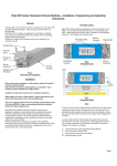
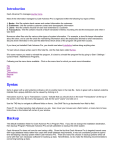
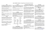
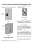
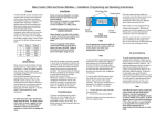
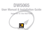
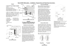
Rako RML1200 Dimmer
Modules – Installation, Programming and Operating Instructions.
Rako RML1200
is a digital,
hard-fired,
leading edge
dimmer module
suitable for use
with mains
voltage
tungsten
lighting, low
voltage
tungsten with
appropriate transformers and cold
cathode lamps.
Rako RD dimmer modules are designed
to be installed in a lighting circuit and
are controlled from Rako scene-sender
panels transmitting Rakom encoded
radio signals.
Setup Button
Aerial
Fixing hole
LED
Supply Terminals
Installation
Before commencing installation of a
Rako dimmer module first read this
instruction manual carefully.
Rako Controls Ltd accepts no
responsibility for any damage or
injury caused by incorrect
installation of a Rako product.
Installation should only be carried
out by a competent
electrician.
Never attempt to connect a Rako
dimmer or remove the terminal
covers without first isolating the
circuit at the fuse/MCB board.
The circuit supplying a Rako dimmer
should always be protected by either
a 5A fuse or 6A MCB. Under no
circumstances should any protection
devices with higher ratings be used.
Always mount the unit vertically and
ensure that the ventilation slots are
not covered.
Whilst the Rako dimmer modules are
designed to be completely maintenance
free the units should be mounted in a
position where access can be gained
should there be a fault or re-addressing
of the unit be necessary (see ‘Set-up
and Addressing’).
Permissible loadings.
Mains voltage tungsten – full rating i.e.
1200w.
Transformer fed loads, allow 10% derating, i.e. 1080w of nominal lamp load.
Note:
In the case of transformer fed loads
only transformers suitable for use with
leading edge dimmers should be used.
If in doubt contact the Rako customer
help-line on 01634 226666.
Connection
To install a Rako dimmer module isolate
the supply then undo two screws to
remove the lid, giving access to the
supply/load terminals. The necessary
Fuse
Fixing hole
connections are indicated on the main
circuit board. The notation is as follows:
Load Terminals
Cable Clamp
lighting switch can also be used as an
override in the event that the batteries
in a Rako control panel are not replaced
when the low-battery warning signals
indicate that this should be done.
Set-up and Addressing
Before any lighting scenes can be
programmed (see the wall panel or
handheld instruction manual) the
receivers need to be addressed.
SUPPLY
Fig 2.
Connection Detail
LOAD
The cables should be secured using the
two cable clamps fitted to the base of
the unit.
Note:
To ensure that the cable clamping
operates satisfactorily the cabling both
supplying the dimmer and to the load
should be a minimum of 1.0mm 2 with
double safety insulation and the wires
should be stripped to ensure that the
cable bar within the terminal cover
clamps firmly on both sets of insulation.
Alternative cable exit can be achieved
through the rear face of the unit. A
knockout area is provided in the plastic
next to each of the terminal blocks.
Once the supply and load cables are
connected replace the lid securely
before restoring power to the unit.
Rako dimmer modules are not designed
for loop in/loop out connections. Should
it be necessary to loop the supply on to
further fittings then a junction box
should be connected in circuit to
facilitate this.
When power is connected the Rako unit
will fade to a full-on setting. In this way
it is possible to leave a conventional
lighting switch in circuit to simply fade
between full-on and off settings without
the use of a Rako control panel. Such a
To avoid interference between rooms or
neighbouring installations a Rako
system should be set to an address
other than the factory default of House
1 Room 4. The preferred addressing
method is to select a logical House
address number for the project,
separate Room addresses for each
room within the house and then
sequential Channel numbers for each
receiver within each room (see Fig.5)
i.e. Channel 1 for the 1 st receiver,
Channel 2 for the 2 nd etc. The House
and Room addresses are set using the
DIP switches on the back of a Rako
controller (see Fig.4) and the Channel
address is set by ‘stepping’ through the
channel numbers with a panel in
programming mode (see Step 3
overleaf) and then sending this number
(along with the House and Room
address) to a receiver (Step 5).
Setting the address switches.
Each Rako transmitter has two, 8 way
banks of switches for setting its
address. The two sets of switches allow
the user to choose from 256 house
addresses and 256 room addresses. To
set the address, unclip the rear cover
whereupon the banks of switches will
be now become visible. To set an
address, use a small terminal
screwdriver or similar device and
carefully move some of the switches
into the ‘ON’ position. Addressing uses
binary encoding and the value of the
switches is shown below.
House address
= 128+16=144
ROOM
128
64
32
16
8
4
2
1
Initial Addressing of RML1200 Dimmer
In the following procedure both the controllers (wallpanels and hand held remotes) and the receivers have an automatic time out after
approximately 3 minutes when in programming or set-up mode. This feature avoids the possibility of either being left permanently in
programming or set-up mode. This may cause confusion if either the controller or receiver times out before the procedure is complete. It is worth
becoming familiar with the procedures before starting the addressing procedure. If at any time it is necessary to start again the controllers can be
returned to normal mode by pressing the ‘Off’ button and the receivers by resetting the electrical supply.
Step 2
O N
B IN A R Y V A L U E
H O U SE
128
64
32
16
8
4
2
1
O N
B IN A R Y V A L U E
Note: Any control panels set with the
same address will act as two or multi
way controls.
Room address
= 32+4=36.
Fig 3.
Addressing Switches
Step 1
Put controller into
programming
mode.
Set Address
switches on
controller
Pick a House Address from 1-255 (keep same
address for all panels in house)
Select Room Addresses from 1-255 for each
room. (Room 0 is Master House control)
Channel 2
House 144
Room 6
Channel 1
TIP
Press the scene
button first
Press and hold a
scene button and
both raise & lower
buttons together,
After 5 seconds the
LED on the panel
starts to flash. The
panel is now in
Programming
Mode. Release the
buttons
Table 1
Note:
ButtonAction 1Step
up one
& enter programming mode at Channel 0. It is not possible to give a receiver an address of Channel 0, but this gives a consistent starting point
A Rako
panelchannel
will always
Ident 2Step down one channel &
Ident 3Ident 4StoreNo action OffExit
Channel 2
House 144
Room 5
Channel 1
NO
programming
Note:
When in Programming Mode the buttons have functions as detailed in
table 1.
144
YES
Fig 5.
Addressing Example
Notes on addressing.
A module will not receive an address of
House 0 (All switches set to off)
A dimmer will respond to, but not receive an
address of Room 0 (All switches set to off).
This Room 0 address is used for ‘Master
House’ control
A dimmer cannot be set to channel 0.
To program a lighting scene see Wall panel or
Hand held manual.
Care and maintenance
A Rako receiver module contains no user
serviceable parts. Should for any reason you
need to contact us please contact us via our
website www.rakocontrols.com or by phoning
our customer help line on 01634 226666
Step 3
Press button 1 once to step up one channel.
If this is the desired channel i.e. Channel 1 (for the 1st receiver)
then go to Step 4. If not, press button 1 again to step up to
channel 2 (for the 2nd receiver), press again to step to channel 3
etc until the desired channel number is reached (maximum = 15).
It is this channel number (along with the House and Room
address) that is sent to the receiver in step 5. If it necessary to
step down a channel at any point, press button 2 once
Is the
Controller
Still in programming
Mode (LED still
flashing)?
If some receivers are already addressed to a the wall panel then they
will ‘flash’ their connected lamps as their channel number is reached during
the stepping procedure, this allows the user to ‘identify’ which channel numbers
are already taken. To add a new receiver to an existing installation step up through
the channels until a channel number is reached where no receiver flashes a load, this is
then an available channel. If at any point there is uncertainty as to whether a receiver
actually flashed its load then button 3 will flash the load but without stepping up or
down a channel. If all of the loads flash then this indicates that the current address is
Channel 0.
Note: If it is not possible to see the connected lamps flashing when stepping through
the channels it is possible to tell from the LEDs in the receivers which will momentarily
go solid when their channel address is reached.
Go to the receiver to be addressed
YES
Step 4
Is there
another receiver in
the room to be
addressed?
Remove the top cover from the upper part of the RDL1200
case. Use a slim tool to push the ident button that is located
down the ident access hole in the case. A blue LED will
illuminate inside the case, visible through the case vent
holes. Hold the button down for 5 seconds & the LED will
start to flash, release the button. LED continues to flash
indicating that dimmer is in Programming Mode
Step 5
Press the button 3 to
send the ident of the
channel selected in
Step 3. The dimmer
will automatically
return to normal
mode (it’s blue LED
goes out).
The controller will
remain in
Programming Mode
ready to ident
further dimmers.
NO
Step 6
Press the Off
button to exit
the controller
from
Programming
Mode