1
™
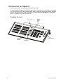
Lighting Control Console
User Manual
Version 1.9.8
C o p y r i g h t © 2 0 1 1 E le c tr o n i c T h e a t r e C o n t r o l s , I n c .
All Rights reserved.
P r o d u c t in f o r m a t i on a n d s p e c i f i c a t i o n s s u bj e c t t o c h a n g e .
Part Number:4330M1210-1.9.8 Rev A
R e le a s ed : 2 0 1 1 - 1 1
E T C , E le m e n t , E o s , I o n , E m p h a s i s , E x p r e s s i o n , In s ig h t , I m a g i n e, F o c u s , E x p r e s s , U n i s o n ,
O b s e s s i o n I I, E T C N e t 2 , E D M X , R e v o l u t i o n , a n d S e n s o r + , a r e e it h e r r e g i s t e r e d t r a d e m ar k s o r
tr a d e m a r k s o f E l e c tr o n i c T h ea t r e C o n t r o l s , I n c . i n t h e U n i t e d S t a t e s a n d o t h e r c o u n tr i e s .
E T C p e r m i ts t h e r e p r o d u c t i o n o f m a t e r i a l s i n t h i s m a n u a l o n l y f o r n o n - c o m me r c i a l p u r p o s e s .
A l l o t h e r r i g ht s a r e r e s e r v e d b y E T C .
E T C i n t e n d s t hi s d o c u m e n t , w h e t h e r p r i n te d o r el e c t r o n i c , t o b e p r o v i d e d i n i t s e n t i r e ty .
Table of Contents
Introduction . . . . . . . . . . . . . . . . . . . . . . . . . . 1
Welcome to Element . . . . . . . . . . . . . . . . . . . . . . . . . . . . . . . . . . . . .2
Using this Manual . . . . . . . . . . . . . . . . . . . . . . . . . . . . . . . . . . . . . . . .2
Register Your Element . . . . . . . . . . . . . . . . . . . . . . . . . . . . . . . . . . . .3
Online Element User Forums . . . . . . . . . . . . . . . . . . . . . . . . . . . . . . .3
Help from ETC Technical Services . . . . . . . . . . . . . . . . . . . . . . . . . .4
Other Reference Materials . . . . . . . . . . . . . . . . . . . . . . . . . . . . . . . . .5
On Screen Prompts . . . . . . . . . . . . . . . . . . . . . . . . . . . . . . . . . . .5
Help System . . . . . . . . . . . . . . . . . . . . . . . . . . . . . . . . . . . . . . . .5
Important Lighting Concepts . . . . . . . . . . . . . . . . . . . . . . . . . . . .5
Quick Start . . . . . . . . . . . . . . . . . . . . . . . . . . . . . . . . . . . . . . . . . .5
Chapter 1
Quick Start . . . . . . . . . . . . . . . . . . . . . . . . . . 7
Getting Started . . . . . . . . . . . . . . . . . . . . . . . . . . . . . . . . . . . . . . . . . .8
Hardware . . . . . . . . . . . . . . . . . . . . . . . . . . . . . . . . . . . . . . . . . . . . . .8
Power Up the Console. . . . . . . . . . . . . . . . . . . . . . . . . . . . . . . . .8
Power Down the Console . . . . . . . . . . . . . . . . . . . . . . . . . . . . . .8
Getting the Lights On . . . . . . . . . . . . . . . . . . . . . . . . . . . . . . . . . . . . .9
Setting Levels Via Channel Faders . . . . . . . . . . . . . . . . . . . . . . .9
Setting Levels Via the Control Keypad . . . . . . . . . . . . . . . . . . . .9
Recording a Lighting Look . . . . . . . . . . . . . . . . . . . . . . . . . . . . . . . .10
Recording a Submaster . . . . . . . . . . . . . . . . . . . . . . . . . . . . . . .10
Chapter 2
Element Overview. . . . . . . . . . . . . . . . . . . . 11
Console Geography . . . . . . . . . . . . . . . . . . . . . . . . . . . . . . . . . . . . .12
Control Keypad Layout . . . . . . . . . . . . . . . . . . . . . . . . . . . . . . .13
Terminology . . . . . . . . . . . . . . . . . . . . . . . . . . . . . . . . . . . . . . . .14
Littlites® . . . . . . . . . . . . . . . . . . . . . . . . . . . . . . . . . . . . . . . . . . . . . . . . . . . . . 14
Cleaning Element . . . . . . . . . . . . . . . . . . . . . . . . . . . . . . . . . . .14
Outputting DMX . . . . . . . . . . . . . . . . . . . . . . . . . . . . . . . . . . . . .15
Console Capacities . . . . . . . . . . . . . . . . . . . . . . . . . . . . . . . . . . . . .16
Output Parameters . . . . . . . . . . . . . . . . . . . . . . . . . . . . . . . . . .16
Channel Counts . . . . . . . . . . . . . . . . . . . . . . . . . . . . . . . . . . . . .16
Cues and Cue List . . . . . . . . . . . . . . . . . . . . . . . . . . . . . . . . . . .16
Record Targets . . . . . . . . . . . . . . . . . . . . . . . . . . . . . . . . . . . . .16
Faders . . . . . . . . . . . . . . . . . . . . . . . . . . . . . . . . . . . . . . . . . . . .16
Chapter 3
System Basics . . . . . . . . . . . . . . . . . . . . . . 17
The Central Information Area (CIA) . . . . . . . . . . . . . . . . . . . . . . . . .18
Browser . . . . . . . . . . . . . . . . . . . . . . . . . . . . . . . . . . . . . . . . . . .18
i
Collapse/Expand the CIA. . . . . . . . . . . . . . . . . . . . . . . . . . . . . .18
Lock the CIA . . . . . . . . . . . . . . . . . . . . . . . . . . . . . . . . . . . . . . .18
Command Line Prompt . . . . . . . . . . . . . . . . . . . . . . . . . . . . . . .18
Using Softkeys . . . . . . . . . . . . . . . . . . . . . . . . . . . . . . . . . . . . . . . . .19
Context Sensitive Softkeys . . . . . . . . . . . . . . . . . . . . . . . . . . . .19
Changing Softkey Pages . . . . . . . . . . . . . . . . . . . . . . . . . . . . . .19
Using the Browser . . . . . . . . . . . . . . . . . . . . . . . . . . . . . . . . . . . . . .20
Display Control and Navigation . . . . . . . . . . . . . . . . . . . . . . . . . . . .21
Opening and Closing Displays. . . . . . . . . . . . . . . . . . . . . . . . . .21
Swap Displays . . . . . . . . . . . . . . . . . . . . . . . . . . . . . . . . . . . . . .21
Scrolling within a Display . . . . . . . . . . . . . . . . . . . . . . . . . . . . . .22
Expanding Displays . . . . . . . . . . . . . . . . . . . . . . . . . . . . . . . . . .22
[Data] Key . . . . . . . . . . . . . . . . . . . . . . . . . . . . . . . . . . . . . . . . .22
[Label] Key. . . . . . . . . . . . . . . . . . . . . . . . . . . . . . . . . . . . . . . . .22
[Recall From], [Copy To], {Replace With}, and {Move To}. . . . .22
Using Flexichannel . . . . . . . . . . . . . . . . . . . . . . . . . . . . . . . . . .23
Using [Format] . . . . . . . . . . . . . . . . . . . . . . . . . . . . . . . . . . . . . . . . .24
Zooming Displays . . . . . . . . . . . . . . . . . . . . . . . . . . . . . . . . . . .25
Chapter 4
Managing Show Files . . . . . . . . . . . . . . . . . 27
Create a New Show File. . . . . . . . . . . . . . . . . . . . . . . . . . . . . . . . . .28
Open an Existing Show File . . . . . . . . . . . . . . . . . . . . . . . . . . . . . . .28
Selective Partial Show Opening . . . . . . . . . . . . . . . . . . . . . . . .30
Merging Show Files . . . . . . . . . . . . . . . . . . . . . . . . . . . . . . . . . . . . .31
Printing a Show File . . . . . . . . . . . . . . . . . . . . . . . . . . . . . . . . . . . . .32
Saving the Current Show File. . . . . . . . . . . . . . . . . . . . . . . . . . . . . .34
Using Quick Save . . . . . . . . . . . . . . . . . . . . . . . . . . . . . . . . . . . . . . .34
Using Save As . . . . . . . . . . . . . . . . . . . . . . . . . . . . . . . . . . . . . . . . .34
Importing Show Files . . . . . . . . . . . . . . . . . . . . . . . . . . . . . . . . . . . .35
Exporting a Show File . . . . . . . . . . . . . . . . . . . . . . . . . . . . . . . . . . .35
Deleting a File . . . . . . . . . . . . . . . . . . . . . . . . . . . . . . . . . . . . . . . . .35
Chapter 5
Setup . . . . . . . . . . . . . . . . . . . . . . . . . . . . . 37
Opening Setup . . . . . . . . . . . . . . . . . . . . . . . . . . . . . . . . . . . . . . . . .38
Show . . . . . . . . . . . . . . . . . . . . . . . . . . . . . . . . . . . . . . . . . . . . .38
Desk. . . . . . . . . . . . . . . . . . . . . . . . . . . . . . . . . . . . . . . . . . . . . .40
Chapter 6
Patch. . . . . . . . . . . . . . . . . . . . . . . . . . . . . . 45
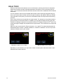
About Patch . . . . . . . . . . . . . . . . . . . . . . . . . . . . . . . . . . . . . . . . . . .46
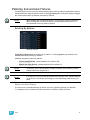
Patching Conventional Fixtures . . . . . . . . . . . . . . . . . . . . . . . . . . . .47
Patching By Address . . . . . . . . . . . . . . . . . . . . . . . . . . . . . . . . .47
Patching By Channel . . . . . . . . . . . . . . . . . . . . . . . . . . . . . . . . .48
ii
Element User Manual
Range Patching . . . . . . . . . . . . . . . . . . . . . . . . . . . . . . . . . . . . .48
Labeling . . . . . . . . . . . . . . . . . . . . . . . . . . . . . . . . . . . . . . . . . . .48
[At] [Next] . . . . . . . . . . . . . . . . . . . . . . . . . . . . . . . . . . . . . . . . . .48
Using EDMX vs Port/Offset . . . . . . . . . . . . . . . . . . . . . . . . . . . .49
Creating a compound channel. . . . . . . . . . . . . . . . . . . . . . . . . .49
Replace . . . . . . . . . . . . . . . . . . . . . . . . . . . . . . . . . . . . . . . . . . .50
Patching Scrollers . . . . . . . . . . . . . . . . . . . . . . . . . . . . . . . . . . . . . .51
Patching Moving Lights, LEDs, and Accessories . . . . . . . . . . . . . . .52
Using {Offset} in Patch. . . . . . . . . . . . . . . . . . . . . . . . . . . . . . . .53
Display Pages in Patch . . . . . . . . . . . . . . . . . . . . . . . . . . . . . . . . . .54
{Patch} Display and Settings . . . . . . . . . . . . . . . . . . . . . . . . . . .54
Attributes . . . . . . . . . . . . . . . . . . . . . . . . . . . . . . . . . . . . . . . . . .56
Database . . . . . . . . . . . . . . . . . . . . . . . . . . . . . . . . . . . . . . . . . .58
Using the Scroller Editor. . . . . . . . . . . . . . . . . . . . . . . . . . . . . . . . . .59
Using the Picker. . . . . . . . . . . . . . . . . . . . . . . . . . . . . . . . . . . . .59
Using the Editor . . . . . . . . . . . . . . . . . . . . . . . . . . . . . . . . . . . . .60
Calibrating a Scroller . . . . . . . . . . . . . . . . . . . . . . . . . . . . . . . . . . . .63
Dimmer Doubling . . . . . . . . . . . . . . . . . . . . . . . . . . . . . . . . . . . . . . .64
Moving and Copying Channels . . . . . . . . . . . . . . . . . . . . . . . . . . . .64
Unpatch a Channel. . . . . . . . . . . . . . . . . . . . . . . . . . . . . . . . . . . . . .65
Deleting Channels . . . . . . . . . . . . . . . . . . . . . . . . . . . . . . . . . . . . . .65
Clearing the Patch . . . . . . . . . . . . . . . . . . . . . . . . . . . . . . . . . . . . . .65
Update Library . . . . . . . . . . . . . . . . . . . . . . . . . . . . . . . . . . . . . . . . .66
Fixture Editor . . . . . . . . . . . . . . . . . . . . . . . . . . . . . . . . . . . . . . . . . .67
Creating a New Fixture . . . . . . . . . . . . . . . . . . . . . . . . . . . . . . .67
Copying a Fixture. . . . . . . . . . . . . . . . . . . . . . . . . . . . . . . . . . . .72
Importing a Custom Fixture . . . . . . . . . . . . . . . . . . . . . . . . . . . .72
Snap Parameters. . . . . . . . . . . . . . . . . . . . . . . . . . . . . . . . . . . .73
Chapter 7
Basic Manual Control . . . . . . . . . . . . . . . . . 75
Using Channel Faders . . . . . . . . . . . . . . . . . . . . . . . . . . . . . . . . . . .76
Selecting Channels . . . . . . . . . . . . . . . . . . . . . . . . . . . . . . . . . . . . .77
Select Channels From the Keypad . . . . . . . . . . . . . . . . . . . . . .77
Offset . . . . . . . . . . . . . . . . . . . . . . . . . . . . . . . . . . . . . . . . . . . . .78
Deselecting Channels . . . . . . . . . . . . . . . . . . . . . . . . . . . . . . . .78
Setting Intensity . . . . . . . . . . . . . . . . . . . . . . . . . . . . . . . . . . . . . . . .79
Level Wheel . . . . . . . . . . . . . . . . . . . . . . . . . . . . . . . . . . . . . . . .80
Select Last . . . . . . . . . . . . . . . . . . . . . . . . . . . . . . . . . . . . . . . . . . . .80
Using +% and -% . . . . . . . . . . . . . . . . . . . . . . . . . . . . . . . . . . . . . . .81
iii
Channel Intensity . . . . . . . . . . . . . . . . . . . . . . . . . . . . . . . . . . . .81
Remainder Dim . . . . . . . . . . . . . . . . . . . . . . . . . . . . . . . . . . . . . . . .82
Sneak . . . . . . . . . . . . . . . . . . . . . . . . . . . . . . . . . . . . . . . . . . . . . . . .83
Channel Check . . . . . . . . . . . . . . . . . . . . . . . . . . . . . . . . . . . . . . . . .84
Address at Level. . . . . . . . . . . . . . . . . . . . . . . . . . . . . . . . . . . . . . . .84
Address Check . . . . . . . . . . . . . . . . . . . . . . . . . . . . . . . . . . . . . . . . .84
Flash. . . . . . . . . . . . . . . . . . . . . . . . . . . . . . . . . . . . . . . . . . . . . . . . .85
Moving Light Control . . . . . . . . . . . . . . . . . . . . . . . . . . . . . . . . . . . .85
Chapter 8
Storing and Using Submasters . . . . . . . . . . 87
About Submasters . . . . . . . . . . . . . . . . . . . . . . . . . . . . . . . . . . . . . .88
Recording a Submaster . . . . . . . . . . . . . . . . . . . . . . . . . . . . . . . . . .88
Submaster Displays. . . . . . . . . . . . . . . . . . . . . . . . . . . . . . . . . .89
Additive, Inhibitive, or Effectsub. . . . . . . . . . . . . . . . . . . . . . . . .89
Proportional vs. Intensity Master . . . . . . . . . . . . . . . . . . . . . . . .89
HTP vs. LTP . . . . . . . . . . . . . . . . . . . . . . . . . . . . . . . . . . . . . . .90
Exclusive Submasters . . . . . . . . . . . . . . . . . . . . . . . . . . . . . . . .90
Independent. . . . . . . . . . . . . . . . . . . . . . . . . . . . . . . . . . . . . . . .90
Shield. . . . . . . . . . . . . . . . . . . . . . . . . . . . . . . . . . . . . . . . . . . . .90
Submaster Background State . . . . . . . . . . . . . . . . . . . . . . . . . .91
Submaster {Restore} Mode . . . . . . . . . . . . . . . . . . . . . . . . . . . .91
Updating a Submaster . . . . . . . . . . . . . . . . . . . . . . . . . . . . . . . .92
Labeling a Submaster . . . . . . . . . . . . . . . . . . . . . . . . . . . . . . . .92
Deleting a Submaster . . . . . . . . . . . . . . . . . . . . . . . . . . . . . . . .92
Paging Submasters . . . . . . . . . . . . . . . . . . . . . . . . . . . . . . . . . .93
Using Bump Button Timing With Submasters . . . . . . . . . . . . . . . . .94
Controlling Subfades Manually . . . . . . . . . . . . . . . . . . . . . . . . .94
Controlling Submasters from the Command Line . . . . . . . . . . .94
Submaster List . . . . . . . . . . . . . . . . . . . . . . . . . . . . . . . . . . . . . . . . .95
Editing Submasters . . . . . . . . . . . . . . . . . . . . . . . . . . . . . . . . . .95
Chapter 9
Working with the Cue List . . . . . . . . . . . . . . 97
Basic Cueing . . . . . . . . . . . . . . . . . . . . . . . . . . . . . . . . . . . . . . . . . .98
Cue Numbering . . . . . . . . . . . . . . . . . . . . . . . . . . . . . . . . . . . . .98
Recording Cues in Live . . . . . . . . . . . . . . . . . . . . . . . . . . . . . . . . . .99
Using Record . . . . . . . . . . . . . . . . . . . . . . . . . . . . . . . . . . . . . . .99
Selective Storing Cues using [Record] . . . . . . . . . . . . . . . . . . .99
Using [Cue Only / Track] . . . . . . . . . . . . . . . . . . . . . . . . . . . . .100
Move Fade . . . . . . . . . . . . . . . . . . . . . . . . . . . . . . . . . . . . . . . . . . .102
Timing. . . . . . . . . . . . . . . . . . . . . . . . . . . . . . . . . . . . . . . . . . . . . . .103
Setting Cue Level Timing. . . . . . . . . . . . . . . . . . . . . . . . . . . . .103
[Time][/] . . . . . . . . . . . . . . . . . . . . . . . . . . . . . . . . . . . . . . . . . .104
Delay Time. . . . . . . . . . . . . . . . . . . . . . . . . . . . . . . . . . . . . . . .104
Assigning Cue Attributes . . . . . . . . . . . . . . . . . . . . . . . . . . . . .104
iv
Element User Manual
Clearing Cue Attributes . . . . . . . . . . . . . . . . . . . . . . . . . . . . . .106
Flags. . . . . . . . . . . . . . . . . . . . . . . . . . . . . . . . . . . . . . . . . . . . . . . .107
Block . . . . . . . . . . . . . . . . . . . . . . . . . . . . . . . . . . . . . . . . . . . .107
Preheat . . . . . . . . . . . . . . . . . . . . . . . . . . . . . . . . . . . . . . . . . .108
Using the Execute List . . . . . . . . . . . . . . . . . . . . . . . . . . . . . . .108
Modifying Cues Live . . . . . . . . . . . . . . . . . . . . . . . . . . . . . . . . . . . .109
Using [At] [Enter] . . . . . . . . . . . . . . . . . . . . . . . . . . . . . . . . . . .109
Using Record . . . . . . . . . . . . . . . . . . . . . . . . . . . . . . . . . . . . . .109
[Update] . . . . . . . . . . . . . . . . . . . . . . . . . . . . . . . . . . . . . . . . . .110
Recording and Editing Cues from Blind . . . . . . . . . . . . . . . . . . . . .113
From the Cue Spreadsheet . . . . . . . . . . . . . . . . . . . . . . . . . . .114
Deleting Cues . . . . . . . . . . . . . . . . . . . . . . . . . . . . . . . . . . . . . . . . .116
In Track Mode . . . . . . . . . . . . . . . . . . . . . . . . . . . . . . . . . . . . .116
In Cue Only Mode . . . . . . . . . . . . . . . . . . . . . . . . . . . . . . . . . .116
Chapter 10
Using Groups and Intensity Palettes. . . . . 117
Recording Groups Live. . . . . . . . . . . . . . . . . . . . . . . . . . . . . . . . . .118
Ordered Channels . . . . . . . . . . . . . . . . . . . . . . . . . . . . . . . . . .118
Offset . . . . . . . . . . . . . . . . . . . . . . . . . . . . . . . . . . . . . . . . . . . .119
Editing and Updating Groups in Live . . . . . . . . . . . . . . . . . . . .119
Selecting Groups . . . . . . . . . . . . . . . . . . . . . . . . . . . . . . . . . . . . . .119
Deleting Groups. . . . . . . . . . . . . . . . . . . . . . . . . . . . . . . . . . . .119
Group List. . . . . . . . . . . . . . . . . . . . . . . . . . . . . . . . . . . . . . . . . . . .120
Open the Group List . . . . . . . . . . . . . . . . . . . . . . . . . . . . . . . .120
Ordered View and Numeric View. . . . . . . . . . . . . . . . . . . . . . .120
Editing Groups from the Group List . . . . . . . . . . . . . . . . . . . . .120
Recording Intensity Palettes Live . . . . . . . . . . . . . . . . . . . . . . . . . .121
Using Intensity Palettes . . . . . . . . . . . . . . . . . . . . . . . . . . . . . . . . .122
Applying Palettes . . . . . . . . . . . . . . . . . . . . . . . . . . . . . . . . . . .122
Recalling Palettes . . . . . . . . . . . . . . . . . . . . . . . . . . . . . . . . . .122
Chapter 11
Cue Playback . . . . . . . . . . . . . . . . . . . . . . 123
Introduction to Playback . . . . . . . . . . . . . . . . . . . . . . . . . . . . . . . . .124
Playback Controls . . . . . . . . . . . . . . . . . . . . . . . . . . . . . . . . . .124
Selected Cue . . . . . . . . . . . . . . . . . . . . . . . . . . . . . . . . . . . . . . . . .125
Live / Blind . . . . . . . . . . . . . . . . . . . . . . . . . . . . . . . . . . . . . . . .125
Out-of-Sequence Cues. . . . . . . . . . . . . . . . . . . . . . . . . . . . . . . . . .126
Go To Cue . . . . . . . . . . . . . . . . . . . . . . . . . . . . . . . . . . . . . . . .127
Playback Fader Controls . . . . . . . . . . . . . . . . . . . . . . . . . . . . . . . .128
Go and Stop/Back . . . . . . . . . . . . . . . . . . . . . . . . . . . . . . . . . .128
[Go To Cue] [0] . . . . . . . . . . . . . . . . . . . . . . . . . . . . . . . . . . . .128
[Go To Cue] [Out] . . . . . . . . . . . . . . . . . . . . . . . . . . . . . . . . . .128
Manual Master Option . . . . . . . . . . . . . . . . . . . . . . . . . . . . . . . . . .131
v
Chapter 12
Using Moving Lights and Palettes. . . . . . . 133
Moving Light Control . . . . . . . . . . . . . . . . . . . . . . . . . . . . . . . . . . .134
ML Control . . . . . . . . . . . . . . . . . . . . . . . . . . . . . . . . . . . . . . . .134
Using the Color Picker . . . . . . . . . . . . . . . . . . . . . . . . . . . . . . .135
Lamp Controls . . . . . . . . . . . . . . . . . . . . . . . . . . . . . . . . . . . . .136
Automark . . . . . . . . . . . . . . . . . . . . . . . . . . . . . . . . . . . . . . . . .137
About Palettes . . . . . . . . . . . . . . . . . . . . . . . . . . . . . . . . . . . . . . . .138
Palette Types . . . . . . . . . . . . . . . . . . . . . . . . . . . . . . . . . . . . . . . . .138
Intensity Palettes . . . . . . . . . . . . . . . . . . . . . . . . . . . . . . . . . . .138
Focus Palettes . . . . . . . . . . . . . . . . . . . . . . . . . . . . . . . . . . . . .138
Color Palettes . . . . . . . . . . . . . . . . . . . . . . . . . . . . . . . . . . . . .138
Beam Palettes . . . . . . . . . . . . . . . . . . . . . . . . . . . . . . . . . . . . .138
Storing Palettes Live . . . . . . . . . . . . . . . . . . . . . . . . . . . . . . . . . . .139
Storing Palettes with [Record] . . . . . . . . . . . . . . . . . . . . . . . . .139
Using Palettes . . . . . . . . . . . . . . . . . . . . . . . . . . . . . . . . . . . . . . . .141
Applying Palettes . . . . . . . . . . . . . . . . . . . . . . . . . . . . . . . . . . .141
Recalling Palettes . . . . . . . . . . . . . . . . . . . . . . . . . . . . . . . . . .142
Editing Palettes Live . . . . . . . . . . . . . . . . . . . . . . . . . . . . . . . . . . . .143
Rerecord . . . . . . . . . . . . . . . . . . . . . . . . . . . . . . . . . . . . . . . . .143
Update . . . . . . . . . . . . . . . . . . . . . . . . . . . . . . . . . . . . . . . . . . .143
Editing Palettes in Blind . . . . . . . . . . . . . . . . . . . . . . . . . . . . . . . . .144
Editing in Blind . . . . . . . . . . . . . . . . . . . . . . . . . . . . . . . . . . . . .144
Editing Palettes in Spreadsheet View . . . . . . . . . . . . . . . . . . .145
Deleting Palettes . . . . . . . . . . . . . . . . . . . . . . . . . . . . . . . . . . .145
Chapter 13
Creating and Using Effects . . . . . . . . . . . . 147
About Effects . . . . . . . . . . . . . . . . . . . . . . . . . . . . . . . . . . . . . . . . .148
The Effect List . . . . . . . . . . . . . . . . . . . . . . . . . . . . . . . . . . . . .149
Effects Editor . . . . . . . . . . . . . . . . . . . . . . . . . . . . . . . . . . . . . .150
Effect Status Display . . . . . . . . . . . . . . . . . . . . . . . . . . . . . . . .154
Step Effects . . . . . . . . . . . . . . . . . . . . . . . . . . . . . . . . . . . . . . . . . .155
Program a Step Effect . . . . . . . . . . . . . . . . . . . . . . . . . . . . . . .156
Absolute Effects . . . . . . . . . . . . . . . . . . . . . . . . . . . . . . . . . . . . . . .157
Program an Absolute Effect. . . . . . . . . . . . . . . . . . . . . . . . . . .158
Multiple Intensity HTP Effects . . . . . . . . . . . . . . . . . . . . . . . . . . . .159
Relative Effects . . . . . . . . . . . . . . . . . . . . . . . . . . . . . . . . . . . . . . .160
Focus Effects . . . . . . . . . . . . . . . . . . . . . . . . . . . . . . . . . . . . . .160
Color Effects . . . . . . . . . . . . . . . . . . . . . . . . . . . . . . . . . . . . . .161
Linear Effects. . . . . . . . . . . . . . . . . . . . . . . . . . . . . . . . . . . . . .161
Define a Pattern Shape . . . . . . . . . . . . . . . . . . . . . . . . . . . . . .162
Program a New Relative Effect . . . . . . . . . . . . . . . . . . . . . . . .162
Apply an Existing Effect . . . . . . . . . . . . . . . . . . . . . . . . . . . . . . . . .163
Editing Effects Live . . . . . . . . . . . . . . . . . . . . . . . . . . . . . . . . .163
Stop an Effect . . . . . . . . . . . . . . . . . . . . . . . . . . . . . . . . . . . . .163
Deleting an Effect . . . . . . . . . . . . . . . . . . . . . . . . . . . . . . . . . .163
Effects on Submasters . . . . . . . . . . . . . . . . . . . . . . . . . . . . . . . . . .164
vi
Element User Manual
Recording an Effect to a Submaster . . . . . . . . . . . . . . . . . . . .164
Running an Effect from a Submaster. . . . . . . . . . . . . . . . . . . .164
Delaying Effects in Cues and Submasters . . . . . . . . . . . . . . . . . . .165
Chapter 14
Using About . . . . . . . . . . . . . . . . . . . . . . . 167
About [About] . . . . . . . . . . . . . . . . . . . . . . . . . . . . . . . . . . . . . . . . .168
[About] . . . . . . . . . . . . . . . . . . . . . . . . . . . . . . . . . . . . . . . . . . .169
About System . . . . . . . . . . . . . . . . . . . . . . . . . . . . . . . . . . . . .169
About Channel . . . . . . . . . . . . . . . . . . . . . . . . . . . . . . . . . . . . .171
About Address . . . . . . . . . . . . . . . . . . . . . . . . . . . . . . . . . . . . .172
About Cue . . . . . . . . . . . . . . . . . . . . . . . . . . . . . . . . . . . . . . . .175
About IFCB Palettes . . . . . . . . . . . . . . . . . . . . . . . . . . . . . . . .175
Chapter 15
Advanced Manual Control. . . . . . . . . . . . . 177
Using [Copy To] . . . . . . . . . . . . . . . . . . . . . . . . . . . . . . . . . . . . . . .178
Using [Recall From] . . . . . . . . . . . . . . . . . . . . . . . . . . . . . . . . . . . .178
Using {Move To}. . . . . . . . . . . . . . . . . . . . . . . . . . . . . . . . . . . . . . .179
Using {Make Absolute} . . . . . . . . . . . . . . . . . . . . . . . . . . . . . . . . . .179
Using [Undo]. . . . . . . . . . . . . . . . . . . . . . . . . . . . . . . . . . . . . . . . . .180
Chapter 16
Using Park . . . . . . . . . . . . . . . . . . . . . . . . 181
Using Park . . . . . . . . . . . . . . . . . . . . . . . . . . . . . . . . . . . . . . . . . . .182
Park Display. . . . . . . . . . . . . . . . . . . . . . . . . . . . . . . . . . . . . . .182
Parked Values in Live . . . . . . . . . . . . . . . . . . . . . . . . . . . . . . .183
Scaled Parked Values in Live . . . . . . . . . . . . . . . . . . . . . . . . .184
Parked Addresses in Live . . . . . . . . . . . . . . . . . . . . . . . . . . . .184
Park Values from the Park Display . . . . . . . . . . . . . . . . . . . . .185
Chapter 17
Multipart Cues. . . . . . . . . . . . . . . . . . . . . . 187
About Multipart Cues . . . . . . . . . . . . . . . . . . . . . . . . . . . . . . . . . . .188
Record a Multipart Cue in Live . . . . . . . . . . . . . . . . . . . . . . . . . . . .188
Creating a New Multipart Cue in Live . . . . . . . . . . . . . . . . . . .188
Setting Multipart Cue Attributes . . . . . . . . . . . . . . . . . . . . . . . .189
Using Update in Live . . . . . . . . . . . . . . . . . . . . . . . . . . . . . . . .189
Storing a Multipart Cue in Blind . . . . . . . . . . . . . . . . . . . . . . . . . . .190
Changing a Single Part Cue to a Multipart Cue. . . . . . . . . . . .190
Changing a Multipart Cue to a Standard Cue . . . . . . . . . . . . .190
Deleting a Part from a Multipart Cue . . . . . . . . . . . . . . . . . . . .190
vii
Chapter 18
Storing and Using Curves . . . . . . . . . . . . . 191
About Curves . . . . . . . . . . . . . . . . . . . . . . . . . . . . . . . . . . . . . . . . .192
Creating and Editing Curves . . . . . . . . . . . . . . . . . . . . . . . . . . . . .193
Creating a Curve . . . . . . . . . . . . . . . . . . . . . . . . . . . . . . . . . . .193
Editing Curves . . . . . . . . . . . . . . . . . . . . . . . . . . . . . . . . . . . . .194
Applying a Curve . . . . . . . . . . . . . . . . . . . . . . . . . . . . . . . . . . . . . .195
To Channels In Patch . . . . . . . . . . . . . . . . . . . . . . . . . . . . . . .195
To Cues . . . . . . . . . . . . . . . . . . . . . . . . . . . . . . . . . . . . . . . . . .195
To Scroller Fans . . . . . . . . . . . . . . . . . . . . . . . . . . . . . . . . . . .195
Delete a Curve . . . . . . . . . . . . . . . . . . . . . . . . . . . . . . . . . . . . . . . .195
Chapter 19
Storing and Using Macros. . . . . . . . . . . . . 197
About Macros . . . . . . . . . . . . . . . . . . . . . . . . . . . . . . . . . . . . . . . . .198
Store a Macro from Live . . . . . . . . . . . . . . . . . . . . . . . . . . . . . . . . .198
Using the [Learn] key. . . . . . . . . . . . . . . . . . . . . . . . . . . . . . . .198
Macro Editor Display . . . . . . . . . . . . . . . . . . . . . . . . . . . . . . . . . . .200
Macro Modes . . . . . . . . . . . . . . . . . . . . . . . . . . . . . . . . . . . . . .201
Create a New Macro in the Macro Editor Display . . . . . . . . . .202
Edit an Existing Macro . . . . . . . . . . . . . . . . . . . . . . . . . . . . . . .203
Recall a Macro . . . . . . . . . . . . . . . . . . . . . . . . . . . . . . . . . . . . . . . .204
Stop a Macro . . . . . . . . . . . . . . . . . . . . . . . . . . . . . . . . . . . . . .204
Delete a Macro . . . . . . . . . . . . . . . . . . . . . . . . . . . . . . . . . . . . . . . .204
Appendix A
Important Concepts . . . . . . . . . . . . . . . . . 205
Important Concepts . . . . . . . . . . . . . . . . . . . . . . . . . . . . . . . . . . . .205
Channel . . . . . . . . . . . . . . . . . . . . . . . . . . . . . . . . . . . . . . . . . .205
Address . . . . . . . . . . . . . . . . . . . . . . . . . . . . . . . . . . . . . . . . . .205
Record Target . . . . . . . . . . . . . . . . . . . . . . . . . . . . . . . . . . . . .205
Cue . . . . . . . . . . . . . . . . . . . . . . . . . . . . . . . . . . . . . . . . . . . . .205
Move Instruction and Track . . . . . . . . . . . . . . . . . . . . . . . . . . .205
Tracking vs. Cue Only . . . . . . . . . . . . . . . . . . . . . . . . . . . . . . .206
Move Fade. . . . . . . . . . . . . . . . . . . . . . . . . . . . . . . . . . . . . . . .206
HTP vs. LTP . . . . . . . . . . . . . . . . . . . . . . . . . . . . . . . . . . . . . .206
Syntax Structure . . . . . . . . . . . . . . . . . . . . . . . . . . . . . . . . . . .207
Parameters and Parameter Categories . . . . . . . . . . . . . . . . . .208
Live and Blind . . . . . . . . . . . . . . . . . . . . . . . . . . . . . . . . . . . . .208
Appendix B
Element Configuration Utility. . . . . . . . . . . 209
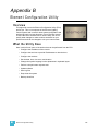
Overview . . . . . . . . . . . . . . . . . . . . . . . . . . . . . . . . . . . . . . . . . . . 209
What the Utility Does . . . . . . . . . . . . . . . . . . . . . . . . . . . . . . . . . . 209
Element Configuration Utility Reference . . . . . . . . . . . . . . . . . . . 210
General Settings. . . . . . . . . . . . . . . . . . . . . . . . . . . . . . . . . . . . . . 211
viii
Element User Manual
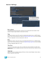
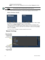
Network Settings . . . . . . . . . . . . . . . . . . . . . . . . . . . . . . . . . . . . . 214
Maintenance and Diagnostics . . . . . . . . . . . . . . . . . . . . . . . . . . . 219
Local I/O . . . . . . . . . . . . . . . . . . . . . . . . . . . . . . . . . . . . . . . . . . . . 223
RFR . . . . . . . . . . . . . . . . . . . . . . . . . . . . . . . . . . . . . . . . . . . . . . . 224
Appendix C
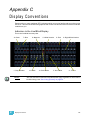
Display Conventions . . . . . . . . . . . . . . . . . 225
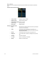
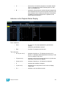
Indicators in the Live/Blind Display . . . . . . . . . . . . . . . . . . . . .225
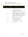
Indicators in the Playback Status Display . . . . . . . . . . . . . . . .229
Indicators in the Fader Status Display . . . . . . . . . . . . . . . . . . .230
Appendix D
Facepanel Shortcuts . . . . . . . . . . . . . . . . . 231
Facepanel and Displays . . . . . . . . . . . . . . . . . . . . . . . . . . . . . . . . 231
Operations . . . . . . . . . . . . . . . . . . . . . . . . . . . . . . . . . . . . . . . . . . 231
Appendix E
Mirror Mode. . . . . . . . . . . . . . . . . . . . . . . . 233
Displays . . . . . . . . . . . . . . . . . . . . . . . . . . . . . . . . . . . . . . . . . . . . 233
Configuring a Client PC . . . . . . . . . . . . . . . . . . . . . . . . . . . . . . . . 233
Appendix F
Remote Control. . . . . . . . . . . . . . . . . . . . . 237
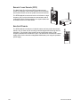
Remotes Overview . . . . . . . . . . . . . . . . . . . . . . . . . . . . . . . . . . . . .237
Phone Remote. . . . . . . . . . . . . . . . . . . . . . . . . . . . . . . . . . . . .237
Remote Focus Remote (RFR) . . . . . . . . . . . . . . . . . . . . . . . . .238
iRFR. . . . . . . . . . . . . . . . . . . . . . . . . . . . . . . . . . . . . . . . . . . . .248
aRFR . . . . . . . . . . . . . . . . . . . . . . . . . . . . . . . . . . . . . . . . . . . .248
ix
x
Element User Manual
Introduction
Welcome to the Element User Manual. This guide is a basic resource for users of the Element
control system. Additional resources available to you are listed in this introduction.
This chapter contains the following sections:
Introduction
•
Welcome to Element . . . . . . . . . . . . . . . . . . . . . . . . . . . . . . . . .2
•
Using this Manual . . . . . . . . . . . . . . . . . . . . . . . . . . . . . . . . . . .2
•
Register Your Element . . . . . . . . . . . . . . . . . . . . . . . . . . . . . . .3
•
Online Element User Forums . . . . . . . . . . . . . . . . . . . . . . . . . .3
•
Help from ETC Technical Services. . . . . . . . . . . . . . . . . . . . . .4
•
Other Reference Materials . . . . . . . . . . . . . . . . . . . . . . . . . . . .5
1
Welcome to Element
Thank you for purchasing the Element Lighting Control Console from ETC! This introduction to
Element will list all the various helpful tools available to you. In addition to this User Manual,
Element also has video tutorials, an online user forum dedicated completely to Element, and
support from ETC Technical Services. When using Element, you are never alone. Please take a
moment to learn more about the tools available to you.
Using this Manual
In order to be specific about where features and commands are found, the following naming and
text conventions will be used:
• Facepanel buttons are indicated in bold [brackets]. For example, [Live] or [Enter]. Optional
keys are indicated in <angle brackets>, for example, <Cue> or <Sub>.
• Browser menus, menu items, and commands you must perform are indicated in bold text. For
example: In the File menu, click Open. Or: Press [Record] [Enter].
• Alphanumeric keyboard buttons are indicated in all CAPS. For example, TAB or CTRL.
• Keys which are intended to be pressed or held simultaneously are indicated with the “and”
symbol. For example, [Shift] & [+].
• Softkeys and clickable buttons in the Central Information Area (CIA) are indicated in bold
{braces}. A note about <More SK> (more softkeys): this command is always indicated as
optional, and is only indicated once in an instruction regardless of how many pages of softkeys
exist. This is because there is no way to predict what softkey page you are on at any given
time. Press <More Softkeys> until you find the required command.
• References to other parts of the manual are indicated in italics. When viewing this manual
electronically, click on the reference to jump to that section of the manual.
Note:
Notes are helpful hints and information that is supplemental to the main text.
CAUTION:
A Caution statement indicates situations where there may be undefined or
unwanted consequences of an action, potential for data loss or an equipment
problem.
WARNING:
A Warning statement indicates situations where damage may occur, people may
be harmed, or there are serious or dangerous consequences of an action.
Please email comments about this manual to: [email protected]
2
Element User Manual
Register Your Element
Registering your Element system with ETC ensures that you will be notified of software and library
updates, as well as any product advisories.
When you register, you will also be enrolled in “My ETC,” a personalized ETC Web site that
provides a more direct path of communication between you and ETC.
Register now at http://www.etcconnect.com/product.registration.aspx.
Online Element User Forums
You are encouraged to visit and participate in the ETC Element User Forum, accessible from the
ETC web site (www.etcconnect.com). This gives you access to an online community of Element
users where you can read about other users’ experiences, suggestions, and questions regarding
the product as well as submit your own.
To register for the ETC Element User Forum:
Step 1:
Step 2:
Step 3:
Introduction
Go to ETC’s community web site (www.etcconnect.com/community). An introduction
page to the online community will open.
You may register for the forum using the “register” link in the introduction or by
clicking the “join” link in the upper right corner of the page.
Follow the registration instructions provided by the community page.
3
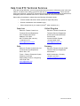
Help from ETC Technical Services
If you are having difficulties, your most convenient resources are the references given in this user
manual. To search more widely, try the ETC Web site at www.etcconnect.com. If none of these
resources is sufficient, contact ETC Technical Services directly at one of the offices identified below.
Emergency service is available from all ETC offices outside of normal business hours.
When calling for assistance, please have the following information handy:
•
Console model and serial number (located on right side panel)
•
Dimmer manufacturer and installation type
•
Other components in your system (Unison®, other consoles, etc.)
Americas
Electronic Theatre Controls Inc.
Technical Services Department
3031 Pleasant View Road
Middleton, WI 53562
800-775-4382 (USA, toll-free)
+1-608 831-4116
[email protected]
Asia
Electronic Theatre Controls Asia, Ltd.
Technical Services Department
Room 1801, 18/F
Tower 1, Phase 1 Enterprise Square
9 Sheung Yuet Road
Kowloon Bay, Kowloon, Hong Kong
+852 2799 1220
[email protected]
4
United Kingdom
Electronic Theatre Controls Ltd.
Technical Services Department
26-28 Victoria Industrial Estate
Victoria Road,
London W3 6UU England
+44 (0)20 8896 1000
[email protected]
Germany
Electronic Theatre Controls GmbH
Technical Services Department
Ohmstrasse 3
83607 Holzkirchen, Germany
+49 (80 24) 47 00-0
[email protected]
Element User Manual
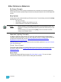
Other Reference Materials
On Screen Prompts
Element provides on screen prompts located above the command line to aid with programming.
These context-sensitive prompts will give instructions and options based on the current display and
key hits.
Help System
A help system is also contained within your Element console. To access help, press and hold [Help]
and press any key to see:
•
•
•
the name of the key
a description of what the key enables you to do
syntax examples for using the key (if applicable)
Note:
Help is included on most tangible action buttons on your Element console. This
includes most softkeys and clickable buttons as well as the traditional keys on the
keypad.
As with hard keys, the “press and hold [Help]” action can be also used with
softkeys and clickable buttons.
Important Lighting Concepts
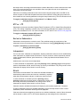
In addition to Element’s video tutorials, ETC also has a video explaining the important lighting
concepts of tracking and preset. If you are new to lighting consoles, it is highly recommended that
you take a few moments and view this video, http://www.etcconnect.com/video/BHFWhyDidMyConsoleDoThat/index.htm.
Additional lighting concepts are also explained in this User Manual, please see Important Concepts,
page 205 to learn more.
Periodic Table of Element
The Periodic Table of Element is a handy reference guide for the various concepts and components
of Element. Please visit the Periodic Table of Element, http://www.etcconnect.com/minisite/
Element/index.html.
Quick Start
To quickly get started with Element, please See “Quick Start” on page 7. For more in depth
information about Element, please continue reading this User Manual.
Introduction
5
6
Element User Manual
Chapter 1
Quick Start
This chapter will walk you through the steps of quickly getting started with Element.
This chapter contains the following sections:
1
Quick Start
•
Getting Started . . . . . . . . . . . . . . . . . . . . . . . . . . . . . . . . . . . . . .8
•
Hardware . . . . . . . . . . . . . . . . . . . . . . . . . . . . . . . . . . . . . . . . . .8
•
Getting the Lights On . . . . . . . . . . . . . . . . . . . . . . . . . . . . . . . .9
•
Recording a Lighting Look . . . . . . . . . . . . . . . . . . . . . . . . . . .10
7
Getting Started
This chapter will quickly get you started with using Element. Later chapters will go into further detail
of topics touched upon here.
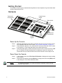
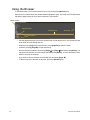
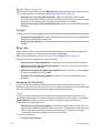
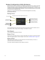
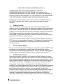
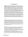
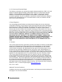
Hardware
Fader Position
Switch
Faders and
bump buttons
Power button
Control
keypad
Level
wheel
Blackout and
Grandmaster
Power Up the Console
Step 1:
Step 2:
Step 3:
Attach the appropriate power cable to the IEC connector on the rear of the console.
For a diagram of the rear of the console, See “Console Geography” on page 12.
Press the power switch (I is “on”) under the IEC connector on the rear of the console
to turn power on. This will provide power to all internal electronics.
Press the power button, located in the top left corner of the console, above the USB
port. The button LED will illuminate blue to indicate the console is running. The
console will boot up into the Element environment. Element is now ready for use.
P o w e r D o w n th e C o n s o l e
Step 1:
Step 2:
Note:
8
In the browser menu select File>Power Off Console. A dialogue box opens asking
you to confirm.
Confirm this command by pressing [Select] or clicking with a mouse the {OK} button
in the dialog box. The console will power down.
For additional information on setting up Element’s hardware, please see the
Element Setup Guide.
Element User Manual
Getting the Lights On
When Element first boots up, it will default to a 1-to-1 patch. See About Patch, page 46 for more
information. Since Element starts off patched, you can begin bringing up levels immediately.
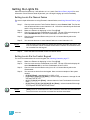
Setting Levels Via Channel Faders
For more in depth information on using Element’s channel faders, see Using Channel Faders, page
76.
Step 1:
Check to make sure the Fader Position Switch is set to Channel 1-40. The first two
rows of faders will then control channels 1-40. 1-20 will be controlled by the first bank
and 21-40 by the second bank.
Make sure Element is displaying in Live. Press [Live].
Check to make sure the Grandmaster is at 100%. The top of Element’s display will
show Grandmaster #% in red if the Grandmaster is below 100%.
Check to make sure the Blackout key is not lit. It is located directly above the
Grandmaster.
You can now raise one or more channel faders to control channels 1-40.
Step 2:
Step 3:
Step 4:
Step 5:
Note:
Use the Fader Position Switch to change the channels the faders will control. The
first 120 channels can be controlled via the faders. Channel 121 and above must
be controlled from the keypad.
Step 6:
Lower the faders as needed to fade out channel levels.
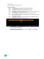
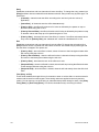
Setting Levels Via the Control Keypad
For more information about the control keypad, see Selecting Channels, page 77.
Step 1:
Step 2:
Step 3:
Step 4:
•
•
•
•
Note:
1
Quick Start
Make sure Element is displaying in Live. Press [Live].
Check to make sure the Grandmaster is at 100%. The top of Element’s display will
show Grandmaster #% in red if the Grandmaster is below 100%.
Check to make sure the Blackout key is not lit. It is located directly above the
Grandmaster.
You can now set levels from the keypad. Here are some examples of the syntax
needed:
[5] [Full] [Enter] - sets channel 5 to 100% or Full.
[1] [Thru] [1] [0] [At] [7] [5] [Enter] - selects a range of channels 1 through 10 and
sets their level to 75%.
[2] [+] [7] [At] [2] <0> [Enter] - selects channels 2 and 7 and sets their levels at
20%.
[5] [0] [Thru] [7] [0] [-] [6] [0] [At] [5] <0> [Enter] - selects channels 50 through
70, except 60, and sets their levels to 50%.
[Enter] must be used at the end of the command to terminate the command line.
Levels will not be set until the command line has been terminated.
9
Step 5:
•
•
•
•
•
To remove a channel’s level, you can either use the command [At] [Enter], or you can
use [Sneak] [Enter]. If you have not recorded any lighting looks yet, [At] [Enter]
removes the manual value and sets to out. This will provide a manual 0 for the
channel. If you store from this state, you will be storing a move to zero in the cue or
submaster you stored. [Sneak] [Enter] removes the manual level and sets to the
background state. If there is no cue or submaster in the background, the level will be
set to its home value, resulting in a null state.
[1] [0] [At] [Enter] - sets the level of channel 10 to 0%.
[Sneak] [Enter] - fades out all manual levels.
[5] [Sneak] [Enter] - fades out the manual level for channel 5.
[1] [Thru] [1] [0] [At] [Enter] - sets the levels for channels 1 through 10 to 0%.
[2] [0] [Thru] [2] [5] [Sneak] [Enter] - fades out the levels for channels 20 through
25.
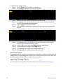
Recording a Lighting Look
Submasters and cues are two ways that you can record looks to be able to recall them. This quick
start will only cover recording submasters.
Recording a Submaster
For more information about submasters, see Storing and Using Submasters, page 87.
Step 1:
Step 2:
Note:
Step 3:
Step 4:
Set the channel levels that you want in your look using the channel faders and/or
keypad.
Switch the Fader Position Switch to Submaster mode.
If you have an Element 60 console, the third bank of faders are always in
submaster mode.
Press [Record] then the bump button of the submaster you wish to record. This
action will terminate the command line so there is no need to hit [Enter]. You can also
record a submaster using the following syntax, [Record] [Sub] [#] [Enter], in case
you don’t want to jump to submaster mode on the faders.
You can either leave that look up and build upon it or use [Sneak] [Enter] to fade out
the manual levels.
If you would like to record looks to be able to play them back using Element’s [Go] button, please
see Basic Cueing, page 98.
10
Element User Manual
Chapter 1
Element Overview
Inside this chapter you will find a general overview of your Element control console.
This chapter contains the following sections:
1
•
Console Geography. . . . . . . . . . . . . . . . . . . . . . . . . . . . . . . . .12
•
Control Keypad Layout . . . . . . . . . . . . . . . . . . . . . . . . . . . . . .13
•
Terminology . . . . . . . . . . . . . . . . . . . . . . . . . . . . . . . . . . . . . . .14
•
Cleaning Element. . . . . . . . . . . . . . . . . . . . . . . . . . . . . . . . . . .14
•
Outputting DMX . . . . . . . . . . . . . . . . . . . . . . . . . . . . . . . . . . . .15
•
Console Capacities . . . . . . . . . . . . . . . . . . . . . . . . . . . . . . . . .16
Element Overview
11
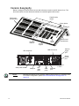
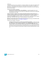
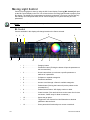
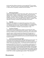
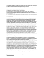
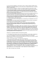
Console Geography
Below is a diagram of the Element console with references made to specific areas of use. The
terms and names for each area and interface are used throughout this manual.
Fader Position
Switch
Faders and
bump buttons
Power button
USB port
Playback
controls
Level
wheel
Control
keypad
Blackout and
Grandmaster
Remote
trigger
port
MIDI Out and In
IEC receptacle
Phone
remote
port
Hard power switch
Note:
12
VGA port
DVI
video
ports
DMX ports
1 and 2
USB
ports
Ethernet
port
Element can support up to 2 monitors, either 2 DVI monitors or 1 VGA and 1 DVI.
For monitor configuration, please See “External Monitor Arrangement” on
page 213.
Element User Manual
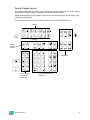
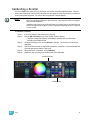
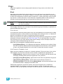
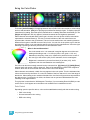
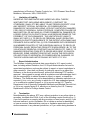
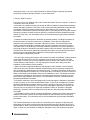
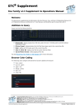
Control Keypad Layout
The control keypad area is divided into several sections including record targets, numeric keypad
with modifiers, display, softkeys, navigation, and special function controls.
Display and navigation keys are used for quick access to common displays, format, paging, and
navigation within displays.
The load button is located above the fader pair and is used to load the specified cue.
Display
ll
Softkeys
Special
function
controls
Navigation
Shift
Record targets
and related
commands
1
Element Overview
Numeric Keypad and
modifiers
13
Terminology
Pow e r Button
The power button on the front of the console is used to power up the Element console. A separate
power switch, located in the rear panel of the console, can be used to disconnect power from the
console’s internal components.
WARNING:
Before servicing the Element control console, you must switch off the
power from the rear of the console and disconnect the power cord
completely.
US B Ports
One USB port is provided on the front of the console to connect any USB storage device. Additional
USB ports on the rear panel of the console can be used to connect peripherals such as an
alphanumeric keyboard, pointing device, or touchscreen control for external monitors.
CAUTION:
It is not recommended that the USB ports be used for charging devices like cell
phones.
Level Wheel
Proportionally adjusts intensity for selected channels. It also provides scrolling and zoom functions
in various modes.
IEEE Ethernet 802.3 Ethernet Port
Ethernet port for connection to a network switch, network gateways, and accessory devices.
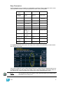
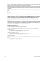
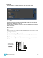
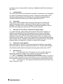
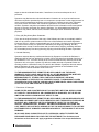
Littlites®
You may connect a Littlite to the side of your Element console.
Pinout for Littlite XLR 3-Pin Female Connector
2
1
Chassis Ground
2
Dimming Leg
3
+12 Vdc
1
3
Connect the Littlite
between pins 2 and 3.
Cleaning Element
Should the exterior of your Element require cleaning, you may gently wipe it with a dampened (not
dripping), non-abrasive paper towel or soft cloth.
If this does not clean the console sufficiently, you may apply some window cleaner (containing
ammonia is fine) to the cloth and repeat the process until clean.
14
Element User Manual
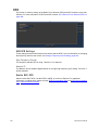
O u t p u t ti n g D M X
In order to output control levels from Element, you can either use the DMX ports on the back of the
console, or to output over a network, you may connect a Net3 gateway or Net2 node. If your device
receives Net3 or ETCNet2 directly, no gateway or node is required.
Element has two DMX ports. To output, connect one 5 pin XLR cable per port. The first port will
default to outputting the first universe of DMX, addresses 1-512, and the second port to the second
universe, outputting addresses 513-1024. See Local DMX, page 223 for information on
reconfiguring the DMX ports.
Nodes and gateways must be configured and given an IP address before they can function with
Element. This may require using NCE (Network Configuration Editor) or GCE (Gateway
Configuration Editor) and a Windows® PC to configure the gateways or nodes. The NCE or GCE
Software CD and related user manuals and setup guides were packaged with your gateway or
node. Use these materials to prepare them for use with Element.
For more information on Net3 gateways or Net2 nodes, see the product literature that accompanied
the hardware or download it from our website at www.etcconnect.com.
1
Element Overview
15
Console Capacities
Output Parameters
• 1,024 Outputs (DMX channels)
Channel Counts
• 250 or 500 Channels
Cues and Cue List
• Up to 10,000 cues
• 1 Active Playback
• 1 Cue List
Record Targets
• 1,000 Groups
• 1,000 x 4 Palettes (Intensity, Focus, Color and Beam)
• 1,000 Curves
• 1,000 Effects
• 1,000 Macros
Faders
• 1 Grandmaster with Blackout
• 1 Master Playback, with Go and Stop/Back
• 40 or 60 Faders with bump buttons
• a maximum of 300 configurable submasters
• 120 channel faders
16
Element User Manual
Chapter 2
System Basics
This chapter will discuss using the basic Element displays.
This chapter contains the following sections:
2
System Basics
•
The Central Information Area (CIA) . . . . . . . . . . . . . . . . . . . .18
•
Using Softkeys . . . . . . . . . . . . . . . . . . . . . . . . . . . . . . . . . . . . .19
•
Using the Browser . . . . . . . . . . . . . . . . . . . . . . . . . . . . . . . . . .20
•
Display Control and Navigation . . . . . . . . . . . . . . . . . . . . . . .21
•
Using [Format] . . . . . . . . . . . . . . . . . . . . . . . . . . . . . . . . . . . . .24
17
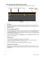
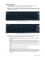
The Central Information Area (CIA)
The Central Information Area (CIA) is displayed on the lower portion of the screen.
Command Line
Command Line Prompt
Browser
Double arrows
CIA show/hide
CIA lock
(shown
unlocked)
Softkeys
Browser
The browser is the interface for numerous functions including saving a show, opening a show,
changing settings, viewing record target lists, opening displays and many other functions. Press
[Browser] to display.
Collapse/Expand the CIA
It is possible to collapse the CIA from view. You can collapse the CIA by pressing [Browser] or by
clicking the double arrow icon on the right side above the CIA. The CIA will collapse from view,
exposing a larger viewing area of whatever display is visible above the CIA. The double arrows will
move to the bottom of the screen.
To expand the CIA into view again, press [Browser] or click the double arrow at the bottom of the
screen. The CIA will reopen.
Lock the CIA
You can lock the CIA in place to prevent it from being collapsed.
To lock the CIA, click on the lock above the browser. The double arrow above the CIA will
disappear and the lock will “lock” the CIA to hold it in place.
To unlock the CIA, click the lock again and the double arrows will reappear.
Command Line Prompt
Directly above the command line, you will see red text that will prompt you for an action. The
prompts will change between different displays and actions, and are useful information to aid you in
programming.
18
Element User Manual
Using Softkeys
Some of the features and displays in Element are accessible from the softkeys, which are located
in the bottom right area of the CIA. Those softkeys correspond to buttons [S1] - [S6] and [More
SK].
Remember the use of the [Browser] button. This button offers softkeys that access the following
displays:
•
•
•
•
Effect Status
Show Control
Curves
Mirror
Each of these displays offers its own specific softkeys of relevance.
Context Sensitive Softkeys
Softkeys are context sensitive and will change depending on a number of factors including: the
active display, the current command line, the active record target, and so on. Element always
repaints the softkeys to coincide with your current action.
To get the full use of features on your Element system, be sure to familiarize yourself with the
softkeys that become available as you program your show.
Changing Softkey Pages
When there are more relative softkeys than the six available softkey buttons, the LED in the [More
SK] button will light. Press [More SK] to view the additional softkeys.
2
System Basics
19
Using the Browser
To use the browser, you must first draw focus to it by pressing the [Browser] key.
When focus is on the browser, the window border highlights in gold. The scroll lock LED illuminates
red and the paging keys will now control selection in the browser.
Menu arrows
Opened menu
Selection bar
Scroll bar
Sub menus
• Use the page arrow keys to move the selection bar up and down the list. You can also use the
level wheel to scroll through the list.
• When the bar highlights the desired menu, press [Page ] to open the menu.
• Continue pressing [Page ] to open submenus.
• Scroll to the item you wish to open using [Page ] or [Page ] and then press [Select]. You
may also click the item you wish to open and then press [Select]. You can also use the level
wheel to scroll in the browser.
• If you wish to close a submenu scroll to that item and press [Page ].
• To draw focus to the browser at any time, press the [Browser] key.
20
Element User Manual
Display Control and Navigation
Opening and Closing Displays
Displays can be opened and closed in different ways, depending on the display. Many displays are
accessible from Element’s keypad, while other displays are accessible from the browser and
softkeys. The blind displays of record targets (also called “lists”) can be quickly accessed by double
pressing the record target button, such as [Sub] [Sub] will display the submaster list.
From the hardkeys
Several displays are opened directly from buttons on Element’s keypad. Those displays are Live,
Blind, Patch, Setup, Park, Browser, and ML Control. You can open list views of any record target by
double-pressing the key for the desired record target
From the browser
Open and navigate the browser as described in Using the Browser, page 20. When you open a new
display (such as the cue list index or group list), it will open on the primary display. If the display
does not open to a monitor (such as setup or the browser) it will open in the CIA. Some displays are
available from the softkeys when the [Browser] button is pressed.
Again, any time you wish to return to the browser, simply press [Browser].
Closing Displays
To close any display:
• Press the [Browser] key again to open a different display.
• Press [Escape] to close the active display. The screen will return to live or blind.
• Press [Live] or [Blind] to replace the display with the live/blind view.
To close a display in the CIA, press the [Browser] key and the browser will reappear.
Swap Displays
When using two monitors, you can swap displays between monitors by pressing the [Swap] key.
Press it again to return to the original configuration.
2
System Basics
21
Scrolling within a Display
By default the page keys will advance/retreat a display by one page per press. However, to scroll
through displays you may press the [Scroll Lock] key on the keypad. The LED on the button
illuminates red when in scroll lock mode.
Scroll lock is a toggle state. When scroll lock is first pressed:
• [Page ] - scrolls table, spreadsheet and channel views down,
• [Page ] - scrolls table, spreadsheet and channel views up,
• [Page ] - scrolls table and spreadsheet views right,
• [Page ] - scrolls table and spreadsheet views left.
Expanding Displays
[Expand] allows a display to be viewed across multiple monitors.
To expand a display, such as live or patch, press [Expand]. To collapse an expanded view, press
[Expand] again.
[Data] Key
Pressing and holding [Data] allows you to view the values behind any referenced or marked data.
[Data] exposes the next lower reference level. So if you view a palette reference and press [Data],
the absolute data will be displayed instead.
[Data] can also be used to change the address views in patch. See “Using EDMX vs Port/Offset” on
page 49.
[Label] Key
Element allows for labeling of cues, channels, submasters, and more. Below are some examples of
labeling syntax:
Note:
You will need a mouse, keyboard, or touchscreen to create labels.
• [Cue] [6] [Label] <name> [Enter]
• [Group] [3] [Label] <name> [Enter]
• [Sub] [8] [Label] <name> [Enter]
If you press the label key for a target already labeled, this posts the current label to the command
line. To clear, press [Label] again. You can [Clear] to backspace one character at a time, or type to
append to the existing label.
[Recall From], [Copy To], {Replace With}, and {Move To}
[Recall From], [Copy To], {Replace With}, and {Move To} may be used to create and edit data.
See “Advanced Manual Control” on page 177.
22
Element User Manual
Using Flexichannel
Flexichannel (use of the [Flexi] key) allows you to view only channels meeting a certain criteria in
the live/blind display, therefore removing unwanted data from view. Flexichannel has several
available states which include allowing you to view:
• All channels
• All patched channels
• Manual channels
• All show channels (any channels that have data stored in a cue or submaster)
• Active channels (channels with intensity above zero or a move instruction)
• Selected channels
In flexi mode, any selected channels (including the last channel selection) are always included in
the view. Gaps in channel numbers are indicated by a vertical line between the channels where a
gap in numbering occurs.
To change flexi modes in the live/blind display, press [Flexi] to cycle through the views listed above.
When [Flexi] is held down, the softkeys change to represent all of the available flexi states. You can
select the desired flexi view from those keys.
[Next/Last] can be used to select the next or last channel in the current flexi mode.
[Thru] can be used to view only channels in the current flexi mode (except for selected channels
mode) as long as either the first or last channel in the [Thru] range is included in the current flexi
mode. To include channels not in the current flexi mode, [Thru] [Thru] can be used.
View Channels
You may select specific channels to appear in another flexichannel state called “View Channels”.
This state does not exist until you select channels to view. After view channels is activated, it will
appear in the rotation of flexichannel states when [Flexi] is pressed.
To select channels to view:
Step 1:
Step 2:
Step 3:
Select channels on the command line (do not press [Enter]).
Press and hold [Flexi].
Press {View Chans}. The “View Channels” flexi state will be created and the
channels you selected will be visible in it.
The channels you selected will be visible in this flexi state until you select other channels and press
{View Chans} again. At any time, you can access the last channels you defined for this state by
pressing [Flexi] until this state is visible.
To redefine the selected channels in the state, simply follow the steps above again.
2
System Basics
23
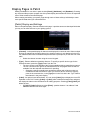
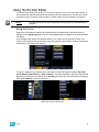
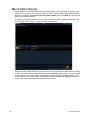
Using [Format]
Some displays have multiple formats. When the display is first opened, it opens in its default view.
The default view for Live/Blind is table view. Pressing [Format] will toggle between table, summary,
and, if in Blind, spreadsheet views.
Live and Blind share formatting. When you change from one format to another format, you are
always working with the same format until you change it. The exception to this is spreadsheet,
which is only available in blind. If you are working in blind spreadsheet, when you return to live you
will be working with the table or summary view, based on which one you were last using.
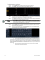
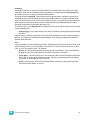
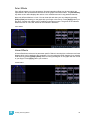
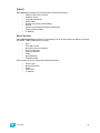
Table View
Table view is available in live or blind. If devices other than dimmers are patched, table view
displays the fixture type associated with channels and details about each channel’s category and
parameter levels.
In live, table view displays all active channel data being output from Element. In blind, it will display
all data for a single record target (cue, palette).
In the table view, a slight space is provided between fixture types, giving a clear delineation
between them. The name of the fixture type is displayed at the top of the section for that fixture.
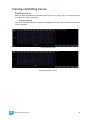
Parameter data
Fixture type
Live Table View
24
Element User Manual
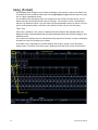
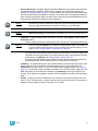
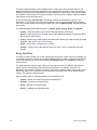
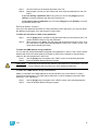
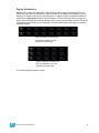
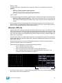
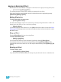
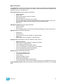
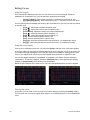
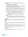
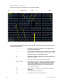
Summary View
The summary view displays the largest number of channels of any of the formats. Below you can
see channels 1-80 are shown. This format is best used to see large numbers of channels’ intensity
data or parameter category data. Individual non-intensity parameters are not visible in this view.
Channel numbers
Unpatched channel
Intensity data
F, C, B data
Deleted channel
Z o o m i ng D i s p l a y s
You may zoom the table and summary view to display more or less channels. To do this, press and
hold the [Format] button and scroll the Level Wheel to alter the number of channels visible.
Scrolling the wheel up zooms in. Scrolling the wheel down zooms out. Zooming this display when
it is in 100 channel mode is not supported. A mouse can also be used to control zooming by holding
down the left button while using the scroll wheel.
2
System Basics
25
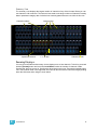
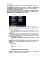
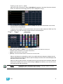
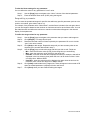
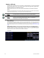
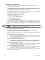
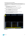
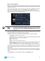
Spreadsheet (Blind Only)
Spreadsheet format is available only in blind mode. It is useful for viewing and editing channel data
and trends for multiple cues, submasters, or palettes at one time. Cues and other record targets are
displayed on the vertical axis and channel data is visible on the horizontal axis. See “Recording and
Editing Cues from Blind” on page 113.
To toggle between viewing just the intensity information and other parameters, press [Shift] &
[Format].
Cue numbers
26
Channel number
Parameters
Element User Manual
Chapter 3
Managing Show Files
This chapter explains how to create, open, and save your show files. Each of these operations are
accomplished through the browser area.
This chapter contains the following sections:
3
•
Create a New Show File. . . . . . . . . . . . . . . . . . . . . . . . . . . . . .28
•
Open an Existing Show File . . . . . . . . . . . . . . . . . . . . . . . . . .28
•
Merging Show Files . . . . . . . . . . . . . . . . . . . . . . . . . . . . . . . . .31
•
Printing a Show File. . . . . . . . . . . . . . . . . . . . . . . . . . . . . . . . .32
•
Saving the Current Show File . . . . . . . . . . . . . . . . . . . . . . . . .34
•
Using Quick Save. . . . . . . . . . . . . . . . . . . . . . . . . . . . . . . . . . .34
•
Using Save As . . . . . . . . . . . . . . . . . . . . . . . . . . . . . . . . . . . . .34
•
Importing Show Files. . . . . . . . . . . . . . . . . . . . . . . . . . . . . . . .35
•
Exporting a Show File . . . . . . . . . . . . . . . . . . . . . . . . . . . . . . .35
•
Deleting a File. . . . . . . . . . . . . . . . . . . . . . . . . . . . . . . . . . . . . .35
Managing Show Files
27
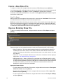
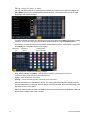
Create a New Show File
To create a new show file, navigate within the browser to: File> New> and press [Select].
You will be prompted for confirmation that you want to reset the system. Any unsaved show data will
be lost. Press [Select] or click {OK} to confirm or {Cancel} to discontinue the operation.
In Element, a new show file defaults to a 1 to 1 patch. Clicking {Patch 1to1} will deselect the option
and result in a blank patch.
Show File Names
Names of show files may appear in the browser list in normal text or in bold text. Files in normal
text indicate that there is only one show file stored by that name.
Bold show names indicate that there are several versions of the show file stored under that name,
the bold one being the most recent. To access the most recent show file, simply select the bold
name. You may right arrow [] from the bold name to expand a list of previous versions beneath it
in the browser. Select the desired show from the expanded list.
Open an Existing Show File
To open an existing Element show file, navigate within the browser to: File> Open> and press
[Select].
Element provides you with multiple locations to retrieve an Element show file (.esf) including:
• Show File Archive - This is the default storage location for show files when a show file is
created and saved. Older versions of the show file will be listed under the most current
version. This allows you the ability to open the latest version or an earlier version of a show
file if desired.
• File server - if one is connected. When there is no file server connected, it will not display in
the browser. See “Network Drives” on page 221.
• USB storage device - When a USB device is connected and an Element show file (.esf) is
available on the device, you will notice the USB device’s name and drive letter are displayed
in white text and expandable. When the USB device is connected and no Element show file
is loaded on the device, you will notice the USB device’s name and drive letter will be
displayed in a grey color and is not selectable.
Open the desired location:
• To open a show file from the Show File Archive, navigate within the browser to: File> Open>
Show File Archive and press [Select].
• To open a show file from the file server, navigate within the browser to: File > Open> File
Server> and press [Select].
• To open a show file from a USB device, navigate within the browser to: File> Open> USB (E:)
and press [Select].
28
Element User Manual
Select the specific show file
• Navigate within the specified storage location and select the show file you wish to open, press
[Select].
• If the selected show has multiple time stamps, navigate to the desired revision and press
[Select].
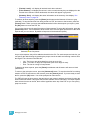
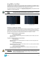
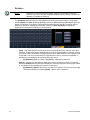
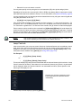
This will open the partial show loading screen in the CIA.
From this screen you can select which components of the show file you wish to load. The buttons
at the center of the CIA represent all of the show components that you can choose to load. By
default all components are selected (gray) and will be loaded. To withhold any show components
from loading, simply deselect them in the CIA by clicking the respective button.
Note:
You will need a mouse, keyboard, or touchscreen to deselect options.
CAUTION:
On a partial show open, if any record targets are not opened, any existing data of
that type will be cleared from the console.To merge show data, merge should be
used. See “Merging Show Files” on page 31.
To reselect all show components, click the {Reset} button and all buttons will return to gray
(selected). To stop the show load process, click the {Cancel} button.
When you have selected or deselected all of the show components you require, press [Select] or
click {OK}.
Element loads the selected show to the console.
3
Managing Show Files
29
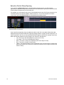
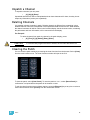
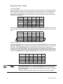
Selective Partial Show Opening
If you select the {Advanced} button in the partial show opening screen, you will have the
opportunity to load partial components from the show file and be able to specify the desired location
of those partial components in the new show file.
For example, you could specify only cues 5-10 and load them as cues 20-25 in the new show. You
could also specify only specific palettes, effects, and so on. To see the complete list of show
components, press the {Advanced} key in the partial show loading screen.
Selected Show Components
As you specify components, they are added to a table in the CIA. In the table, fields with a dark
background may be edited, fields with a light gray background do not apply to that component. For
each component in the list, you can specify the desired range by clicking in the proper area in the
table and entering numbers from the keypad. The columns in the table are:
•
•
•
•
•
30
List - The list you are taking data from (such as a cue list).
List Target - The list you are adding the data to.
Start - The first in a range of components (such as a range of cues).
End - The last in a range of components.
Target - The desired location of the components in the new show file (for ranges, this
will be the location in the new show of the first component in the range, the others will
follow in order).
Element User Manual
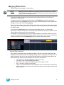
Merging Show Files
Element supports the merging of .esf show files.
Note:
Merging show files is different from opening show files. When you do a partial
open of show components, untouched record targets are cleared. When you do a
merge, those record targets remain.
You have the option of merging .esf show files from the Show File Archive, a File Server (if
connected), or a USB device.
To merge a show file, navigate within the Browser to: File> Merge>. Navigate to the desired
storage location and press [Select]. When using merge, Element displays only the available files.
Navigate to the specific file and press [Select].
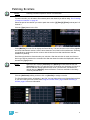
This will open the merge screen in the CIA. From this screen you can choose which aspects of the
show file you want to merge. By default all aspects are unselected (black). Selected show aspects
will appear in gray.
If you select the {Advanced} button in the merge show loading screen, you will have the
opportunity to load partial components from the show file and be able to specify the desired location
of those partial components in the current show file.
For example, you could specify only cues 5-10 and load them as cues 20-25 in the cue list in the
new show. You could also specify only specific palettes, effects, and so on. To see the complete list
of show components, press the {Advanced} key in the merge show loading screen.
Selected Show Components
As you specify components, they are added to a table in the CIA. In the table, fields with a dark
background may be edited, fields with a light gray background do not apply to that component. For
each component in the list, you can specify the desired range by pressing the proper area in the
table and entering numbers from the keypad. The columns in the table are:
•
•
•
•
•
3
List - The list you are taking data from (such as a cue list).
List Target - The list you are adding the data to.
Start - The first in a range of components (such as a range of cues).
End - The last in a range of components.
Target - The desired location of the components in the new show file (for ranges, this
will be the location in the new show of the first component in the range, the others will
follow in order).
Managing Show Files
31
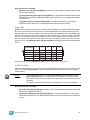
To merge only partial components:
Step 1:
Step 2:
Step 3:
Step 4:
Step 5:
Step 6:
From the browser, navigate to the desired show file (see Open the desired location:,
page 28).
When the merge show load screen appears, press the {Advanced} button. The
partial components selection screen will appear in the CIA.
Select the show components that you wish to merge by pressing on their respective
buttons on the left side of the CIA. The components will appear in the list to the right
as you select them.
Press any fields for which you want to enter specific numbers. The field (if editable)
will highlight in gold.
Enter the numbers using the keypad to specify the desired cues/groups/effects and so
on.
Press {OK} to load the components to the current show.
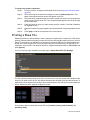
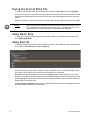
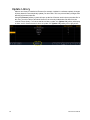
Printing a Show File
Element provides you with the ability to save a show file or aspects from a show file to a PDF file for
printing. Element has three locations to save the PDF files including the Show File Archive, the File
Server (if connected), or a USB device (if connected). Saving the PDF file to a USB storage device,
allows you to then print the PDF from a personal computer. Printing directly from Element is not
supported. To save a PDF of an Element show file, navigate within the browser to: File> Print> and
press [Select].
You can select the page orientation and paper type in Setup>Desk>PDF File Settings.
This will open the printing screen in the CIA. From this screen you can choose which aspects of the
show file you want to save to PDF. By default all aspects are selected (gray) and will be saved. To
withhold any show aspects from printing, simply deselect them in the CIA by clicking the respective
button. Deselected show aspects will appear in black.
Three buttons that will impact the overall PDF are {Tracked Levels}, {Color Printout}, and
{Summary View}.
32
Element User Manual
• {Tracked Levels} - will display all tracked levels when selected.
• {Color Printout} - will display the values in color to match the way they are displayed on the
console when selected. When deselected, the values will appear in grayscale.
• {Summary View} - will display the same information as the summary view display. See
“Summary View” on page 25.
To reselect all show aspects, press the {Reset} touchbutton and all buttons will return to gray
(selected). To stop the show file from being saved to a PDF and return to the browser, press the
{Cancel} button. When you have selected/deselected all of the show aspects you require, press
the {Ok} button to create the PDF file.
You can also choose to print specific portions of show aspects. To select this information, press the
{Advanced} button. The touchbuttons at the center of the CIA will again represent all of the show
aspects that you can choose. By default all aspects will be deselected (black).
Selected Show Component
As you select aspects, they will be added to the table in the CIA. For each component in the list, you
can specify the desired range by pressing the proper area in the table and entering numbers from
the keypad. The columns in the table are:
•
•
•
List - The list you are taking data from (such as a cue list).
Start - The first in a range of components (such as a range of cues).
End - The last in a range of components.
To deselect all show aspects, press the {Reset} touchbutton and all buttons will return to black
(deselected).
To return to the main print screen, press the {Advanced} button. To stop the show file from being
saved to a PDF file and return to the browser, press the {Cancel} button. If you are ready to save
the file, press the {Ok} button. You will be prompted to name the file.
The PDF will have the show name, date and time it was created, and date and times for when the
show file was last saved. It also gives the Element software version information. If multiple aspects
were selected to save to the file, there will be hyperlinks at the top of the PDF so you can quickly
jump to a section.
3
Managing Show Files
33
Saving the Current Show File
To save the current show data, navigate within the browser to: File> Save> and press [Select].
The Show File Archive is the default storage location for show files when they are saved. The new
time stamp located beneath the show file name on the CIA indicates that the show file has been
saved.
All previous saves are stored in the Show File Archive with the time stamp following the file name.
Note:
When saving a show file for the first time, Element will provide the name “Show
File” and will attach a time/date stamp to the name. To change the name, use a
mouse and the on-screen keyboard, or an attached USB keyboard.
Using Quick Save
To save the current show data to the hard drive without having to navigate to the browser, hold
down [Shift] & [Update].
Using Save As
To save an existing Element show file to a different location or with a different name, navigate within
the browser to: File> Save As> and press [Select].
Element provides you with three locations to save an Element show file (.esf) including the Show
File Archive, the File Server (if connected) or a USB device (if connected).
Navigate to the desired storage location and press [Select]. When using “Save As” to save the
show file to a specific location, the alphanumeric keypad will display on the CIA. Name the show file
and press [Enter]. The show file will be saved in the specified location with the show file name you
entered with a time stamp suffix.
Pressing [Label] or [Delete] on the console, or DELETE on an alphanumeric keyboard will remove
the default show label when doing a Save As.
34
Element User Manual
Importing Show Files
Element supports the import of standard USITT ASCII, and Light Wright show files.
Note:
Element supports ASCII show file import from a number of other control consoles,
including the Obsession, Expression, Emphasis, and Congo product lines, as well
as the Strand 300 Series. Please note that all show files must be saved in an
ASCII format prior to importing them into Element.
CAUTION:
The way data is stored and used is often different between different consoles.
Imported data may not playback exactly the same between consoles.
You have the option of importing standard USITT ASCII (.asc) or Light Wright data (.txt or .asc) from
the Show File Archive, a File Server (if connected), or a USB device.
To import a show file, navigate within the Browser to: File> Import> (Type of file to import) and
press [Select]. If you are importing an USITT ASCII file, you will have two options, Import as Library
Fixtures or Import As Custom Fixtures. Import as Library Fixtures will allow Element to try to match
the fixtures in the file with fixtures in the Element library. Import as Custom Fixtures will bring the
fixtures in as they are in the file. It is recommended to use Import as Custom Fixtures.
Navigate to the desired storage location and press [Select]. When using import, Element displays
only the available files. Navigate to the specific file and press [Select].
Exporting a Show File
Export your Element show file to a standard USITT ASCII, .csv, Focus Track, or Fast Focus Pro
show file using the export feature.
To export your Element show file in ASCII format, navigate within the browser to: File>
Export>USITT ASCII and press [Select]
You have the option of exporting your show file in ASCII format to the Show File Archive, to a File
Server (if connected), or to a USB device.
Navigate to the desired storage location and press [Select]. The alphanumeric keypad will display
on the CIA. Name the show file and press [Enter]. The file will be saved in the specified location
with the file name you entered with a “.asc” file extension.
You can export Element show files as a .csv format by navigating within the browser to: File>
Export> CSV and select the location for the export, the Show File Archive, a File Server (if
connected), or to a USB device.
Files can also be exported as in a Focus Track or Fast Focus Pro format by going to File> Export>
Fast Focus Pro or Focus Track and select the location for the export, the Show File Archive, a File
Server (if connected), or to a USB device.
Deleting a File
Element provides you with the ability to delete show files from the Show File Archive and the File
Server from within the browser.
To Delete a Show File
Navigate within the browser to: File> Open and press [Select]. Navigate to the desired show file
and press [Delete]. Press [Enter] to confirm or any other key to abort the deletion process.
3
Managing Show Files
35
36
Element User Manual
Chapter 4
Setup
This chapter discusses Element’s system settings that you can change to meet your preferences.
This chapter contains the following sections:
4
Setup
•
Opening Setup . . . . . . . . . . . . . . . . . . . . . . . . . . . . . . . . . . . . .38
•
Show . . . . . . . . . . . . . . . . . . . . . . . . . . . . . . . . . . . . . . . . . . . . .38
•
Desk . . . . . . . . . . . . . . . . . . . . . . . . . . . . . . . . . . . . . . . . . . . . .40
37
Opening Setup
There are two ways to open the setup screen. You can either press [Setup] or press [Browser] and
scroll down to {Setup}.
The CIA will display the setup screen and the softkeys will change. Element will default to
displaying show settings, however if you change the view, Element will remember the view you
were in when you return to setup.
The setup displays are:
• Show
• Desk
Note:
To select buttons in the show and desk displays, you can either use a mouse or
the arrow keys on Element along with the {Properties} softkey. {Properties} will
allow you to scroll through the fields and pressing [Select] will choose a field.
Pressing [Select] again will toggle options, such as ‘Enabled’ and ‘Disabled”.
Some fields require data from the keypad and then [Enter]. Selecting
{Properties} again will return the scroll ability to the buttons on the left of the CIA.
Show
When you select the {Show} softkey, the CIA will display the following buttons:
• Show Settings
• Cue Settings
• Show Control
Show Settings
Click {Show Settings} to enter this category.
Seven fields will be available to you: {Num of Channels}, {Dim. Dbl. Offset}, {Allow HS Fades},
{Fader Mode}, {Mark Time}, {Startup Macro}, and {Shutdown Macro}.
{Num of Channels}
You may use this field to set the number of channels in your Element to the number of channels in
your system, up to either 250 or 500 depending on the channel count for your Element. Enter the
number of channels for your system using the keypad. This is useful for controlling paging. This
entry must be confirmed with the [Enter] key.
{Dim. Dbl. Offset}
This allows you to set the address offset for dimmer doubling. The default for this is 20000, to match
the Net2 standard offset, including Sensor+ software.
{Allow HS Fades}
Hue and saturation (HS) color data normally fades in native space. Enabling {Allow HS Fades} will
make HS data fade in HS space.
{Fader Mode}
This field allows you to set the fader mode for the cue list. Options toggle between Proportional
Master, Intensity Master, and Manual Master. For more information on Proportional and Intensity
Masters, See “Proportional vs. Intensity Master” on page 89.For information on Manual Master,
See “Manual Master Option” on page 131.
{Mark Time}
This field allows you to set the time that non-intensity mark instructions will use. When {Mark Time}
is disabled, which is the default, mark instructions will use cue timing.
38
Element User Manual
{Startup Macro}
This field allows you to set up a startup macro that will trigger after the console initialization has
completed.
{Shutdown Macro}
This field allows you to set up a shutdown macro that will trigger at power off, not when exiting the
application.
{Cue Settings}
Click {Cue Settings} to enter this category.
You will be able to set the cue default times for intensity up and down.
{Show Control}
This section allows you to adjust settings for MIDI show control, time code (MIDI or SMPTE),
analog, and serial functions
{SMPTE Time Code Rx}
This touchbutton is used to toggle SMPTE time code between “Enabled” and “Disabled”, thereby
controlling whether Element can receive SMPTE time code. Choosing “Disabled” will disable all
timecode lists that have a SMPTE source. The default for this setting is “Enabled”.
{MIDI Time Code Rx}
As above, but for MIDI instead of SMPTE. The default for this setting is “Enabled”.
{Resync Frames}
This touchbutton allows you to configure how many frames need to be synced before timecode
starts running. Frames can be from 1-30. Default is 2 frames.
{MSC Receive}
This touchbutton toggles the setting for receiving MIDI Show Control from an external source
between “Enabled” and “Disabled”. The default setting is “Disabled”.
{MSC Receive Channel}
Also known as “Device ID” this setting allows you to establish the device ID from which Element will
receive MIDI show control information. Only MSC data with the correct device ID will be received.
A device ID can be from 0-126, or if set to 127 Element will receive MSC data from all IDs (All Call).
For example:
• {MSC Receive Channel} [5] [0] [Enter]
{ACN - MIDI Rx ID(s)}
This setting allows you to specify the MIDI Show Control data that Element will receive when
transmitted over the Advanced Control Network (ACN). When set, Element will receive MSC data
from any gateway that has its “MIDI In Stream ID” set to the same number. ACN_MIDI Receive ID
can be from 1-32. ID ranges may be used. For example:
• {ACN_MIDI Receive ID} [2] [5] [Enter]
{MSC Transmit}
This touchbutton toggles the setting for transmitting MIDI Show Control data between “Enabled”
and “Disabled”. The default setting is “Disabled”.
{MSC Transmit Channel}
Also know as “Device ID” this setting allows you to establish the device ID with which Element will
transmit MIDI show control information. A device ID can be from 0-126. For example:
• {MSC Transmit Channel} [5] [0] [Enter]
4
Setup
39
{ACN - MIDI Tx ID}
This setting allows you to specify the ID number of MIDI Show Control data that Element transmits
over an Advanced Control Network (ACN). When set, Element will transmit MSC data to any
gateway that has its “MIDI Out Stream ID” set to the same number. ACN_MIDI Transmit ID can be
from 1-32. ID ranges may be used.
• {ACN_MIDI Transmit ID} [2] [5] [Enter]
{Analog Inputs}
This touchbutton toggles the setting for receiving analog inputs between “Enabled” and “Disabled”.
Default is “Enabled”.
{Relay Outputs}
This touchbutton toggles the setting for allowing Element to trigger external relays. Options are
“Enabled” or “Disabled”. The default is “Enabled”.
{Serial Enable}
This touchbutton toggles the ability to receive serial commands. Options are “Enabled” or
“Disabled”. The default is “Enabled”.
{Serial Group Ids}
This touchbutton is for setting up which serial group IDs the Element will listen to. Serial Group IDs
are from 1-32. Element can be set to listen to multiple group IDs.
• {Serial Group Ids} [1] [+] [5] [Enter]
Desk
When you select the {Desk} softkey, the CIA will display the following buttons:
• Record Defaults
• Manual Control
• Face Panel
• Face Panel Keypad
• Displays
• PDF File Settings
• Brightness Settings
• RFR Settings
• Trackball Settings
{Record Defaults}
This screen enables you to change general record defaults.
Auto Playback
When enabled, this feature automatically plays back cues as they are stored and releases manual
control. This field is a toggle state between “Enabled” and “Disabled”. When auto playback is
“Disabled”, all manual levels are maintained and cues must be loaded and executed on the split
fader. The default is “Enabled”.
Track
This field allows you to switch between tracking and cue only modes (see Tracking vs. Cue Only,
page 206). The default is “Tracking”.
40
Element User Manual
Record Confirm
This setting allows you to enable or disable the confirm action when storing over a previously
recorded target. The default is “Enabled”.
Delete Confirm
This field allows you to enable or disable a required confirmation before any delete command is
executed. The default is “Enabled”.
{Manual Control}
This desk setting button gives you access to Element’s manual control settings.
Manual Time
In this section you may change the default times for manual changes to occur in live. Times can be
set for Intensity Up and Intensity Down.
Manual Control
This section allows you to specify the values for certain buttons and settings used in manual
control. To change any value, click the appropriate button in the CIA and use the keypad to enter a
new value.
Preserve Blind Cue - This enables the console to recall the last selected cue in blind when
you return to blind. The default is disabled.
Level - This sets the default for Level (which is accessed in Element by double pressing
[At]). Any value between 0-100 may be entered. The default is 100.
Plus% - This sets the level for the +% (which is accessed in Element by pressing [Shift] &
[+]), which will increase the selected channel by the set percentage. Any value between 0100 may be entered. The default is 10%.
Minus% - This sets the level for -% (which is accessed by pressing [Shift] & [-]), which will
decrease the selected channel by the set percentage. Any value between 0-100 may be
entered. The default is 10%.
Rem Dim Level - This allows you to set the level for all Remainder Dim commands. The
default is 0.
Default Times
In this section you may change the default times for sneak commands, back time, and go to cue
time. The default for these is 5 seconds, except for back time, which uses a default of 1 second.
{Face Panel}
In this section you may change the sounds settings as well as adjusting the increment and
acceleration effect of the level wheel.
{Face Panel Keypad}
This screen allows you to adjust the auto repeat settings (delay and speed) for the facepanel
keypad as well as enable/disable the blackout and Grandmaster functions for your Element.
{Displays}
This desk setting button gives you access to the Element display settings.
High Contrast Display
This button toggles the setting between “Enabled” and “Disabled”. When enabled, high-contrast
brightens the cue numbers and channel numbers in displays and also brightens the magenta used
to show tracked values.
The default setting for this is “Disabled”.
4
Setup
41
Show Reference Label
This button toggles the setting between “Enabled” and “Disabled”. When enabled, referenced
record targets (such as palettes) with labels will have their labels displayed in the live/blind display
rather than their target type and number. [Shift] & [Label] can be used to toggle between views.
The default setting for this is “Disabled”.
Group Chans By 5
You can turn off/on the grouping of channels in groups of 5 in the live summary view from this field.
The default for this setting is “Enabled.
100 Channel Display
This setting can be used to display 100 channels at a time in the live summary view. The default for
this setting is “Disabled.”
Cmd Line on PSD
This setting can be used to display an optional command line on the Playback Status Display. The
default for this setting is “Disabled”.
PSD Time Countdown
In the Playback Status Display (PSD), holding down [Time], while a cue is fading, will display the
cue category times counting down in the cue list display area. The default action is to show the total
time not the countdown. When the {PSD Time Countdown} is enabled, the cue category times will
countdown as a cue is fading. To see the total time, hold down the [Time] key. {PSD Time
Countdown} is “disabled” by default.
{PDF File Settings}
This screen allows you to select the orientation and paper type for PDF files.
{Brightness Settings}
This screen allows you to adjust the brightness of attached desk lamps. The {Desk Lamp} fader
has a range of 0% (dimmest level) to 100% (brightest level).
{RFR Settings}
This screen is for allowing RFR connections. The default setting is “Enabled”.
42
Element User Manual
{Trackball Settings}
This screen allows you to make adjustments to a trackball.
{Trackball Tick Freq.}
This fader adjusts the trackball tick frequency. The default is 200 ticks.
{Trackball Acc. Fctr}
This fader adjusts the trackball acceleration factor. The default is 800 zip.
{Swap Pan/Tilt}
This touchbutton swaps the directions for Pan and Tilt. The default for Pan and Tilt is X and Y,
respectively. When this button is enabled, Pan and Tilt will be Y and X.
{Reverse Pan}
This touchbutton reverses the direction of Pan.
{Reverse Tilt}
This touchbutton reverses the direction of Tilt.
{Reset}
This button resets all five trackball settings back to their default.
4
Setup
43
44
Element User Manual
Chapter 5
Patch
The Patch is used to associate a channel with an address. Once a channel is patched to an
address, and the output is connected to a device (for example a dimmer, moving light, or
accessory), the channel will then control that device.
This chapter contains the following sections:
5
Patch
•
About Patch . . . . . . . . . . . . . . . . . . . . . . . . . . . . . . . . . . . . . . .46
•
Patching Conventional Fixtures . . . . . . . . . . . . . . . . . . . . . . .47
•
Patching Scrollers . . . . . . . . . . . . . . . . . . . . . . . . . . . . . . . . . .51
•
Patching Moving Lights, LEDs, and Accessories. . . . . . . . .52
•
Display Pages in Patch . . . . . . . . . . . . . . . . . . . . . . . . . . . . . .54
•
Using the Scroller Editor. . . . . . . . . . . . . . . . . . . . . . . . . . . . .59
•
Calibrating a Scroller. . . . . . . . . . . . . . . . . . . . . . . . . . . . . . . .63
•
Deleting Channels . . . . . . . . . . . . . . . . . . . . . . . . . . . . . . . . . .65
•
Clearing the Patch . . . . . . . . . . . . . . . . . . . . . . . . . . . . . . . . . .65
•
Update Library . . . . . . . . . . . . . . . . . . . . . . . . . . . . . . . . . . . . .66
•
Fixture Editor . . . . . . . . . . . . . . . . . . . . . . . . . . . . . . . . . . . . . .67
45
About Patch
Element treats fixtures and channels as one and the same, meaning each fixture is assigned a
single control channel number. Individual parameters of that fixture, such as intensity, pan, tilt,
zoom, or iris are also associated with that same channel number but as additional lines of channel
information.
You are required to enter only the simplest data to patch a device and begin programming your
show, such as the channel number, the device type (if needed), and address. When you provide
more information in the patch, you will have more detailed control and improved function during
operation.
One or more devices may be patched to a single channel. For example you may want to patch a
group of dimmers to the same channel. In addition you may patch multiple devices to the same
channel for building a compound or accessorized fixtures. For example a Source Four® with a color
scroller and a gobo changer may be patched to a single channel. This is referred to as a compound
channel.
When you open a new show file, Element creates a 1-to-1 patch. This means that the patch will
automatically have channel 1 patched to address 1, channel 2 to address 2, and so on up to the
maximum channel count of your console.
Selected to create a 1-to-1 Patch
Will not create a 1-to-1 Patch
Depending on your situation, you may need to create a custom patch, which associates certain
addresses with certain channels.
46
Element User Manual
Patching Conventional Fixtures
For patching fixtures, there are two different patch modes: patch by address and patch by channel.
Element defaults to patch by address mode. Pressing [Format] while in the patch display will toggle
the mode between patch by address and patch by channel.
Note:
When working with conventional devices, you can patch in either mode easily.
When working with compound channels or multiple parameter devices, it is
recommended to work in patch by channel.
Patching By Address
Patch By Address
[2] [0] [At] [1] [Enter] patches address 20 to channel 1. Pressing [At] will post channel to the
command line while patching by address.
Additional examples of patch by address:
• [5] [At] [1][0][0] [Enter] - patches address 5 to channel 100.
• [2][0][3] [At] [1][2] [Enter] - patches address 203 to channel 12.
Note:
An address can not be assigned to multiple channels, but a channel can have
multiple addresses assigned to it.
Note:
If, at any point, you try to patch an address that is already in use, Element will post
an advisory to indicate this, preventing you from duplicating addresses in your
patch.
Status in the Patch Display
The first column in the patch display will advise you when a channel requires your attention.
“!” is displayed next to a channel number when there is a RDM or CEM+ ACN error.
5
Patch
47
Patching By Channel
Pressing [Format] while in the patch display will toggle the mode between patch by address and
patch by channel.
Patch By Channel
In patch by channel mode, [2] [0] [At] [1] [Enter] patches channel 20 to address 1. Pressing [At]
will post address to the command line while patching by channel.
Additional examples of patch by address:
• [5] [At] [1][0][0] [Enter] - patches channel 5 to address 100.
• [2][0][3] [At] [1][2] [Enter] - patches channel 203 to address 12.
R a n g e P a tc h i n g
Range patching using the [Thru] key allows you to quickly patch a group of channels.
[1][Thru][2][0] [At] [1] [0] [Enter] patches channels 1 through 20 to addresses 10 through 29.
You can also use the [+] and [-] keys. [1] [+] [4] [+] [8] [At] [1] [Enter] patches channel 1 to
address 1, channel 4 to 2, and channel 8 to 3.
Note:
Range patching only works with channels. If you try to range patch addresses,
parts for the channel will be created. See “Creating a compound channel” on
page 49.
Labeling
To label a channel or address, press the [Label] key with the channel or address selected on the
command line. You can use the virtual alphanumeric keyboard or an external keyboard to enter the
desired label text.
[At] [Next]
[At] [Next] [Enter] finds the next available address range large enough to accomodate the
selected device.
Examples of [At] [Next]:
• [At] [2] [/] [Next] [Enter] - finds the next available address range on universe 2.
• [At] [7] [7] [7] [Next] [Enter] - finds the next available address after 777.
• [At] [/] [9] [Enter] - patches address 9 on the same universe that was last used.
48
Element User Manual
Using EDMX vs Port/Offset
Port/offset refers to the DMX universe or port and the offset of the address. For example, since a
single DMX cable can transmit 512 addresses (known as a “universe”), the port/offset for address
515 would look like 2/3 because address 515 is the 3rd address of universe 2.
An example of patching by port/offset view is [2][/][1][0] [At] [2][0] [Enter], which patches universe
2 address 10, or 522, to channel 20.
Note:
As it is possible to patch by either address or port/offset, pressing the [Data] key
will toggle the display to show the alternate output information.
EDMX View
Port/Offset View
Creating a compound channel
A compound channel consists of any channel that controls more than one device. It can consist of
mutliple dimmers patched to the same channel or accessories patched to a channel (such as a
fixture with a color scroller, a fixture with a gobo wheel, and so on). By default, Element will add a
part if you are trying to patch to a channel that has already been assigned an address.
To patch a compound channel in address format:
•
[5] [1] [3] [At] [8] [Enter]
Assuming channel 8 was previously patched to an address, this will create a part 2 and
address it at 513.
To patch a compound channel in channel format:
•
[9] [At] [5] [4] [0]
Assuming that channel 9 is already patched to an address, this will create a part 2 and
address it at 540.
•
[8] [Part] [2] [At] [5] [1] [3]
This will create a part 2 for channel 8 and address it at 513. If you wish to patch by address
while in the channel view, press:
•
[Address] [5] [1] [3] [At] [8] [Enter]
This will perform the same action as the previous example, assuming channel 8 was
previously patched to an address.
CAUTION:
5
Patch
It is recommended that you do not patch more than one multiple parameter device
(such as moving lights) to the same channel. Doing so can cause extreme
difficulty in controlling the devices.
49
Replace
By default, if you patch an address to a channel that is already patched, Element will create a new
part for the new address. If you want to replace the current address with the new, use {Replace}:
•
50
[n] {Replace} [n] [Enter] - replaces the address in part 1 of the selected channel.
Element User Manual
Patching Scrollers
Note:
Patching a scroller requires a mouse or touchscreen.
To patch a scroller, you will want to first create a part to the channel you will be using. See “Creating
a compound channel” on page 49.
Select the part of the channel you wish to patch the scroller. [3] [Part] [2] [Enter] selects part 2 of
channel 3.
Click the {Type} button in the CIA.
Press {Manfctr} from the CIA to display the fixture library. The two columns on the left are pagable
and show manufacturer names. Use the arrow buttons to scroll the list of manufacturers. Selecting
a manufacturer repaints the device columns with all devices from that manufacturer that are
available for patching.
Scroll through the device list and make your selection. After the selection is made, the fixture or
device type will be placed on the command line after the channel number and displayed in the box
beneath the {Type} button.
Note:
Notice the two softkeys {Favorites} and {Manfctr} located beneath the CIA.
{Favorites} provides you with the option of showing only the library of fixtures or
devices that are already patched in the show, your favorites, and Element’s
default devices. {Manfctr} shows all fixtures or devices available in the library
sorted by manufacturer.
Click the {Attributes} softkey, and then click on {Scroller} to assign a scroller.
The Scroller/Wheel picker will display in the CIA. You can either select one of the default scrollers
or you can create your own scroller. See Using the Scroller Editor, page 59 and Calibrating a
Scroller, page 63 for more information.
5
Patch
51
Patching Moving Lights, LEDs, and Accessories
The process of patching moving lights requires more detail than patching a dimmer. Specific
information is required for more advanced control of the features offered by moving lights.
It is recommended that when patching moving lights, LEDs, and accessories that you work in patch
by channel mode.
Note:
Patching moving lights, LEDs, and accessories require a mouse or touchscreen.
After you have entered the channel number, click {Type}. You will then select a device type from the
fixture library.
Press {Manfctr} from the CIA to display the fixture library. The two columns on the left are pagable
and show manufacturer names. Use the arrow buttons to scroll the list of manufacturers. Selecting
a manufacturer repaints the device columns with all devices from that manufacturer that are
available for patching.
Scroll through the device list and make your selection. After the selection is made, the fixture or
device type will be placed on the command line after the channel number and displayed in the box
beneath the {Type} button.
Note:
Notice the two softkeys {Favorites} and {Manfctr} located beneath the CIA.
{Favorites} provides you with the option of showing only the library of fixtures or
devices that are already patched in the show, your favorites, and Element’s
default devices. {Manfctr} shows all fixtures or devices available in the library
sorted by manufacturer.
Press [At] and then enter a starting address for the selected channel or group of channels.
To select a device interface (optional), click {Interface}. See “Protocols” on page 215.
Click the {Attributes} softkey to set detailed moving light attributes. The following buttons may be
available on this page depending on the device selected: {Invert Pan} and {Invert Tilt}, {Swap},
{Scroller}, {Gobo Wheel}, {Color Wheel}, {Preheat}, {Proportion}, and {Curve}. See
“Attributes” on page 56.
If your moving light includes parameters such as a color scroller or gobo wheel and you have
custom gels or non-standard patterns installed, use the Scroller/Wheel Picker and Editor to modify
the device patched. The more specific your patch data (including accurate colors and patterns), the
more detailed programming and operating will be.
52
Element User Manual
Using {Offset} in Patch
Using the {Offset} feature in patch allows you to force a numerical offset between the starting
address of channels in patch or for offsetting your channel selection. This feature is useful when
you have configurable devices in your show, such as a Source Four Revolution, which has option
slots for additional addresses (scrollers, indexing pattern wheels, and so on), or when you want to
start your addresses at some known multipler.
• [1] [Thru] [5] {Type} {Source Four Revolution} [At] [1] {Offset} [3] [1] [Enter] - fixtures will
be patched with a patch address offset of 31 channels, allowing you to have additional space
within the patch for a given fixture type regardless of configuration or personality.
• [1] [Thru] [2] [0] {Offset} [2] {Type} {VL1000} [At] [1] {Offset} [2] [0] [Enter]- selects every
other channel in the list and patches them with an offset of 20 addresses.
5
Patch
53
Display Pages in Patch
Softkeys available for use while in patch include {Patch}, {Attributes}, and {Database}. Pressing
any of these softkeys opens a paged view of the patch display and redraws the CIA to an expanded
view of fields related to the selected page.
When creating and editing your patch, page through each of these softkeys individually to enter
more specific data about your selected device.
{Patch} Display and Settings
When in the patch display, Element defaults to this page. It provides access to data input fields that
you may use to define devices in your lighting system.
• {Channel} - In the patch display, all channels are displayed in numerical order. When multiple
devices are patched to the same channel, the channel number is only displayed in the first
row, additional devices are indicated with part extensions (example P2) on the next row of the
table.
• Select the channel number using the control keypad.
• {Type} - Element defaults to patching dimmers. To specify a specific device type for the
selected channel, press the {Type} button from the CIA.
• The two columns on the left side of the CIA are pagable and show manufacturer names.
The four columns to the right of the manufacturer’s list are pagable devices that are
available from the selected manufacturer for patching.
• Selecting a specific manufacturer repaints the display with all devices that are
available from that manufacturer. After you select a device, the device type appears in the command line, in the {Type} box in the CIA, and in the “Type” field for
that channel in the patch display.
• {Label} - An optional user-defined label. You can use the [Label] key to display the virtual PC
keyboard on the CIA. Pressing {Label} or [Label], after a label has already been assigned,
will display the label on the command line for editing purposes. Pressing [Label] [Label] will
delete the text.
• [1] [At] [5] [Label] <S4 house right> [Enter] - patches channel 1 to address 5 and
labels the channel “S4 house right”.
54
Element User Manual
• {Device Discovery} - If enabled, Element will obtain RDM device information when available.
The default setting is “Disabled”. RDM must be enabled in the ECU before discovery is
allowed. See “Enable RDM” on page 217. When enabled, the console will automatically make
discovered RDM devices available for patching. The console will set everything required to
patch the device except the channel number. Device discovery can be disabled at any time to
stop automatic RDM device additions and modifications.
Note:
Element only supports RDM devices that are connected through an external ACN
gateway. Supported gateways are the ETC Net3 4 or 2 port Gateways.
Note:
{Device Discovery} will default back to disabled on its own on console reboot.
• {Address} - A required entry field for any device. You may use the [At] key rather than the
{Address} button.
• Use the keypad to define the starting address for the device or a port and offset value.
Note:
Press and hold the [Data] key to show the complimentary value. For example if
you have entered address value 514, the complimentary value would be port and
offset 2/2. See “Using EDMX vs Port/Offset” on page 49.
•
•
You may enter a start address without defining an end address. Element will draw this
information from the library data. If you wish to leave a larger output gap than required
by the library, use [Offset]. See Using {Offset} in Patch, page 53.
If you specify a start address that conflicts with other channels already patched, the
conflicting channels will be unpatched after a confirmation from the user.
• {Interface} - An optional field used to specify what network interfaces should be used for the
output. When the field is left blank, the default data output is used as selected in the
{Network} section of the ECU. For more information about setting defaults, see Protocols,
page 215. The interface options available are Default, ACN, EDMX, ArtNet, Avab UDP, and
DMX, depending on what has been enabled in the {Network} section of the ECU for the
console. If the output is the default, as drawn from the settings in the ECU, this field will be
blank.
• {Flash} - will bring a channel or address to full, and then every other second the level will
move to 15%. That will hold for 1 second, and then the level will return to full. The channel or
address will keep flashing until the command line is cleared.
5
Patch
55
Attributes
The {Attributes} area of patch provides you with optional fields for additional information and
details relating to your patched fixtures.
The {Attributes} settings that apply to conventional fixtures are {Preheat}, {Proportion}, {Curve},
and {GM Exempt}. Additional settings that apply to moving lights and accessories are {Fan
Curve}, {Invert Tilt}, {Invert Pan}, and {Swap}.
When the selected device includes a color scroller, a {Scroller} button will be displayed in the CIA,
and when the selected device includes a color wheel, a gobo wheel, or an effect wheel, {Color
Wheel}, {Gobo Wheel}, or {Effect Wheel} buttons will appear.
With a channel selected, click the desired attribute button and use the keypad to set the attribute
value.
• {Preheat} -This field allows you to specify an intensity value to preheat incandescent
filaments. When a preheat flag is applied to a cue, any channels that are fading from zero to
an active intensity and have been assigned a preheat value in patch will preheat in the
immediately preceding cue.
• [1] {Preheat} [0] [3] [Enter] - channel 1 is assigned a patched preheat value of 3%.
The preheat flag is applied to a cue as an attribute when the cue is recorded. See “Preheat”
on page 108.
• {Proportion} - An attribute to set a modifier for the intensity of the device. If the patch limit is
set at 90% (for example), the actual output will always be 10% lower than the specified
intensity parameter, as impacted by the various playbacks or submasters. This value is set
numerically in a range of 0% to 200%.
• [1] {Attributes} {Proportion} [1] [2] [5] [Enter] -applies a 125% proportion to channel
1.
• [1] {Attributes} {Proportion} [Enter] - removes the applied proportion from channel 1.
• {Curve} - Used to assign a curve to an address in patch. In patch, curve is applied to intensity
parameters only. For more information on curves, See “Storing and Using Curves” on
page 191.
From channel view:
•
•
[1] {Curve} [4] [Enter] - applies curve 4 to the intensity parameter of channel 1.
[2] [Part] [3] {Curve} [3] [Enter] - applies curve 3 to the intensity assigned to channel
2, part 3.
From address view:
•
•
[3] {Curve} [3] [Enter] - assigns curve 3 to address 3.
[3] [/] [2] {Curve} [4] [Enter] - assigned curve 4 to universe 3, address 2.
• {Fan Curve} - Used to assign a curve to the scroller fan parameter, which allows for the output
of the fan to be controlled by the intensity of the channel.
56
Element User Manual
• {Invert} - A moving light attribute used to invert the output of pan, tilt, or both. Select either the
{Invert Tilt} or the {Invert Pan} button on the CIA.
• [2] {Attributes} {Invert Pan} - inverts the output of the pan parameter.
• {Swap} - A moving light attribute used to exchange pan and tilt levels. Select the {Swap}
button on the CIA.
• [2] {Attributes} {Swap} - swaps the pan and tilt parameters for channel 2.
• {GM Exempt} - Used to exempt the intensity of a channel from grandmaster, blackout, rem
dim, and go to cue 0 operations.
• {Scroller} - An attribute used to change the scroll loaded in a scroller or moving light. Select
the {Scroller} button on the CIA to display the scroller picker and the scrolls available for your
device. See “Using the Picker” on page 59.
• [2] {Attributes} {Scroller} - opens the scroller picker in the CIA for scroll selection for
channel 2.
• {Gobo Wheel} - An attribute used to change the gobo wheel loaded in a moving light. Select
the {Gobo Wheel} button on the CIA to display the wheel picker with gobo options available
for your device. See “Using the Picker” on page 59.
• [3] {Attributes} {Gobo Wheel} - selects channel 3 and opens the wheel picker in the
CIA for gobo wheel selection.
• {Color Wheel} - An attribute used to change the color wheel loaded in a moving light. Select
the {Color Wheel} button on the CIA to display the wheel picker with the options available for
your device. See “Using the Picker” on page 59.
• [4] {Attributes} {Color Wheel} - selects channel 4 and opens the wheel picker in the
CIA for color wheel selection.
• {Effect Wheel} - An attribute used to change the effect wheel loaded in a moving light. Select
the {Effect Wheel} button on the CIA to display the wheel picker with effect options available
for your device. See “Using the Picker” on page 59.
• [5] {Attributes} {Effect Wheel} - selects channel 5 and opens the wheel picker in the
CIA for effect wheel selection.
5
Patch
57
Database
Note:
Database is used with the query feature, which is not available on Element.
However since show files are compatible between the Eos Family consoles, the
database is available on Element.
The {Database} page provides you with additional fields for entering information. These fields
include {Notes} and {Text 1} through {Text 4}. Clicking on {Text 1} through {Text 4} will open up a
display for selection of keywords. It will display keywords that were already created as well as
showing an option for creating new keywords. Clicking on {New Keyword} will display an
alphanumeric keyboard for entering in a new keyword.
• {Text} - Text fields are used to provide up to four keywords about any channel or group of
channels. These fields can be anything that you think is important about a channel, such as
its location (FOH), an attribute of it (wash, spot) or other characteristics of the channel (such
as gel R80). You may use the virtual PC keyboard in the CIA, or an external keyboard, to
provide up to 30 characters of key words about the device.
• [5] {Database} {Text 1} < FOH right> [Enter] - adds text to channel 5.
• {Notes} - Provides you the ability to attach a text note to a channel or group of channels.
Select the {Notes} button on the CIA to display the virtual PC keyboard. You may type a label
or any length of note regarding your channel in this space.
• [5] {Database} {Notes} <this fixture is a backup to channel 15 for front of house right
/ new lamp installed on 10/4/06> [Enter] - adds a note to channel 5.
58
Element User Manual
Using the Scroller Editor
The scroller and wheel picker allows you to choose a specific scroll, color wheel, gobo wheel, or
effect wheel from standard manufacturers and associate them with fixtures. You may also create
customized scrolls or wheels using the editor to match custom devices installed in your fixture.
Note:
Scrollers and wheels can be created before being patched. All attributes will be
available.
Using the Picker
Default color and pattern media for the selected fixture, as determined in the fixture library, is
displayed in the {Attributes} page. Only the media attribute that is available for the selected fixture
will display.
In the sample image below, the selected channel (1) is a Source Four Revolution with a color
scroller. If the selected channel included a color wheel and two gobo wheels, each device would be
represented in the display with a button.
The picker displays on the left half of the CIA when you select the specific attribute ({Scroller},
{Color Wheel}, {Gobo Wheel}, or {Effect Wheel}). The picker displayed is specific to the selected
attribute (the scroll picker will display when {Scroller} is clicked, the color wheel picker will display
when {Color Wheel} is clicked, and so on).
Select the scroll or wheel type.
5
Patch
59
The picker displays buttons for the standard scroll or wheel type of the selected channel. The
default selection is the wheel as shipped from the manufacturer (derived from the fixture library).
Displayed to the left of the standard scroll or wheel selection is a list of each color or gobo as they
are installed in the selected device (frame by frame). When the color or pattern image is available,
it will display next to the frame name.
In the previous image, {ETC Scroll} is the default scroll for the selected ETC Source Four
Revolution. The list of gel colors as they are installed in the scroll are displayed to the left with a
color chip for easy reference. Selecting any other type, such as {Martin Scroll}, redraws the frame
list to match.
The softkeys displayed beneath the picker are {Clear}, {New}, {Copy}, {Edit}, and {Delete}.
• {Clear} - clears the selection type from the selected channel in the picker.
• {New} - creates a new scroll or wheel and provides additional softkeys to enable the Editor.
See Using the Editor below.
• {Copy} - makes a copy of the currently selected scroll or wheel type, which can then be edited
using the editor. See Using the Editor below.
• {Edit} - used to edit an existing scroll or wheel.
• {Delete} - used to remove the selected frame only from a scroll or wheel that you have
created.
U s i n g t h e E d i to r
The editor is used to create new or edit copied scrolls and wheels. While in the picker display, you
can create a new scroll or wheel by pressing the {New} softkey or make a copy of an existing scroll
or wheel by selecting the source, then pressing the {Copy} softkey. Press [Label] to name the
scroll or wheel.
The editor does not limit how many frames you can add to the scroll or wheel for the selected
fixtures. Keep in mind that any fixture has its own limitations. For example, a Source Four
Revolution color scroller is limited to 24 frames. If you have created a custom color scroll with 30
frames, the Source Four Revolution will only provide you access to the first 24 frames that you
created. This applies to wheels as well.
When using the editor, the following softkeys are available for use:
• {Insert} - inserts a new frame above the selected frame.
• {Delete} - removes the selected frame.
• {Edit} - changes the selected frame.
• {Done} - completes the editing process.
60
Element User Manual
Creating a new scroll or wheel
When you create a new scroll or wheel, {New Wheel x} appears in the wheel list as the selected
button. The frame list will be empty with only “New” displayed in frame 1.
You can label the new wheel by pressing the [Label] and typing the desired label on the virtual
keyboard and pressing {Enter}.
To select a color or pattern for the specific frame in the scroll or wheel, select the “NEW” text. The
available gel, color, gobo and effect media selections will be displayed.
Manufacturer
list
Manufacturer
catalog
Cataloged media
(sorted numerically)
The media selection includes the following softkeys:
•
•
•
{Gel}, {Color}, {Gobo}, and {Effect} - each will display available media selections as they are
cataloged by the associated scroll or wheel manufacturers.
{Open} - places the frame in Open White.
{Cancel} - cancels the media selection and returns to the frame editor.
When a manufacturer is selected from the list, the catalog selection changes to display only the
selected manufacturer’s offerings. When a specific catalog is selected, the media will display in the
last three columns of the editor.
When you make a media selection, the display returns to the new wheel frame list where additional
frames can be added to the scroll or wheel (using the {New} frame button) or you can click in the
next frame area to add more frames.
Note:
5
Patch
An {Invert} softkey will display when creating or copying a wheel or scroller.
{Invert} is used to reverse the order of frames.
61
Editing a copy of a scroll or wheel
If a copy has been made of an existing scroll or wheel, the copied scroll or wheel will display as
{New Wheel x} before the standard manufacturer offerings. The frame list will include an exact
duplicate of the copied selection.
To make a change to a frame you must first select the frame then press {Edit} to display the media
selection. Or you can insert a new frame above a selected frame using the {Insert} softkey.
For example, to insert a new frame in between existing frames 2 and 3, select frame 3 and press
the {Insert} key. The media selection will display.
Manufacturer
List
Manufacturer
catalog
Cataloged media
(sorted numerically)
The media selection includes the following softkeys:
•
•
•
{Gel}, {Color}, {Gobo}, and {Effect} - each will display available media selections as they are
cataloged by the associated scroll or wheel manufacturers.
{Open} - places the frame in Open White.
{Cancel} - cancels the media selection and returns to the frame editor.
When a manufacturer is selected from the list, the catalog selection changes to display only the
selected manufacturer’s offerings. When a specific catalog is selected, the media will display in the
last three columns of the editor.
When you make a media selection, the display returns to the new wheel frame list where additional
frames can be edited in the scroll or wheel.
62
Element User Manual
Calibrating a Scroller
You can calibrate the center point of any frame in a scroller using the calibrate feature. This will
ensure that color scroll frames will be centered over the aperture of the fixture when you advance
a color scroll frame-by-frame. You can do this using the ML Controls display.
Note:
It is recommended that you calibrate your scroller frames starting with the last
frame and working backward to the first frame. This will help ensure a complete
and accurate calibration.
Calibration may need to be performed when you initially patch a scroller and may
need to be adjusted through the course of operation as spring tension changes in
a color scroller
To calibrate a scroller:
Step 1:
Step 2:
Step 3:
Step 4:
Step 5:
Step 6:
In the Live display, select the scroller channel.
Use the [ML Controls] key to open the ML Controls display.
• The color category will display automatically with the Hue and Saturation
encoders and a frame picker.
To begin calibrating, click on the {Scroller ::} button. The scroller encoder will be
displayed.
Use the scroller encoder to adjust the centerpoint of a frame. It is recommended that
you start with the last frame in the scroll.
When the frame is centered, click {Calibrate}.
Repeat for any remaining frames that need to be calibrated.
Scroller Encoder
Frame Picker
5
Patch
63
Dimmer Doubling
You can patch channels in Element to accomodate for dimmer doubling with Sensor+ dimmer
racks. This is done using the softkeys available in patch ({No Dim Dbl}, {A}, and {B}).
For Example:
Let’s assume you patch 96 channels of dimmers to addresses 1-96.
•
[1] [Thru] [9] [6] [At] [1] [Enter]
Now you wish to dimmer double 1-12 of your Sensor+ rack and you want these to be
channels 97-108. To patch this, press:
•
[9] [7] [Thru] [1] [0] [8] [At] [1] {B} [Enter]
Channels 97-108 are patched to address 1-12 B, while channels 1-12 are now patched to
address 1-12 A.
To remove the dimmer doubling from these addresses, you must first press [Format] to
enter Address mode and then press:
•
[1] [Thru] [1] [2] {NoDimDbl} [Enter]
Addresses 1-12 have been returned to single dimmer modes and channels 97-108 are now
deleted.
By default, doubled dimmers start with an offset DMX address value of 20000. Therefore, in the
above example, address 1B (channel 97) is actually controlled by DMX address 20001. Address 2B
is actually controlled by DMX address 20002 and so on. This offset matches the default offset in
CEM+ when configuring your Sensor+ dimmer rack for dimmer doubling. To change the default
offset value, see {Dim. Dbl. Offset}, page 217.
Moving and Copying Channels
Channels can be moved from one location to another within patch.
•
[1] [Copy To] [Copy To] [7] [Enter]
The second press of the [Copy To] key changes the command into a “Move To”.
This syntax will move the patch information for channel 1 to the patch for channel 3. All data in the
show file that was stored at channel 1 is also move to channel 3.
To copy a channel to another location within patch:
•
[1] [Copy To] [2] [Enter]
To copy a channel to another location within patch and all record targets in the show:
•
64
[1] [Copy To] [2] {Entire Show} [Enter]
Element User Manual
Unpatch a Channel
To unpatch a channel you can press:
•
[n] [At] [0] [Enter]
Unpatched channels can still be manipulated and can have data stored for them, but they do not
output any information (as they are unpatched).
Deleting Channels
It is possible to delete channels in patch. Deleting channels is different from unpatching in that
deleted channels cannot be manipulated or have parameter data stored for them. When deleted,
the channel numbers will still be visible in the live/blind display, but the channel outline, containing
the parameters and level information, will be removed from the display.
For Example:
To delete channels from patch by channel in the patch display, press:
•
CAUTION:
[6] [Thru] [1] [0] [Delete] [Enter] [Enter]
If a channel with programmed data is deleted, the recorded data will be lost.
Clearing the Patch
You can clear the patch entirely by accessing the clear functions from the browser. Select {Clear}
from the main browser menu. The clear functions window will open in the CIA.
To clear the patch, select {Clear Patch}. To reset the patch to 1-to-1, select {Reset Patch}. A
confirmation is required before the patch will be cleared or reset.
To exit the clear functions screen without clearing, press the [Browser] key at any time or select a
clear button and then select {Cancel} from the confirmation screen.
5
Patch
65
Update Library
When a new library is installed on Element (for example, included in a software update), changes
in library data will not automatically update your show files. This is to prevent library changes from
affecting a functional show file.
Using the {Fixtures} softkey in patch will open up the list of fixtures used in the current show file. In
this view, you will be able to tell which fixtures in the currently loaded show file differ from the
console’s fixture library. For fixtures that have a library update, the {Update Lib} softkey will display
in white, and for fixtures that don’t have an update, the {Update Lib} softkey will be greyed out.
66
Element User Manual
Fixture Editor
Element provides you with the ability to create your own fixture type within patch and store it with
your show file. You can name the fixture, assign all necessary parameters, define the address and
operational range of those parameters, and set lamp controls.
The fixture creator is accessible from patch. Once a fixture has been created, it is stored in the
show file. It is not added to the fixture library.
To open the fixture editor:
Step 1:
Step 2:
Press [Patch] to open the patch display.
Press {Fixtures}. This will open a list displaying those same fixtures that are currently
patched and/or commonly used. This is the fixture creator.
Creating a New Fixture
New fixtures are created from the fixture creator list in the CIA (see above).
To create a new fixture, click {New}. A new fixture will be added to the fixture list.
Name New Fixtur e
Once the new fixture appears in the list, it is recommended that you name the fixture you are about
to create.
To name a fixture in the creator list:
Step 1:
Step 2:
Step 3:
Step 4:
Press [Page ] to arrow down to the new fixture.
Click {Type}. The virtual PC keyboard will open in the CIA.
Enter the desired name for the new fixture on the virtual (or attached alphanumeric)
keyboard.
Press [Enter]. The name will appear in the “Type/Label” column for the new fixture.
Add parameters
After naming the fixture, you can specify which parameters the new fixture contains.
5
Patch
67
To add parameters to a new fixture:
Step 1:
Step 2:
Use the [Page] keys to select the new fixture from the fixture list.
Click {Edit}. That fixture will open in a new display in the CIA.
Step 3:
Determine the total number of parameters that your fixture has. Do not count 16-bit
channels as two channels, this will be done in a later step.
Click {New} to add parameter slots. Repeat this step until you have as many slots as
are required by the number determined in step 3.
Step 4:
Note:
When {New} is clicked, the parameter slot will appear in the list with a default
name in the “Parameter” column. You may disregard these default parameters as
you will redefine the designations in a later step.
Step 5:
Step 6:
Use the [Page] keys to navigate to any parameter slots that you wish to alter the
default parameter designations.
When you have selected a slot, click {Parameters}. The CIA will display buttons
representing all of the available parameters.
a: Click the {>>} and {<<} buttons to scroll through the available parameters.
The buttons on the left side of the CIA can be used to speed your search. You may click
them to see only parameters that fall into the specific categories of {Intensity}, {Focus},
{Color}, {Image}, {Form}, {Shutter}, or {Control}. {All} returns you to the complete list of
parameters.
b: Use the parameter category buttons on the left of the CIA to expedite
searching for a particular parameter.
68
Element User Manual
Step 7:
Step 8:
Click the button for the desired parameter in the CIA.
Repeat steps 3-5 until you have entered all of the required parameters for the new
fixture.
If you are missing a parameter slot: at any point you can use the [Page] keys and
{Insert}, to insert a parameter slot above the selected one.
If you want to remove a parameter: you can use the [Page] keys and {Delete}, to remove
a parameter from the list.
Define parameter channels
Once you have added and specified all of the parameters for the new fixture, you can now define
the address requirements, size, and ranges for each of them.
To define the size (8-bit or 16-bit) of any parameter:
Step 1:
Step 2:
Use the [Page] keys to navigate to any parameter that you wish to alter the size. The
system defaults to 8-bit for any new parameter.
When selected, click {Size}. This will toggle the parameter from 8-bit to 16-bit. If 16bit is selected, the system automatically applies a value in the “LDMX” column. This
value can be altered (see below).
To define the DMX address of any parameter:
You can alter the default DMX address assigned to any parameter in the list. This is not the actual
address that will be used when patched, but rather it is the order of address for the parameter
relative to the other parameters in the fixture.
Step 1:
Step 2:
CAUTION:
Use the [Page] keys to navigate to the “DMX” column of the desired parameter.
Enter the desired address using the keypad.
Be careful not to duplicate any address in the DMX order of parameters in the new
fixture. Element does not prevent you from duplicating addresses.
To define the LDMX address of any 16-bit channel:
LDMX or “low-DMX” is the DMX address for the second half of any 16-bit channel. If used in
Coarse/Fine determination. The DMX channel defines the “Coarse” adjustment and the LDMX
defines the “Fine” adjustment.
Step 1:
Step 2:
5
Patch
Use the [Page] keys to navigate to the “LDMX” column of the desired parameter.
Enter the desired address using the keypad.
69
To alter the Home settings for any parameter:
You can define the value for any parameter’s “home” value.
Step 1:
Step 2:
Use the [Page] keys to navigate to the “Home” column of the desired parameter.
Enter the desired home value (0-255) using the keypad.
Range editing a parameter
You can enter the operational ranges for specific slots within any specific parameter (such as color
scroller, color wheel, gobo wheel, and so on).
For example, if the parameter were “Gobo Wheel”, and the fixture included a four-slot gobo wheel,
you can use ranges to determine the minimum or maximum values for each of those slots. You can
also label the slots and define the minimum or maximum values that will appear in the channel
display for that parameter.
To define the range values for any parameter:
Step 1:
Step 2:
Step 3:
Step 4:
Step 5:
•
•
•
•
Step 6:
Step 7:
70
Use the [Page] keys to navigate to the parameter that you want to add ranges to.
Click {Ranges}. The range list will open.
Determine the total number of slots required by the parameter. Be sure to include
“open” slots when needed.
Click {New} to add ranges. Repeat this step until you have as many slots as are
required by the number determined in step 3.
Use the [Page] keys to select the range and field you wish to edit. Fields are:
Min - enter the minimum value (0-255) for the range slot you are defining.
Max - enter the maximum value (0-255) for the range slot.
User Min - enter the value that will be displayed to users (for example, what will be
displayed in the live summary view) when the slot is at its minimum value. Value
can range from -9999 to 65535.
User Max - enter the value that will be displayed to users when the slot is at its
maximum value. Value can range from -9999 to 65535.
Click {Label} to add a label to any range slots. These will appear in the encoder LCD
when the related parameter is displayed for the new fixture.
Click {Done} when you have finished editing the ranges.
Element User Manual
Lamp Controls
You can also add any needed lamp controls.
To add lamp controls:
Step 1:
Step 2:
Step 3:
Step 4:
Step 5:
Step 6:
Step 7:
Step 8:
Use the [Page] keys to select the new fixture from the fixture list.
Click {Edit}. That fixture will open in a new display in the CIA.
Determine the total number of lamp controls your fixture has.
Click {New} to add control slots. Repeat this step until you have as many slots as are
required by the number determined in step 3.
Use the [Page] keys to navigate to any control slot that you wish to name.
When you have selected a slot, click {Ctrl Label}. The virtual keyboard will open for
you to name the control slot.
Click {Enter} when you have finished labeling the control or {Esc} to return to the
main lamp controls display.
Repeat steps 5-8 for each slot created in step 4.
If you are missing a control slot: at any point you can use the [Page] keys and {Insert},
to insert a slot above the selected one.
If you want to remove a lamp control: you can use the [Page] keys and {Delete}, to
remove a lamp control from the list.
5
Patch
71
To add steps to a lamp control:
Step 1:
Step 2:
Use the [Page] keys to navigate to a control slot.
Click {Steps} to add steps. The steps list will open.
Step 3:
Step 4:
Determine the total number of steps required for the control.
Click {New} to add steps. Repeat this step until you have as many steps as are
required by the number determined in step 3.
Use the [Page] keys to select the step.
Use the {Hold} or {Time} keys to assign a time to the step. Times are entered in
seconds.
Use the {Level} key to assign a level to the step. The levels list will open.
Step 5:
Step 6:
Step 7:
Step 8:
Step 9:
Step 10:
Step 11:
Step 12:
Step 13:
Determine the total number of levels required for the step.
Click {New} to add levels. Repeat this step until you have the number of levels
required by the number determined in step 8.
Assign a DMX number by clicking {DMX Number} or {All Offsets}.
Assign a DMX level value by clicking {DMX Level}.
Click {Return} when you have finished editing the levels.
Click {Return} when you have finished editing the steps.
Copying a Fixture
It is possible to copy an existing fixture and then edit its parameters. In the fixture editor, there is a
{Copy} button. Pressing {Copy} when a library fixture is selected will create a copy of that fixture
and will assign it a new name. This new fixture can then be edited.
I m p o r t i n g a C u s t o m F i x tu r e
You can import custom fixtures from an ASCII show file, see Importing Show Files, page 35.
72
Element User Manual
Snap Parameters
Certain parameters may not want to be subjected to cue timing. Those parameters can be set to
snap. By default, Element will snap the parameters listed in the following table:
Beam FX Index/
Speed
Effect Library
MSpeed
Shutter
Camera IR
Image
Enable
Negative
Shutter Strobe
Clip Directory
File
Object Directory
Strobe
Mechanism
Color Effect
File Type
Object File
Sync Source
Color Index
Front/Rear
Projection
Output
Command
Text
Color Mix
Generator
Page
Texture
Control
Generic Control
Position Blink
Timeline
Copy Mod
Image
Movement
Speed
Projector Input
Timeline Position
Cue
Internal Media
Frame
Relay
Tracking Object
Dimmer Curve
Library
Select
Transition Speed
Edge Blend
Profile
Macro
Shape
Transition Time
Effect File
Mode
Shape Library
Transition Type
In the [About] channel patch screen, the snap column shows which parameters for that channel
are currently set to snap.
If you wish to disable any of the default snap parameters or enable snap for parameters that are not
by default enabled, you will need to first create a copy of the fixture profile. In the fixture editor for
the copied profile, change the parameter settings via the Snap Enable/Disable column.
Note:
5
Patch
You will need to patch your fixtures to their new fixture type if you change which
parameters are to snap or not.
73
74
Element User Manual
Chapter 6
Basic Manual Control
Element provides a variety of ways to select and command control channels. This chapter identifies
the many basic ways you can select channels and manipulate show data within Element.
This chapter contains the following sections:
6
•
Using Channel Faders . . . . . . . . . . . . . . . . . . . . . . . . . . . . . . .76
•
Selecting Channels . . . . . . . . . . . . . . . . . . . . . . . . . . . . . . . . .77
•
Setting Intensity . . . . . . . . . . . . . . . . . . . . . . . . . . . . . . . . . . . .79
•
Using +% and -% . . . . . . . . . . . . . . . . . . . . . . . . . . . . . . . . . . .81
•
Remainder Dim. . . . . . . . . . . . . . . . . . . . . . . . . . . . . . . . . . . . .82
•
Sneak . . . . . . . . . . . . . . . . . . . . . . . . . . . . . . . . . . . . . . . . . . . .83
•
Channel Check . . . . . . . . . . . . . . . . . . . . . . . . . . . . . . . . . . . . .84
•
Address at Level . . . . . . . . . . . . . . . . . . . . . . . . . . . . . . . . . . .84
•
Address Check. . . . . . . . . . . . . . . . . . . . . . . . . . . . . . . . . . . . .84
•
Flash . . . . . . . . . . . . . . . . . . . . . . . . . . . . . . . . . . . . . . . . . . . . .85
•
Moving Light Control. . . . . . . . . . . . . . . . . . . . . . . . . . . . . . . .85
Basic Manual Control
75
Using Channel Faders
One way to bring up channel levels with Element is using the channel faders. The fader position
switch is used to select between channels 1-40, channels 41-80, or channels 81-120. Element will
ship with the fader position switch in channels 1-40 mode.
With the fader position switch in channels 1-40 mode, channel 1 will be controlled by the leftmost
fader in the first bank of faders. Channel 40 will be controlled by the rightmost fader in the second
bank. When the fader position switch is in channels 41-80 mode, channel 41 will be controlled by
the leftmost fader in the first bank of faders. Channel 80 will be controlled by the rightmost fader in
the second bank.
Note:
If you have an Element 60 console, the third bank of faders are always in
submaster mode.
Note:
Channel faders will only control the first 120 channels. Channels 121 and above
must be controlled via the keypad. See “Selecting Channels” on page 77.
Raising a channel fader will bring up the corresponding
channel’s level. This will be reflected on Element’s live
display. The channel intensity level will appear in red to
indicate the level is being set manually.
Intensity data
Element’s fader status display will also show the channel’s
level. For more information, See “Indicators in the Fader
Status Display” on page 230.
Element’s channel faders are LTP or Latest-TakesPrecedence, which means that you can take control of a channel simply by moving the fader to
match the current output level. Channel faders, like the keypad and level wheel, can then take
levels above or below the current playback level. See HTP vs. LTP, page 206.
Holding down [Shift] while moving the channel faders, will allow them to move without changing the
channel levels. This is helpful when you have used your channel faders to record a cue. This allows
you to restore your fades to zero, while leaving the cue values on stage. If you don’t do this, the LTP
behavior will drive the channels toward zero.
76
Element User Manual
Selecting Channels
Selected channels are available for manual control through keypad commands, level wheel, and/or
ML controls. Element provides interactive ways to select channels including the control keypad and
groups. See “Selecting Groups” on page 119.
Select Channels From the Keypad
The keypad defaults to selecting channels, therefore no channel key is required. Channels may be
selected on the control keypad using the [+], [-], and [Thru] keys for consecutive or nonconsecutive channel selection.
The following examples illustrate various methods of selecting channels from the control keypad:
• [5] [Enter] - selects channel 5.
• [5] [+] [7] [Enter] - selects non-consecutive channels 5 and 7.
• [5] [Thru] [9] [Enter]- selects channels 5 through 9.
• [2] [Thru] [8] [-] [5] [Enter] - selects a range of channels 2 through 8, except channel 5.
• [-] [6] [Enter] - removes channel 6 from the current selection list.
• [+] [1] [Enter] - adds channel 1 to the current list of channels.
Note:
You may use [+] and [-] multiple times to add or remove multiple channels from
the selection. [Thru] lists may be entered in ascending or descending order.
[Next] and [Last]
The [Next] and [Last] buttons increment and decrement channel selection. If only one channel is
selected, [Next] increments the channel selection to the next sequential channel, while [Last]
decrements the channel selection by one.
Select channel 10 then change the selection to channel 11 using the [Next] key:
•
[1] [0] [Enter]
Channel 10 is selected with a gold outline around the entire channel and the channel
number is indicated in white.
•
[Next]
Channel 11 is now selected with a gold outline and white channel number while channel 10
is no longer selected.
When a group of channels is selected, pressing [Next] or [Last] selects the first or last channel in
the channel list.
For Example:
Channels 11 through 20 are selected:
•
[Next]
Channels 11 through 20 are still the specified channel list but only channel 11 is selected
for control. You can now sequentially press [Next] or [Last] to cycle through the list.
Note:
6
[Thru], [Next] and [Last] are affected by the current Flexichannel (use of the
[Flexi] key) state. See “Using Flexichannel” on page 23.
Basic Manual Control
77
Offset
{Offset} is a feature used to select a range of channels from within a broader channel selection. For
the offset feature to function, you must first select a group of channels, then press {Offset}. When
{Offset} is pressed, the softkeys change to the following: {Even}, {Odd}, {Reverse}, {Random},
and {Reorder}. These keys, along with the numeric keys from the keypad are used to create
channel offsets.
The following examples illustrate how offset works:
• [1] [Thru] [10] {Offset} {Even} [Enter] - selects channels 2, 4, 6, 8, 10.
• [1] [Thru] [2] [0] {Offset} [3] [Enter] - from the selected group, this syntax would select
channels 1, 4, 7, 10, 13, 16, 19 which is an offset of every third channel from the selection.
• [Group][5] {Offset} {Random} [Enter] - selects all channels in Group 5 and places them in
random order.
• [1] [Thru] [2] [0] {Offset} {Even} {Random} [Enter] - selects all even channels within the
range and puts them in random order.
• [Group] [4] {Offset} {Reorder} [Enter] - will reorder the preceding channel range to numeric
order.
• {Offset} [4] [Enter] -selects every fourth channel in the current channel selection.
Deselecting Channels
Channels are deselected when any action is taken on the keypad that is unrelated to manual
control, such as recording groups and cues, or updating a record target, etc. You can also press
[Clear] after a terminated command line to clear the channel selection.
Note:
Select Last is a fast way to regain your last channel selection.
Any manual control action taken while record or update is on the command line will automatically
reselect your last channel selection.
78
Element User Manual
Setting Intensity
Channel intensity may be set using the channel faders, by selecting the channel(s) and using the
level wheel or the keypad, or set with an intensity palette (if programmed, See “Using Intensity
Palettes” on page 122.). Pressing [At] after channel selection allows you to enter a discrete
intensity value. You may also use the [Full] button to bring the selected channels to their full
intensity or you may use the [Out] button to set the intensity out.
Use the Level ([At] [At]), +% ([Shift] & [+]) and -% ([Shift] & [-]) functions to affect the intensity
value of selected channels. Each of these functions are set at a specific value established in the
Setup, page 37.
• Level is set by default to full (100% intensity).
• +% and -% are each set by default value of 10 points.
The following examples illustrate the various methods of setting intensity:
• [1] [+] [3] [At] [5] <0> [Enter] - selects channels 1 and 3, and sets an intensity level of 50%.
• [1] [Thru] [5] [-] [4] [Full] [Enter] - selects a range of channels 1 through 5, except channel
4, and sets the intensity to full.
• [1] [Thru] [8] [At] [+] [3] [Enter] - adds 30% to all intensities in the channel selection. If they
were at 50, they will now be at 80. If channels 1, 3, and 5, were at 30 and 4 was at 50, they
would be 60% and 80% intensity, respectively.
• [5] [Thru] [8] [At] [-] [3] [Enter] - scales the intensities of the selected channels in the list
down 30% of their current values.
• [1] [Thru] [4] [At] [/] [1] [3] [0] [Enter] - scales the intensities of the selected channels in the
list up 30% of their current values. If channels 1 through 4 were at 40% intensity, this would
scale them up by 30% to a value of 52.
• [2][6] [Thru] [3][1] [At] [5][0] [Thru] [Full] [Enter] - fans the intensity levels across the
channels selected. In this example, channel 26 would be at 50%, 27 at 60%, 28 at 70%, 29
at 80%, 30 at 90%, and 31 at Full.
• [2] [+] [5] [level wheel] - roll the wheel up for greater intensity or down for less intensity.
• [1] [Full] [Full] - selects channel 1 and sets it to full and self terminates the command line.
• [2] [At] [At] - selects channel 2 and sets it to the level as established in Setup.
• [Group] [9] [Out] - selects all channels in Group 9 and sets the intensity values for those
channels to zero.As long as channels are on the command line you can continue to address
them with commands without having to reselect them.
For Example:
•
[1] [Thru] [5] [Full] [Enter]
The selected channels are highlighted in gold, with white channel text and red intensity
values (indicating manual data). You may continue to modify channels 1 through 5 since
they are still selected and displayed on the command line.
•
[Shift] & [-] [Shift] & [-]
This command would reduce the intensity of channels 1 through 5 by the value assigned to
+% and -% in setup.
•
[At] [7] [5] [Enter]
You can continue manipulating the selected channels so long as the channels are selected and
displayed on the command line.
6
Basic Manual Control
79
Level Wheel
You may set intensity for selected channels using the level wheel. Rolling the level wheel upwards
increases intensity. Rolling it downwards (towards you) decreases it. The level wheel will increase
and decrease levels across selected channels one point at a time.
Select Last
The {Select Last} softkey allows you to reselect the previous channel selection. This includes
multiple channel selections, groups, and so on.
Other select softkeys on Element do the following:
• {Select Active} - selects all active channels.
• {Select Manual} - selects all channels with manual data.
The following examples illustrate some of the various uses for these keys:
• [1] [Thru] [1][0][0] {Select Active} - selects the active channels in the range of 1 through 100.
• [1] [Thru] [5][0] {Select Manual} - selects the manual channels in the range of 1 through 50.
• [1] [Thru] [5][0] {Color} {Select Manual} - selects the channels with manual color data in the
range of 1 through 50.
80
Element User Manual
Using +% and -%
Use +% and -% to incrementally change parameter values. To access this function on Element,
press [Shift] & [+] or [Shift] & [-]. By default, +% and -% are assigned a value of 10. This can be
changed in Setup, page 37. This can be used with any parameter.
Channel Intensity
When channels are selected, pressing [Shift] & [+] increments the intensity level by 10 (or by the
value established in setup. Alternatively, you may press [Shift] & [-] to decrement the intensity level
by 10. You may use these keys consecutively to “add to” or “subtract from” the intensity level.
For Example:
Select channels 1 through 10 and set them to an intensity level of 45% from the keypad.
•
[1] [Thru] [1] [0] [At] [4] [5] [Enter]
Change the intensity level to 65% using +% which is set to its default value of 10% in the
setup menu.
•
6
[Shift] & [+] [Shift] & [+]
Basic Manual Control
81
Remainder Dim
[Rem Dim] temporarily provides an intensity level to all channels except those that are currently
selected, those that are parked, or those with intensity contributions from submasters. When the
remainder dim command is cleared, the stage returns to its previous state. The default remainder
dim value is 0, but this can be changed in Setup. For more information, see Manual Control, page
41. You may use the following commands for remainder dim:
• [Next] and [Last]- moves through the channel list.
• [select channels] [Rem Dim] [Enter] - sets all non-selected channels to the remainder dim
level as defined in Setup.
• [1] [At] [6] <0> [Rem Dim] [2][0] [Enter] - sets channel 1 to 60% and all non-selected
channels active over 20% to a rem dim level of 20. [Rem Dim]- clears the rem dim function
and returns the stage to its previous state.
Pressing [Rem Dim] again releases all channels from rem dim mode and restores the stage to its
previous state. Using the [Next] and [Last] buttons releases the current selected channel from
Remainder Dim mode and sets its intensity to zero, while selecting the next or last channel and
continuing Rem Dim operation.
For Example:
Assume channels 5 through 9 are selected and set at an intensity level of 50% and
channels 10 through 15 are selected and set at an intensity level of 70%. Select channel 9
and dim the remaining channels.
•
[9] [Rem Dim] [Enter]
Channel 9 remains at its intensity level of 50% and all remaining channels are dimmed to
the rem dim level.
•
[Next]
Selecting [Next] changes the channel selection to channel 10 which returns to its intensity
level of 70%, and all remaining channels including channel 9, are dimmed to the rem dim
level.
•
[Rem Dim]
Pressing [Rem Dim] again will return all channels to their previous levels.
[Rem Dim] can be used in groups including the use of [Next] and [Last] buttons to progress
through the channels within the selected group.
When set to a value other than zero, all Rem Dim commands will bring intensity to this level instead.
However it won’t bring an intensity up. For example, if the rem dim level in setup is set to 50%,
[Rem Dim] will drop any value above 50% to 50%, but not raise the intensity of the channels
currently below 50%.
82
Element User Manual
Sneak
The [Sneak] function moves channels to levels or restores to the background level in time. This can
be a new manual level, or to previous levels after making a manual change. Sneaking channels to
their previous state is similar to the Expression release function, except sneak has the ability to
release in time.
If there is no background state from the playbacks, the channel intensity will be set to 0 and nonintensity parameters will be set to their home position. The sneak command follows the sneak
timing default established in Setup, page 37, unless a timing value is provided as part of the sneak
command.
The sneak command can also be used to send a channel parameter to a specific destination, either
with or without timing. The following examples illustrate the various methods of using the sneak
command:
• [5] [At] [5][0] [Sneak] [8] [Enter] - sneaks channel 5 to 50% in 8 seconds.
• [channel list] [Sneak] [Enter] - releases manual control, setting parameters to their
background state. If there are current values for those parameters from a playback, those are
the values that will be restored. If there are no values from a playback, the parameters are set
to home (or default) position.
• [Sneak] [Enter] - when no channels are selected, restores all channels with manual values
to their background state.
• [Sneak] <Time> [3] [Enter] - restores all channels with manual values to their background
state in 3 seconds.
• [channel list] {Color} [Sneak] [Enter] - sneaks color of the selected channels to the default
or background state.
• [Group] [5] {Color Palette} [9] [Sneak] [Enter] - selects group 5 and sneaks it to color
palette 9 using default sneak time.
• [Group] [3] [at] {Color Palette} [1] [Sneak] <Time> [7] [Enter] - selects group 3 and sneaks
it to color palette 1 in 7 seconds.
• [Sneak] [Sneak] - leaves intensity as currently set but sneaks NPs. This works with or without
a channel list selected.
6
Basic Manual Control
83
Channel Check
Channel check allows you to quickly step through all of your patched channels. This is useful for
checking lamps or checking focus.
Note:
Parked dimmers will not be affected by the channel check feature.
The following examples illustrates the how to use the channel check feature:
• [1] [at] [7] <0> {Channel Check} [Enter] - brings channel 1 to 70% intensity
• [Next] - channel 1 returns to its background state and channel 2 is set to 70% intensity.
• [Next] - channel 2 returns to its background state and channel 3 is set to 70% intensity.
Use [Next] or [Last] to progress through the channel list to complete the channel check. Any other
key press other than [Next] or [Last] will terminate channel check mode.
Note:
Only channels visible through the currently active flexi mode will be impacted.
Address at Level
The [Dimmer/Address] hardkey in Live is used to send level information directly to an output
address.
• [Dimmer/Address] [5] [Full] [Enter] - sets output address 5 to full. It will return to its previous
level once the command line changes.
After using the [Dimmer/Address] command, [Next] and [Last] may be used to increment the
address number and set it to the same level. Addresses return to their previous level once the
command line is cleared or [Next] or [Last] is used to increment to the next address.
This feature is useful when you want to perform an address or dimmer check.
Note:
This command will use all DMX addresses available in the current flexi mode.
Address Check
Address check allows you to quickly step through all of your patched addresses.
Note:
Address check differs from Address at Level because it skips non-intensity
parameters of patched addresses.
• [Dimmer/Address] [1] [at] [Full] {Check} [Enter] - brings address 1 to full intensity.
Use [Next] or [Last] to progress through the address list to complete the address check. Any key
press other than [Next] or [Last] will terminate address check mode.
84
Element User Manual
Flash
Using the {Flash} softkey in Live will alternate the intensity level for selected channels or addresses
between full and 15% output every second. The channel or address will keep flashing until either
the command line is cleared, or [Next]/[Last] is used to increment to the next channel or address.
• [1]{Flash}[Enter] - will flash intensity for channel 1.
• [Next] - channel 1 returns to its previous state and the intensity for channel 2 will flash.
• [Dimmer/Address] [1][0]{Flash}[Enter] - will flash intensity for address 10.
You can also use [Shift] & [Full] and [Shift] & [Out] to briefly flash levels. While [Shift] & [Full] is
depressed, selected channels will be held at full. While [Shift] & [Out] is depressed, selected
channels will be held at zero.
Moving Light Control
For more information about the ML Control display, see Moving Light Control, page 134. For more
information on programming moving lights, please see the Element tutorials, http://
www.etcconnect.com/product.tutorial.aspx?ID=22010.
6
Basic Manual Control
85
86
Element User Manual
Chapter 7
Storing and Using Submasters
Submasters are intensity levels and non-intensity parameters recorded to a fader for simple
playback. This chapter explains how to record and use submasters on your Element console.
This chapter contains the following sections:
7
•
About Submasters . . . . . . . . . . . . . . . . . . . . . . . . . . . . . . . . . .88
•
Recording a Submaster. . . . . . . . . . . . . . . . . . . . . . . . . . . . . .88
•
Using Bump Button Timing With Submasters . . . . . . . . . . .94
•
Submaster List . . . . . . . . . . . . . . . . . . . . . . . . . . . . . . . . . . . . .95
Storing and Using Submasters
87
About Submasters
Submasters can store any parameter data for channels. You can copy cues or palettes to a
submaster as well. Channels running effects can also be loaded onto a submaster. See “Effects on
Submasters” on page 164.
On submasters, the button beneath the fader acts as a bump button or a mark button depending on
the submaster type (Proportional or Intensity Master). When a submaster is defined as an effect
sub, the bump button is used to trigger an effect.
It is possible to program upfade, dwell, and downfade times in association with the submaster
bumps.
What Does a Blinking LED Mean?
When a submaster bump LED is blinking, it means that the submaster must be homed due to either
changes to its content or to its mode. In either case, reset the submaster by dropping it to zero and
the moving the fader back to the desired position. Inhibitive submasters that are blinking must be
homed to 100% rather than zero. The LED will also blink when the submaster is in a “Hold” state via
bump button timing.
Recording a Submaster
You can record current stage contents directly to a submaster. To do this, set levels in live as
needed then record them to the submaster. See the following examples:
• [Record] [Sub] [5] [Enter] - records all current values to submaster 5.
• [Record] [Sub] [5] {Mode} [Enter] - as above, and alters mode between inhibitive, effectsub,
or additive. Other submaster properties (HTP/LTP, Exclusive, and so on) can be assigned in
this way as well.
Pressing a submaster’s bump button with [Record] on the command line will record the data to that
submaster.
You can also record selected channel data to submasters as well. See below:
• [Channel List] [Record] [Sub] [5] [Enter] - records all data for the channel list to submaster 5.
Note:
If the fader is not at full when recording to a submaster, the contents you have just
stored will remain manual. If the fader is set to full, the content will be released to
the submaster.
Once a submaster has been recorded, it can be raised from either a fader or from the keypad. See
below:
• [Sub] [5] [At] [5] [Enter] - brings submaster 5 to 50% from the keypad.
Submasters can also be recorded using selective storing, which allows you to specify only the
channels that you want stored.
• [6] [Thru] [1][0] [Record] [Sub] [3] [Enter] - records only channels 6 through 10 to
submaster 3.
If a submaster already has data stored to it, selective store will act as a merge function. Using the
above example of channels 6 through 10 stored to submaster 3, if you were to then store channel
5 to submaster 3, that would be added to the current content so that channels 5 through 10 are now
stored.
88
Element User Manual
If you don't want the data to merge, you can either first delete the submaster to remove the original
content. See “Deleting a Submaster” on page 92. Or you can selective store while using [Rem
Dim].
• [5] Record] [Sub] [3] [Rem Dim] [Enter] - records channel 5 to submaster 3 and removes
any previous data from the submaster.
Submaster Displays
At the bottom of the playback status display, you will see the following when the fader selection
knob is in submaster mode:
•
•
•
•
•
Submaster number
Submaster label (if any)
Independent flag (if any)
I-Master flag (I.M. - if any)
Current submaster value
A d d i t i v e , I n h i b i t iv e , o r E f f e c t s u b
You may define your submaster as additive (contributes to the live output), inhibitive (limits live
output), or effectsub (controls an effect). Element defaults to submasters being additive.
To toggle a submaster between additive, inhibitive or effectsub:
•
[Sub] [7] {Mode} [Enter]
Pressing {Mode} will toggle through the three available submaster states.
Additive submasters are indicated by a green LED and a green outlined fader icon in the fader
window.
Inhibitive submasters display these indicators in red in the fader window display, however the bump
button will still display in green. Channels mastered by an inhibitive submaster are indicated with an
“I” next to the intensity value in the channel display in live. Inhibitive submasters do not provide
levels to the stage picture, they limit them (similar to a grandmaster). Inhibited values are reflected
in record operations. Channels “inhibited” by a grandmaster are still stored to record targets at their
full output value.
For information on effectsub, see Effects on Submasters, page 164.
Proportional vs. Intensity Master
A submaster can be set to be either a proportional fader or an intensity master. This is done using
the {Fader} softkey. Element defaults to submasters as proportional.
Proportional submasters
When a submaster is proportional, the fader will control all contents of the submaster (intensity and
non-intensity parameters) when moved from zero. When a proportional sub is returned toward
zero, channels will be returned to their previous levels.
The bump button can be used to bump all values to their recorded levels in the submaster, or, by
assigning timing values, fade the contents of the submaster up or out.
Intensity master
When set to this fader type, the fader will control intensity only. The bump button can be used to
preset (mark) non-intensity parameters stored to the submaster. If the bump is not pressed before
the fader is moved, the fader will also fade the non-intensity parameters to their recorded values.
Once the non-intensity parameters are at their end state, the fader only controls intensity. When
dropped toward zero, controlled intensities will be faded toward zero. When you mark or unmark via
7
Storing and Using Submasters
89
the bump button, the timing associated with the up/down fades will be used to determine the mark
time. If you move the fader from zero and didn’t mark, the lights will mark in the upfade time
associated with the submaster.
When the non-intensity parameters have been marked using the bump button, the LED on the
button will pulse to show that the parameters have been marked. Pressing the bump button will
then release the non-intensity parameters using the bump button timing. The LED will also turn off.
To toggle a submaster between a “Proportional” or “I-Master” fader:
•
[Sub] [8] {Fader} [Enter]
HTP vs. LTP
Submasters can be set to be either Highest-Takes-Precedence (HTP) or Latest-Takes-Precedence
(LTP). This setting is applied to intensity only. Non-intensity parameters are always LTP. Element
defaults all submasters to HTP. For more information on HTP and LTP see HTP vs. LTP, page 206.
To toggle a submaster between HTP and LTP:
•
[Sub] [6] {HTP/LTP} [Enter]
Exclusive Submasters
Submasters can be placed in exclusive mode. This prohibits storing the contribution of the
submaster into any record targets. In essence, this acts as a fixed [-] [Sub] [Record] command.
To place a submaster in exclusive mode:
•
[Sub] [5] {Exclusive} [Enter]
Independent
You can also set a submaster to independent, allowing submaster values to remain unaffected by
other submasters or playback fader instructions. They will, however, still be impacted by manual
control, grandmaster, blackout, park instructions, or other play faders and submasters also on
independent.
Inhibitive subs can not be set as independent.
To set a submaster to independent, press the {Priority} softkey. {Priority} toggles through three
options, Independent, Shield, and No Priority. No Priority is the default. The priority column of the
submaster list display will be blank if set to No Priority.
Shield
Submasters can be shielded. The content of a shielded submaster is
automatically made exclusive and can't be controlled by anything
other than that submaster and park, including by manual control.
To set a submaster to shielded, press the {Priority} softkey.
{Priority} toggles through three options, Independent, Shield, and
No Priority. No Priority is the default. The priority column of the
submaster list display will be blank if set to No Priority.
Channels stored to shielded submasters will display in yellow with a superscript ‘s’ beside it.
If channel parameters stored to shielded submasters were previously stored to cues or other
submasters, those instructions will be ignored on playback.
If the same channels are assigned to more than one shielded submaster, control of those channels
will be shared on either a LTP or HTP basis depending on the settings for the submasters.
90
Element User Manual
To toggle a submaster between priority modes:
•
[Sub] [7] {Priority} [Enter]
Submaster Background State
Submasters can have their background states disabled. Background states are enabled by default.
When enabled, the content of the submaster will act as a background or previous state for other
cues and submasters. When a submaster has its background state disabled, a “D” will be displayed
in the Submaster List background column.
For example, cue 1 has channel 10 at 25%. Submaster 1 is raised and has channel 10 at 50%.
Submaster 2 is then brought up and has channel 10 at Full. When submaster 2 is lowered to zero,
control will be returned to submaster 1. If submaster 1 is lowered to zero, control will return to cue 1.
Using the above example, if submaster 1 has its background state disabled, which makes its
content unavailable as a background state, then when submaster 2 is lowered to zero, control
would return to cue 1 and not to submaster 1.
To disable a submaster’s background state:
•
[Sub] [9] {Background} [Enter]
Submaster {Restore} Mode
Submasters can be placed into restore modes of minimum or previous, which is the default. When
a submaster is in the restore to previous mode, the restore column of the submaster list display will
be blank. When in minimum mode, 'Min' will display in the restore column.
The restore mode of previous means that when the submaster is returned to zero, control will be
restored to the background value, such as another submaster or a cue.
The restore mode of minimum means that when the submaster is faded down, control does not go
to the previous background state but to the parameters’ minimum value.
To toggle the restore mode between “Previous” and “Min”:
•
7
[Sub] [8] {Restore} [Enter]
Storing and Using Submasters
91
Updating a Submaster
It is possible to make changes to a submaster in live mode. [Update] is used to store changes to a
submaster.
• [Update] [Sub] [5] [Enter] - updates submaster 5 to include changes in live output only for
channels already in submaster 5.
• [Channel list] [Update] [Sub] [5] [Enter] - adds only the specified channels to submaster 5.
• [Update] [Submaster Bump Button] - pressing [Update] and then the submaster’s bump
button will update that submaster.
Labeling a Submaster
Submasters can be labeled using the [Label] key.
• [Sub] [6] [Label] [xxxx] [Enter] - labels submaster 6.
Note:
Labeling requires the use of a mouse, touchscreen, or external keyboard.
Deleting a Submaster
You can delete a submaster using the [Delete] key. When a submaster is deleted, the fader
remains configured as a submaster, but it will be empty.
• [Delete] [Sub] [5] [Enter] [Enter] - deletes the contents of sub 5.
92
Element User Manual
Paging Submasters
Element has a total of 300 submasters. With the fader position switch in submaster mode, an
Element 60 will display 60 submasters, and an Element 40 will display 40 submasters at a time.
Element will default to the first 40 or 60 submasters. To page through the available submasters,
hold down the {Page Subs} softkey in the live display. The first few bump buttons will light up in
green, and the bump buttons that correspond to the currently selected pages will flash. Press the
corresponding bump button to go to that page. The fader status display will change to show the
submaster pages.
Pages Available on Element 40
First 8 Bump Buttons of each
submaster row will page.
Pages Available on Element 60
First 5 bump buttons of each
submaster row will page.
The selected page will appear in white.
7
Storing and Using Submasters
93
Using Bump Button Timing With Submasters
Submasters may be raised manually using the fader, or they may be executed with timing using the
bump button. Normally the bump button snaps the contents of the submaster to full when pressed,
and to zero when released.Each submaster bump can have three different timing values: Upfade,
Dwell, and Downfade (see below). The default timing is set so that the bump functions as an “on”
flash key for additive submasters and an “off” flash key for inhibitive submasters.
The three timing values are:
• Upfade time - this is the time for the submaster to fade from its home position to its target
position (0 to Full if additive, Full to 0 if inhibitive). The default time is 0.
• Dwell time - this is the time the submaster look will hold before starting the downfade. This
can be set to a specified time, or to “Hold” or “Manual”. “Hold” time maintains the submaster
values until the bump is pressed a second time. “Manual” time applies the submaster values
only as long as the bump is held. The default is “Manual”.
• Downfade time - this is the time for the submaster to fade from its target position to its home
position. The default time is 0.
At any time, the fader can be used to manually override fade progression, or a submaster triggered
with time.
To add bump button timing live:
• [Sub] [8] [Time] [3] [Time] [4] [Time] [3] [Enter] - adds a 3 second upfade, 4 second dwell
and 3 second downfade to submaster 8.
• [Sub] [4] [Time] [Time] {Manual} [Time] [3] [Enter] - adds a manual dwell time and a 3
second downfade time to submaster 4. When the bump is pressed and held, it will flash on and
stay on until the button is released, at which time it will begin the downfade.
• [Sub] [4] [Time] [3] [Time] {Hold} [Enter] - adds a 3 second upfade time, and a ‘hold’ dwell
time. When the bump is pressed, the upfade starts. Once at the target value it will remain there
until the button is pressed again. The downfade will “bump” to zero.
• [Sub] [4] [Time] [Enter] - resets all time for submaster 4 to default (Up = 0, Dwell = Manual,
Down = 0).
Controlling Subfades Manually
It is possible to take control of submasters even if they have recorded time. To capture the fade you
must push the fader past the current fade level. Once this is done, control is transferred to the fader
for full manual control.
You may then use the fader to increase or decrease the submaster level as needed.
Controlling Submasters from the Command Line
You can also take control of submasters from the command line.
• [Sub] [5] [At] [Full] [Enter] - sets submaster 5 to full from the command line.
94
Element User Manual
Submaster List
You can access the submaster list by pressing [Sub] [Sub] or through the browser (Record Target
Lists>Submaster List>[Select]).
The list view includes a list of all submasters including their label and all recordable properties. You
can navigate within the list by using the [Next] and [Last] buttons or by selecting the desired
submaster from the command line.
When this display is active, the softkeys will repaint to supply you with options to affect the
submaster type, or if the submaster is set to independent. You can also move the content of a
submaster using {Move To}. For example:
• [Sub] [1] {Mode} [Enter] - toggles the submaster 1 between additive, inhibitive, and
effectsub.
• [Sub] [2] {Priority} [Enter] - toggles submaster 2’s priority setting between independent,
shield, and no priority.
• [Sub] [2] {Move To} [Sub 9] [Enter] [Enter] - moves the contents, label, and timing data from
submaster 2 and places it in submaster 9. Submaster 2 is removed.
You may copy the contents of a submaster by using the [Copy To] button. Pressing [Copy To]
[Copy To] posts {Move To} to the command line.
Editing Submasters
If you want to actually edit the contents of the submaster while in the submaster list, you can select
the submaster and click {Edit}. This changes focus to the live/blind display and places you into the
blind edit mode for the specified submaster. You may also press [Blind] and select the required
submaster from the command line.
Any changes made in this screen are automatically stored. A [Record] or [Update] command is not
required. Changes made in blind to active submasters are immediately routed to live output.
7
Storing and Using Submasters
95
96
Element User Manual
Chapter 8
Working with the Cue List
Cues are recorded stage looks including levels for intensity and non-intensity parameters. Cues are
different from submasters in that they are stacked in a cue list, and they allow few or many intensity
and non-intensity values to change in recorded times based on a single [Go] button press.
This chapter contains the following sections:
8
•
Basic Cueing . . . . . . . . . . . . . . . . . . . . . . . . . . . . . . . . . . . . . .98
•
Recording Cues in Live . . . . . . . . . . . . . . . . . . . . . . . . . . . . . .99
•
Timing . . . . . . . . . . . . . . . . . . . . . . . . . . . . . . . . . . . . . . . . . . .103
•
Flags . . . . . . . . . . . . . . . . . . . . . . . . . . . . . . . . . . . . . . . . . . . .107
•
Modifying Cues Live . . . . . . . . . . . . . . . . . . . . . . . . . . . . . . .109
•
Recording and Editing Cues from Blind . . . . . . . . . . . . . . .113
•
Deleting Cues . . . . . . . . . . . . . . . . . . . . . . . . . . . . . . . . . . . . .116
Working with the Cue List
97
Basic Cueing
Cues are, at their most basic level, the looks created for scenes in a show. Cues are ‘stacked’ in a
list for playback using recorded fade times.
Technically speaking, a cue is a record target comprised of channels with associated parameter
data, cue timing, and cue attributes (such as preheat, follow instructions, and so on).
Typically, cues are written in order, starting with the first look of a show, then moving on through
each scene, recording new cues when lighting levels need to change.
In setup, you determine if Element will operate in a Cue Only or Tracking mode. See “Tracking vs.
Cue Only” on page 206. By default, the system is set to tracking, therefore this section of the
manual primarily addresses working in tracking mode. It is important to know which mode you are
working in, as it impacts how cues are edited. See “{Record Defaults}” on page 220. To learn more
about how tracking works, check out this video, http://www.etcconnect.com/video/BHFWhyDidMyConsoleDoThat/index.htm.
• If your console is set in Tracking mode (default), changes move forward through the cue list
until a block or a move instruction is encountered.
• If your console is set in Cue Only mode, changes to cues have no impact on subsequent cue
data.
Note:
The current mode of the console will be displayed in the upper left corner of the
Live or Blind displays. The command line prompts will also provide some guidance
depending on the current mode.
Cue Numbering
Cues can be numbered from .01 - 10,000.
Element provides you with multiple ways to number your cues. The most common methods are
listed below:
• After pressing record, enter a cue number which can be a whole number (1) or a decimal
number (1.1).
• After pressing record, rather than entering a cue number you may press [Next], which will
automatically number the cue with the next sequential number in the cue list. For example, the
current cue is numbered cue 1.1, pressing [Record] [Next] will automatically number the new
cue 1.2.
• Whole numbered cue - [Next] increments the next whole numbered cue.
• Tenths numbered cue (.1) - [Next] increments in tenths.
• Hundredths (.01) numbered cue - [Next] increments in hundredths.
• When recording decimal cues, it is not necessary to specify the leading cue number if a
decimal cue has already been recorded. For example, if the current cue is numbered 5.2,
when you enter the next record command, you can just enter [.] [5] to record cue 5.5.
98
Element User Manual
Recording Cues in Live
When using [Record], all parameters of any lights that have non-default values, either from manual
control, other cues, or submaster playback are stored in the target cue.
When cues are recorded, they are automatically played back, and manual values are released,
unless auto playback on record has been disabled in setup, See “Auto Playback” on page 40. Upon
playback, displayed parameter levels will be color coded for clarification of the record action:
• Blue - intensity has increased from the previous cue or a non-intensity parameter has
changed.
• Green - intensity level has decreased from the previous cue or a non-intensity parameter has
marked.
• Magenta - level has tracked from a previous cue.
• White - level has been blocked (see Block, page 107).
Using Record
When the [Record] button is pressed, the keypad defaults to cue mode; use of the [Cue] button is
optional. The following are representative examples of recording cues in live. Once the cue record
has been specified, cue attributes such as timing can be combined and entered in any order you
wish.
• [Record] <Cue> [5] [Enter] - records all parameters of any channels with non-default data
into the specified cue number 5.
• [Record] <Cue> [5] [Label] [name] [Enter] - records the specified cue and provides an
alphanumeric label. (Requires a touchscreen, mouse, or keyboard.)
Note:
When using the console in Tracking mode or when using track editing, it is
important to understand the concept of Blocking. A cue containing a Block flag will
stop edited levels from tracking through that cue. Blocks are often placed on the
cue at the top of an act or scene, or anywhere you want to protect cues from levels
that may track in from upstream cues. Block flags should also be set on cues that
you want to have behave as blackouts.See Block, page 107.
Selective Storing Cues using [Record]
Cues can also be created using selective storing, which allows you to specify only the channels and
or parameters that you want to store. When using a selective store, you must specify the channel
list to be included or excluded, identified by [Thru], [+], [-], as part of the [Record] command.
The following examples illustrate various methods of selectively storing cues:
• [1] [Thru] [3] [Record] <Cue> [2] [Enter] - records the selected channels 1 through 3 to cue
2.
• [-] [9] [Record] <Cue> [5] [Enter] - records cue 5 while excluding channel 9.
Since Element is a tracking console, any channels not included in the selective store, but that do
have values in the previous cue will track into the recorded cue. This is true even when the desk is
in Cue Only mode. To remove intensity values that would otherwise track when on a selective store,
the rem dim command can be used. See “Remainder Dim” on page 82.
8
Working with the Cue List
99
Using [Cue Only / Track]
In Tracking Mode
Element, by default, is set to Tracking mode. When you create a new cue, any unchanged channel
parameter data from the previous cue is tracked into the new specified cue. Any changes in this
new cue will also track forward into subsequent cues until a move instruction or a block flag is
encountered. In the example below, the grey boxes indicate tracked values and the white boxes
indicate move instructions.
Channels
Cue 1
Cue 2
Cue 3
Cue 4
Cue 5
1
2
00
FL
FL
FL
00
3
25
25
25
25
25
4
5
FL
FL
FL
FL
00
00
60
50
50
50
30
25
50
30
65
When in tracking mode, edits made to an existing cue will track forward through the cue list until a
move instruction is encountered. Changes made to Cue 3 will affect the cue list as shown below in
bold.
Channels
Cue 1
Cue 2
Cue 3
Cue 4
Cue 5
1
2
00
FL
50
50
00
3
25
25
75
75
75
4
00
60
75
75
75
5
FL
FL
80
80
00
30
25
65
30
65
Using Cue Only
The [Cue Only/Track] key is an exception to this behavior. [Cue Only/Track] button combined with
[Record] or [Update] modifies standard tracking behavior. When you record a cue in the middle of
the cue list, using the [Cue Only] button will prohibit new information from tracking into the
subsequent cue, and will protect the previously tracking levels by adding a move instruction into
the next cue for those levels. When you rerecord or update a cue, the modifications will not track
forward. Using [Record] <Cue> [3] [Cue Only] [Enter] would affect the cue list as shown below.
Channels
Cue 1
Cue 2
Cue 3
Cue 4
Cue 5
Note:
1
00
FL
50
FL
00
2
25
25
75
25
25
3
00
60
75
50
50
4
FL
FL
80
FL
00
5
30
25
65
30
65
In the following examples, the command [Cue Only] indicates the same key hit of
[Cue Only/Track] which is a single button on the keypad. The system setting
determines the actual context of the button depending on the mode in which the
system is operating.
For clarity, only the contextual function of the button is used in the examples.
100
Element User Manual
With system set to Tracking
• [Record] <Cue> [5] [Cue Only] [Enter] - records cue 5. New values or changes will not track
into the subsequent cue.
• [-] {Color} [Record] <Cue> [5] [Cue Only] [Enter] - as above the recorded data will not track
forward and all color data is excluded from the record operation. Any color data in the previous
cue will track in.
• [-] [5] [Record] <Cue> [6] [Cue Only] [Enter] - records the specified cue, except the
contributions from channel 5. The stored data will not track forward in the list.
Using Trace
{Trace} works just like Tracking mode, except it allows changes to be tracked backwards though
the cue list, until it sees a move instruction. In the example below, the channel levels have been
adjusted while cue 3 is live on stage. Using Trace will take those adjusted levels and update them
into the cues as follows: channel 1's new level is recorded into cue 2, channel 2's level is recorded
into cue 1, and channel 3's level is recorded into cue 3. This is because the move instruction for
those channels are contained in those cues. In the case of channels 1 and 2, their new level will
track into cue 3.Using [Record] <Cue> [3] {Trace} [Enter] would affect the cue list as shown below
in bold.
Channels
Cue 1
Cue 2
Cue 3
Cue 4
Cue 5
1
00
50
50
FL
00
2
75
75
75
75
75
3
00
60
75
50
50
4
80
80
80
FL
00
5
30
25
65
30
65
For information on using [Update] and {Trace}, See “Using Trace” on page 112.
In Cue Only Mode
When you create a new cue, any channel parameter data from the previous cue is tracked into the
new cue. The [Cue Only/Track] key can be used as an applied exception to the cue only/track
system setting.
Note:
In the following examples, the commands [Track] indicate the same key hit of
[Cue Only/Track] which is a single button on the keypad. The system setting
determines the actual context of the button depending on the mode the system is
operating.
For clarity, only the contextual function of the button is used in the examples.
With system set to “Cue Only”
• [Record] <Cue> [5] [Track] [Enter] - records cue 5. This data will track forward in the list until
the next move instruction or block.
• [-] [5] {Color} [Record] <Cue> [6] [Track] [Enter] - records the specified cue, except the
color data from channel 5. The data will track forward in the list until the next move instruction
or block.
8
Working with the Cue List
101
Move Fade
Element uses Move Fade philosophy. This means that only changing levels are executed from cue
to cue, and also that those levels that are moving will continue to do so in their own time if you
execute cues before previous cues are done fading. For a definition, see Move Fade, page 206
For Example:
In cue 1, channel 1 moves to 100% in a fade time of 10 seconds. Cue 2 contains channel 2 at 50%
and a fade time of 3 seconds. If you execute cue 1, starting channel 1 fading up, then 5 seconds
later press [Go] again, channel 1 continues along and completes its fade in 5 seconds (for a total
fade time of 10 seconds). In the mean time, channel 2 will start its fade up and complete in 3
seconds while channel 1 is still moving. This makes it very easy to create complex stage looks with
multiple fade times, just by recording cues and pressing [Go].
To force a cue to “stomp” on currently fading levels, like in the case of a blackout at the end of a
scene, place a block on that cue. In Element, the block will also assert the 0 levels in the blackout
and force all moving channels to fade to black. See “Block” on page 107.
102
Element User Manual
Timing
Timing categories are provided for intensity up and intensity down transitions. Non-intensity
parameter moves always use the intensity upfade time. Each of these times can have an
associated delay.
Time can be entered in minutes and seconds (example 10:15), or seconds and tenths of seconds
(example 1.3), or 100ths of seconds (example 1.35) with valid fade times from zero to 99:59. When
no time is applied at a cue level, the defaults established in Setup are used. See “{Cue Settings}” on
page 39.
For Example:
You want the time for cue 1 to be 10 minutes and 15 seconds.
•
[Cue] [1] [Time] [1][0][1][5] [Enter].
The command line will show the time as:
If you want the time for cue 1 to be in seconds and tenths of a second, like 1.3 seconds,
you will type using a decimal.
•
[Cue] [1] [Time] [1][.][3] [Enter]
The command line will show the time as:
Setting Cue Level Timing
Unless you specify otherwise, Element assigns default fade times to any cue you record. Default
timing is designated in Setup. Timing can be applied when a cue is recorded or can be added or
modified later. The [Record] command is not required when changing the time of a pre-existing
cue.
Following are some examples of record commands with cue level timing:
• [Record] <Cue> [5] [Time] [9] [Enter] - record cue 5 and puts a time of 9 seconds.
• [Record] <Cue> [6] [Time] [3] [Time] [9] [Enter] - records cue 6 and specifies the intensity
up time at 3 seconds and the down time at 9 seconds. The first instance of [Time] is used for
intensity up fade (meaning intensity value is fading to a higher level than is previously set) and
the second instance of [Time] is used for intensity down fade time (intensity values fading to
a lower level than is previously set).
• [Cue] [6] [Time] [Enter] - resets time to default value. If the cue is recorded with split time, this
command only resets the upfade time.
• [Cue] [6] [Time] [Time] [Enter] - resets the down intensity time to the default value.
Note:
8
[Time] entered on an empty or terminated command line will always post the
selected cue for time modification.
Working with the Cue List
103
Manual Timing at a Cue Level
Manual times are assigned by using the {Manual} softkey that is displayed when recording a cue.
For more information on manual timing, see Manual Timing Control, page 129.
• [Record] <Cue> [4] [Time] {Manual} [Enter] - applies a manual time. If the cue had
previously been given split times, would apply a manual to the upfade time. If the cue had a
single time, all of the timing would be “manual” and controlled by the fader.
• [Record] <Cue> [4] [Time] [Time] {Manual} [Enter] - applies a manual intensity time to the
downfade.
[Time][/]
The [/] key can be used with [Time] to control the intensity upfade and downfade times, and delays.
• [Cue] [n] [Time] [/] [5] [Enter] - places a downfade time of 5 on the cue, while splitting the
upfade, which preserves its current value.
• [Cue] [n] [Time] [/] [Enter] - removes the downfade time and makes the downfade match the
upfade.
Delay Time
Delay is used to delay a move instruction from being executed. The countdown of a delay time
begins the moment the cue is executed (for example, pressing [Go]).
Delay times can be added to any cue or cue part. See “Multipart Cues” on page 187.
Following are some examples of recording with a delay:
• [Record] <Cue> [2] [Delay] [5] [Enter] - stores cue 2 with a 5 second delay on intensity.
• [Record] <Cue> [2] [Time] [9] [Delay] [3] [Enter] - records cue 2 with a 9 second upfade,
delayed from Go by 3 seconds.
• [Record] <Cue> [2] [Time] [7] [Delay] [Enter] [Enter]- records cue 2 with a 7 second upfade,
and removes a delay time on the upfade.
• [Record] <Cue> [2] [Delay] [/] [5] [Enter] - records cue 2 with a 5 second delay on the
downfade.
Assigning Cue Attributes
You can record cues with specific attributes to affect how cues behave when executed. Cue
attributes include follow time, link, loop, curve, rate and label. Cue attributes can be entered when
the cue is initially recorded, or they can be added or modified at a later date.
Follow
A follow time automatically activates the next cue in the sequence when the follow time of the
associated cue has elapsed. The follow time begins counting from the moment the cue is executed.
[Shift] & [Delay] will post follow to the command line, using the currently selected cue.
Following are some examples of use:
• [Record] <Cue> [5] {Follow} [8] [Enter] - records cue 5 and provides a “follow” time of 8
seconds which impacts the start of the next cue in the list. The following cue will automatically
initiate on the same fader when the follow time has elapsed. The follow time will begin
counting down when the associated cue (Cue 5) is executed.
To remove a Follow time:
• [Cue] [x] {Follow} [Enter]
104
Element User Manual
Link/Loop
Link allows cues to be run out-of-sequence, by causing a different cue number to be loaded into the
pending file of the playback fader when the cue that carries the link instruction is activated. If a
follow time is included with the cue attributes, the activation of the linked cue will occur when the
follow time has elapsed.
Following is an example of using link:
• [Record] <Cue> [2] {Link/Loop} <Cue> [8] [Enter] - records the specified cue 2 and
provides a link to cue 8 in the cue list. When cue 2 is played back, the linked cue is loaded into
the pending file of the fader.
Loop is provided as a method to link a series of cues and loop them a number of times in a
sequence. Once the sequence of cues has played back the first time, the system recognizes the
loop command and plays the sequence again. A loop specified with ‘0’ loops the sequence
indefinitely. Hitting [Go] will take you to the next cue out of the loop. A loop specified with a number
greater than 0 will loop for that number of times and then go on to the next cue.
Normally, levels from the cue prior to the start of the loop will track into the loop. To avoid this, make
the first cue in the loop a block cue. See “Block” on page 107.
Following is an example of using loop:
• [Cue] [2] {Link/Loop} <Cue> [1] {Link/Loop} [3] {Follow} [4] [Enter] - records a link from
cue 2 back to cue 1. Because there is a follow time, cue 1 will automatically trigger 4 seconds
after cue 2 begins. If cue 1 also has follow time, it will automatically trigger cue 2. This
sequence will run 4 times (once plus 3 loops) and then stop in cue 2. The loop value specifies
the number of times the loop instruction will be performed. Since the sequence has run once
prior to the loop command, the total number of passes will be the specified number of loops
+1.
8
Working with the Cue List
105
Rate
The {Rate} softkey can be used to apply a rate adjustment to all timing in the cue. The default rate
is 100%, which is real time. To slow a cue down, set the rate below 100%. To speed the cue up, set
the rate above 100%. The range rate for a cue is 0 - 2000%. A timing value of 5, with a rate of 50%
will replay in 10 seconds. A timing value of 5, with a rate of 200% will replay in 2.5 seconds.
Following is an example of using rate:
• [Record] <Cue> [4] {Rate} [1] [2] [5] [Enter] - records the specified cue, and places a rate
override instruction on all timing values. The cue would now be played back at 125% of
recorded time values.
Note:
The playback rate override function is useful when you want to speed up or slow
down a cue because it allows you to adjust the speed of the cue without having to
readjust all of the individual times within the cue. To do this, determine the rate at
which you want to play the cue back, and then apply that rate to the cue (as shown
above).
Curve
{Curve} is used to affect the percent completion of a cue or part by applying the curve’s output level
as the percent completion for all fade calculations. See “Storing and Using Curves” on page 191.
Following is an example of how to assign a curve to a cue:
• [Cue] [6] <More SK> {Curve} [5] [Enter] - applies curve 5 to cue 6.
Label
[Label] is used to attach an alphanumeric label to a cue or cue part.
Note:
A touchscreen, mouse, or external keyboard is required for labeling.
Following is an example of how to apply a label to a cue:
• [Record] <Cue> [7] [Label] <name> [Enter] - records cue 7 and applies the label as entered
on the alphanumeric keyboard.
C l e a r i n g C u e A tt r i b u t e s
To clear attributes from a cue:
• [Cue] [n] [Follow] [Enter] - removes the follow time from the specified cue “n”.
• [Cue] [n] [Label] [Label] [Enter] - removes the label from the specified cue “n”.
• [Cue] [n] {Link/Loop} [Enter] - removes the link instruction from the specified cue “n”.
• [Cue] [n] [Thru] [y] {Rate} [Enter] - removes the rate instruction in cues “n” through “y”.
You may combine these to remove multiple attributes at once:
• [Cue] [n] [Follow] {Link/Loop} [Enter] - removes the follow time and link instruction.
106
Element User Manual
Flags
Flags can be applied to cues to change specific behaviors. Flags can be set for “Block” and
“Preheat”.
Block
Block flags prevent edited levels from tracking into a cue, and force a move instruction on any
tracked value in that cue. For example, if channel 1 is at full in scene 1 and scene 2, and you want
to make sure it stays at full in scene 2 when you edit scene 1, place a block flag on the cue at the
top of scene 2. A block also forces a move instruction on playback (blackout cues typically get
blocked to ensure that they fade any moving levels from the previous cue to zero.)
Note:
On other Eos Family consoles, the block command is split into block for editing
and assert for playback.
You can apply a block to a cue, a cue part, to any channel (or group of channels), or parameter (or
group of parameters) within a cue.
At a cue level
A cue level block causes all tracked values in the cue to be treated as move instructions for editing
and playback purposes, which prohibits any data changes from tracking into the cue. Parameters
that are not included in the cue are not impacted by the block instruction.
Blocks do not protect a cue, channel or parameter from being modified by a range edit, nor are they
protected from a trace instruction (see Using Trace, page 112). It is assumed that if you use the
trace instruction, then you really want the initial value to change. A block will stop the trace from
moving any further backwards through the cue list.
Blocks that you have applied will display parameter data in white.
• [Cue] [5] [Block] [Enter] - “B” is displayed in the flags field, indicating a cue level block. When
this cue is recalled, all data that would otherwise appear as a tracked value, will be displayed
in white. Any changes upstream in the cue list will not impact this “blocked” cue data.
At a Channel or Parameter Level
Blocks can also be applied to a channel or a channel parameter. This can be done in live or blind.
When applied in live, the block instruction must be stored or updated to the appropriate cue.
• [9] [Block] [Enter] - applies a block to channel 9. A red “B” appears near the channel in the
live display, indicating a block has been applied but is not yet stored.
• [Group] [5] {Color} [Block] [Enter] - applies a block to all of the color parameters for group 5.
• [1][0] {Intensity} [Block] [Enter] - applies a block to the intensity of channel 10.
• [Cue] [n] {Intensity} (from the ML controls) [Block] [Enter] - blocks all the intensities in the
cue, but not the NPs. I is displayed in the Block field.
Element also supports an “auto block” function. Auto block can protect your cue data from
unwanted changes. For example, in cue 5 you set channel 1 to 50%. It is stored as a move
instruction. Then, you later go back to an earlier cue and set channel 1 to 50% and it tracks forward
8
Working with the Cue List
107
to cue 5. Channel 1 will be “auto blocked” in cue 5. Even though it is now at the same value as the
previous cue, the original concept of a move instruction is maintained.
When the block instruction has been recorded, updated, or stored while in blind, any tracked values
the block was applied to will be displayed in white. Auto blocks are displayed in white, with a white
underscore.
Channel level blocks and auto-blocks are indicated in the cue list by a “b”, representing a partial
block.
Preheat
Preheat can be used to warm filaments in the cue immediately preceding an intensity upfade from
0. Preheat values can be assigned channels individually in patch.
Preheat is assigned on a cue (or cue part) basis using the {Preheat} softkey and, if assigned, any
channel in that cue with a preheat value assigned in patch will fade to that intensity in the cue
immediately preceding the cue with the preheat flag. See “Attributes” on page 56. Cues with a
preheat flag will display an “P” in the preheat flag column (indicated by a “P” at the top of the
column).
When a channel is in a preheat state, a “Ph” is displayed in the intensity field of that channel. When
a preheat is executed, the preheat value is established using the upfade time of the associated cue.
It is possible to hold the [Data] key to see the actual preheat values.
Using the Execute List
The execute list can be used to trigger macros and relays.
When you click {Execute}, a dialog box appears. This provides a list of the available triggers.
To trigger a macro:
• [Cue] [1] {Execute} [Macro] [5] [Enter] - triggers macro 5.
To trigger a relay either on or off:
• [Cue][5] {Execute} {Relay}[1] {On} [Enter]- triggers relay 1 on.
Removing a trigger:
To remove a trigger, access the cue number and click {Execute}, the record target type and press
[Enter].
• [Cue] [5] {Execute} [Macro] [Enter]
108
Element User Manual
Modifying Cues Live
Recorded cues can be modified live. Cue attributes (such as link, loop, label and so on) may be
edited as well. The cue does not need to be active (played back) to change cue attributes. You may
also change cue attributes for a range of cues if you wish.
[Recall From], [Copy To], {Replace With}, and {Move To} may be used to create and edit cue
data. See “Advanced Manual Control” on page 177.
Using [At] [Enter]
A useful feature when editing cues is [At] [Enter]. This is a simple feature which allows you to
select any channel or parameter, or several of them, and remove their move instructions, allowing
the value from the previous cue to be manually recalled.
[At] [Enter] is essentially a “recall from the previous cue” command; it completely removes a move
instruction and any manual data, and replaces it with the value from the previous cue.
For Example:
Cue 5 is active in live.
•
[Group] [1] [Focus] [At] [Enter]
This command lifts the current move instructions for Group 1 focus, and recalls the focus
data for those lights from the immediately preceding cue. It is now manual, and can be
stored or updated as required.
You may also use [At] [Enter] to affect only certain channels or parameters by selecting them
specifically:
•
•
•
[2] [At] [Enter] - this will remove the changes for channel 2 only.
[2] {Color} [At] [Enter] - this will remove only the color data changes for channel 2.
[2] [Thru] [5] [+] [9] [+] [1] [1] [Thru] [1] [5] [-] [1] [2] [-] {zoom} [At] [Enter]- removes
the changes for only the selected channels for all parameters except zoom.
Using Record
You may modify a cue by rerecording it entirely. After making changes to channels or parameters:
•
•
8
[Record] [Enter] [Enter] - will replace any data in the active cue with the current stage
settings.
[Record] [Cue] [x] [Enter] [Enter] - will replace any data in cue “x” with the current
stage values.
Working with the Cue List
109
[U pd ate ]
Update is a powerful feature, and also very versatile. Using a combination of [Cue Only/Track],
{Trace}, and {Make Absolute}, the number of ways you can update specific information and
manual data is virtually endless. Below you will find some examples of how data can be updated to
various record targets either at once, or individually. This list is by no means exhaustive, so you are
encouraged to try methods of updating on your own.
Updating to References
When a cue is active, it is possible that various record targets (palettes) will be played back within
that cue. As changes are made to the data in that cue, as well as to the individual palettes, updating
both the cue and references within that cue is simple. When you have overridden a reference in a
cue, the data is displayed in red with a red “R” in superscript next to the channel’s intensity.
By default, Element updates any referenced data that was included in the cue.
For Example:
Cue 5 is recalled Live. It contains references to color palette 1. You make changes to
intensity and manually adjust the color for channels included in these record targets. To
update both the cue and the palettes, press:
•
[Update] [Enter]
This will automatically take the manual color changes and update them to color palette 1.
Therefore cue 5 now references the new intensity values, and the modifications to CP1
have propagated through all of the show data.
If you had made changes to other channels that were not included in the palettes used in
cue 5, those values would also be updated to the cue as absolute data.
Updating Without References (Make Absolute)
If you want to record your changes to the cue without updating the references, you may use {Make
Absolute} break the associated to the reference. The {Make Absolute} command can be applied
to the required channels or parameters before the update instruction, or they can be applied during
the update.
• [Update] {Make Absolute} [Enter] - breaks the references for any parameters which have
been changed and update the cue with the changes. The referenced target will no longer be
displayed in the channels which were made absolute. All of the data updated in cue 5 will now
be shown as absolute data.
• [5] [Thru] [9] [Update] {Make Absolute} [Enter] - breaks only the references for channels 59 and record their manual values to the cue. Other manual values will not be included in this
update.
[Update] [Thru]
Using [Update] [Thru] allows you to update from a current cue to a destination cue without first
entering the current cue's number.
For Example:
If you are currently in cue 5 and you want to update through cue 10, you would use the
following syntax:
•
[Update] [Thru] <Cue> [10] <CueOnly/Track> [Enter]
[Update] [+]
[+] can be used to specify a range of cues for updating. [+] can also be used with [Record].
110
Element User Manual
Note:
If no cue number is entered before the [+], the current active cue will be used.
For Example:
To update only cues 5, 10, and 15:
• [Update] <Cue> [5] [+] <Cue> [1][0] [+] <Cue> [1][5] <CueOnly/Track> [Enter]
To update the current cue and cue 7:
• [Update] [+] <Cue>[7] <CueOnly/Track> [Enter]
Using Cue Only/Track
The [Cue Only/Track] key can be used as an applied exception to the cue only/track system
setting. Therefore if the system is set to Cue Only, the key behaves as a [Track] command.
Alternatively, if the system is set to Track, the key behaves as a [Cue Only] button.
For more information on Tracking vs. Cue Only see Tracking vs. Cue Only, page 206 and Using
[Cue Only / Track], page 100.
[Cue Only/Track] can be used in conjunction with record or update functions. Following are some
examples of use:
Note:
In the following examples, the commands [Cue Only] and [Track] indicate the
same key hit of [Cue Only/Track] - a single button on the keypad. The system
setting determines the actual context of the button.
For clarity, only the contextual function of the button is used in the examples.
With system set to “Track”
• [Record] <Cue> [5] [Cue Only] [Enter] [Enter] - rerecords cue 5. This will make the changes
to cue 5 only. The changes will not track forward through the list.
• [-] {Color} [Record] <Cue> [5] [Cue Only] [Enter] [Enter] - as above, but changes to color
parameters will not be included in the record and all data that was included will not track
forward. Color data in the cue remains unchanged.
• [Update] <Cue> [5] [Cue Only] [Enter] - updates cue 5 with only those manual parameters
that were receiving their instructions from that cue. The changes will not track forward in the
list. Note that if the data being updated were referenced, this action updates the referenced
target as well.
• [-] [5] [Record] <Cue> [7] [Cue Only] [Enter] [Enter] - rerecords the specified cue, except
the contributions from channel 5. The changes will not track forward in the list.
With system set to “Cue Only”
• [Record] <Cue> [5] [Track] [Enter] [Enter] - rerecords cue 5. This will force the changes to
track forward in the list until the next move instruction or block.
• [-] [5] {Color} [Record] <Cue> [7] [Track] [Enter] [Enter] - rerecords the specified cue,
except the color data from channel 5. The recorded changes will track forward in the list.
• [Update] <Cue> [3] [Thru] [7] [Track] [Enter] - updates cues 3 thru 7. Range updates are
subject to the normal rules of track/cue only in determining impact on subsequent cues.
8
Working with the Cue List
111
Using Trace
{Trace} works just as Track does, except it allows changes to be tracked backwards through the
cue list, until it sees a move instruction. A trace will track into, but not beyond, a move or a blocked
instruction.
Following are some examples:
• [Update] <Cue> [5] {Trace} [Enter] -updates cue 5, and tracks changes backward until a
move instruction is encountered. If the system is in track mode, the change will track forward
in the cue list until the next move instruction or block. If in cue only mode, this has no impact
on subsequent cues.
• [Update] {Trace} [Cue Only/Track] [Enter] - updates the selected cue and tracks changes
backward until a move instruction is encountered. If the system is in track mode, the change
is prohibited from tracking forward in the list. If in cue only mode, the change is allowed to track
forward.
When a channel that is inactive (at zero or null) in the cue list receives an active level, if update
trace is used, that channel will not trace the current setting into previous cues. To force that
channel's new value to go backward in the cue list, {Trace} {Trace} can be entered.
U p d a t i n g t h e C u r r en t C u e
The current cue is updated by simply pressing [Update] [Enter]. This updates any manual levels
that are not overrides to an active submaster to the current cue.
Updating a Source Cue
To update the source of a level in the current cue (therefore, a move instruction in a prior cue) you
must specify a trace for the desired channel(s).
• [5] [Update] {Trace} [Enter] - updates any manual changes for channel 5 in the current cue.
Any tracked values for channel 5 are traced back to the source of the value (the original move
instruction) and changed to the new value. The value for traced changes in the current cue will
be magenta indicating it is a tracked value.
U p d a t i n g a N o n - A c ti v e C u e
It is possible to use the same update commands illustrated above to update inactive cues (cues not
live onstage). In these situations, if the updated cue is not the source of a channel’s live value,
manual data will remain manual. If the updated cue is the source of the current value, the values will
change to magenta (indicating tracked) when the update is completed.
112
Element User Manual
Recording and Editing Cues from Blind
Press [Blind] and the selected cue will be displayed. You can make changes to cues in the blind
display using either the summary, table, or spreadsheet views. Use the [Format] key to toggle
between the three views.
CAUTION:
Edits in blind take effect immediately. [Record] or [Update] commands are not
required in blind.
Note:
If preserve last cue has been enabled in Setup>Desk>Manual
Control>Preserve Blind Cue, the last cue you were looking at in blind will be
displayed. To force blind to the selected cue, press [Shift] & [Blind].
If changes are made in the blind display to an active cue, these changes will not impact the current
stage state.
Move instructions can be removed from a cue by selecting the channel and pressing [At] [Enter].
This allows all values from the previous cue to track into the current cue. You can also use this
command for specific parameters as well.
For Example:
Suppose you are in blind cue 5 and you make changes to channels 1-5:
•
[1] [Thru] [5] [At] [5] <0> {Iris} [3] [5] [Enter]
Intensity goes to 50% and Iris to 35%. You decide to remove the Iris instruction:
•
{Iris} [At] [Enter]
The Iris value from the previous cue tracks in. Then you remove the intensity change as
well:
•
{Intensity} [At] [Enter]
All values from the previous cue track in.
Instead of using multiple commands, you can, in one command, return the channels to their
values from the previous cue:
•
[1] [Thru] [5] [At] [Enter]
The impact of blind edits on subsequent cues is determined by the default setting of Track/Cue Only
mode. Obviously in tracking mode any changes will track forward until the next move instruction,
unless [Cue Only] is pressed. In cue only mode any changes will apply only to the selected cue. If
you want values to track forward, the [Track] button will allow it. The track/cue only instruction must
be applied when a value is entered. {Trace} can also be used to have changes trace back to the
initial move instruction. Such as:
•
[1] [Thru] [5] [At] [5] <0> [Cue Only/Track] [Enter]
-or•
8
[1] [Thru] [5] [At] [5] <0> [Cue Only/Track] {Trace} [Enter]
Working with the Cue List
113
To Live From Blind
From blind, a softkey {Live} is posted when you press [Recall From] or [Copy To] to allow you to
copy to or recall information from live. The following examples only work with the {Live} softkey, not
the [Live] hard key.
•
[1] [Recall From] {Live} [Enter]
•
[2] [Copy To] {Live} [Enter]
From the Cue Spreadsheet
The cue spreadsheet is another useful blind view of cue data. In spreadsheet view, cues are listed
on the y axis and channels and parameters are displayed on the x axis. This view is useful for
viewing a limited number of channels over a span of numerous cues. This makes spreadsheet view
useful for viewing overall trends in channel and parameter data.
By default, only intensity date is displayed. [Shift] + [Format] will toggle the display to show all
parameters. [Shift] + [Format] again will restore to show only intensity.
Editing cue ranges is possible in spreadsheet view. {Move To} is only available from this view.
Replace With
{Replace With} is used to select channels that have certain specified values and then provide new
instructions for those values.
For Example:
Select a range of cues:
•
[Cue] [1] [Thru] [9] [Enter]
Select a range of channels that are used throughout these cues and enter a change
instruction:
•
[1] [Thru] [7] <At> {Color Palette} [5] {Replace With} <Color Palette> [3]
[Enter]
This instruction finds all instances of channels 1-7 in cues 1-9 that are in color palette 5 and
replace CP5 with CP3. Be aware of the track/cue only settings when using this command.
Note:
[Cue] [1] [Thru] [Enter] will select all stored cues. [Thru] [Enter] can be used
with all record targets.
The range of possibilities of potential {Replace With} commands is virtually endless and can be
applied to single cues or channels, ranges of cues or channels, parameters of any type, or timing
data.
114
Element User Manual
M o ve T o
{Move To} is used to move cues from one location in a cue list to another location in the list. When
cues are moved, values that were tracks or move instructions and now match the previous cue will
be auto-blocked by the system. The impact on subsequent cues is based on track/cue only settings
as described above. Below is an example of {Move To}:
• [Cue] [2] {Move To} <Cue> [9] [Enter] - the contents of cue 2 moves to cue 9. Cue 2 is
deleted. If cue 9 already existed, a confirmation would be required to overwrite it. You can also
hit [Copy To] [Copy To] to access {Move To}.
In the above example, any tracked values in cue 2 become blocks (see Block, page 107) or moves
in cue 9, as well as any move instructions which now match the previous cue. Cues after cue 9 are
affected based on the default setting of track/cue only. Any values in the cue after cue 2 that tracked
from moves in cue 2 are changed to move instructions.
Ranges of cues can be moved as well. If any cue is to be overwritten, a confirmation is required.
8
Working with the Cue List
115
Deleting Cues
Cues or ranges of cues can be deleted. When deleting cues, the track/cue only setting of the
console will determine how subsequent cues are affected. The [Cue Only/Track] button can be
used to modify the default behavior as needed.
In Track Mode
When the console is in track mode, deleting a cue also removes any move instructions provided by
the cue. For example, assume you have stored cues 1-10 and cue 5 contains move instructions for
channels 1-5. If cue 5 is deleted, the move instructions are deleted as well, and the values from cue
4 will track directly into cue 6 and beyond.
In this instance, if you used the [Cue Only] button in the delete instruction, cue 5 would be deleted,
but the tracked values in cue 6 that originated in cue 5 would remain and be converted to move
instructions.
In Cue Only Mode
When the console is in cue only mode, any subsequent tracked values are not eliminated, but are
converted to move instructions instead.
In the example above, deleting cue 5 (in cue only mode) would result in any tracked values in cue
6, that originated in cue 5, being converted to move instructions.
If you apply the [Track] button to the delete instruction, the move instructions from cue 5 are
deleted and the values from cue 4 would then track into cue 6 and beyond.
Some examples of cue deletion are:
• [Delete] <Cue> [5] [Enter] [Enter] - deletes cue 5. Subsequent cues in the list are affected
depending on the console default setting as described above.
• [Delete] <Cue> [6] [Cue Only/Track] [Enter] [Enter] - deletes cue 6, making exception to the
default setting, as described above.
• [Delete] <Cue> [7] [Part] [1] [Enter] [Enter] - deletes part 1 of cue 7.
• [Delete] <Cue> [8] [Part] [1] [Thru] [3] [Cue Only/Track] [Enter] [Enter] - deletes parts 13 of cue 8, making exception to the default setting, as described above.
• [Group] [1] [Delete] <Cue> [2] [Enter] - deletes any channels in group 1 from cue 2. Cue 2
remains in the cue list and any channels not in group 1 are unaffected.
• [Delete] <Cue> [2] [Thru] [8] [Cue Only/Track] [Enter] [Enter] - deletes cues 2-8, making
exception to the default setting, as described above.
116
Element User Manual
Chapter 9
Using Groups and Intensity Palettes
Groups are stored channel selections used for fast recall of specific channels. Intensity palettes are
referenced data that include channels, but also include intensity settings for those channels. A
maximum of 1000 groups and 1000 intensity palettes can be recorded. Once recorded, they are
accessible from the keypad and through the displays.
This chapter contains the following sections:
9
•
Recording Groups Live . . . . . . . . . . . . . . . . . . . . . . . . . . . . .118
•
Selecting Groups . . . . . . . . . . . . . . . . . . . . . . . . . . . . . . . . . .119
•
Group List. . . . . . . . . . . . . . . . . . . . . . . . . . . . . . . . . . . . . . . .120
•
Recording Intensity Palettes Live . . . . . . . . . . . . . . . . . . . .121
•
Using Intensity Palettes . . . . . . . . . . . . . . . . . . . . . . . . . . . .122
Using Groups and Intensity Palettes
117
Recording Groups Live
Record groups of channels that you want to have available for fast recall later. Groups can be
stored as whole numbers (such as Group 5) or as decimals of tenths or hundredths (such as Group
2.5 or Group 7.65).
All groups may be labeled. These labels are then displayed in the group list.
The following syntax examples illustrate the various methods and features available when
recording groups:
• [1] [Thru] [5] [Record] [Group] [7] [Enter] - records only channels 1 - 5 to group 7.
• [Record] [Group] [7] [Enter] - records all channels with non-default values to group 7.
• [3] [Thru] [8] [Record] [Group] [8] [.] [5] [2] [Enter] - records channels 3-8 to group 8.52.
• [-] [3] [Record] [Group] [7] [Enter] - records all channels with non-default values, except
channel 3, to group 7.
• [Record] [Group] [7] [Label] [name] [Enter] - records as above and adds a label to the
group.
Note:
Groups do not contain intensity levels. See “Recording Intensity Palettes Live” on
page 121.
Ordered Channels
When recording groups, channels are ordered in the group based on their selection order when the
group is stored. This ordering is useful combined with [Next] and [Last] functions and when
applying effects to groups.
For Example:
If you record a group by selecting channels in the following order:
•
[1] [+] [3] [+] [5] [Thru] [9] [Record] [Group] [1] [Enter]
and later you select Group 1 and press [Next], the channels will be accessed, one at a time,
in the same order in which they were initially selected.
If new channels are added to an ordered group using an update command, those channels are
added to the end of the channel list from an ordering perspective.
When a group is previewed using the group list, the display defaults to showing the ordered view.
Channels can be reordered as needed from this list. Use the [Format] key to change to a numeric
listing of channels. For another example:
•
[1] [0] [Thru] [2] [Record] [Group] [1] [Enter
This will record channels 10 through 2 to Group 1, and then if you select the group you can cycle
through the channels using [Next] starting with 10, then 9, then 8, and so on.
118
Element User Manual
Offset
You can use the {Offset} softkey to aid in channel selection prior to storing groups. The offset
options are {Odd}, {Even}, {Reverse}, {Random}, and {Reorder}.
For example:
• [1] [Thru] [9] {Offset} {Odd} [Record] [Group] [5] - records all odd numbered channels
between 1 and 9 to Group 5.
E d i ti n g a n d U p d a t i n g G r o u p s i n L i v e
Existing groups can be updated or rerecorded in Live. If you rerecord an existing group, a
confirmation is required (unless disabled in “Setup”). By rerecording a group, you replace the
contents of the group, you do not add to it. Updating a group does not require a confirmation and
adds channels to the group, rather than replacing them.
Other editing or updating examples are:
• [Group] [x] [Label] [Label] [Enter] - clears the label.
• [Group] [x] [Label] [name] [Enter] - stores a new label.
• [1] [Thru] [5] [Update] [Group] [n] [Enter] - adds channel 1-5 to existing Group n.
• For record examples, please see Recording Groups Live, page 118.
Note:
To be able to label groups, you will need a touchscreen, mouse or external
keyboard.
Selecting Groups
Groups may be selected from the control keypad.
To select a group:
• [Group] [1] [Enter] - selects all channels in Group 1
• [Group] [1] [at] [5] <0> [Enter] - selects Group 1 and places all channels within at 50%
If [Next] is used after a group selection, it accesses the first ordered channel in that group. Pressing
it again accesses the second ordered channel in that group, and so on. [Next] - used after the last
channel in the group - accesses the first channel in the group again.
[Last] may be used with group selects similar to [Next].
Deleting Groups
When you delete a group, the group number and all its contents are deleted. Delete commands
require a confirmation by default. This can be altered in the default settings. If you disable
confirmations, the second enter is not required in the following examples:
Group deletion features include:
• [Delete] [Group] [5] [Enter] [Enter] - deletes group 5.
• [Delete] [Group] [3] [+] [Group] [5] [Enter] [Enter] - deletes groups 3 and 5.
• [Delete] [Group] [3] [Thru] [9] [Enter] [Enter] - deletes groups 3 through 9.
• [2] [Delete] [Group] [7] [Enter] - deletes channel 2 from group 7.
9
Using Groups and Intensity Palettes
119
Group List
The group list allows viewing and editing of groups.
Open the Group List
To open the group list you can:
• Press [Group] [Group]
• In the browser, select “Group List” from the Record Target Lists
You can navigate within the group list using [Next] and [Last] or by selecting the group you want to
work with.
Ordered View and Numeric View
By default, grouped channels will be displayed in ordered view. Therefore, grouped channels will
appear in the order they were added to the group (see Ordered Channels, page 118). If you wish to
view the channels in numeric view, press the [Format] key and the view will be switched (channels
will appear in numeric order from lowest to highest).
E d i ti n g G r o u p s f r o m t h e G r o u p L i s t
An existing group can be modified without the need for recording or updating, as follows:
• Select the required group by pressing [Group] [n] [Enter], or using [Next] and [Last] to
navigate through the list.
The selected group is highlighted in gold and above the CIA command line, “BLIND: Group x” is
displayed.
Using {Reorder} with a group selected will reorder the channels to numeric order in the group list.
The following actions are possible:
• [Label] [name] [Enter] - ads or modifies a group label.
• [Copy To] [Group] [7] [Enter] - copies the contents of the selected group to group 7.
• [Group] [2] {Move To} [Group] [1][0] [Enter] - data is removed from group 2 and moved to
group 10. You can also hit [Copy To] [Copy To] to access {Move To}.
• [2] {Insert Before} [9] [Enter] - inserts channel 2 into the group, placing it before channel 9
in the ordered view.
• [2] {Insert After} [5] [Enter] - inserts channel 2 into the group, placing it after channel 5 in the
ordered view.
• [2] [Delete] [Enter] - removes channel 2 from the selected group.
• [+] <Chan> [1][0] [Enter] - adds channel 10 to the selected group.
• [-] <Chan> [5] [Enter] - removes channel 5 from the selected group.
• {Random} [Enter] - rearranges the channels in the group randomly.
• {Reverse} [Enter] - reverses the order of the channels within the group.
• {Reorder} [Enter] - reorders the channels to numeric order in the group selected.
120
Element User Manual
Recording Intensity Palettes Live
Palettes are referenced data. This means that when included in cues or effects, changes to the
contents of the palette are propagated into all of the places the palette is stored. Intensity palettes
contain both channel and intensity information. Groups only contain channel selection information.
Intensity palettes can be stored as whole numbers (such as Intensity Palette 5) or as decimals of
tenths or hundredths (such as Intensity Palette 2.5 or Intensity Palette 7.65).
For Example:
To record an intensity palette, you must first select channels and give them an intensity
level.
•
[1] [Thru] [1] [0] [At] [Full] [Enter]
If channels 1 through 10 are the only channels currently with a level, you can go ahead and
record the intensity palette.
•
[Record] [Int Palette] [1] [Enter]
However if you have other channels currently with levels, and you don’t want those
channels to be part of the intensity palette, you will need to reselect channel 1 through 10
before recording the palette.
•
[1] [Thru] [1] [0] [Record] [Int Palette] [1] [Enter]
-or•
{Select Last} [Record] [Int Palette] [1] [Enter]
Using {Select Last} will put the channels you last selected back onto the command line.
When an intensity palette is created, the channels and the intensities involved in the record action
are automatically set to the palette reference (“IP 1” in this instance). To view the absolute data for
those channels, press and hold the [Data] key.
The following methods can be used to store intensity palettes using [Record]:
• [Record] [Int Palette] [2] [Label] <name> [Enter] - records intensity data for all channels not
at their default state and adds a label to intensity palette 2.
• [Record] [Int Palette] [Next] [Enter] - records data to the next sequential intensity palette
number.
• [1] [Thru] [3] [Record] [Int Palette] [2] [Label] <name> [Enter] - records the intensity data
for selected channels 1 through 3 and adds a label to intensity palette 2.
9
Using Groups and Intensity Palettes
121
Using Intensity Palettes
Intensity palettes can be either applied to a selection of channels or recalled in their entirety.
Intensity palettes can be selected from the control keypad, using [Int Palette] or from the ML
Control display. When palettes are applied or recalled, all data is manual and will display in red.
Applying Palettes
Palettes are applied only to selected channels. If a selected channel has no stored value in the
applied palette, it remains in its current state.
Applied palettes will appear as manual data for the specified channels. That data will appear as
abbreviations of the palette type (IP3 = Intensity Palette 3), or as the palette label as defined in
Setup>Desk>Displays>Show Reference Labels. To see the numeric values behind any palette
(or other referenced value), press and hold the [Data] key.
When palettes are applied, channels with stored data in the palette will be recalled according to
manual time settings. Palettes may also be applied using the sneak feature (with default sneak
time) or a time specified using the [Time] key.
For Example:
To apply an intensity palette, you must select the channels and which intensity palette you
want to use.
•
[1] [Thru] [5] [Int Palette] [2] [Enter]
As long as channels 1 through 5 were originally recorded as part of intensity palette 2, they
will now be at the intensity level of that palette. If they were not originally part of the palette,
those channels will remain at their current state.
Recalling Palettes
Recalling a palette can be done in two different ways. You can recall a whole palette, so you don't
need to remember which channels are used for what palette.
For Example:
•
[Recall From] [Int Palette] [2]
All the channels in intensity palette 2 will be selected and put to the level of the palette. The
data will appear as abbreviations of the palette type (IP3 = Intensity Palette 3), or as the
palette label. To see the numeric values behind any palette (or other referenced value),
press and hold the [Data] key.
•
[Intensity Palette] [y] [At] [/] [z] [Enter]
Recalls the intensity palette for selected channels and sets all recalled intensity values to a
proportioned level of their recorded states.
The above example breaks the referenced link to the intensity palette. To maintain the link,
the palette must be recalled without a modified intensity value. Calling back the intensity
palette at full will also break this link.
For more information on using intensity palettes, please see Using Moving Lights and Palettes,
page 133.
122
Element User Manual
Chapter 10
Cue Playback
The playback section includes descriptions of working with the master fader pair, Grandmaster,
load button, and the fader control softkey.
10
Cue Playback
•
Introduction to Playback . . . . . . . . . . . . . . . . . . . . . . . . . . . .124
•
Selected Cue . . . . . . . . . . . . . . . . . . . . . . . . . . . . . . . . . . . . .125
•
Out-of-Sequence Cues . . . . . . . . . . . . . . . . . . . . . . . . . . . . .126
•
Playback Fader Controls. . . . . . . . . . . . . . . . . . . . . . . . . . . .128
•
Manual Master Option . . . . . . . . . . . . . . . . . . . . . . . . . . . . . .131
123
Introduction to Playback
Cues are played back using the master playback fader pair.
The master playback fader pair is located to the left of the control keypad. The master is a split fader
pair. The left fader controls the intensity upfade, while the right fader controls all intensity downfade
actions. The two buttons beneath the master fader pair are [Go] and [Stop/Back]. The [Load]
button is located directly above the fader pair.
Playback Controls
.
Load button
Stop/Back
Button
124
Master
fader
pair
Grandmaster
Go button
Element User Manual
Selected Cue
The selected cue is always indicated just above the CIA. The selected cue and all of its attributes
are displayed near the bottom of the live/blind display and on the playback status display.
Live / Blind
When working in live, the selected cue is always the last cue you recorded, edited, updated or
played back. When entering blind for cues, the selected cue will be selected and displayed, unless
you have {Preserve Blind Cue} enabled in Setup. Changing the selected cue in blind will cause
the playback status display to change as well, allowing you to see all the attributes of the cues
surrounding the selected cue. When you return to live, the selected cue is synchronized to the last
activated cue in that mode.
When in Live or Blind, if you press [Live] or [Blind] respectively, the selected cue will resynchronize to the last executed cue. This cue will appear on the command line.
The attributes of the selected cue (such as timing, attributes, label and external links) are shown at
the bottom of the live/blind display, above the command line.
In Live
To load a new cue to the pending file of the playback fader, press [Cue] [#] [Enter] [Load]. When
the [Go] button is pressed, the activated cue will be the selected cue.
The selected cue is changed by go, record, or update instructions as well as selecting a cue on the
command line. When you execute a cue that has a follow time, the next cue will become the
selected cue when activated.
In Blind
While in blind, changing the selected cue will change the playback status display to show
information surrounding that cue.
CAUTION:
When editing in blind, changes to cues are automatically stored, therefore no
update or record command is required.
While working in blind mode, cues can be executed in live using [Go], [Stop/Back], and [Go to
Cue], but this does not change the cue you are working with in blind.
10
Cue Playback
125
Out-of-Sequence Cues
An out-of-sequence cue is any cue that is played back in one of the following ways:
• Cue is executed using a [Go To Cue] command.
• Cue is executed by a link instruction.
• Cue is loaded into a fader’s pending file.
When an out-of-sequence cue is executed, the entire contents of the cue will be played back (move
instructions and tracked values).
For Example:
Cue 1 sets channel 1 to full. That value is tracked forward until cue 10. The programmer
plays back cue 1 on fader 1. Then the programmer sets channel 1's intensity to 50%
manually. If she executes cue 2, channel 1 remains at 50%, as it is a channel parameter
that is not receiving a move instruction from the incoming cue.
However, if she presses [Go to Cue] [5] [Enter] (an out-of-sequence execution), even
though the value for channel 1 in Cue 5 is a tracked value, channel 1 will fade from the
manual value of 50%, to full in the Go-to-cue time.
126
Element User Manual
Go To Cue
[Go to Cue] instructions can be executed from any operating mode.
Following are examples of [Go To Cue]:
• [Go To Cue] [Enter] - replays the current cue.
• [Go To Cue] [5] [Enter] - replays the entire content of cue 5.
• [Go To Cue] [Next] [Enter] - takes you to the next cue in the list.
• [Go To Cue] [Last] [Enter] - takes you to the previous cue in the list.
Go To Cue Timing
You can use a [Go To Cue] instruction with different timing options as follows:
• [Go To Cue] [2] [Time] [1] [Enter] - this command would take you to cue 2 in 1 second.
• [Go to Cue] [Next] [Time] [3] [Enter] - this command would take you to the next cue in the
list in three seconds.
• [Go to Cue] [Last] [Time] [2] [Enter] - this command would take you to the previous cue in
the list in two seconds.
• [Go To Cue] [8] [Time] [Enter] - this command would take you to cue 8 using all timing values
stored in cue 8, and all associated follow times.
• [Go To Cue] [3] [Time] {Manual} [Enter] - sets up the selected cue for manual control using
the master fader pair.
Other Go To Cue options
When [Go to Cue] is pressed, the softkeys in the CIA are changed to provide Go to Cue modifiers
to enhance your playback ability.
From these softkeys, you can specify that when going to a cue, only some elements of that cue will
be played back. Specifically you can choose to play back:
• single parameter channels only (conventionals),
•
[GoTo Cue] [1] {SingleParam} [Enter]
• multiple parameter channels only (moving lights),
•
[GoTo Cue] [2] {MultiParam} [Enter]
• move instructions only,
•
[GoTo Cue] [3] {MovesOnly} [Enter]
• or you can choose play back a cue and withhold any link (follow, execute instructions) it may
contain.
•
[GoTo Cue] [4] {MinusLinks} [Enter]
These can be combined within the command line as well:
•
10
Cue Playback
[Go To Cue] [1] {MultiParam} {MovesOnly} [Enter]
127
Playback Fader Controls
Go and Stop/Back
U s i n g [Go]
The [Go] button is used to execute the pending cue. When [Go] is pressed, all parameters assume
their required positions in the recorded times, unless they have been recorded with manual timing.
For information on manual timing, see Manual Timing Control, page 129. For information on
manual master, see See “Manual Master Option” on page 131.
U s i n g [Stop/Back]
All fader activity can be instantly stopped mid-transition by pressing the [Stop/Back] button for the
required fader. To resume the cue, press the [Go] button. To fade to the previous cue on that fader,
using default “back” timing, press the [Stop/Back] button again from this state.
When a cue on the playback fader is complete, the first press of [Stop/Back] will go back to the
previous cue. Subsequent presses of [Stop/Back] will step backwards sequentially through the
cue list from that point. [Stop/Back] uses default back time as established in Setup. See “Default
Times” on page 41.Or you can back into the previous cue using specific timing by pressing:
• [Go to Cue] [Last] [Time] [n] [Enter]
[G o T o C u e ] [ 0 ]
You can use the [Go To Cue] [0] [Enter] command to send the cue list to cue 0. This drives all cue
intensities to zero, while leaving non-intensity parameters as currently set but no longer under cue
control.
[G o T o C u e ] [ O u t ]
To reset all parameters to their default states (unless they are controlled by a submaster] and reset
the cue list so that the first cue is pending, press:
• [Go To Cue] [Out] [Enter]
128
Element User Manual
Using Manual Control
There are four types of manual control for playbacks:
• Cues can be stored with manual timing. When cues have stored manual timing, the default
behavior of the fader is to control those manual values.
• Cues can be captured for manual intensity control only. This is possible only when the
associated cue has no manual timing values.
• Cues can be manually overridden using the {Man Override} & [Load] feature which captures
all parameter transitions.
• The fader can be set to Manual Master mode. See “Manual Master Option” on page 131.
In each of these cases, follow time counts down from [Go].
Manual Timing Control
Manual timing can be set for any parameter or group of parameters. The fader is then used to
control the progress of a transition.
For Example:
Assume the active cue contains an instruction to set color at 5 for channel 1.
The pending cue contains an instruction to set channel 1 to color 12 and the color
parameter has a manual time. Press [Go] to activate the cue. Channel 1 color does not
change.
As you move the fader up manually, channel 1 color moves proportionally from color 5 to
color 12. Any parameters with timing will start their moves at the press of [Go] and be
unaffected by the manual control.
Manual timing can also be set at a cue category level:
• [Record] [Cue] [5] [Time] {Manual} [Enter]
Manual Intensity Override
An intensity transition may be taken over manually and the transition captured by dropping the
fader down until it reaches the percentage of cue completion (i.e. if the cue is 50% complete, when
the fader is manually dropped to 50%, the intensity transitions will be captured and the intensity
portion of the cue completed by moving the fader manually between 50% and full or anywhere in
between). If the fader is dropped below 50%, the fader will fade all intensity values proportionally
from their captured values to their previous values.
If a fade is captured and the faders are not reset to 100% prior to the next press of the [Go] button,
the fader will automatically reset to 100% upon cue execution. Alternatively, you can set the fader
to 0% before executing the next cue to capture the cue for manual intensity control when the [Go]
button is pressed if the fader is set to proportional control. Intensity control is released from the
fader when the cue is considered complete (when the fader is brought back to 100%).
If a pending cue has any manual control properties, you may preset the fader to zero, the console
will automatically set the fader to zero when the [Go] button is pressed. The master fader pair must
be manually set.
Manual intensity override is not possible if there is any manual timing in the cue, as the fader is
already occupied with that control.
10
Cue Playback
129
Manual Override
Manual override allows the master fader pair control of all the parameters in a transition state.
When {Fader Controls} {Man Override} & [Load] are pressed, all activity on the fader pair is
frozen.
The faders can then be used to manually complete the cue transition for all parameters.The left
fader controls the intensity upfade and all non-intensity parameters, while the right fader controls all
intensity downfade actions. Manual control override automatically releases when the cue is
complete.
130
Element User Manual
Manual Master Option
In Manual Master mode, cues may be triggered manually by the faders without using the [Go]
button, regardless of the timing stored in the cue. With the fader set to manual master, a cue will fire
in manual time when the fader is moved from 0% or from Full. This is all done without hitting [Go].
Any cues not fired by moving a fader, but triggered via [Go] instead, will fade according to cue’s
timings.
Note:
Follow times will be ignored when firing a cue with a manual master fader.
Manual Master is a setup option and can be found at Setup > Show>Show Settings>Fader Mode.
{Fader Mode} will toggle between Proportional Master, Intensity Master, and Manual Master. The
default is Proportional Master. For more information on Proportional and Intensity Masters, See
“Proportional vs. Intensity Master” on page 89.
When manual master has been selected as the fader mode for a cue list, the initials ‘MM’ will
appear above the cue list label field. Initials ‘IM’ will display when set to intensity master mode.
10
Cue Playback
131
132
Element User Manual
Chapter 11
Using Moving Lights and Palettes
This chapter will briefly look at Element’s moving light controls as well as discussing how to use
focus, color, and beam palettes. Palettes are building blocks that can be used to create cues and
effects. Palettes are a critical component when using moving lights and can save considerable
programming time when editing show data.
This chapter contains the following sections:
11
•
Moving Light Control. . . . . . . . . . . . . . . . . . . . . . . . . . . . . . .134
•
About Palettes . . . . . . . . . . . . . . . . . . . . . . . . . . . . . . . . . . . .138
•
Palette Types . . . . . . . . . . . . . . . . . . . . . . . . . . . . . . . . . . . . .138
•
Storing Palettes Live . . . . . . . . . . . . . . . . . . . . . . . . . . . . . . .139
•
Using Palettes . . . . . . . . . . . . . . . . . . . . . . . . . . . . . . . . . . . .141
•
Editing Palettes Live . . . . . . . . . . . . . . . . . . . . . . . . . . . . . . .143
•
Editing Palettes in Blind . . . . . . . . . . . . . . . . . . . . . . . . . . . .144
Using Moving Lights and Palettes
133
Moving Light Control
Control of moving lights is done by using the ML Control display. Pressing [ML Control] will open
up the ML Control display in the CIA. You will need to have a moving light selected to properly view
this display. The display will change based on the device selected. If you have a device that only
has intensity and color parameters, the ML Control display will only show intensity and color
parameters.
Note:
To use the ML Controls, you will need either a mouse or a touchscreen.
ML C o n tr o l
Controls available in this display will change based on the fixture selected.
1
7
134
2
5
3
8
12
10
6
4
11
9
•
1 . . . . . . . . . . . . . . . . Category button
•
2 . . . . . . . . . . . . . . . . Parameter button (Clicking the button will put the parameter on
the command line.)
•
3 . . . . . . . . . . . . . . . . Home button allows you to home a specific parameter or
attribute of a parameter.
•
4 . . . . . . . . . . . . . . . . Collapses or expands categories.
•
5 . . . . . . . . . . . . . . . . Parameter attributes
•
6 . . . . . . . . . . . . . . . . Arrow to scroll through a fixture’s available categories.
•
7 . . . . . . . . . . . . . . . . Palette button (Clicking the button will put the palette on the
command line.)
•
8 . . . . . . . . . . . . . . . . Palette Select buttons. Will display number or label.
•
9 . . . . . . . . . . . . . . . . Virtual encoder (Click and hold close to the center line for slow
movement, further away for faster movement.)
•
10 . . . . . . . . . . . . . . . Opens the gel picker.
•
11 . . . . . . . . . . . . . . . Toggles the color format from Hue/Saturation to absolute
parameter data and back.
•
12 . . . . . . . . . . . . . . . Gives pan and tilt functionality to a mouse or trackball.
Element User Manual
Using the Color Picker
.
The button {Color Format} is for toggling between native (RGB, CMY, color scroller, or color select)
and hue and saturation. {Gel} is for opening up manufacturer catalogs of gels. To display a specific
manufacturer’s catalog, press the specific manufacturer or catalog and select the desired gel. The
{Bright. to Full} button will only appear if selected channels have a brightness parameter.
When channels are selected and a specific gel is chosen, the color picker will show a dot which
represents the selected fixture(s). The dot is a visual indication of the color each fixture can
accommodate, closest to the gel selected. This tool is most useful when color matching between
different fixture types to maintain an even field of color. You can click in the picker to go to the hue
and saturation values or you can match a specific gel color from the manufacturers’ list on the right.
Selecting a specific gel will also produce the hue and saturation value.
What is Hue and Saturation?
Hue is the actual color. It is measured in angular degrees around the cone
starting and ending at red = 0 or 360 (so yellow = 60, green = 120, etc.).
Saturation is the purity of the color, measured in percent from the center of
the cone (0) to the surface (100). At 0% saturation, hue is meaningless.
Brightness is measured in percent from black (0) to white (100). At 0%
brightness, both hue and saturation are meaningless.
Gel colors can also be manually entered into the command line. [6] {Color} [1] [/] [1050] [Enter]
assigns Apollo gel number 1050 to channel 6. Each of the manufacturers have been assigned a
number, which can be seen beside their name in the Color Picker display.
When channels are selected, a black line may appear in the color picker. This line indicates what
colors can be mixed by the fixture. If a color lies outside of the line, that color is out of the range of
that device. When setting a color outside of the black line, the fixture will get as close as possible to
the desired color. If no black line is visible, the fixture has not yet been calibrated and the color
matching will be approximated.
The gel picker is normalized to 3200 degrees. Therefore, if you are setting Rosco 80 (R80) on a arc
source device, it will appear to be the same color as R80 on an incandescent source.
Color Contr o l
Depending upon the specific device, color can be established manually with the encoders using:
• CMY color-mixing
• Hue and saturation color mixing
• RGB color-mixing
11
Using Moving Lights and Palettes
135
• Selection from a color wheel or scroller
You may also specify color by using the hue and saturation (HS) color picker and gel picker.
Regardless of how the color is stored (HS, CMY, or RGB), they always fade in native space unless
Allow HS Fades has been enabled in Setup. For more information, see {Allow HS Fades}, page 38.
It is also possible to set non-intensity parameter data with direct entry using the control keypad and
using the parameters on the CIA.
• [1] [At] [4] <0> {Cyan} [5] [5] [Enter]
Color scroller data will display on the displays as frame numbers, F1, which would be frame 1, F2
for frame 2, etc. F1.5 is halfway between 1 and 2. F2+ will display if the frame is less than 2.5 and
F2- if the frame is greater than 1.5. After the frame number, the gel number will also be displayed.
Frame numbers can be used from the command line. [2]{Scroller}[5][Enter] will send channel 2’s
scroller to frame 5. Frames can also be selected by using the DMX address for that frame. Pressing
[/] twice will post DMX to the command line. [3] {Scroller} [/][/][2][5][5] [Enter] will send channel
3’s scroller to the frame with the DMX address of 255.
Note:
Dual scroller fixtures are addressed as 0-100% instead of by frame numbers. You
may need to update your fixture before this feature will work.
L a m p C o n tr o l s
Lamp controls allow you to execute control functions of selected fixtures such as calibrate, douse
lamp, strike lamp, and reset. Each fixture type has its own set of lamp control options which are
available to you when you select the fixture from live and press the {Lamp Cntrls} softkey. This
information is also available using [About] (see Using About, page 167).
For Example:
•
[1] [1] [Enter] {Lamp Cntrls}
-or•
[1] [1] [Enter] [About] {Lamp Cntrls}
This screen displays any lamp controls associated with the selected channel (this is also the “Lamp
Control” subscreen of About). If the channel is a conventional (intensity-only) fixture, no parameters
will be displayed. When the selected channel is an automated luminaire, options specific to the
fixture type will display for use.
Pressing any of these parameter control
buttons will affect the selected channel
immediately.
Exit the lamp controls display by pressing [Browser].
136
Element User Manual
Automark
The automark feature is a system default setting and can be turned off at the cue level.
With automark enabled, non-intensity parameter transitions occur in the cue immediately preceding
the cue in which the changes are stored, if intensity in that cue is moved from zero to any active
level. Therefore, the preceding cue executes the automark.
Automark information is displayed for cues or cue parts. Automarked cues are indicated by an M in
the M column of the playback status display. Automarks will execute using the time of the cue in
which the moves are stored.
Conditions Triggering an Automark
The following rules determine when an automark is applied and how it is deployed:
• The marked cue must have a move instruction for intensity of moving lights above zero or null.
• The marked cue must have a move instruction for non-intensity parameters of those channels.
• Automark will not occur if the channel is receiving an intensity instruction from another source
(such as a submaster or HTP fader).
Allowing a Live Move
It is possible to override automark on a per cue (or cue part) basis. The override is available through
a softkey, {AutoMark Off}. When enabled, the cue that executes the mark will have an “M” in the
flags field. If automark is disabled, allowing a live move, a “D” is displayed in the flags field of the
cue or cue part where the data is stored. By using automark with multipart cues, it is possible to
have some parameters mark and others move live. See “About Multipart Cues” on page 188.
C u e L e v e l Ma r k T i m i n g
Mark instructions will use cue level timing unless overridden by the {Mark Time} setup option.
Located at Setup>Show>Show Settings>Mark Time, all mark instructions will use this time
instead of cue level timing. See {Mark Time}, page 38 for more information.
11
Using Moving Lights and Palettes
137
About Palettes
Palettes are referenced data. This means that when included in cues or effects, changes to the
contents of the palette are propagated into all of the places the palette is stored. Four types of
palettes are available; Intensity, Focus, Color, and Beam.
Element supports up to 1,000 palettes of each of the four types. Palettes can be recorded as
decimal or whole numbers and are automatically filtered into IFCB categories. Color data cannot be
placed in beam palettes, intensity cannot be included in focus palettes, and so forth. This makes the
process of creating palettes easier, faster and less work.
Palette Types
Intensity Palettes
Intensity palettes can easily be created for use with all channels that have intensity parameter data.
See “Using Groups and Intensity Palettes” on page 117.
Focus Palettes
Focus palettes can be created for all channels that have pan and tilt functions, and positional
functions. X, Y, and Z categories are also in Focus.
Color Palettes
Color palettes can be created for all channels that have any color parameter data. Color palettes
store any combination of color data, including CMY, RGB, and HS settings, color scrollers and color
wheels.
Beam Palettes
Beam palettes can be created for all channels that have any beam parameter data, such as
shutters, iris, zoom, gobos, and strobes.
138
Element User Manual
Storing Palettes Live
Palettes may be stored in live or blind.
Note:
To be able to record and label palettes, you will need a mouse or touchscreen.
Storing Palettes with [Record]
The most common method to create palettes is to store them from Live. Palettes can be numbered
from 0.01 through 1000 and each can be given a label. [Record] will store the relevant current
parameter data for all channels with non-default data for the appropriate palette type, as modified
by the filter settings on the front panel.
To select which palette type you want to record, you will need to have the ML Control screen open.
Press [ML Control]. See “ML Control” on page 134. Beam and Focus palettes are accessed from
the ML Control display. Intensity palettes can be accessed from the ML Control display or by
pressing [Int Palette]. Color palettes can be accessed from the ML Control display or by pressing
[Frame] key twice.
For Example:
Assume you want to create a custom color using the color picker (for hue and saturation
data) and store that data to a custom color palette. First you must select channels.
•
[1] [Thru] [1] [1] [Enter]
Using the color picker, adjust the hue and saturation levels to the desired look. When the
color is selected, store the palette.
•
[Record] {Color Palette} [4] [Label] <FOH Blue> [Enter]
Notice that when you recorded the color palette, all of the color data for channels 1 through
11 is displayed in live with the reference “CP 4”. Since [Record] was used, it stored all of
the color parameters for those channels.
When a palette is created, the channels and the parameters involved in the record action are
automatically set to the palette reference (“CP 4” in this instance). To view the absolute data for
those channels, press and hold the [Data] key.
The following methods can be used to store palettes using [Record]:
• [Record] {Focus Palette} [2] [Label] <name> [Enter] - records focus parameter data for all
channels not at their default state and adds a label to focus palette 2.
• [Record] {Color Palette} [Next] [Enter] - records data to the next sequential color palette
number.
• [-] [5] [Record] {Beam Palette} [Next] [Label] <name> [Enter] - stores to the next sequential
beam palette, withholding the group or channels specified and adds a label.
11
Using Moving Lights and Palettes
139
Selective Storing Palettes with [Record]
Palettes can also be created using selective storing, which allows you to specify only the channels
and or parameters that you want to store.
The following examples illustrate various methods of selectively storing palettes using [Record]:
• [1] [Thru] [3] [Record] [Intensity Palette] [2] [Label] <name> [Enter] - records the intensity
data for selected channels 1 through 3 and adds a label to intensity palette 2.
• [Group] [2] [Record] {Beam Palette} [Next] [Enter] - records the beam parameter data for
Group 2 to the next sequential beam palette number.
• [-] [9] [Record] {Focus Palette} [5] [Enter] - stores the focus data to focus palette 5,
excluding the group or channels specified.
• [1] [Thru] [9] {Iris} {Zoom} [Record] {Beam Palette} [5] [Enter] - stores all zoom and iris
data for channels 1-9 to beam palette 5.
.
Note:
140
When using a selective store, you must specify the channel list to be included or
excluded, identified by the [+] [-] modifier, as part of the [Record] command.
Otherwise all channels with appropriate non-default data will be stored in the new
palette.
Element User Manual
Using Palettes
Intensity palettes can be from the control keypad, and Focus, Color, and Beam palettes are
selected from the ML Control display. When palettes are recalled, all data is manual and will display
in red.
Applying Palettes
Generally, palettes are applied only to selected channels, therefore you must select channels
before applying a palette. If a selected channel has no stored value in the applied palette, it remains
in its current state.
Palette data will appear as manual data for the specified channels. That data will appear as
abbreviations of the palette type (IP3 = Intensity Palette 3, FP8 = Focus Palette 8, and so on), or as
the palette label as defined in the displays settings. To see the numeric values behind any palette
(or other referenced value), press and hold the [Data] key.
When palettes are applied, channels with stored data in the palette will recall that data according to
manual time settings. Palettes may also be applied using the sneak feature (with default sneak
time) or a time specified using the [Time] key.
For Example:
Select channels 1 through 8 at intensity level 45 and sneak into color palette 4 over 40
seconds.
•
[1] [Thru] [8] [at] [4] [5] [Frame] [Frame] [4] [Sneak] [40] [Enter]
You will notice channels 1 through 8 intensity and color parameters sneaking to the
required values over a period of 40 seconds.
Note:
Pressing [Frame] [Frame] will post Color Palette to the command line.
You may also use groups to apply palettes. For example:
•
[Group] [1] [1] {Beam Palette} [5] [Enter]
•
[Group] [5] {Color Palette 6}
When applying palettes, only selected channels will be affected. The data recalled from a palette is
referenced. To break the reference you may use {Make Absolute}.
11
Using Moving Lights and Palettes
141
Recalling Palettes
Recalling a palette can be done in two different ways. You can recall a whole palette, so you don't
need to remember which channels are used for what palette.To recall only specific parameters of a
palette, select channels and the required parameters (or those not required, using the [-] key) in the
command line.
The following are methods that can be used to recall palettes.
• [Recall From] {Color Palette} {4} - selects all the channels in color palette 4 and sets them
to the color value recorded in the palette.
• [Channel List] {edge} {Beam Palette} [n] [Enter] - recalls only the edge data from the
specified beam palette for the selected channels.
• [Channel List] {edge} {Beam Palette} [n] {Make Abs} [Enter] - recalls only the edge data
from the specified beam palette for the selected channels and makes that absolute data.
• [Intensity Palette] [y] [at] [/] [z] [Enter] - recalls the intensity palette for selected channels
and sets all recalled intensity values to a proportioned level of their recorded states.
The above example breaks the referenced link to the intensity palette. To maintain the link, the
palette must be recalled without a modified intensity value. Calling back the intensity palette at full
will also break this link.
You can also make a channel selection and recall from a palette to display the actual recorded
value.
For Example:
For this use of recalling palettes, you must first select the channels and then which palette
you are recalling from.
•
[3] [Recall From] {Color Palette} {5}
As long as channel 3 was previous recorded in color palette 5, channel 3 will now be set to
color value recorded in that palette. In this case, the channel is not referencing the palette.
It has been given the absolute value as stored in the palette.
142
Element User Manual
Editing Palettes Live
Note:
If a palette is already recorded, [Record] replaces all existing data, unless
selective store is used. Recording over a previously existing palette requires a
confirmation, if confirmations are enabled in the setup menu.
It is also possible to [Update] to add manual changes to the record target.
Rerecord
Rerecording follows the conventions illustrated in the [Record] section detailed earlier in this
chapter. The only exception is that a confirmation is required to record over an existing palette.
For Example:
Color palette 4 has already been recorded. To rerecord color palette 4, adjust the
parameter values as needed (you may also adjust the parameters of previously excluded
channels in order to add them to palette) then rerecord the palette.
•
[Record] {Color Palette} [4] [Enter] [Enter]
Update
Live changes can be updated to both active and inactive palettes. When updating a parameter in an
active palette, that parameter will no longer be absolute data, but will now be in the updated palette
on stage.
The following illustrates how to update color palette 2 when no cues are active and you have
recalled channels within that palette.
• <channel list> [Update] {Color Palette} [2] [Enter] - any manual changes for channels
originally in the palette are updated in color palette 2.
• [1] [Update] {Color Palette} [2] [Enter] - adds channel 1’s manual data to color palette 2.
If a channel or parameter does not have data in the palette being updated, it will not be added to
that palette unless the user specifically requests it by specifying the channel.
11
Using Moving Lights and Palettes
143
Editing Palettes in Blind
CAUTION:
When editing palettes in blind, changes to palettes are automatic, therefore no
update or record command is required.
Palettes can be viewed and edited in blind in the summary, table, and spreadsheet views.
View palettes from blind
While in any blind mode, when no channels are selected, you can enter a palette from the
command line. This will take you into blind channel mode for that palette.
• {Color Palette} [n] [Enter]
You may also cycle through the available palettes using [Next] and [Last].
Editing in Blind
The following are representative methods used for editing palettes in blind:
• [2] {Iris} [At] [Enter] - removes the current parameter category setting from channel 2.
• [1] [At] [Enter] - removes channel 1 from the palette selected for editing.
• [1] {Iris} [5] [0] [Enter] - selects channel 1 and sets iris value to 50.
• [2] [Copy To] [5] [Enter]- copies the information from channel 2 to channel 5.
• [6] [Recall From] {Focus Palette} [1] [Enter] - recalls the values for channel 6 from Focus
Palette 1.
When editing in blind, it is possible to remove an instruction from any palette by selecting the
channel and parameter and pressing [At] [Enter].
[Recall From], [Copy To], {Replace With}, and {Move To} may be used to create and edit palette
data. See “Advanced Manual Control” on page 177.
144
Element User Manual
Editing Palettes in Spreadsheet View
Spreadsheet view shows a range of palettes along the Y axis and channels and channel
parameters along the X axis. Viewing palettes in spreadsheet view is useful when you want to
compare data between palettes.
You may select a palette from the spreadsheet using the [Next] or [Last] keys to move through the
list or you may select the exact palette from the keypad. You may also select a range of palettes to
edit at once. You can make changes to the palette(s) by selecting channels and altering parameter
values. In addition to normal editing functions, you may also use the following commands in this
view: [Copy To], {Make Absolute}, {Move To}, and {Replace With}.
The following are representative methods used for editing palettes in blind spreadsheet:
• {Color Palette} [1] [Thru] [9] [Enter] - selects color palettes 1 through 9.
• [1] {Scroller} [4] <0> [Enter] - sets channel 1 scroller value to 40 in the selected color palette.
In addition to the examples given above, here are some examples of the additional palette editing
features you have while editing in spreadsheet view:
• [palette type] [1] [Thru] [5] {Move To} <palette type> [9] <Thru> [Enter] - this will move
palettes 1-5 to palettes 9-14 respectively. You do not have to supply the end value for Element
to perform the move.
Deleting Palettes
To delete color palette 1, press [Delete] {Color Palette} [1] [Enter] [Enter]. When palettes are
deleted, any references in cues will be converted to absolute data.
11
Using Moving Lights and Palettes
145
146
Element User Manual
Chapter 12
Creating and Using Effects
Effects are a method within Element to provide dynamic, repetitive action to channels. This chapter
explains the different types of effects, and how to use them.
This chapter contains the following sections:
12
•
About Effects . . . . . . . . . . . . . . . . . . . . . . . . . . . . . . . . . . . . .148
•
The Effect List . . . . . . . . . . . . . . . . . . . . . . . . . . . . . . . . . . . .149
•
Effect Status Display . . . . . . . . . . . . . . . . . . . . . . . . . . . . . . .154
•
Step Effects . . . . . . . . . . . . . . . . . . . . . . . . . . . . . . . . . . . . . .155
•
Absolute Effects. . . . . . . . . . . . . . . . . . . . . . . . . . . . . . . . . . .157
•
Multiple Intensity HTP Effects . . . . . . . . . . . . . . . . . . . . . . .159
•
Relative Effects . . . . . . . . . . . . . . . . . . . . . . . . . . . . . . . . . . .160
•
Apply an Existing Effect . . . . . . . . . . . . . . . . . . . . . . . . . . . .163
•
Effects on Submasters . . . . . . . . . . . . . . . . . . . . . . . . . . . . .164
•
Delaying Effects in Cues and Submasters . . . . . . . . . . . . .165
Creating and Using Effects
147
About Effects
Effects are manual control functions that can be applied to a channel parameter and then included
in submasters or cues. Cues can contain both traditional move instructions (a base look) and
effects at the same time.
Non-intensity parameters may only have one effect applied at a time. However, a channel may have
one effect running on one parameter and another effect running on a different parameter.
Intensities can have different effects running at the same time but they must be from different
sources. You can have an intensity effect running on a cue and those same channels can be
impacted by an intensity effect on a submaster. See “Multiple Intensity HTP Effects” on page 159.
Effects have user defined properties and attributes which are applied to the effects whenever they
are used in cues. Effects also have cue level overrides, which allow you to use an effect in multiple
locations, and modify its size, shape or rate in individual cues.
Within Element, effects are broken up into three fundamental behavior types; Step, Absolute, and
Relative effects.
• Step Effects - are like chases for a single parameter, normally intensity. Step effects are On/
Off behavior. The ON value determines what the associated channel should do when the step
is active, while the OFF value determines what the channel should do when the step is not
active. See “Step Effects” on page 155.
• Absolute Effects - are progressive behavior, rather than on/off states of step effects.
However, unlike relative effects, which are also progressive, you are determining exactly the
behavior that you want to have for each transition in the effect. See “Absolute Effects” on
page 157.
• Relative Effects - are math based effects that provide a continuous offset from the current
parameter value. There are three different types of relative effects; Focus, Linear and Color.
See “Relative Effects” on page 160.
148
Element User Manual
The Effect List
At any time you may press [Effect] [Effect] to view the effect list. Any recorded effects will be
displayed here. The effect list is a blind view and any changes made in this view are automatically
stored; a record command is not required.
Notice that there are effects existing in this list prior to any being recorded. Effects 901-916 are
preprogrammed relative effects that are automatically available to you (see Relative Effects, page
160).
To navigate this list use the navigation keys as described in Display Control and Navigation, page
21 or select the effect number you wish to work with. Notice that when you select the effect list, the
CIA changes to display the information for the currently selected effect.
12
Creating and Using Effects
149
Effects Editor
When viewing the effect list, the selected effect is displayed in the CIA. The effect properties and
attributes are shown in categorized buttons in the CIA. To change any property or attribute, click the
corresponding button and enter data as required.
The properties display of the effects editor is shown below and definitions of properties follow.
Type
Defines the effect type: step-based, absolute, or relative (linear, focus, or color). To change the
type, click {Type} and then press the desired effect type in the buttons to the left.
•
<Effect> [1] {Type} {Step based} [Enter]
Scale
Applies only to relative effects. Scale modifies the amount the pattern is offset from the current
parameter values. The scale is expressed as a percentage increase or decrease (25 = 25% of the
programmed value).
•
{Scale} [3] [0] [Enter]
Cycle Time
Provides a cumulative time to complete one full iteration of an effect.
In step-based effects, the cycle time determines the time required to complete one full iteration of
the effect. In these effect types, modifying the cycle time changes the timing values proportionally
within the effect itself.
To change the cycle time, click {Cycle Time} and then enter the desired time (in minutes and
seconds) from the keypad, followed by [Enter].
150
Element User Manual
Duration/Cycle
This determines the length of time an effect will run. To specify, click {Duration/Cycle} and then
choose the desired method from the buttons that appear to the left. The options are:
• {Infinite} - for step and absolute effects, the effect will run until the channel is provided a new
instruction or the effect is stopped. Relative effects with an infinite duration will run until a stop
flag is applied.
• {Duration} - the effect will run for a set amount of time given in minutes and seconds. Enter
the time from the keypad.
• {Num cycles} - the effect will run for a set number of iterations. Enter the number using the
keypad.
•
{Duration/Cycles} {Num Cycles} [1] [0] [Enter]
Parameters
This allows you to select which parameters will be involved in the selected effect, by default. By
entering a value here, you do not need to specify the required parameter when placing an effect on
a channel group.
To add or remove parameters to the effect, click {Parameters} and then select the desired
parameters from the buttons that appear to the left.
•
{Parameters} {Iris} [Enter]
Attributes
These determine the basic behavior of the effect. Attributes include behaviors such as forward,
reverse, bounce, positive, negative, and random grouping or random rate. The attributes are
slightly different between step, absolute and relative effects.
•
•
•
•
•
•
•
Forward - the effect will run in the programmed direction (the arrow on the pattern
editor indicates “forward” for pattern effects, step and absolute effects will follow
numerical order).
Reverse - effect will run in the opposite direction of forward or reverse numerical
direction. Forward and Reverse are mutually exclusive settings.
Bounce - effect will run first in forward, then in reverse. Subsequent passes alternate
between forward and reverse.
Positive - effect will run the steps (on state and off state) as programmed. This is
applicable to step effects only.
Negative - inverts the on state and off state for the effect. This is applicable to step
effects only.
Random Grouping - channel distribution or step order (depending on the type of
effect) are applied in a continuously random fashion.
Random Rate - this overrides the cycle time of the effect. Random Rate is applied in
a range (for example 5- thru 150).
Play with these behaviors to see how they alter your effect.
12
Creating and Using Effects
151
Entry
Establishes at what time and how channels will enter the effect. To change the entry method click
{Entry} and then choose a method from the buttons to the left. Entry modes vary by effect type. The
options are:
• {Cascade} - channels enter the effect according to the trail and cycle time values (if
applicable).
• {Immediate} - all channels enter the effect instantaneously.
• {Fade by Size} - the effect will achieve its full value as allowed by the pattern or step or
absolute values using the In Time.
• {Fade by Size and Rate} - the effect will achieve its full value as allowed by the pattern or step
or absolute values and ramp up to full speed using the In Time.
• {Fade by Rate} - increases the rate of the effect as it enters. If an effects submaster has an
entry mode of {Fade by Rate}, the submaster will control the rate between 0 to 100.
Exit
Establishes at what time and how channels will exit the effect. To change the exit method click
{Exit} and then choose a method from the buttons to the left. Exit modes vary by effect type and
how the effect is stopped. The options are:
• {Fade by Size} - when the effect is exited, values will return to their background state while
still running using the exit time.
• {Fade by Size and Rate} - when the effected is exited, channels will stop running the effect
and return to their background state using the exit time.
• {Fade by Rate} - decreases the rate of the effect as it exits.
• {Stop and Fade} - when the effected is exited, channels will stop running the effect and return
to their background state using the exit time.
• {Stop and Hold} - when the effect is existed, channels will halt exactly where the effect left
them.
Time (Entry or Exit)
These fields establish the length of time for channels to enter or exit the effect. It can be entered in
minutes and seconds from the keypad. These timing values are applied to the entry and exit
modes. You can also use cue level timing or submaster bump button timing for these. click {Entry
Time} [Enter] or {Exit Time} [Enter]. Cue/ Sub is the default entry/ exit timing for effects.
152
Element User Manual
Grouping
Grouping is used only in relative and absolute effects. This determines how channels currently
running the effect will be grouped throughout the pattern. To change this press {Grouping} and
then enter the number of lights you want grouped together.
Grouping defaults to {Spread}. This means that every light the effect is applied to will act as an
individual element, moving through the effect sequentially based on the channel selection order,
cycle time, and trail times. You can enter any number you require. A grouping of 2 means that every
other light in the selection list when the effect is applied will move together through the effect.
Grouping of three means every third light, and so on.
Your options are 1-29 or {Spread} which will distribute each channel in the effect evenly and treat
it as a separate group.
• {Grouping} [2] - every other channel (in a range of channels) will be grouped when running
the effect.
When an effect is applied to a group in live, that group is distributed by order, using this grouping
function. If a group list is created and an effect applied, each group is considered an individual
element within the effect.
Trail
Trail is applicable to relative and absolute effects. Trail determines how channels are to follow each
other through the effect; it is a percentage of the cycle time. Trail can be any value from 0-100%,
even, or solo. The default is even. For example:
• {Even} - the groups will be distributed evenly throughout the pattern. This is calculated by
dividing the cycle time of the effect by the number of groups of channels.
• {10%}-{90%} - when the first group is 10% through the effect, the second group will start the
effect, and so on through the remaining groups. Therefore, the groups will trail n% behind
each other, as a percentage of the cycle time.
• {Solo} - the first group will execute the entire pattern. When done, the second group will
execute the entire pattern, and so on.
12
Creating and Using Effects
153
Effect Status Display
To view the effects currently running, you may press [Browser]>{Effect Status} to reveal the effect
status display in the CIA.
This display shows you any currently running effects and gives you the ability to edit the effect while
running.
For Example:
To edit an effect, select the effect using the command line or by clicking on the effect in the
status display.
•
[Effect] [9] [0] [2] [Enter]
The softkeys repaint so that they now control the five attributes in the columns of the effect
status display:
•
•
•
•
Rate - modifies cycle time. Default is 100% and can be modified from 0%-2000%.
Size - modifies scale. Default is 100% and can be modified from 0%-2000%.
Shape (Vertical or Horizontal) - default is 100% and can be modified from 0%-2000%.
Axis - default is 0° and can be modified by +/- 180°.
Use the softkeys to adjust the effects while watching the effect on stage.
The effect itself can be accessed for editing from this display by clicking {Edit}. Any changes made
directly in the live effect editor are made to the effect itself and must be stored. Cue level overrides
also must be stored or updated to the required cue, but do not impact the basic effect itself.
Effect attributes modified in the effect status display can be reset to their previous values using the
softkey:
• {Rate} [Enter] - resets the rate to the previous value.
These modifications are considered cue level overrides and do not impact the stored values in the
effect. Modifications made via the effect status display or live editing must be stored/updated.
154
Element User Manual
Step Effects
In step effects, each step contains an on-state and an off-state. The on-state is the action the
channels in the step should take when the step is active. The off-state is the action the channels in
the step should take when the step is not active. Step effects are a quick and easy way to build
simple chases.
When building step effects, channels must be defined for each step. This is different from absolute
and relative effects.
Once complete, you may play back the effect on all channels embedded in it by pressing [Recall
From] [Effect] [x] [Enter]. Or you may specify only certain channels to play back from the
embedded channel list.
A step effect is displayed in a chart with the following columns:
•
•
•
•
•
•
•
•
•
Step - indicates the step numbers.
Channels - displays the channel(s) in the step.
Param - displays the parameter (if other than intensity) controlled by the step.
Step Time - time from triggering the associated step to triggering the next step.
In Time - the length of time for the channels to fade to the “on-state”.
Dwell Time - the length of time the step remains in an “on-state”.
Decay Time - the length of time it takes for the channels to fade to the “off-state”.
On State - the parameter level (in %), or referenced data to be used for the on-state.
Off State - the parameter level (in %) or referenced data to be used for the steps offstate. If you want the “off-state” to be the background state from playback, select the
column and press [At] [Enter].
All times are entered from the keypad in minutes and seconds, tenths and hundredths. For an
example of how time is entered, see Timing, page 103.
Here is an example of a step effect when viewed in the CIA:
Step effect softkeys
12
Creating and Using Effects
155
Program a Step Effect
Below is the process used to program the effect illustrated in the image above.
For Example:
To open the effects list press:
•
[Effect] [Effect]
Establish the number of the effect by pressing:
•
<Effect> [1] [Enter]
The CIA will repaint with unpopulated fields for the new effect. Assign the effect as “step”
by pressing:
•
<Type> {Step-based}
The effect will appear in the list and the CIA will repaint with the default entries for the effect
and a step chart for the effect. Define the number of steps by clicking:
•
{Step} [1] [Thru] [6]
The steps will populate the chart and will remain selected. To make identical changes to all
steps at once, you may now use the page arrow keys to navigate the chart. To make
changes to only a single step, specify only one step in the command line, default values are
drawn from the previous step.
After paging to the “Channels” column, specify the channels for the effect.
•
[1] [Thru][1] [2] [Enter]
Channels 1-12 will be broken up and distributed through the steps in the chart. Choose the
parameter you would like in the effect by clicking:
•
{Parameters} <Intensity> (Intensity is assumed unless another parameter is
specified)
All steps are now intensity based. Use the page arrows to access the “Step time” column.
Enter the desired step time:
•
[1]
Page arrow to the Dwell Time (In time is left at 0) column and enter a dwell time:
•
[1]
Page arrow to the Decay Time column and enter a decay time:
•
[.] [2] [5]
Page arrow to the On State column and enter the on state percentage:
•
[1] [0] [0]
Page arrow to the Off State column, or use the softkeys to go to the desired field, and enter
the off state percentage:
•
[5]
Adjust any of the effect details on the right side of the CIA by clicking the appropriate detail
button and making changes (see Effects Editor, page 150).
Note:
156
The cycle time is an aggregate of all of the timing in the effect and indicates how
long it will take to make one full pass through the effect. If the cycle time is modified
by the keypad or the encoder, it proportionally adjusts all of the timing within the
effect.
Element User Manual
Delete a step
To delete a step from a step-based effect, specify the effect in the command line and press
[Delete]:
• [Effect] [1] {Step} [4] [Delete] [Enter] [Enter]
• [Effect] [1] {Step} [4] [Thru] [8] [Delete] [Enter] [Enter]
Insert a step
To insert a step anywhere in the effect, specify the step you wish the new step to be inserted before.
• [Effect] [1] {Step} [4] {Insert} [Enter] - Inserts a new step before step 4. If step 4 does not
exist, it also creates the steps necessary to have “step 4” and then places a step ahead of it
as well.
Inserted steps result in all succeeding steps to be bumped one place lower in the effect. In the
above example, by inserting before step 4, step 4 would become step 5, step 5 would become 6
and so on. The inserted step would become the new step 4.
Absolute Effects
Absolute effects are a listing of sequential actions that channels are to take. They differ from step
effects in that there is no on/off state, rather they define progressive behavior from one action, to the
next, to the next, and so on. An example of an absolute effect is one where colors change in each
step - from red to green to blue. Palettes may be used to create the colors (or whatever states you
want to use in your effect).
Absolute effects differ from relative effects (which are also progressive) in that you are specifying
exactly what actions you want the lights to take, rather than mathematical offsets from the current
state (relative effects).
Absolute effects also do not contain an embedded channel list. Therefore, the effect must be
applied to channels in order to be played back.
Absolute effects are displayed in a chart with the following columns:
•
•
•
•
Action - displays the action number.
Time - the time for the action to fade in.
Dwell - the duration of the action before moving to the next action.
Level - indicates either the level of the parameter specified in the effect, or the
referenced value for the channel(s) to perform.
Absolute effect softkeys
In the above image, actions 1-7 indicate referenced values in the “Level” column (palettes), though
these values can be absolute data as well.
12
Creating and Using Effects
157
Program an Absolute Effect
Below is the process used to program the effect illustrated in the image above.
For Example:
To open the effects list press:
•
[Effect] [Effect]
Establish the number of the effect by pressing:
•
[Effect] [5] [Enter]
The CIA will repaint with unpopulated fields for the new effect. Assign the effect as absolute
by pressing:
•
<Type> {Absolute}
The effect will appear in the list and the CIA will repaint with the default entries for the effect
and an action chart for the effect. Define the first action by pressing:
•
{Action} [1] [Enter]
The step will populate the chart and will remain selected. You can also create a range of
actions at once, using the [Thru] button, if desired. Use the page keys to navigate to the
different columns.
After arrowing to the “Time” column (or using the softkeys), specify the fade in time for the
actions.
•
[5] [Enter]
Page arrow to the Dwell column and enter a dwell time:
•
[5] [Enter]
Page arrow to the Level column and enter the desired referenced target:
•
{Color Palette 5}
Page arrow down and a new action will be created. All fields default to the values in the
previous action. Page to the next action in the Level column and enter the referenced
target:
•
{Color Palette 8}
Page arrow down to the next action in the Level column and enter the referenced target:
•
{Color Palette 2}
Page arrow down to the next action in the Level column and enter the referenced target:
•
{Color Palette 4}
Adjust any of the effect details on the right side of the CIA by pressing the appropriate detail button
and making changes (see Effects Editor, page 150).
158
Element User Manual
Multiple Intensity HTP Effects
Multiple intensity HTP effects are either step or absolute effects running on HTP submasters or the
cue list. For multiple intensity HTP effects to run correctly, they must be recorded and played back
from different sources.
For example, you create three separate step effects. Each effect impacts the same channels. For
the three separate effects to run correctly you need to record them to three separate effect
submasters. This will allow for each effect to run together according to the rules of HTP. But, for
example, if you were to have three separate effects running on three separate effects submasters
and you try to record that into one cue, the cue will only run the effects that were currently at the
highest level at the moment of the record.
12
Creating and Using Effects
159
Relative Effects
A relative effect is an offset from the current state of a channel parameter. There are three different
types of relative effects: focus, color, and linear. Each of these effect types have a graphic editor
designed specifically for the parameters involved.
Relative effects have many of the same properties and attributes as step-based and absolute
effects.
Element is preprogrammed with 16 relative effects which represent some of the most commonly
used patterns and parameters. You may also custom build relative effects.
Note:
For relative effects, you will need to use a mouse for shape definition.
Note:
To learn to use the effects editor with relative effects, it is recommended that you
experiment with the preprogrammed effects until you understand the
fundamentals and how effects can be altered.
Focus Effects
Focus effects are designed to impact a channel’s pan and tilt parameters. These are represented in
the horizontal and vertical axes of the graph in the effects editor. They can be created from live or
blind and the properties can be set in the effects editor as any other effect (see Effects Editor, page
150).
New focus effects default to a circle. You can clear this and draw your own shape by pressing
{Edit}>{Clear} and drawing on the graph with your finger or the mouse. Press {Apply} when you
are done. Canned focus effects can be modified in the same manner. The green arrow indicates
default direction of motion, which can be modified in attributes.
Focus Effect
160
Element User Manual
Color Effects
Color effects impact only color parameters. Hue and saturation offsets can be used which are
represented in the horizontal and vertical axes of the graph in the effects editor. The {Parameters}
key within a color effect displays the various color mechanisms used in any patched channels.
New color effects default to a circle. You can clear this and draw your own shape by pressing
{Edit}>{Clear} and drawing on the graph with your finger or the mouse. Press {Apply} when you
are done. Canned color effects can be modified in the same manner. The green arrow indicates
default direction of color shift, which can be modified in attributes.
Color Effect
Linear Effects
A linear effect does not have to be parameter specific. Rather it can simply be a reference to a linear
diagram which can be applied to any parameter. You can redraw the linear diagram for an existing
linear effect by pressing {Edit}>{Clear} and then tracing the diagram on the graph with the mouse
or your finger. Press {Apply} when you are done.
Linear Effect
12
Creating and Using Effects
161
Define a Pattern Shape
Shapes can be defined for any relative effect (focus, color, or linear).
Note:
You will need to use a mouse or touchscreen for shape definition.
To define a shape, press the {Edit} softkey beneath the pattern editor. The softkeys will change to
{Apply}, {Restore}, {Clear}.
• Press {Clear} to clear the pattern.
• Draw a new pattern using your finger (or the mouse). If you want to return to the original
pattern, press {Restore} before pressing {Apply}.
• When you have the proper pattern drawn, press {Apply}. The pattern will be applied to the
effect.
Note:
If you delete a preprogrammed effect (for example, after making changes to it) the
effect will return to its default value. Preprogrammed effects (901-916) cannot be
deleted.
You can also copy effects to another effect location and modify them from there.
This will leave the original effect untouched.
•
[Effect] [904] [Copy To] [8] [Enter]
Program a New Relative Effect
To open the effects list press:
•
[Effect] [Effect]
Establish the number of the effect by pressing:
•
[Effect] [4] {Type} {Linear/Focus/Color} [Enter]
The effect will appear in the effect list and the CIA will repaint with the effect details visible.
Manipulate the effect using the effect graph, or property fields so that the effect meets your needs
(see Effects Editor, page 150 for details on effect properties).
162
Element User Manual
Apply an Existing Effect
Once an effect has been created, it will appear in the effects list. To apply an existing effect, press:
• [Select Channels] [Effect] [n] [Enter]
The selected channels will begin their changes as programmed in the effect.
Since step effects have an embedded channel list, these effects can be replayed by pressing
[Recall From] [Effect] [n] [Enter].
Editing Effects Live
To edit an effect while it is running, press:
• [Browser] {Effect Status}
The effect status display will open in the CIA and any currently running effects will be visible in the
display. Select the effect you want to edit live by pressing:
• [Effect] [n] [Enter]
To edit other properties of the effect in live, click {Edit} and the effects editor will open (See Effects
Editor, page 150). Changes made in the editor will impact the effect itself and all instances in which
the effect is used.
Stop an Effect
Pressing [Effect] [Enter] will stop all running effects.
To stop a specific effect, press:
• [Effect] [n] [At] [Enter].
You may also stop effects on specific channels by [selecting channels] [Effect] [Enter].
You may also remove an effect instruction by [selecting channels] [Effect] [At] [Enter]. This
command will work in live or blind. You can also stop the whole effect by pressing [Effect] [n] [At]
[Enter].
Deleting an Effect
To delete an effect, press:
• [Delete] [Effect] [n] [Enter] [Enter].
If you delete one of the default effects (901 through 916) that effect will return to its default values.
12
Creating and Using Effects
163
Effects on Submasters
Channels running effects can be loaded onto a submaster. Pressing the bump button of the
submaster starts or stops the effect.
For the submaster fader to control the rate and/or size of the effect, it must be configured as an
effects submaster. When a submaster is defined as effect, only the effect information is stored. The
fader will then have control of the in and out behavior of the effect.
If the submaster is set to additive, the fader will control non-effect values only. For more information
on submasters, See “Storing and Using Submasters” on page 87.
Recording an Effect to a Submaster
To apply an existing effect, press:
• [Select Channels] [Effect] [n] [Enter]
Recording to a submaster, press:
• [Record] [Sub] [n] {Mode} [Enter]
A submaster must be configured to be an effect submaster. You can configure at the same time as
you record the submaster. Before you hit [Enter], hit the softkey for {Mode} until effect sub is on the
command line. Now hit [Enter] and the submaster has been recorded and configured at the same
time.
Note:
The {Mode} softkey toggles between inhibitive, effectsub, and additive. Click
{Mode} until effectsub is on the command line.
Running an Effect from a Submaster
The way effects are played back from a submaster depends on its mode, and whether the
submaster is set to be a proportional fader or an intensity master.
Below is an example of four different submasters, in different modes, with the same effect stored to
them.
Effect on an Additive/Proportional Submaster
The submaster contains the intensity, pan/tilt data, along with the effect. Pressing the bump
button starts the effect. The fader controls values not affected by the effect. Pressing the
bump button again stops the effect.
Effect on an Additive/Intensity Master Submaster
Pressing the bump button marks the lights, and starts the effect. The fader brings up any
intensities stored in the submaster. Pressing the bump button again stops the effect.
Effect on an Effect/Proportional Submaster
Pressing the bump button starts the effect. The fader controls the rate and/or size based on
the effect’s entry behavior. Pressing the bump button again stops the effect.
Effect on an Effect/Intensity Master Submaster
Pressing the bump button starts the effect. The fader controls the rate and/or size based on
the effect’s entry behavior. Pressing the bump button again stops the effect.
There is no difference between a proportional fader and an intensity master when the submaster is
configured to be an effect submaster.
164
Element User Manual
Delaying Effects in Cues and Submasters
A delay can be placed on an effect in a cue or submaster in the Effect Status display by using the
syntax [Effect] [n] [Delay] [n] [Enter]. [Effect] [n] [Delay] [Enter] removes the delay.
Note:
If an effect delay is set in live, the cue or submaster must be recorded or
rerecorded to include the delay.
A delay column has been added to the Effect Status display. When an effect is in delay mode, the
column will display the countdown for the delay.
When an effect is delayed, a “*” will display by the effect number in the playback status display
external links column.
12
Creating and Using Effects
165
166
Element User Manual
Chapter 13
Using About
[About] provides detailed information regarding selected items. When opened, it appears in the
CIA and remains open until closed or until another action forces it to close.
This chapter contains the following sections:
13
Using About
•
[About] . . . . . . . . . . . . . . . . . . . . . . . . . . . . . . . . . . . . . . . . . .169
•
About System. . . . . . . . . . . . . . . . . . . . . . . . . . . . . . . . . . . . .169
•
About Channel . . . . . . . . . . . . . . . . . . . . . . . . . . . . . . . . . . . .171
•
About Address . . . . . . . . . . . . . . . . . . . . . . . . . . . . . . . . . . . .172
•
About Cue. . . . . . . . . . . . . . . . . . . . . . . . . . . . . . . . . . . . . . . .175
•
About IFCB Palettes . . . . . . . . . . . . . . . . . . . . . . . . . . . . . . .175
167
About [About]
Pressing [About] puts the console in “about” mode, which allows you to examine “about”
information indefinitely, simply by selecting the item you are interested in.
When in about mode, selecting a channel will reveal information about that channel. Below are
examples of the “Current Values” view (see below) of information that is presented when selecting
conventional or moving lights.
Conventional Channel Current Values
Moving Light Channel Current Values
The buttons on the right side of the about screen alter the information that is displayed for the
selected channel. The selected button is highlighted in gray. The buttons are:
• {Current Values} - this shows any current information that the channel is receiving and
following.
• {Background} - this displays any information that is being sent to the channel, but not
adhered to since another source has ownership of the channel. The background source is
also what will take control when the current source is released or manual control is removed.
The background data will be represented in blue for a cue or yellow for a submaster.
• {Moves} - this shows the previous move, value of the previous move, the next move, and its
value.
• {Usage} - this shows where and how a channel is used.
• {Patch} - this displays patch information about the channel.
• {Lamp Controls} - this displays lamp on, lamp off, and any parameter reset commands
associated with the channel. If it is a moving light with remote-strike and/or reset functions, this
key will access those controls. If the channel controls dimmers, no parameters will be
displayed.
168
Element User Manual
[About]
When [About] is pressed, the CIA presents the following information:
•
•
•
•
•
•
•
•
•
Channel count for the console
Software version
Copyright notifications
Device name
Assigned as (Primary/Client/Offline)
User ID
Number of patched and unpatched addresses
Priority (ACN and Net2)
IP Address
About System
When {About System} is pressed, the CIA displays a list of all network devices that are connected
to Element. These network devices include:
•
•
•
•
•
•
•
•
RVIs
PC & Mac Clients
Net3 Show Control Gateways
Net3 I/O Gateways
Unison processors
CEM+
Net3 Gateways
ETCNet2 Nodes
Each network device will display the following information:
•
•
•
•
•
13
Using About
Device Type
Name/Component
Status
Connected
IP Address
169
Clicking on a CEM+ in the {About System} list will display the following information about that
device:
•
•
•
•
•
•
•
•
•
•
•
Rack Name
Rack Type
Ambient Temperature
Phase A,B,C voltages
Frequency
Filter Hours Remaining
Rack Errors
Group Number
Group Name
Network Settings
Software Version
Buttons available in the CEM+ {About System} screen are {Activ. Preset}, {Deactiv. Preset}, and
{Clear Errors}.
Note:
170
Clearing CEM+ errors from Element will be temporary unless the errors have been
fixed at the CEM+. Errors displayed on Element will clear on their own once they
have been cleared from the CEM+.
Element User Manual
About Channel
Press [About] to put the CIA into “About” mode. When a channel is selected, the information below
is displayed: You can select the information you wish to view from the four buttons located on the
right side of the CIA. The buttons are:
{Current Value} displays information that indicates:
•
•
•
•
•
•
•
Channel number
Device Type
Most recent intensity move (cue number)
Next intensity move
What the channel is inhibited by (if anything)
A list of all parameters on the channel showing the current value and its source, the
absolute value, delay and timing information, and any parked values.
DMX value
{Background Value} displays similar information:
•
•
•
Channel number
Device Type
A list of all parameters on the channel showing the background value and its source.
{Moves} displays information that shows:
•
•
•
•
•
Parameters
Previous move
Value of the previous move (palette, or absolute data)
Next move
Value of the next move (palette, or absolute data)
{Usage} displays information on how the channel is used, such as:
•
•
•
•
•
•
•
Maximum Intensity
Total number of cues it appears in (based on intensity)
Total number of intensity moves
List of submasters that include the channel
List of cues that have move instructions for the channel
List of cues with dark moves for the channel
List of groups that include the channel
{Patch} displays the following information:
•
•
•
•
•
•
•
The channel’s address range
The proportional patch level
Curve (if any)
Preheat information (if any)
Swap/invert pan/tilt status
Any keywords associated with the channel
List of all parameter values with their address, home value, and parked value (if any)
{Lamp Controls} displays controls for the lamp or other parameters of the device (if it is a moving
light).
13
Using About
171
About Address
Press [About] to put the CIA into “About” mode. When an address is selected, the information
below is displayed: You can select the information you wish to view from the buttons located on the
right side of the CIA. The buttons are:
{Address} displays the following information:
•
•
•
•
•
•
•
•
•
•
•
•
Address number (displayed as straight address and port/offset)
Dimmer label (if any)
Associated channel number, which is a hyperlink to the [About] channel display.
Part number (if any)
Notes
Output value (ACN, Net2, ArtNet, Avab UDP, or DMX)
Current output value and source of output
Parameter controlled by the address
Home Value
Basic patch information
Extended patch information (if available)
If it is a scroller, color/gobo wheel, the assigned scroll or wheel is indicated
{Next Part} & {Last Part} will advance to the next part or go back to the previous part. These
buttons only display for addresses with parts.
{Go To Patch} is a shortcut to edit the patch for the address selected. This will open up the patch
display.
{Lamp Controls} displays controls for the lamp or other parameters of the device (if it is a moving
light).
{Address Check} will bring current address to full.
{Next/Last Unpatched} will allow you to see what addresses closest to the current address are
currently unpatched.
172
Element User Manual
{Sensor Feedback} - appears when the current address is patched to a dimmer in an ETC Sensor
rack. Sensor feedback must be enabled. See Enable Sensor Feedback, page 217 for more
information.
Note:
For Sensor feedback, the CEM+ must be running software version 3.0 or later.
{Sensor Feedback} displays the following information:
•
•
•
•
•
Sensor dimmer name
Dimmer module type
Rack/Position
Rack dimmer level (displayed as a percentage)
Rack dimmer source
{Sensor Feedback} displays the following information, which can be modified from Element:
•
•
•
•
•
•
•
•
Mode
Curve
Threshold
Scale Minimum
Scale Maximum
Preheat
Preheat Timing
Advanced Features (AF)
The following buttons will also be displayed:
•
•
•
Note:
13
Using About
{Set Dimmer} sets that dimmer to an intensity.
{Unset Dimmer} unsets a dimmer.
{Clear Errors} clears any dimmer errors that are present for that address.
Clearing CEM+ errors from Element will be temporary unless the errors have been
fixed at the CEM+. Errors displayed on Element will clear on their own once they
have been cleared from the CEM+. Some CEM+ errors can only be cleared at the
CEM+.
173
{Device Details} - appears when the current address is patched to a RDM device. RDM devices
must be enabled through the ECM and discovered through the patch. See Enable RDM, page 217
and {Patch} Display and Settings, page 54.
{Device Details} displays the following information and allows some changes to be made to:
Note:
Changes may take a few seconds to take effect. They will propagate to the RDM
device and then back to the console’s patch and about displays.
•
•
Note:
Device Label (displayed at the top by the address number)
DMX Address (can be changed in this display by clicking on the property or value)
You may change the starting address on RDM devices, but the port/universe is
fixed by the device’s connection to the gateway. To change the universe., the
device must be connected to a different gateway port in the system.
•
•
•
•
•
•
•
•
•
•
•
•
•
•
•
•
•
DMX Label (same as the device label, but the label can be changed here by clicking on
the property or value)
Type
Manufacturer
Device ID
Footprint
Version
Lamp State
Lamp Hours
Head DC Voltage
Lamp On/Off
Gel Distance Traveled
Gel2 Distance Traveled
Fan RPM
Ambient Temperature
Gel Temperature
Device Errors (will only display if there are current errors)
Clear Errors
Device Errors are displayed in four different colors depending on severity. The severity of the error
is determined by the manufacturer of the device.
•
•
•
•
174
Gray - Unknown or not an error
White - Advisory
Yellow - Warning
Red - Error
Element User Manual
About Cue
The following information will be displayed:
•
•
•
•
•
if the cue is active and what fader it is playing on
timing data for the cue (including discrete timing)
any effects running
number of move instructions in the cue
what channels move in the cue
About IFCB Palettes
The following information will be displayed when an intensity, focus, color, or beam palette is
selected:
•
•
•
•
13
Using About
the number of cues the palette is used in
the number of move instructions the palette is used in
the first cue the palette is used in
the last cue the palette is used in
175
176
Element User Manual
Chapter 14
Advanced Manual Control
This chapter describes some more advanced features for manual control functions. These features
can save you valuable programming time.
This chapter contains the following sections:
14
•
Using [Copy To] . . . . . . . . . . . . . . . . . . . . . . . . . . . . . . . . . . .178
•
Using [Recall From] . . . . . . . . . . . . . . . . . . . . . . . . . . . . . . . .178
•
Using {Move To}. . . . . . . . . . . . . . . . . . . . . . . . . . . . . . . . . . .179
•
Using {Make Absolute} . . . . . . . . . . . . . . . . . . . . . . . . . . . . .179
•
Using [Undo] . . . . . . . . . . . . . . . . . . . . . . . . . . . . . . . . . . . . .180
Advanced Manual Control
177
Using [Copy To]
[Copy To] allows you to copy data from one channel to another, either within the current working
mode or to a different record target. [Copy To] works much like [Recall From], but in the opposite
direction, [Copy To] forces data to a channel from the selected channel, whereas [Recall From]
pulls it from a channel to the selected channel. See “Using [Recall From]” on page 178.
You may copy all parameter data for selected channels, or by using the IFCB category buttons in
the ML Control display, you may copy subsets of channel data. Entire cues and cue ranges can be
copied to other locations.
When copying entire cue(s), all timing data is copied. When referenced data is copied, if the copy
target also has data in the reference that is being copied, the target will be placed in that reference
(such as, CP 1), at its stored values. If the copy target is not included in the reference, absolute data
will be copied to the target, and not the reference.
Below are some examples of copy commands from record targets. This command is very versatile
and the following list is far from exhaustive:
• [2] [Copy To] [Cue] [5] [Enter] - copies all information for channel 2 to cue 5.
• [2] [-] {Focus} [8] [Copy To] [Cue] [5] [Enter] - copies all parameter data for channel 2, other
than focus, to cue 5.
• [3] [Copy to] [6] [Cue] [8] [Enter] - copies the data from channel 3 to channel 6 in cue 8.
• [3] [Copy to] [4] [Thru] [9] [Enter] - copies the data from channel 3 to channels 4 thru 9.
Using [Recall From]
[Recall From] is similar to [Copy To], except that it retrieves data from other locations, and can be
used only for a channel list recalling from the same channel list but in a different location (for
example, a cue). [Recall From] is essentially a “copy from” command.
You may recall all parameter data for selected channels, or by using the IFCB category buttons in
the ML Control display, you may recall subsets of channel data.
Below are some examples of recall commands from record targets:
• [2] [Recall From] <Cue> [5] [Enter] - recalls all recorded data from cue 5 for channel 2.
• [2] [-] {Focus} [Recall From] <Cue> [5] [Enter] - recalls all data for channel 2 from cue 5,
except focus (pan/tilt - XYZ) data.
• [Group] [3] {Color} [Recall From] <Cue> [7] {Make Absolute} [Enter] - recalls color data
for group 3 from cue 7 and breaks any references to record targets.
• [2] [Recall From] [Sub] [4] [Enter] - recalls all recorded intensity data from sub 4 for channel
2.
• [Recall From] [Int Palette] [1]- recalls all of the values stored in intensity palette 1.
.
Note:
178
In live or blind, hitting [Recall From] [Recall From] will put [Recall From][Cue]
on the command line.
Element User Manual
Using {Move To}
While technically not a manual control instruction, {Move To} is very useful when managing record
target data stored from manual control.
{Move To} allows you to take recorded data from one location and move it to another location. For
example:
•
{Color Palette} [1] {Move To} <Color Palette> [5] [Enter]
•
[Cue] [9] {Move To} <Cue> [2] [Enter]
When a {Move To} command is given, data is removed from its current location and moved to its
new location. If the new location already contains data, a confirmation is required by Element
(unless disabled in Setup). Existing data in the new location will be completely overwritten if a
{Move To} command is confirmed.
The {Move To} softkey appears when a record target type, such as cue or palette, is indicated on
the command line. Some targets (macros, groups, effects) only have the {Move To} option when
viewing in the blind list view. You can also hit [Copy To] [Copy To] to access {Move To}.
{Replace With} is another useful instruction that is used to select channels, cues, and/or
parameters that have certain specified values and then provide new instructions for those
behaviors. For more information on {Move To} and {Replace With}, See “From the Cue
Spreadsheet” on page 114.
Using {Make Absolute}
Referenced data can be transformed into absolute data using the {Make Absolute} softkey. This
softkey is available in live or blind. Referenced data is channel or parameter data that is derived
from a palette. {Make Absolute} can be used to leave a parameter unchanged, but break its palette
reference.
The following examples illustrate how to change referenced data into absolute data.
• [4] {Make Absolute} [Enter] - selects channel 4 and makes any referenced data for that
channel absolute data.
• [7] {Color} {Make Absolute} [Enter] - selects channel 7 and makes its color data absolute.
• [3] [Thru] [9] {Color} {Intensity} {Make Absolute} [Enter] - selects channels 3-9 and makes
their color and intensity data absolute.
In each of these examples, the channel display will change to show the result of the command.
Wherever the reference was previously indicated (IP, FP, CP, BP), an absolute value (numerical)
will be seen.
In live, data that is changed to absolute is also made manual, thereby requiring a record or update
instruction if the results are to be maintained.
{Make Absolute} can also be used in conjunction with an update command, allowing a cue to be
updated while also breaking the reference to palettes that were manually modified.
For example:
• [Update] {Make Absolute} [Enter] will update the active record target. Any manual values
that were modifications to a palette stored in the cue will be updated as absolute data in the
cue. The reference will be discarded.
14
Advanced Manual Control
179
Using [Undo]
Undo is a method to reverse or “undo” certain operations performed in the software.You can use
[Undo] to reverse any command that results in a change to data that would be saved to the show
file or any command that changes manual levels in live. Commands that can be reversed using
[Undo] are:
•
•
•
Record and update operations
Delete commands
Manual level changes
If there are any commands in the command line, pressing [Undo] once clears the command line.
Once the command line is empty, pressing [Undo] will start the undo process.
When [Undo] is pressed from an empty command line, the command history display will open in
the CIA and the most recent completed command is highlighted in gold. If you press [Enter], you
will undo your last command.
Commands to be
undone
You may use the page arrow keys to select multiple commands. When [Enter] is pressed an
advisory is posted. When [Undo] is pressed again, all highlighted commands will be undone and
subsequently removed from the command history. When removing more than one command, a
confirmation is required.
After an Undo has been performed, a {Redo} button will appear in the command history. You may
press this button followed by [Enter] and the last undo will be “redone” to reinstate the removed
commands.
Note:
180
Not all commands can be undone including playback actions and manual
attributes placed on channels.
Element User Manual
Chapter 15
Using Park
This chapter describes using park functions from both the live and park display.
This chapter contains the following sections:
15
Using Park
•
Park Display . . . . . . . . . . . . . . . . . . . . . . . . . . . . . . . . . . . . . .182
•
Parked Values in Live . . . . . . . . . . . . . . . . . . . . . . . . . . . . . .183
•
Scaled Parked Values in Live . . . . . . . . . . . . . . . . . . . . . . . .184
•
Parked Addresses in Live . . . . . . . . . . . . . . . . . . . . . . . . . . .184
•
Park Values from the Park Display. . . . . . . . . . . . . . . . . . . .185
181
Using Park
The park instruction allows you to set a channel or parameter to a specific value and have it remain
at that level on stage (live mode), prohibiting manual control override, cue or submaster playback
modification. Park may also be used to place a scaling instruction on the intensity output of a
channel.
Note:
A parked channel intensity is not impacted by grandmaster or blackout operations.
Parked values are withheld from all record targets, but you can manually set levels for parked
channels and parameters and store those values into record targets. Keep in mind that the values
set and stored in live do not actually output to the system if the parameter is parked.
When channels or parameters are parked, the live display will indicate “Parked Channels” in the top
left corner. In addition, any parked channel or parameter will be indicated with a white channel
number and a “P” will be visible in the channel. When the parked channel or parameter is unparked,
it reverts to the level the console is currently providing, or its default value if there is no current
instruction.
Parked parameters set by radio focus remotes (RFR) will automatically unpark when the associated
device goes offline.
Channels, parameters and outputs can be parked and unparked from live and from the park display.
Park Display
You can access the park display by pressing [Park]. The park display shows all parked channels
and parameter values on the top half of the screen and all parked addresses (dimmers) on the
bottom half of the screen. Parked channels displayed on the top of the screen can be displayed in
the summary and table views seen in the live/blind display by using the [Format] key.
When a channel intensity is parked, the parked value will be indicated in white text. When a channel
has a non-intensity parameter that is parked, that parameter will also be indicated with white text.
When an address is parked, it will appear in the bottom half of the park display. The address, parked
value, affected channels, and parameters are indicated.
182
Element User Manual
Parked Values in Live
Channels and parameters may be parked and unparked from the live display. To park from the live
display, you will use the {Park} softkey. Following are some examples:
To park a channel, parameter, or group from live:
• [2] [At] [5] [0] {Park} [Enter] - parks channel 2 intensity at 50%.
• [2] {Intensity} {Park} [Enter] - parks the intensity of channel 2 at its current value.
• [2] {Park} [Enter] - parks all parameters of channel 2 at their current settings.
Note:
If a channel list is constructed in which some channels are parked and some are
unparked, {Park} [Enter] will unpark them all.
• [2] [At] {Park} [Enter] - if channel 2 is unparked, this command parks intensity at the current
value. If the intensity for channel 2 is parked, this command unparks intensity.
• [2] {Color} {Park} [Enter] - parks channel 2 color at its current value.
• [Cue] [6] {Park} [Enter] - parks all the channels stored in cue 6 at their levels provided in the
cue.
• {Park} [Enter] [Enter] - clears all parked channels and scaled park instructions (see Scaled
Parked Values in Live, page 184). When a channel is unparked, it reverts to the level the
console is currently providing, or its default value if there is no current instruction.
15
Using Park
183
Scaled Parked Values in Live
A scaled parked value allows the intensity output (only) to be modified proportionally in live. Scaled
park values are ignored when storing a record target. The setting on the display indicates what
should be stored, not the actual scaled value. An example of how to set a scaled parked value in
live includes:
• [3] [At] [/] [1] [2] [5] {Park} [Enter] - sets a scaled value of 125% on channel 3 intensity. In
other words, whenever channel 3 is active, it will be active 25% higher than its current setting.
• [3] [At] [/] [8] [5] {Park} [Enter] - sets a scaled value for channel 3. Whenever channel 3 is
active, it will playback 15% lower than its current setting.
Remove the scaled parked value:
• [3] [At] [/] {Park} [Enter] - unparks a scaled intensity for channel 3.
• {Park} [Enter] - unparks all parked channels.
A channel can have both a scaled parked value and a parked intensity value. Keep in mind that the
parked intensity has priority over (and overrides) scaled park values.
Parked Addresses in Live
DMX addresses can be parked in live.
Below are some examples of parking an address in live:
• [Dimmer/Address] [5] [At] [5] [0] {Park} [Enter] - parks output 5 at 50% intensity.
• [Dimmer/Address] [5] {Park} [Enter] - unparks output 5.
• [Dimmer/Address] {Park} [Enter] - unparks all parked outputs.
184
Element User Manual
Park Values from the Park Display
You can park and unpark channel parameters or addresses from the park display. Open the display
by pressing [Park]. While in this display, it is assumed that you want to park channels or
parameters, therefore the use of the {Park} softkey is not necessary when parking, but is required
for unparking.
Following are examples for parking channel parameters from the park display:
• [3] [At] [4] [5] [Enter] - parks channel 3 at 45%.
• [3] {Color Palette} [4] [Enter] - parks color for channel 3 at color palette 4.
Following are examples for clearing parked values while in the park display:
• [channel list] {Park} [Enter] - unparks channels in the list.
• [channel list] [At] [Enter] - unparks channels in the list.
Below are examples for parking addresses in the park display:
• [Dimmer/Address] [5] [At] [5] [0] [Enter] - parks address 5 at 50% intensity.
• [Dimmer/Address] [5] [At] [Enter] - unparks address 5.
Parked channels
15
Using Park
Parked addresses
185
186
Element User Manual
Chapter 16
Multipart Cues
Cues can be divided into up to 20 parts. This chapter describes the methods used to create and edit
multipart cues.
This chapter contains the following sections:
16
Multipart Cues
•
About Multipart Cues. . . . . . . . . . . . . . . . . . . . . . . . . . . . . . .188
•
Record a Multipart Cue in Live . . . . . . . . . . . . . . . . . . . . . . .188
•
Storing a Multipart Cue in Blind . . . . . . . . . . . . . . . . . . . . . .190
187
About Multipart Cues
Cues can be divided into up to 20 parts. Each part can have its own channels or parameters, levels
and timing information. Multipart cues can be stored in live or blind using the same conventions to
record a standard cue.
There are three basic ways to create a multipart cue. You can build a multipart cue part-by-part in
live, you can break an existing cue into multipart cues in live, or you can break an existing cue apart
in blind.
Multipart cues can be used to organize moving light data so that you can apply different times to
different moves (focus moves slowly, but color snaps after a short delay). You can also use multipart
cues instead of many individual cues triggered by wait times to create a series of fades.
A channel or parameter can only be provided an instruction once in a multipart cue. For example, it
isn't possible to adjust color for channel 1 in Cue 1 Part 1 and then also provide a different
instruction for channel 1 color in Cue 1 Part 8.
Default part timing is drawn from the cue level timing defaults established in Setup.
Record a Multipart Cue in Live
Storing a multipart cue in live is accomplished in similar fashion to storing a single part cue.
However, rather than storing the entire cue, you select and store just the channels that you want in
each part.
Creating a New Multipart Cue in Live
Build part-by part
Make desired changes to the stage state. If all of the changes that you have made are to go into a
part, press:
• [Record] [Cue] [2] [Part] [1] [Enter]
Continue making changes and storing parts as you go.
Build parts from cue end state
In most instances, you will create the end state of the cue and then break it into parts. To do this,
you use selective storing commands, as follows:
• [channel or parameter selection] [Record] [n] [Part] [a] [Enter]
• [channel or parameter selection] [Record] [Part] [b] [Enter]
Each part can contain its own cue level timing and other attributes. Follow, Link and Loop, and
Allfade commands can be placed at the cue level only—they cannot be placed on a part.
Also, you can put channel parameters into different parts by including them after the channel
selection but before the [Record] command.
• [1] [Thru] [1] [0] {Focus} [Record] [Part] [3] [Enter] - places pan and tilt parameters for
channels 1 through 10 into part 3.
Part 1 of any multipart cue is where all unassigned move instructions will reside. Therefore, if the
body of the cue (which is the normal behavior) is to be in part 1, you can simply select the channel
or parameter list that you wish to place in parts 2 and higher.
188
Element User Manual
Setting Multipart Cue Attributes
Cue attributes, such as [Time], [Delay], and [Label] can be assigned in part cues. They are stored
and function exactly as they do in single part cues.
Cue part attributes can be defined as the parts are recorded, or they can be added after the part has
been created. For example:
• [Record] [Cue] [2] [Part] [1] [Delay] [8] [Enter]
• [Cue] [4] [Part] [3] {Color} [Time] [6] [Enter]
For more on cue attributes, see Assigning Cue Attributes, page 104.
Using Update in Live
Updating a multipart cue is generally the same process as updating a single part cue, except you
will provide a specific part cue number in the update command.
If you have made changes to referenced data within a multipart cue, thereby creating manual data,
pressing [Update] [Enter] updates both the multipart cue and any referenced data with the new
levels, as it does with single part cues.
You can update a part of a multipart cue with only selected parameters as well.
For Example:
You have written cue 1, which is a multipart cue and is active. Part 2 includes channels 1
through 5 referencing intensity palette 2. You select channels 1 through 5 and change the
intensity value to 21%. The data in live will indicate the new levels in red, and an “R” is
displayed to indicate the reference to intensity palette 2 has been broken.
To update cue 1 part 2, including the new intensity levels, breaking the reference to the
intensity palette, press:
•
[1] [Thru] [5] {Make Absolute} [Enter]
•
[Update] <Cue> <1> [Part] [2] [Enter]
To update cue 1 part 2 and the referenced palette with the new levels:
•
[1] [Thru] [5] {Intensity} [Update] <Cue> <1> [Part] [2] [Enter]
For Example:
When cue 2 is active, select channels 1 through 5 and set new levels for the color scrollers.
Update only part 4 of the multipart cue 2 with the new scroller levels.
•
16
Multipart Cues
[1] [Thru] [5] {Scroller} [Update] [Part] [4] [Enter]
189
Storing a Multipart Cue in Blind
Note:
Edits in blind take effect immediately, they do not require a [Record] or [Update]
command.
Changing a Single Part Cue to a Multipart Cue
Select the cue you wish to break apart and begin by selecting any channels that you wish to move
into some part other than part 1.
• [1] [Thru] [5] [Part] [2] [Enter]
• [6] [Thru] [1] [0] {Intensity} [Part] [3] [Enter]
• [6] [Thru] [1] [0] {Color} [Part] [4] [Enter] - and so on.
As you create each part, that part is now selected. It is possible to select the channel parameter you
want and press [Part] [Enter] to pull that data into the selected part.
Note:
When breaking a cue into a multipart cue in blind, the [Part] button is a required
instruction. Channel selection will not automatically assign a channel into a part.
Use of the [Part] key allows you to add only specific channel parameters to the
part. For example:
• [5] [Thru] [9] {Color} [Part] [Enter]
Changing a Multipart Cue to a Standard Cue
To change a multipart cue to a standard cue, delete all of the parts of the cue.
For Example:
Cue 4 is a 3 part cue that include channels 1 through 20. To change cue 4 back to a
standard single cue:
•
[Delete] [Part] [1] [Thru] [3] [Enter]
Deleting a Part from a Multipart Cue
When you delete parts of a multipart cue, any move instructions in the deleted part are moved to the
first available part. If you want to delete move instructions out of a cue part, you have to select the
channels and [At] [Enter] or null them.
• [Delete] <Cue> [1] [Part] [1] [Enter] [Enter]
• [Delete] <Cue> [6] [Part] [1] [Cue Only/Track] [Enter] [Enter]
• [Delete] [Part] [1] [+] [2] [Enter] [Enter]
• [Delete] [Part] [1] [Thru] [3] [Enter] [Enter]
190
Element User Manual
Chapter 17
Storing and Using Curves
A curve is a relationship between the timing of a fade and the output level of a cue, cue part, or
dimmer at each point of time during that fade. By using a non-linear curve, you can create a variety
of effects, accommodate variations and deficiencies in your lighting equipment, alter the transition
ramp, and protect equipment from stress.
This chapter contains the following sections:
17
•
About Curves . . . . . . . . . . . . . . . . . . . . . . . . . . . . . . . . . . . . .192
•
Creating a Curve . . . . . . . . . . . . . . . . . . . . . . . . . . . . . . . . . .193
•
Editing Curves . . . . . . . . . . . . . . . . . . . . . . . . . . . . . . . . . . . .194
•
Applying a Curve . . . . . . . . . . . . . . . . . . . . . . . . . . . . . . . . . .195
•
Delete a Curve . . . . . . . . . . . . . . . . . . . . . . . . . . . . . . . . . . . .195
Storing and Using Curves
191
About Curves
You may apply curves to dimmers in patch. Curves may also be applied to cues, to cue parts, and
to scroller fans. When applied to a cue, the curve impacts only the intensity moves in that cue.
When applied to a cue part, the curve impacts all parameter moves stored in that cue part.
When applied in patch, the intensity transition will follow the ramp defined by the curve during its
fade. This value is determined by referencing the output value of the curve at that percentage and
outputting the curved level rather than the percent level. Up to 100 points of delineation can be
established in a curve, each with its own intensity value if desired.
For single-part cues, the calculation applies only to intensity. For multipart cues, however, the curve
applies to all parameters in the part.
When applied to a scroller fan, the output of the fan will be controlled by the intensity of the channel.
Element provides nine pre-programmed, commonly used curves. They can be edited or copied to
a new curve location. When a pre-established curve is deleted, it will return to its original state.
The curve editor can be accessed by pressing [Browser] {Curve} or from the browser,
Browser>Record Target Lists>Curves. When selected, the CIA will show the graphical output of
the first curve in the list.
You can scroll through the list using the [Next] and [Last] keys, or you can specify a curve in the
command line.
•
192
{Curve} [9] [0] [4] [Enter] - selects curve 904 from the list and displays its shape in the
CIA.
Element User Manual
Creating and Editing Curves
Creating a Curve
When you have opened the curves display (see About Curves, page 192), you can select a curve
or create a new curve by pressing:
• {Curve} [x] [Enter]
If the curve is already stored, the contents are displayed in the CIA. If this is a new curve, a linear
curve is displayed.
Pre-established Curve
New Default (linear) Curve
17
Storing and Using Curves
193
Editing Curves
Using the Keypad
Once selected and displayed in the CIA, you can edit a curve from the keypad. Points are
established in increments of five. You can add more points from the keypad.
•
•
[3] [At] [1] [Enter] - adds control input point “3” and sets its curve level at 10%.
[7] [7] [At] [Full] [Enter] - adds control input point “77” and sets its curve level at full.
You can specify points and adjust their levels in the command line or you may use the keys below
to alter the curve:
•
•
•
•
•
•
•
•
•
[Page ] - selects the next fade completion point.
[Page ] - selects the previous fade completion point.
[Level Wheel] - adjusts the output level of the selected point.
[Page ] - raises the selected point’s output by 1%.
[Page ] - lowers the selected point’s output by 1%.
[Full] - sets the selected point’s output to full.
[Out] - sets the selected point’s output to zero.
[At] [+][+]- raises the selected point by the amount for +% established in setup.
[At] [-][-]- lowers the selected point by the amount for -% established in setup.
Using the curve display
Once a curve is displayed in the CIA, you can press {Edit} to edit the curve in the editor display.
In the curve editor you can trace the desired shape of the curve using the mouse on the screen. As
you progress through drawing the curve, intensity values will be added for existing points on the
curve. If you add points to the curve (from the keypad) those points will be adjusted as well.
You can also toggle between an “interpolated” or “stepped” curve shape. Element defaults to
“interpolated”. To switch to “stepped”, press the {Stepped} softkey. Once pressed, this softkey
changes to {Interpolated}, which allows you to switch back.
Below are two examples of the same curve. The first is interpolated and the second is stepped.
Interpolated Curve
Stepped Curve
Clearing the curve
At any time, you can clear a curve from the curve editor display by pressing the {Clear} softkey.
This will return the curve to its original linear shape or to its default shape if it is a pre-established
curve.
194
Element User Manual
Applying a Curve
To Channels In Patch
Curves can be applied to any intensity parameter in patch. Once added, the curve number appears
in the channel’s “Curve” column of the patch display.
•
•
•
[Patch] {Attributes} [1] {Curve} [9] [0] [1] [Enter] - applies curve 901 to channel 1
intensity.
[Patch] {Attributes} [2] [Thru] [8] {Curve} [2] [Enter] - applies curve 2 to intensity for
channels 2 thru 8.
[Patch] {Attributes} [1] {Curve} [At] [Enter] - removes the curve from channel 1.
To Cues
Curves can also be applied to cues or cue parts in Live/Blind. When a curve is applied to a cue, the
output at any given point of the cue’s completion is determined by the control input. For example, a
10 second cue with curve 903 “Fast Bottom” applied to it will appear to fade faster at the beginning
of the fade, and then slower as the fade completes, but all within the 10 second time frame of the
cue.
When a curve has been applied to a single part cue, it impacts only the intensity of that cue. When
applied to a part of an multipart cue, it impacts all parameters stored in that part. Once added to
a cue, the curve number appears in the cue’s “Curve” column of the cue list in the playback status
display.
•
•
•
•
[Cue] [5] <More SK> {Curve} [4] [Enter] - applies curve 4 to cue 5.
[Cue] [4] [/] [6] [Thru] [9] <More SK> {Curve} [9] [0] [6] [Enter] - applies curve 906
to cues 4/6 through 4/9.
[Cue] [5] <More SK> {Curve} [At] [Enter] - removes any curve from cue 5.
[Cue] [8] [Part] [3] {Curve} [6] [Enter] - applies curve 6 to part 3 of cue 8.
To Scroller Fans
Curves can also be applied to a scroller fan. When applied to a scroller fan, the output of the fan will
be controlled by the intensity of the channel. To apply a curve to a scroller fan, go to
[Patch]>{Attributes}>{Fan Curve}. See “Attributes” on page 56.
Delete a Curve
While in the curve display, you can delete a curve in the following ways:
•
•
•
17
[Delete] {Curve} [3] [Enter] [Enter] - deletes curve 3 from the list.
[Delete] {Curve} [9] [0] [1] [Enter] [Enter] - since curve 901 is a pre-established
curve, this command will return curve 901 to its default state, thereby removing any
edits to it.
[Delete] [Enter] - deletes the currently selected curve.
Storing and Using Curves
195
196
Element User Manual
Chapter 18
Storing and Using Macros
Macros allow you to compose a series of programming actions and be able to execute them later by
recalling the macro.
This chapter contains the following sections:
18
•
About Macros . . . . . . . . . . . . . . . . . . . . . . . . . . . . . . . . . . . . .198
•
Store a Macro from Live . . . . . . . . . . . . . . . . . . . . . . . . . . . .198
•
Macro Editor Display . . . . . . . . . . . . . . . . . . . . . . . . . . . . . . .200
•
Recall a Macro . . . . . . . . . . . . . . . . . . . . . . . . . . . . . . . . . . . .204
•
Delete a Macro . . . . . . . . . . . . . . . . . . . . . . . . . . . . . . . . . . . .204
Storing and Using Macros
197
About Macros
Macros are a recorded series of button presses (both hard and softkeys), screen commands and
events. Macros can be used to simplify complex or repetitive console programming and operating
tasks that you perform often.
When you record the series of button presses to a new macro, you can later play it back by
triggering it manually, running it from a linked cue, accessing it from a connected show control
system, remotely triggering the macro, or running it from another recorded macro.
You may create up to 1,000 macros either from the live display using the macro [Learn] mode to
record a sequence of keystrokes as you perform the operation, or you can create a macro within the
macro editor display, entering and editing keystrokes into the macro content editor without actually
executing the instructions.
The macro editor display contains a listing of all recorded macros including labels and the contents
of the macros stored. All macro editing is accomplished from the macro editor display.
Store a Macro from Live
The most direct way to store a macro is from live mode using the macro [Learn] mode to record a
sequence of button presses as you enter them. You can include any button press on the console
(hard key or soft key), except [Macro], the arrow keys, [Escape], [Select], and [Learn].
Using the [Learn] key
Pressing the [Learn] key while in live mode places the console in macro learn mode. The [Learn]
key flashes and the CIA displays “Learning” above the command line. Assign a number identifier
(from 1 to 1000) to the Macro using the control keypad and press [Enter]. The CIA flashes
“Learning Macro ####” above the command line. This indicates that the console is ready to record
the macro.
Note:
198
It is helpful if you plan your macro content in advance of the macro record process.
While in learn mode, each button press is recorded as content, even the [Clear]
button if you have mistaken a keystroke. There is no way to fix a content error
while learning the macro in live, but you can rerecord the macro as needed or you
can edit the recorded macro in the macro editor, removing any unneeded
commands. See “Edit an Existing Macro” on page 203.
Element Quick Guide
Begin writing the sequence of button presses and events for the macro record. When you have
finished with the series of events and button presses, press the [Learn] key again to exit macro
learn mode.
Examples of a macro record function include:
• [Learn] [1] [Enter] [Go To Cue] [Out] [Time] [0] [Enter] [Learn] - records macro 1 with the
go to cue out command.
• [Learn] [5] [Enter] [1] [Full] {Chan Check} [Enter] [Learn] - records macro 5 with channel
1 at full in channel check mode. To check the next channel in the list, press [Next].
• [Learn] [4] [Enter] [-] [Sub] [Record] [Learn] - records macro 4 with instructions to record
a target excluding all submaster data.
• [Learn] [2] [Enter] [-] [Group] [6] {Color} [Record] [Learn] - records macro 2 with
instructions to record a target excluding the color data from group 6.
You can also create a macro in live that bumps submasters across fader pages but first you must
have channels assigned to the submasters.
For Example:
Write submasters 1 through 5 and 15 through 17, each with its own channel selections at
100%. Then press:
•
[Learn] [1] [Enter] [Bump1] [Bump2] [Bump3] [Bump4] [Bump5]
•
[Fader Page]
•
[Bump15] [Bump16] [Bump17] [Learn]
Once you have created the macro from Live in [Learn] mode, you can easily edit the sequence
from the macro editor display. See “Macro Editor Display” on page 200.
18
Storing and Using Macros
199
Macro Editor Display
Macro editing is accomplished from the macro editor display. As an alternative to recording your
macro in live, you may create it from this display instead. Open the macro editor display from the
browser by navigating to Record Target Lists > Macro Editor, then press [Select]. The editor will
display on an external monitor.
The display is divided horizontally, the top portion displays the macro contents in detail while the
bottom portion lists all macros, including the label and contents.
While in the macro editor display, any numeric entry on the command line is assumed to be a macro
number. If the macro number entered already exists and [Enter] is pressed, the macro list will page
to the selected macro and the macro content detail section will display all of the contents of the
selected macro. If the macro number entered does not exist in the list and [Enter] is pressed, an
empty macro will be created with the specified macro number.
200
Element Quick Guide
While in the macro editor display, the following functions may be performed using the control
keypad and softkeys:
• [Label] - when a macro is selected and [Label] is pressed, the alphanumeric keypad will
display on the CIA. Label the macro and press [Enter].
• [1] [Label] <name> [Enter] - labels macro 1.
• [Delete] - when a macro is selected and [Delete] [Enter] is pressed, you will be prompted to
confirm the deletion of the selected macro. To confirm press [Enter], to abort press [Clear].
• [1] [Delete] [Enter] [Enter] - deletes macro 1 from the list.
• [Copy To] - when a macro is selected and [Copy To] is pressed, you will be prompted to enter
the macro number that you want to copy the contents of the selected macro to. You will be
prompted to confirm the copy process, press [Enter] to confirm or [Clear] to abort the copy
to process.
• [1] [Copy To] [6] [Enter] [Enter] - copies the entire contents of macro 1 to macro 6.
• {Edit} - when a macro is selected and {Edit} is pressed, you will have entered edit mode for
the selected macro. Three notable changes to your macro editor display include:
• A blinking cursor in the macro content detail portion (top) of the display.
• ”Press [Select] to save or [Escape] to cancel changes” flashes above the command
line.
• The available softkeys change to {Loop Begin}, {Loop Num}, {Wait}, {Delete},
{Cancel}, and {Done}.
• {Move To} - allows you to move and reorganize your macros anywhere in the macro list
numerically.
• For instance, if you have macros 1 through 5 in the list, and you want to move or change
macro 1 to macro 6 so that your most commonly used macros are first in the list, you
would press [1] {Move To} [6] [Enter]. This leaves only macros 2 through 6 in the list.
Macro Modes
In the Macro Editor display, macros can now be assigned different modes to run in. A new softkey
{Macro Mode} has been added, and the three modes are {Background}, {Foreground}, and
{Default}.
{Default}
When a macro in default mode is run manually, it runs in the foreground (i.e., the command line).
When a macro in default mode is executed by a cue or via show control, it runs in the background.
{Background}
When a macro in background mode is run manually or via an execute command from a cue or via
show control, it will not affect the command line of the console it is running on. However, above the
command line, “Running Macro #” will display as an indication that a macro is running.
When a background macro is running and includes a link to another macro, or is currently waiting,
pressing the [Macro] button will stop it.
{For eground}
When a macro in foreground mode is run manually or via an execute command from a cue or via
show control, it will post to the command line.
18
Storing and Using Macros
201
Create a New Macro in the Macro Editor Display
From the macro editor display, enter any unrecorded macro number from 1 to 1000 and press
[Enter]. Your new macro number will display in the macro list in numerical order but will not have a
label or any content.
To store the macro contents, select the macro and press {Edit}. A cursor appears flashing in the
macro content detail portion of the display, ready for you to add the macro content.
For Example:
Create macro 3. Write the instruction to set all active channels to 50%, then sneak them to
their original levels over 10 seconds and last, link to macro 5.
•
<Macro> [3] [Enter]
•
{Edit}
•
[Group] [5] [At] [5] [Enter]
•
[Sneak] [Time] [1] [0] [Enter]
•
[Macro] [5] [Enter]
•
[Select]
While in macro edit mode, all keys are entered as content except the macro editor softkeys, arrow
keys, [Escape], [Select] and [Learn] keys.
202
Element Quick Guide
Edit an Existing Macro
When you have created a macro using macro learn mode from live or otherwise, you can edit the
content of your macro by removing or adding commands and special macro softkey functions (such
as wait, loop, and so on).
From the macro editor display, select an existing macro number and press [Enter]. The selected
macro contents will display the detail section. Press {Edit} to make changes to the content.
When in edit mode, the browser changes to display all softkeys available for the system that would
otherwise be difficult to find when recording a macro.
Note:
For settings that have enable and disable options, such as 100 channel display,
macros can be created using the {Enable} and {Disable} softkeys in the Macro
Editor. By using those softkeys, the macro will have an absolute action instead of
a toggle state.
Next to the softkeys display are paging buttons to page through the available softkeys. When used,
these paging buttons will not be stored as content in your macro.
In addition, a new set of macro editor softkeys are displayed while in edit mode including:
• {Loop Begin} - inserts a loop start command.
• {Loop End} - inserts an end command for a loop with a limited number of iterations. An infinite
loop is assigned when you use “0” for the iterations.
• {Wait} - inserts a pause.
• {Delete} - removes commands from the macro.
• {Wait for Input} - Inserts a pause in the macro to allow you to enter data. The pause lasts until
you press the [Macro] key again. Then the remainder of the macro will be completed.
• {Done} - exits macro edit mode. You may also use the [Learn] key to enter and exit edit mode.
In edit mode, the cursor in the macro content detail section of the display provides use of the arrow
keys to navigate through the existing content list. Use of the arrow keys will not be stored to the
macro content.
To add content, place the cursor in the section that you want to insert, then add the command. To
delete a command, place the cursor ahead of the content to be deleted, then press the {Delete}
softkey.
Press [Select] when you have completed all editing. Press [Escape] to abort.
18
Storing and Using Macros
203
Recall a Macro
You can recall a macro from the command line, run it from the execute field of a cue, or from
another macro.
To play macro 5 from the command line press [Macro] [5] [Enter]. “Running Macro 5” displays
above the command line in live while the macro is running, if the macro is a default or foreground
macro.
To run macro 5 from cue 1 press:
• [Cue] [1] {Execute} [Macro] [5] [Enter]
To run a macro from another macro, see the example under Create a New Macro in the Macro
Editor Display, page 202.
Stop a Macro
If you need to stop a macro while running (for example, during an infinite loop) you may press
[Escape] and the macro will stop.
Delete a Macro
You can delete a macro from the macro editor display by selecting the macro and pressing [Delete]
[Enter]. You will be prompted to confirm the deletion. Confirm by pressing [Enter] again, or abort by
pressing [Clear].
For Example:
Delete macro 5 from the macro list:
•
[5] [Enter]
•
[Delete] [Enter] [Enter]
Or from any display:
•
204
[Delete] [Macro] [5] [Enter]
Element Quick Guide
Appendix A
Important Concepts
Important Concepts
Before using Element, you should read and familiarize yourself with the concepts defined below.
You will find that understanding these terms and concepts will improve your efficiency with Element.
Channel
A channel is a single numerical name that is used by Element to control a dimmer, a group
of dimmers, a dimmer and a device, or a complete moving light fixture. This is different from
previous ETC consoles, which would have multiple channels for every parameter or device
needed. When you select a channel number on Element, all of the controllable properties
or parameters of that channel are available through the keypad, level wheel, or the On
Demand Moving Light (ML) Controls.
Address
Addresses are numerical identifiers set on the actual dimmers, moving light fixtures, or
other devices you want to control. To connect addresses to channels, you will need to use
the Patch function of Element. For more information, see Patch, page 45.
Note:
You can patch more than one address to a single channel, but you cannot patch
multiple channels to a single address.
Record Target
A record target is any data location that you can store data using a [Record] command.
Examples of record targets are cues, palettes, and macros.
Cue
A cue is a recorded lighting look. Cues are stacked in a list for playback using recorded fade
times.
Move Instruction and Track
A move instruction is simply a cue that contains a different level for a channel from the
previously recorded cue. This cue tells the channel to ‘move’ to a new level. A level that is
not moving in a cue is said to ‘track’. Levels will continue to track until they encounter a
move instruction.
A
Important Concepts
205
Tracking vs. Cue Only
Element is, by default, a tracking console. Tracking relates to how changes to cue data are
handled. New data is saved to a cue, and unchanging data is allowed to track through to
the next cues until a change or move instruction is given. When editing a cue in tracking
mode, changes will track through subsequent cues as long as that previous data was also
tracking through those cues.
It is possible to change the default setting of Element to “Cue Only”. This prevents changes
from tracking forward into subsequent cues, unless overridden with a track instruction.
Element also has a [Cue Only/Track] button that allows you to record or update a cue as
an exception to the default setting. Therefore, if the console is set to Tracking, the button
acts as Cue Only. If console is set to Cue Only, it behaves as a Track button. When the Cue
Only override is used to edit previously tracked data, the adjustment is made only in the
current cue. The tracked data is protected in the following cues.
See Using [Cue Only / Track], page 100 for more information.
Move Fade
Move Fade is a lighting control philosophy which determines how cues are played back.
Element adheres to this philosophy.
In a Move Fade system, parameters do not change from their current setting until they are
provided a move instruction in a cue or are given a new instruction manually.
Move Fade systems allow for fade-within-fade behavior. Fade-within-fade means that you
can start a long fade in one cue, and the following cues will not affect the long fade as long
as none of the following cues contain move instructions for the channels in the long fade
cue. A blocked value is considered a move instruction.
Additionally, manual changes to channels will not be removed by pressing [Go] unless the
incoming cue contains a move instruction for those channels.
HTP vs. LTP
HTP (Highest-Takes-Precedence) and LTP (Latest-Takes-Precedence) are terms used to
define the output of a channel parameter that is receiving data from multiple sources. In
HTP, the highest level of all sources will be executed. In LTP, the most recent level received
will be executed. The cue list and submasters can operate as HTP or LTP for intensity
parameters only. Non-intensity parameters (NPs) are always LTP. Element’s default cue
list setting for intensity is LTP. Element’s default submaster setting for intensity is HTP and
channel faders are LTP. The cue list behavior and the submaster behavior can be modified
by the user. The channel behavior cannot be modified.
HTP
HTP is only applicable to the intensity of a channel. HTP channels will output the level that
is the highest of all inputs. HTP channels are also referred to as “pile-on”, because as
control inputs are added (for example - you may bring up cues and multiple submasters that
all have the same channel recorded at various levels), the system calculates which input
has the highest level for that channel and outputs that level for the channel. As control
inputs are removed (you pull some of the submasters down to zero), the console will adjust
the channel level, if required, to the highest remaining level.
206
Element User Manual
LTP
LTP is applicable to any parameter of any channel. LTP output is based on the most recent
move instruction issued to the channel parameter. Any new values sent to the channel will
supersede any previous values, regardless of the level supplied.
Element determines the LTP value for a channel, which is overridden by any HTP input
values that are higher than the LTP instruction. This is then finally modified by manual
control.
Note:
Element provides true LTP channel faders that can be used to create and edit
recorded cues and submasters. When using the channel faders, you must first
raise or lower the fader to match the current intensity level of the channel, then
you can use the fader to adjust that channel's level higher or lower.
When using channel faders to edit submasters, the channel fader will not be able
to lower a level provided by an HTP submaster - this is the behavior of HTP. To
edit submasters using channel faders, you will need to switch the submaster to
LTP operation first. See “HTP vs. LTP” on page 90.
Syntax Structure
Most instructions can be entered into Element through the command line. When entering
data into the console, the Element command line expects instructions to be entered in a
specific structure, or syntax.
Generally speaking, the order of syntax can be described as:
•
•
•
What are you trying to affect? (Channel, group)
What do you want it to do? (Change intensity, focus, pan and tilt)
What value do you want? (Intensity at full, Iris at 50)
Naturally other commands will be used in the course of programming your show, but most
other functions are modifiers of these three basic steps: modifying the channel(s) you are
are working with, determining what parameters of those channels you are impacting, and
what value you want them to assume. When working with record targets, the syntax is
similar.
Note:
Not all actions on Element must be entered from the command line, although
many will result in a command line instruction. Other actions bypass the command
line entirely.
Enter
Since the command line can receive multiple edits and instructions at once, it is necessary
to let Element know when you have completed your instruction in the command line. This
is done with the [Enter] key.
There are some commands which are self-terminating, and therefore do not require [Enter]
to be pressed. Some (but not all) of these commands are:
•
•
•
•
A
Important Concepts
[Out]
[Shift] & [+]
[Shift] & [-]
[Full] [Full] (sets to full and self terminates the command line)
207
Parameters and Parameter Categories
Element divides fixture parameters into four major parameter categories: Intensity, Focus, Color,
and Beam. These are the parameters in each category:
•
Intensity . . . . . . . . . . Intensity
•
Focus . . . . . . . . . . . . Pan and Tilt
•
Color . . . . . . . . . . . . . All color parameters (such as color wheel, CMY, scrollers, and
so on).
•
Beam . . . . . . . . . . . . Any parameter not covered in the other categories.
Live and Blind
Live and Blind are methods to view and edit data in your show files. Live displays data that
is currently being outputted to the lighting rig. So if you raise a channel’s level in Live,
Element will output that level. Blind displays data that is not being outputted. You can make
changes to levels in Blind, but you won’t see those changes on stage. When you press the
[Live] key, the screen will show you the live display. When you press [Blind], you will see
the blind display. In either case, you may use the [Format] key to alter how the data is
displayed (see Using [Format], page 24).
208
Element User Manual
Appendix B
Element Configuration Utility
Overview
This appendix covers the Element Configuration Utility (ECU)
and its use. This is a component of the Element Lighting
Control System and is used for both system configuration and
performing basic level test functions of your Element console.
These instructions illustrate how to use the utility, but do not
specify what changes to make as these are based on your
preferences and can be changed to suit your control needs.
What the Utility Does
Here is a brief list of some of the actions that can be performed from the ECU.
• Configure the IP address of the console
• Configure the services to provide IP addresses to other devices
• Configure the monitors
• Set the date, time, time zone, and location
• Change the system language or the alphanumeric keyboard layout
• Perform a simple button response test
• Update software
• Save log files
• Deep clear the system
• Backup show files
B
Element Configuration Utility
209
Element Configuration Utility Reference
During the boot process, a countdown timer will appear near the Element logo. There are two ways
that you can force the console to boot into the utility instead of the main console application. You
can either click with a mouse the countdown timer itself or you can hold down “e”, “o” and “s” at the
same time on a connected alphanumeric keyboard. You have 5 seconds to do either one if you want
to go directly to the configuration utility.
Otherwise, you can always enter the ECU from the Element application by choosing
[Browser]>Exit Element.
Starting Screen
Click to get started.
Element Welcome Screen / Element Configuration Utility Entry Point
Clicking Client assigns
this console as a client.
Clicking Settings will take you to the
settings and screens of the Element
Configuration Utility (ECU) described
below.
Clicking Shutdown will shutdown the
Element console after a confirmation.
Clicking Offline will put
the console in offline
mode and will not interact
on the network with other
devices.
This is the starting screen of the utility. From here you can choose to boot the console in one of
three different modes, change various settings, or shutdown the console.
Start Element
This is the basic startup mode for Element.
Element Client
A device set to client mode can act as a remote video station for a system. A client device cannot
output to the lighting system. A client is always in mirror mode. See “Mirror Mode” on page 233.
Element Offline
Offline mode puts the software in a state where there is no network activity, no control, no
connections with any other network devices.
This mode is primarily intended for offline editing of a show file.
210
Element User Manual
General Settings
When you click on a field to change the
entry, an appropriate keyboard (numbers
only vs. full alphanumeric) will pop-up to
provide a data-entry method even without a
keyboard connected to the console.
If you do have a USB keyboard attached, you
can use either keyboard for the data-entry.
Device Name
This specifies the name the Element console will use to identify itself on the network to other
devices. Examples might be Booth Console and Tech Table.
Tim e
The time the console is using. This can be set manually (direct data-entry) or via SNTP (Simple
Network Time Protocol) time service. Please see Network Settings, page 214 for more information.
The time is displayed in a 24-hour format as HH : MM : SS.
Date
The date the console is using. This can be set manually (direct data-entry) or via SNTP (Simple
Network Time Protocol) time service. Please see Network Settings, page 214 for more information.
The time is displayed as MM / DD / YYYY.
Time Zone
The time zone the console is using. This is an offset from Greenwich Mean Time (GMT). Each
setting in the pull-down list displays the offset, the name of the time zone and a couple of cities in
that time zone.
Language
Allows you to select the display language of Element. Choices include English, German, Italian,
Russian, Japanese, and Chinese.
B
Element Configuration Utility
211
Keyboard
Allows you to select the language for the alphanumeric keyboard within Element. Options include
English, German, Italian, Czech, and Russian.
Show Welcome Screen
When this is checked, the Element console will boot into the Configuration Utility every time instead
of booting directing into the main Element application.
Automatically Update Software
Once enabled, an RVI can be remotely updated with the next version of software. An RVI will
receive the software update from the console. When you install software on Element, the software
will first be copied to its hard drive.
Show Archive Path
This is the default location to save show files. The full path must be typed in and specified in a legal
Windows format. The default location is a folder on the D: drive.
If you decide to change this setting, it is recommended that you keep this location on the D: drive.
This will keep show files safe during software updates that may include re-imaging the C: drive.
Share Path
Checking this box will enable you to share the show archive folder on the console with a computer.
Latitude
Allows you to select the latitude the console is using.
Longitude
Allows you to select the longitude the console is using.
Calibrate Elo Touchscreens
Note:
Before you calibrate your touchscreens, you may need to first use the External
Monitor Arrangement display. See “External Monitor Arrangement” on page 213.
Allows you to calibrate an Elo touchscreen. With the touchscreen connected, press the {Calibrate
Elo External Touchscreen}.
The first display will have you touch some targets, and the second will have you touch various parts
of the display to make sure the cursor follows your finger. If that works fine, press the green
checkbox. If you need to return to the previous display, press the blue arrow button. If your monitor
requires additional calibration, see Elo Touchscreen Settings, page 220.
212
Element User Manual
Calibrate ETC Touchscreens
Note:
Before you calibrate your touchscreens, you may need to first use the External
Monitor Arrangement display. See “External Monitor Arrangement” on page 213.
Allows you to calibrate an ETC touchscreen. With the touchscreen connected, press the {Calibrate
ETC External Touchscreen}.
The first display will have you touch various parts of the display to make sure the cursor follows your
finger and the second will have you touch some targets. If your monitor requires additional
calibration, see ETC Touchscreen Settings, page 220.
External Monitor Arrangement
Element can support up to 2 monitors, either 2 DVI monitors or 1 VGA and 1 DVI. The first time
Element boots with two monitors, it may not display output to both. You will need to configure the
monitors in {External Monitor Arrangement} under {General} in the ECU.
Note:
The selected monitor will display in yellow. Monitors can be dragged to any of the
surrounding black boxes to mimic actual monitor layout.
Buttons available in the External Monitor Arrangement display are:
• {Identify} - displays the video port numbers that your monitors are connected to on the
physical monitors to confirm where you have placed them.
• {Enabled} - When checked, the monitor is available for use. The console will display the
{Enabled} box checked for any monitors it recognizes.
• {Primary} - selects which monitor will display the Element Configuration Utility and Central
Information Area (CIA).
• {Resolution} - sets how many pixels the monitor will display.
• {Color Depth} - sets how many colors will be displayed.
• {Refresh Rate} - sets the number of times in a second the monitor refreshes.
• {Orientation} - sets the monitor layout.
• {Apply} - will save and use your settings. A window will open asking if you want to {Keep
Changes} or {Revert} back to the defaults. {Revert} will be selected within 15 seconds if
B
Element Configuration Utility
213
nothing else has been selected first.
• {Close} - will close the display. {Close} will not save any settings if {Apply} has not been
used.
Note:
Only supported options will display. Monitor options may vary.
Once you launch the Element application, you will then have displays on both the monitors.
Element Software Update
This option is used to update the software of the Element console itself. It does not affect or update
the software in any other networked device such as a Net3 Gateway.
When you click on {Software Update}, the Element console looks at the root directory of any
connected USB drive for an Element console software update file.You will be shown the names of
any updater files found on the drive. Select the file you would like to install and click the {Install}
button, or click {Cancel}.
You will also receive a message if no software update file can be found.
Network Settings
Element Console IP Settings
This is where you specify the IP
address to be used by this
console (manually) or how it
acquires an IP address
(dynamically via a DHCP
server or a link-local address).
Net3 Services Settings
These are settings for the
network services that may be
running on your Element
console.
If you are unable to enable
them, they are not currently
installed on this console.
214
Element User Manual
N e t w o r k A d a p te r
This reports if the network adapter is “Online” (configured, connected to a network and operational).
It reports as “Offline” if any one of the above conditions is not true.
P r o to c o l s
This is for selecting which protocols the console will output and which ones are included in the
default.
AC N Priority
This sets the control priority for ACN data from this console. The valid range for this setting is 1
(lowest) to 200 (highest). This is the reverse of ETCNet2.
ETCNet2 Priority
This sets the control priority for ETCNet2 data from this console. The valid range for this setting is
20 (lowest) to 1 (highest). This is the reverse of ACN.
Local DMX
This enables DMX output from the local ports on an Element console.
Avab UDP
This sets the subnet for Avab UDP data from this console. The valid range for this setting is 0-9.
ArtN et
This sets the subnet for ArtNet data from this console. The valid range for this setting is 0-15.
Enable Output in Offline Mode
Checking this box allows for output in offline mode for use with a visualization program.
Use Draft sA CN ( 0 .2)
Element and the Net3 Gateways support two versions of ACN, the draft version and the final ratified
version. The ratified version is outputted by default unless this is selected.
B
Element Configuration Utility
215
Net3 Settings
Note:
All settings in this section require a reboot of the console before they will take
effect. If this section is greyed out, or you are unable to change any settings, you
don’t have Net3 Services installed on your console.
Enable Net3 Services
Net3 Services are a suite of services that provide infrastructure support for a Net3/ACN network.
Those services are a dynamic IP address server, a network time server and a file server. Each of
these services are described below.
Unchecking this box acts to disable all of the Net3 Services. Checking the box only enables
services selected to be active.
Enable Address Server
Net3 Services uses a DHCP (Dynamic Host Configuration Protocol) address server. DHCP is a
TCP/IP protocol that dynamically assigns an IP address to a network device when it requests one.
This is a small and simple DHCP server that is intended to be used on non-routed networks. It will
not serve IP addresses across a router.
CAUTION:
There should only be a single DHCP server active on a network. It is possible to
start more than one DHCP server on a single network (nothing is built-in to DHCP
servers to prevent this from happening). If this occurs, it will result in unstable
conditions and possibly result in network communications failures.
Clicking in the enable box will start the DHCP server in the Element console. It will use the settings
below to determine which IP addresses it gives out.
• IP Address Pool - This sets the starting IP address of the range of IP addresses the DHCP
server will give out.
• Pool Size - This sets how many IP addresses the DHCP server will give out. A setting of 500
means it will give out IP addresses to the first 500 devices that ask for an IP address.
• Subnet Mask - This sets the logical network size vs. the device address. ETC’s default is
255.255.000.000 (class B). This is the subnet mask that the DHCP server will give to network
devices.
• Gateway IP - This specifies the IP address of a router if one is present on your network. This
is the gateway IP address that the DHCP server will send to network devices to use.
If you are on a flat or non-routed network, the Gateway IP address should match the IP
address of the device. In order to configure this DHCP server to send out matching gateway
IP addresses, configure this gateway IP address to match the IP Address Pool field.
Then the DHCP server will give out a gateway IP address that matches the IP address.
Enable SNTP Time Server
Clicking in the enable box will start the SNTP (Simple Network Time Protocol) service. You
determine if the service is running as a client (receiving time messages) or as a server (sending
time messages) during the installation process.
Enable TFTP Server
Clicking in the enable box will start the TFTP (Trivial File Transfer Protocol) server.
• Root Path - This sets the directory where files are to be served through TFTP. This must be
the full path to the directory, including drive letter. For example: C:\etc\nodesbin
216
Element User Manual
Element IP Settings
These are the settings that determine the method to get an IP address
and/or the actual IP address information that Element uses for network
communication.
Enable DHCP
If DHCP is selected, the “in use” IP
address information is displayed.
Clicking in the enable box will set Element to get its IP address
dynamically from a DHCP server. While the console is starting, it will ask
for an IP address from a DHCP server. If one responds, it will use the assigned IP address.
If no DHCP server is available, Element will default to a self-generated link-local IP address in the
range of 169.254.x.y. The IP address used by Element in this configuration may change
dynamically as needed. A change should typically only occur when there are changes to the
network configuration or to resolve an IP address conflict.
Enabling or disabling the DHCP setting will require you to reboot Element for the new setting to take
affect.
Note:
You cannot set Element to receive an IP address via DHCP and act as a DHCP
server at the same time. It can either send dynamic addresses or receive them,
but not both at the same time.
IP Addr ess
If DHCP is disabled, you set the Element IP address here. This is a static IP address and will
remain set until changed by a user. Element defaults to an IP address of 10.101.97.101.
If DHCP is enabled, this field will display the IP address that is being used by the console (whether
it is served via DHCP or a self-generated link-local IP address).
Subnet Mask
If DHCP is disabled, you set the Element subnet mask here. This is a static setting and will remain
set until changed by a user. Element’s default subnet mask is 255.255.0.0.
If DHCP is enabled, this field will display the subnet mask that is being used by the console
(whether it is served via DHCP or a self-generated link-local IP address).
Gateway
If DHCP is disabled, you set the gateway IP address here. This is a static gateway IP address and
will remain set until changed by a user. Element’s default gateway is 10.101.97.101.
If DHCP is enabled, this field will display the gateway IP address that is being used by the console
(whether it is served via DHCP or a self-generated link-local IP address).
Advanced Features
Enable Sensor Feedback
Clicking in the enable box will allow Element to receive feedback over the network from a Sensor+
rack. This option is “Enabled” by default. See “About Address” on page 172.
Enable RDM
Clicking in the enable box will allow Element to perform RDM functionality including device
discovery. See {Patch} Display and Settings, page 54 and About Address, page 172.
B
Element Configuration Utility
217
Enable FDX Feedback
Clicking in the enable box will allow Element to receive FDX dimmer feedback over the network.
Enable Remote Power On/Off
From Element it is possible to remotely power on and off some devices.
Note:
Remote Power On is only available for RVIs. Remote Power Off will work for RVIs
and Client Element consoles.
{Remote Power On} and {Remote Power Off} must be enabled on each device before it can
receive the power on and off commands. The default setting for both is Disabled.
The Remote Power commands are sent from the browser. The command for Power On is sent from
Browser>Network>Power On MultiConsole System, and the command for Power Off is from
Browser>Network>Power Off MultiConsole System.
218
Element User Manual
Maintenance and Diagnostics
Deep Clear
{Deep Clear...} functions in much the same way that New does from the File menu or Reset
System does from the Clear menu (both are found within the browser). A deep clear is
automatically performed when new software is installed. Sometimes it is useful to perform a deep
clear between updates.
The advantage of deep clear is that you can clear all console data before reloading the console’s
current state during boot. This is helpful if you are moving a new console onto the network and don’t
want it to suddenly take control of a system or if you somehow end up with a corrupt show file that
is causing issues upon boot.
It’s worth noting that Deep Clear (like Reset System and File>New) does not reset any of the
settings in the Element Configuration Utility (ECU) like its operational mode or IP address settings.
Everything in the ECU remains as it was last configured.
Save Logs...
Clicking on the {Save Logs...} button displays a dialog box prompting you to save the console log
files for troubleshooting purposes. By clicking on the {Advanced} button, you can select or
deselect any of the various individual log files to be saved.
Clicking {Next} you will see a drop down menu to select the target export location from any
available write-enabled removable media such as a USB drive.
If you experience software problems with your system that we are unable to reproduce, sending
these log files to ETC Technical Services (see Help from ETC Technical Services, page 4) can help
us isolate the issue. As these files can be rather large, unless otherwise instructed, the file that is
useful will be a “.SDMP” file.
B
Element Configuration Utility
219
Backup Show Archive
{Backup Show Archive...} allows you to either backup the most current version of each show file
or every version of each file to a USB drive or file server.
Restore Show Archive
{Restore Show Archive...} allows you to restore show files from a USB drive or file server.
File Manager
{File Manager} provides a way to manage show files. You can create and delete folders, move, and
copy files between the console and USB drives.
The file manager display will show the ShowArchive folder on your console as well as any external
USB drives that are detected. The display is split into two windows, so you can see two different
folders at the same time for copying or moving data between them.
Elo Touchscreen Settings
For basic calibration of your Elo touchscreen, see Calibrate Elo Touchscreens, page 212. For
advanced calibration and settings, use the {Elo Touchscreen Settings} button.
Pressing {Elo Touchscreen Settings} will open the properties window for the monitor. This
window has 5 tabs: general, mode, sound, properties 1, and about.
ETC Touchscreen Settings
For basic calibration of your ETC touchscreen, see Calibrate ETC Touchscreens, page 213. For
advanced calibration and settings, use the {ETC Touchscreen Settings} button.
Pressing {ETC Touchscreen Settings} will open the properties window for the monitor. This
window has 7 tabs: general, setting, tools, display, edge compensation, hardware, and about.
Upgrade Console
{Upgrade Console...} is used for upgrading the console's outputs.
220
Element User Manual
Network Drives
{Network Drives...} allows you to select an alternative show file storage location on another
console or computer. After setting this location, it will appear as an option within the save and open
dialogs in Element.
In the {Network Drives...} dialog box, there is a {Add} button for creating a network drive. In the
Add Network Drive dialog box, you are able to select the drive letter that is appropriate, the network
path, examples would be \\IPAddress\ShowArchive or \\DeviceName\ShowArchive, and network
path type, which is either Eos, Ion, Element, or Other. If Other is selected, you will have additional
fields to fill out for Provider, Username, and Password.
Shared Folders
{Shared Folders...} allows you to see if any folders are currently being shared by the console. You
can select the folder and click {Don’t Share} if you no longer want to share the folder. By selecting
{Don’t Share} here, you will also uncheck the box for Share Show Archive in the General tab.
L o g O ff
This will log off the current user, and is recommended to only be used while receiving support from
ETC Technical Services.
Firmware Update
The firmware update window will display any detected devices that use firmware and may require
an update. With the device selected, if an update is available, the {Update} button will be
highlighted in yellow. If the button is greyed out, an update is not available.
B
Element Configuration Utility
221
Face Panel Test
Face Panel Test provides a way to verify the functional state of all of the keys and faders on the
Element console. The screen is very straightforward. For field diagnostics, you shouldn’t need more
than the sections of Element Keyboard.
Press/move every key and fader to verify that those events register on the diagnostic test screen.
222
Element User Manual
Local I/O
This screen allows you to configure the ports on the back of the Element console.
Local DMX
This allows you to change the universe or port speed for the two DMX ports on the back of the
Element console. Universes can be from 1-64.
The default settings are Universe 1 and Universe 2 respectively with both ports set to maximum
speed (recommended).
S h o w C o n tr o l
MIDI
Allows you to set the group number for the MIDI In and MIDI Out ports. Group numbers can be from
1-32. Default for both ports is 1.
Contact Closure (remote trigger connector)
Allows you to set the Group and Address In values for the remote trigger input on the back of
Element.
Relay Out (remote trigger connector)
Allows you to set the Group and Address In values for the remote trigger port on the back of
Element.
S1
S2
Remote Trigger
connector pinout
8
7
6
5
4
3
2
+ Go
1
- Go
2
+ Pause
S3
1
- Pause
+ Go Back
15 14 13 12 11 10 9
S4
- Go Back
+ Master 40
- Master 40
B
Element Configuration Utility
9
10
3
11
4
12
5
13
6
Ground
Ground
14
+ 12Vdc
7
15
8
+ 12Vdc
223
RFR
This screen is used for setting up the Radio Focus Remote (RFR) and WiFi remotes to work with
Element. For more information on RFR and WiFi remotes, See “Remote Focus Remote (RFR)” on
page 238.
U S B R F R S e t ti n g s
These settings need to match between the console and the RFR. For more information on changing
the frequency and ID at the remote, see Change Frequency and ID Setting, page 240.
High Frequency Channel
The frequency that the RFR is using. There are 1-12 channels.
Network ID
The Network ID is a separate digital channel on a single high frequency (HF) setting. There are 199 IDs available.
Enable WiFi RFR
Select to allow WiFi RFRs, like the iRFR or aRFR, to connect to Element. For additional
information, including setup, please visit the iRFR Documentation Wiki and aRFR Documentation
Wiki, www.etcconnect.com/wiki.
224
Element User Manual
Appendix C
Display Conventions
Element relies on many traditional ETC indicators which you may be familiar with, as well as some
new ones. This section identifies the graphical and colorful conventions used in Element to indicate
conditions to you.
Indicators in the Live/Blind Display
This is the live/blind summary view.
8- Green
7- Blue
1- Gray Number
Note:
C
Display Conventions
9- Magenta
10- White
2- White Number
4- Gold Outline
6- Red
5- No Outline
3- Bright White Number
11- Yellow
The color and text conventions described below apply regardless of the format of
live/blind being used. See “Using [Format]” on page 24.
225
Color indicators
Element uses color to indicate the selection state and information about channel or parameter
levels.
Channel numbers/channel headers
Selected
Unselected
•
1- Gray number . . . . . . .Unpatched channel number.
•
2- White number . . . . . .Patched channel number.
•
3- Bright White number Channel is parked.
•
4- Gold outline . . . . . . .Selected channel.
•
5- No outline . . . . . . . . .Deleted channel.
Channel or parameter levels
226
•
6- Red . . . . . . . . . . . . . .Manual data (any data that has been set but not yet stored to
an active cue or submaster).
•
7- Blue . . . . . . . . . . . . . .The intensity value is higher than in the previous cue.
Non-intensity parameters (NPs) are in blue when any move
instruction has occurred.
•
8- Green. . . . . . . . . . . . .The intensity value is lower than in the previous cue.
•
9- Magenta. . . . . . . . . . .The recorded value is tracked, unchanged from a previous
cue.
•
10- White . . . . . . . . . . . .The value is blocked.
•
11- Yellow . . . . . . . . . . .Value is controlled by a submaster.
•
12-Gray . . . . . . . . . . . . .Default or unowned values.
Element User Manual
Channel Number
Straight line under
channel heading
Intensity data (I)
No other parameter
categories
Wavy line under
channel heading
Intensity data (I)
Focus data (F)
Color data (C)
Beam data (B)
C
Display Conventions
Conventionals
Most of the channels in the above image are conventional
channels (intensity is the only available parameter).
Conventionals have a straight line beneath the channel
number. They also display only the top field, intensity, as
no other parameters are available on a conventional
channel.
Moving Lights or Multi-parameter Devices
Several channels in the image are moving lights
(possessing more parameters than just intensity).
Moving light channels have a wavy line beneath the
channel number as well as parameter category indicators
at the bottom of the channel.
This view also has additional data fields beneath intensity
(F, C, B).
227
Text Indicators in live/blind
Please note examples of text indicators in the following graphic:
“Ph”
“+”
“_” (underscore)
“Q”
“R”
“B”
“CP2”
“P”
“ND”
“I”
Color conventions listed above apply to text indicators as well. Therefore red indicates a manual
value that must be stored.
228
•
_ . . . . . . . . . . . . . . . . . . .Underlined value (white) indicates a system-applied block
(also called an auto-block).
•
+ . . . . . . . . . . . . . . . . . . .Found in place of parameter data in summary view. Indicates
that parameters in that category are at different values. This
indicator is found only in the summary view.
•
B . . . . . . . . . . . . . . . . . . .Indicates the channel or parameter is manually blocked. This
block must be stored.
•
I . . . . . . . . . . . . . . . . . . .Channel is controlled by an inhibitive submaster.
•
IP, CP, FP, BP . . . . . . . .Indicates that the value is referenced to a palette (Intensity,
Color, Focus, or Beam). This text is followed by a number,
indicating which palette is being referenced. This can be
substituted with the palette label if the “Show Reference
Label” setting is activated.
•
ND . . . . . . . . . . . . . . . . .Indicates that a channel has been patched as a non-dim
fixture type.
•
P . . . . . . . . . . . . . . . . . . .Indicates the channel is parked.
•
Ph . . . . . . . . . . . . . . . . . .Indicates the channel is at a preheat level.
Element User Manual
•
Q. . . . . . . . . . . . . . . . . . .Found in the non-intensity categories of a marked channel.
The “Q” is followed by a number indicating which cue the
mark is in preparation for.
•
R. . . . . . . . . . . . . . . . . . .Indicates a manual reference override. Manual changes have
been made that override a previously stored reference (such
as to a palette). Once recorded, the reference will be broken.
If updated, the referenced target will be updated as well,
unless otherwise instructed.
Indicators in the Playback Status Display
Color indicators
•
Gold . . . . . . . . . . . . . . . .Any item (cue, list, page) highlighted in gold indicates
“current”.
Outlined in gold indicates “selected”.
•
Red. . . . . . . . . . . . . . . . .Cue fade is in progress (cue list area).
T e x t in d i c a t o r s
C
•
B or b (see cue 3) . . . . . .Indicates a blocked cue. “B” indicates the entire cue is
blocked. “b” indicates a channel/parameter block only. Found
in the cue display “Flags” area.
•
F6 (see cue 9) . . . . . . . .Indicates a follow time associated with the cue (in this case,
6 seconds). Found in the cue display.
•
M (see cue 2) . . . . . . . . .Indicates a marked cue. “M” indicates an automark.
•
D. . . . . . . . . . . . . . . . . . .Indicates that AutoMark is disabled.
•
P (see cue 6) . . . . . . . . .Indicates the cue will preheat. Found in the cue display
“Flags” area.
•
E 1*. . . . . . . . . . . . . . . . .Indicates a cue level effects override.
Display Conventions
229
Indicators in the Fader Status Display
The Fader Status display is located directly under the Playback Status display.
4
5
6
10
230
1
7
8
13
2
12
3
9
11
•
1 . . . . . . . . . . . . . . . . . . .Amber box indicates a channel fader.
•
2 . . . . . . . . . . . . . . . . . . .Current channel number controlled by fader.
•
3 . . . . . . . . . . . . . . . . . . .Current channel level. (Level will display regardless of control
from fader or keypad.)
•
4 . . . . . . . . . . . . . . . . . . .Bright gold box indicates that fader 1 is currently being used.
•
5 . . . . . . . . . . . . . . . . . . .Up arrow indicates that there is a higher level currently set for
the channel and that the fader needs to be raised to match.
•
6 . . . . . . . . . . . . . . . . . . .Down arrow indicates that there is a lower level currently set
for the channel and that the fader needs to be lowered to
match.
•
7 . . . . . . . . . . . . . . . . . . .Label (channel and submaster labels will display).
•
8 . . . . . . . . . . . . . . . . . . .Green box indicates a submaster.
•
9 . . . . . . . . . . . . . . . . . . .Red box indicates an inhibitive submaster.
•
10 . . . . . . . . . . . . . . . . . .Current submaster number controlled by fader.
•
11 . . . . . . . . . . . . . . . . . .Level of submaster currently.
•
12 . . . . . . . . . . . . . . . . . .Indicates that the submaster is an intensity master.
•
13 . . . . . . . . . . . . . . . . . .Effect on a submaster.
Element User Manual
Appendix D
Facepanel Shortcuts
With the addition of the [Shift] key to the console, some functions have changed and new ones
have been added. It is a good idea to familiarize yourself with the following facepanel shortcuts.
Facepanel and Displays
• [Shift] + [Escape] - locks and unlocks the facepanel.
• [Data] (held down) - toggles the display to show data under the referenced data.
• [Format] + Level Wheel - zooms the display.
• [Shift] + [Select] - resets the display columns.
• [Shift] + [Live] - posts the active live cue to the command line and puts the console into live
mode.
• [Shift] + [Blind] - posts the active live cue to the command line and puts the console into blind
mode.
• [Shift] + [Format] - used in the blind spreadsheet display to expose or suppress the nonintensity parameters.
• [Displays] + Level Wheel - dims the desk lamps, such as Littlite.
Operations
• [At] [Enter] - removes move information from selected channel/parameters. If done in live,
posts the value from the previous cue (numeric) manually. If done in blind, allows the value
from the previous cue to track in.
• [Sneak] [Sneak] - releases non-intensity parameters of selected channels & self terminates
the command line.
• [At] [At] - sets selected channels to level and self terminates the command line. See Manual
Control, page 41 for information on setting the Level value.
• [Full] [Full] - sets selected channels to full and self terminates the command line.
• [Thru] [Thru] - selects the channel range regardless of the flexi mode the console is currently
in. Using just the [Thru] command will select only the channels displayed in the current flexi
mode.
• [Undo] - clears an unterminated command line, or opens the undo display.
• [Shift] + [Sneak] - takes manual data and makes it no longer available for update operations.
When executed from an empty command line, this affects all manual data. When executed
with a channel selection, this affects only those channels.
• [Shift] + [Full] - flash on. See Flash, page 85 for more information.
• [Shift] + [Out] - flash out.
• [Shift] + [+] - +%. See {Manual Control}, page 41 for more information.
• [Shift] + [-] - -%.
• [Shift] + [Update] - performs a quick save.
D
Facepanel Shortcuts
231
• [Recall From] [Recall From] - posts recall from cue to the command line.
• [Update] + Submaster Bump Button - updates the specified submaster.
• [Label] [Label] - when used with a record target command, it clears the current label. Also can
be used to clear show file labels.
• [Shift] + [Delay] - posts follow to the command line.
232
Element User Manual
Appendix E
Mirror Mode
Mirror Mode is used to mirror the displays of an Element console. Mirror mode is intended primarily
to allow a designer or assistant to see the exact same displays as a programmer on the system.
An Element console can be mirrored by an RVI, another Element console, or a client PC. An RVI or
a client PC will automatically run in mirror mode when they see an Element console online.
Displays
Monitor 1 on the mirroring device matches external monitor 1 on the console, and monitor 2
matches external monitor 2 on the console. A client will mirror as many monitors as it has available.
All formats used on the console are shown on the mirroring device including flexichannel states,
column widths, chosen parameters, and pages.
The CIA will open on monitor 1. Not all CIA displays shown on the device in mirror mode. The
following CIA displays are synchronized:
•
•
•
•
•
•
About
Effects
Effects Status
Color Picker
Curves
Undo
Configuring a Client PC
Computer Recommendations
It is recommended that your computer have at least the following:
• Windows
• Processor with clock frequency higher than 2.0 GHz
• Windows XP system (SP2 is not required) with 80 MB free disk space
• DVI/SVGA screen resolution of 1280x1024
• 512 MB of RAM minimum (1 GB recommended)
• 64 MB Video Card
• Network adapter (required to communicate with an Eos Family network)
• Macintosh
• OS version 10.3.9 or later
• Resolution of 1024x768 or higher
• Intel or Power PC
Software Installation
Note:
E
Mirror Mode
You may be required to restart your computer after installing the offline software.
Save any open files and close any applications before beginning installation.
233
To install the Eos Family offline software on Windows
Step 1:
Step 2:
Step 3:
Step 4:
Step 5:
Step 6:
Download the software from the ETC website, http://www.etcconnect.com/
product.downloads.aspx?ID=20271.
Navigate to the offline software, Eos Family Offline/Client Software v.X.X.X for PC.
Click on the file name.
You will be prompted to give your first and last name and email address. Click
“Submit”.
Click on the file name. You will be prompted to either open or save the file.
Click “Save” and choose the destination for the zip file. Once it has saved, you will
need to unzip the file.
Navigate to the ETC_EosFamily_Offline_v...exe and double click on it. Run the
program.
This will open the InstallShield wizard for the software.
Step 7:
Step 8:
Click “Next” and follow the instructions of the installer.
If a restart is required, restart your computer.
An icon will appear on the desktop “Launch Eos Family” or you may navigate to My
Computer>Local Disk (C:)>Program Files>ETC>Eos>ETC_LaunchOffline.exe. Use
either of these to launch the software.
In addition, a shortcut to a folder labeled “Eos Family Documents” will also appear on the
desktop. This folder contains documents indicating the keyboard shortcuts (hotkeys) for
Eos Family commands. Shortcuts facilitate use of the offline software.
To install the Eos Family offline software on Macintosh
Note:
It is recommended that you run the installer from your desktop and not off a USB
memory device.
Step 1:
Step 2:
Step 3:
Step 4:
Step 5:
Step 6:
Download the software from the ETC website, http://www.etcconnect.com/
product.downloads.aspx?ID=20271.
Navigate to the off-line software, Eos Family Off-line/Client Software v.X.X.X for
Mac. Click on the file name.
You will be prompted to give your first and last name and email address. Click
“Submit”.
Click on the file name. You will be prompted to either open or save the file.
Click “Save” and choose the destination for the zip file. Once it has saved, you will
need to unzip the file.
Navigate to the ETC_EosFamily_Offline_v...exe and double click on it. Run the
program.
This will open the InstallShield wizard for the software.
Step 7:
Step 8:
Click “Continue” and follow the instructions of the installer.
If a restart is required, restart your computer.
You may navigate to Applications>Eos Family Welcome Screen to launch the Eos
Configuration Utility.
234
Element User Manual
Connecting to Element
There are some additional steps for connecting to an Eos Family network.
Step 1:
Step 2:
Note:
Follow the steps for installing the Eos Family offline software.
Change the IP address, subnet mask, and gateway of the PC to match the Eos Family
system IP address scheme. It is recommended that you use the IP address of
10.101.1.101, subnet mask of 255.255.0.0, and gateway of 10.101.0.1.
You may need to restart your computer after changing the IP address. If you can’t
connect after doing that, check to make sure Windows Firewall has been turned
off.
For Windows Vista, these additional steps are needed:
Step 3: Go to Control Panel>User Accounts>Turn User Account Control On or Off
Step 4: Uncheck “Use User Account Control (UAC) to help protect your computer” and
then click “Ok”.
Step 5: Reboot your computer.
Note:
E
Mirror Mode
Windows 7 is not currently fully supported. Please see http://
www.etcconnect.com/support.aspx for updated information as it becomes
available.
235
236
Element User Manual
Appendix F
Remote Control
Remotes Overview
Three different remotes are available for controlling Element; the phone remote, the radio focus
remote, and the iRFR.
Phone Remote
The phone remote allows for remote control of the Element console by using a wireless phone. The
base station for the phone connects directly to the phone remote jack on the rear of your console.
See “Console Geography” on page 12.The numeric keypad of the phone is used to control
channels and levels.
Phone Remote Functions
The numeric keypad of the phone is mapped as following:
1
2
3
+
Thru
-
4
5
6
Last
Macro
@
7
8
9
Next
Address
Full
*/Shift
0
#/Enter
Clear CL
Chan
Check
Sneak
To use the commands in grey, first hit the [*] button followed by the number or symbol above the
grey command. For example, to place a [+] on the command line, press [*] [1].
Pressing [*] will clear the command. Commands entered from the phone remote will appear on the
command line for the console.
Phone Remote Connector
The pin outs for the phone remote RJ11 connector are:
• Pin 4 - Data+
• Pin 5 - Data-
F
Remote Control
237
The RFR handheld remote and receiver unit features a high
frequency (HF) link for bi-directional communication with a
connected console. During operation, the system status can
be viewed on the LCD of the remote.
more
sk
Enter
Chan
The Net3 Radio Focus Remote (RFR) provides remote
access to frequently used console features such as dimmer
and channel checks as well as update and record functions.
mode
R e m ot e F o c u s R e m o t e ( R F R )
Push
H a n d h e l d R e m o te
more sk
mode
s1
s2
@
s4
s5
s6
7
8
9
TH
4
5
6
-
1
2
3
C
0
.
s3
+
Chan
The RFR handheld unit features 24 backlit buttons and two push-button thumb
wheels, one on either side for scrolling to desired targets and selecting them for
interaction. The top side of the remote has an on/off power switch, a high
frequency antenna and a USB mini b port. The USB mini b connection is used to
supply power for the internal rechargeable NiMH battery cell using the provided
power supply.
Enter
238
Element User Manual
Base Station Receiver
The receiver includes a USB type B connector and an Ethernet connector (IEEE 802.3af) on the
front of the unit for connection to the console (USB) or to a switch in your Net3 network
USB
When the base station is connected directly to a console by USB type B, the
RFR is powered by and controls only the console the base station is connected
to. ETC supplies a 1.8m (6 ft.) USB cable for base station connection to a
console or USB hub. The maximum distance between products is 5m (16 ft.).
Push
When the base station is connected to Element using USB, the RFR remote will
automatically connect to that console when powered.
Ethernet
For use with the Element console, the base station will need to be plugged into
an ethernet switch. If the switch is not power over ethernet, the base station can receive power via
USB from the console.
Note:
For single base station use, no configuration is needed if defaults are used. For
multiple base stations, custom configurations, and connection issues, further
configuration will be needed.
CAUTION:
You may use either the ethernet connection or the USB connection for data to the
console, but not both.
Console Section Mode
Holding down [.] while the remote is booting up will take you to the
console selection list. This mode is used to select between Direct
USB mode, Base USB mode, or available host consoles for
networking.
Note:
Direct USB
Booth
If multiple RFR units are to be used separately within a range of each other’s
receiver units, change the frequency and/or ID settings to avoid conflicts.
Reference Change Frequency and ID Setting below for more information.
For optimal operation, set the base stations apart by at least 5m (16 ft.) to ensure
the two units do not interfere with each other’s operation.
F
Remote Control
239
Change Frequency and ID Setting
A network ID is a separate digital channel on a single high frequency (HF) setting. Changing an ID
setting from the default “1” is useful when multiple systems are utilizing the same frequency.
Note:
If you change the frequency and ID settings in the handheld remote you must also
change the frequency and ID settings to match in the base station.
To change the radio settings on your remote:
Step 1:
Step 2:
Step 3:
Step 4:
Step 5:
Step 6:
Set HF Channel
1 (2.410 Ghz)
Available: **
With the remote power off, press and hold the [C] button.
Setup: HF EUR
Continue pressing it and power up the unit. The display
Prev
Save
Next
window will show the HF Channel selection screen.
Default
Choose an HF Channel (1 - 12) by spinning either thumb
wheel.
• While setting the HF Channel, the RFR scans each available channel for traffic
which may interfere with the RFR. This feature is used to determine what
frequency to use in your venue.
• In the “Available:” field the RFR will display ***, **, * or “used”. The asterisks
indicate the quality of the signal at that channel. *** is best. “Used” indicates that
other traffic is detected on that channel, but the RFR may still function properly.
Press {Next} ([s2]).
Choose a network ID by moving either thumbwheel. Allowed range is from 1 to 99.
Press {Next} ([s2]).
Set the HF power level. This allows you to alter the strength of the transmission signal
from the remote. Allowed range is from +10 dBm to +18 dBm.
•
Step 7:
Step 8:
Note:
A higher value indicates a stronger signal, but shortened battery life. A lower
value indicates a weaker signal and an extended battery life.
Press {Save} ([s3]).
You must cycle the power to apply the new settings.
Default [S4] will reset remote settings to their default values. No confirmation is
required.
To change the frequency and network id in your base station receiver with an Element
console:
Step 1:
Step 2:
Step 3:
Step 4:
Step 5:
Step 6:
Step 7:
Step 8:
240
In the browser menu, select File<Exit Element. A dialog box opens asking you to
confirm.
Confirm this command by pressing {Yes}. The Element application will close and the
Element Configuration Utility (ECU) will display.
Press {Settings} button. A new settings dialog box will display.
Press the {RFR} button. A RFR dialog box will display.
Choose the appropriate High Frequency Channel setting from the drop down box
(must be from 1-12, matched with the remote).
Choose the appropriate Network ID setting from the drop down box (must be from 199).
Accept the changes by pressing the {Accept} button. To cancel changes press
{Cancel}. The next time you start the Element application, Element will automatically
send the new settings to any base station that is connected to the console.
If you have any difficulty, reset the base station by disconnecting the USB cable from
the console and then reconnect it. This cycles power to the unit.
Element User Manual
Basic Use Guidelines
Keypad Function
The keypad illuminates while the keys are in use and remains illuminated while the unit is
transmitting data. After a key is released, the keypad will dim the backlight until the next button
press or transmission.
Most of the buttons on the handheld remote function exactly as they work on the Element console.
A select few of the buttons require additional explanation.
• [More SK / Mode] - When this button is pressed and released, the soft keys will change to the
next page of softkeys (if there is more than one page available). Press and hold the [More SK
/ Mode] button to display the available RFR modes.
• [Enter / Chan] - When the RFR is connected for use with an Element console, this button
functions as [Enter], which terminates the command line.
• [@] - The first press of this button is “at”. The second consecutive press is “at level”. The third
press is “at Out”.
• [S1 - S6] - These six buttons are softkeys, defined by the operating mode and identified in the
bottom portion of the LCD (see below).
• [.] - The first press of this button is “.”. The second consecutive press is “/”.
LCD General Layout
The handheld remote LCD is divided into four sections. The top section
displays status for the selected target. The middle section displays the
Command Line
command line. This section scrolls to accommodate viewing long command
S1
S2
S3
syntax. The next section displays the console’s mode status and error
S4
S5
S6
status (if any). The bottom section displays the current function of the soft
keys (it also displays the various modes when [Mode/More SK] is pressed and held).
Details of current target
Thumbwheels
The two thumbwheels on the RFR (one left, one right) have varying functionality depending on the
selected mode (see RFR Operation Modes, page 242). Generally speaking, the left thumbwheel
acts as a level wheel. It increases or decreases intensity for selected channels. The right
thumbwheel behaves as next and last for scrolling through data lists.
Recharge the Handheld Battery
A battery level indicator is found in the upper right corner of the handheld LCD. When the battery is
near to a complete drain, the indicator will flash. When charging, the indicator will depict increasing
power to verify that it is charging.
When the remote is not in use, set the switch to the “Off” position to guard against accidental key
presses and to conserve battery power.
Charge the battery using the USB mini b cable that shipped with your RFR. Connect the USB mini
b connector to the handheld remote and the other end to the USB charger adapter supplied with
your RFR. You may also attach the USB cable to a powered USB hub, personal computer, or your
console. A full recharge may take up to 12 hours.
Provided there is enough battery charge, you may use the remote while charging.
F
Remote Control
241
CAUTION:
If you choose to charge the remote from the Element console, you should unplug
the base station before doing so.
The remote will be functional once it is connected directly to the console. If the
base station is still connected and a command is entered on the remote, multiple
iterations of the command may register and this may create errors in the Element
command line.
RFR Operation Modes
The RFR defaults to opening in Channel Check mode. There are other modes available in the RFR,
however. To switch modes, hold down the [Mode/More SK] button and then select the desired
mode from those available by pressing the appropriate softkey. Mode options are: Check, Park,
Live, Playback, and Patch.
Check Mode
This mode allows you to perform channel and address checks. The default is Channel. Check will
automatically be placed at the end of every command while in this mode.
Softkeys
The following softkeys are available for Check mode:
•
•
•
•
Address
Last
Full
Next
The right thumbwheel acts as next and last buttons. The left thumbwheel doesn’t have a function in
this mode.
242
Element User Manual
Park Mode
This mode is used for parking channels.
Softkeys
The following softkeys are available in park mode:
•
•
•
•
•
•
Address
Channel
Last
Full
Out
Next
{Address} and {Channel} are used to select addresses or channels for parking.
• <Channel> [7] [@] [5] [Enter] - parks channel 7 at 50%.
• {Address} [8] {Full} - parks address 8 at full.
{Full} and {Out} are used to set those levels for channels or addresses. {Out} parks the channel or
address at 0.
• [9] [@] [Enter] - unparks channel 8.
In this mode, the thumbwheels will also function as next and last commands.
F
Remote Control
243
Live Mode
Live mode is used for modifying levels and recording or updating cues. This mode is intended to
allow you to make basic adjustments to show data. Buttons and softkeys function as they do within
Element.
The command line is displayed in the LCD to verify the commands you enter. It also displays details
for the currently selected channel or the current cue (if no channels are selected).
Softkeys
The following softkeys are available on page one of live mode, which is designed to modify levels:
•
•
•
•
•
•
Group
Rem Dim
Sneak
Full
Out
Macro
The following softkeys are available on page two of live mode which is intended for recording or
updating cues:
•
•
•
•
•
Rec
Update
Time
QOnly/Track
Address
{Macro} allows you to execute a macro.
• {Macro} [3] [Enter].
In live mode, the left thumbwheel controls the level of the selected channels. The right thumbwheel
acts as next and last buttons, defaulting to next or last cue selection for the currently selected cue
list.
244
Element User Manual
Playback Mode
Softkeys
The following softkeys are available in playback mode:
•
•
•
•
•
•
Sub
Load Q
Stop/Back
Out
Go to Q
Go
{Sub} is used to set the level of a submaster.
• {Sub} [5] [@] [7] [Enter] - sets submaster 5 to 70%.
{Load Q} allows you to load a cue into the pending file for the master playback fader pair only.
• {Load Q} [5] [Enter] - loads cue 5 of the master playback fader to the pending file for that
fader. Clicking {Go} will execute this cue.
{Go} and {Stop/Bk} are duplicates of the [Go] and [Stop/Back] buttons for the Element master
fader pair.
{Goto Q} allows you to jump to any cue in the show.
• {Goto Q} [6] [Enter] - plays back cue 6 for the master playback fader pair.
• {Goto Q} [4] [.] [.] [2] [Enter] - plays back cue 2 from cue list 4. To play back cues from any
other list than the one loaded to the master playback fader pair requires you to specify the cue
list in the command line.
The left thumbwheel controls intensity of a selected submaster. The right thumbwheel acts as next
or last for the most recently selected cue list.
F
Remote Control
245
Patch Mode
In patch mode, the LCD displays the channel, address and type for the currently selected
channel(s).
Softkeys
The following softkeys are available in patch mode:
•
•
•
•
•
Address
A
B
/
Fixture Controls (shown as: FixCtrl)
{Address} allows you to change the address of the selected channel.
• [1] {Address} [1] [Enter] - addresses channel 1 to output 1.
{A} and {B} are used for patching dimmer doublers.
• [9] [7] [Th] [1] [0] [2] {Address} [1] {B} [Enter] - patches channels 97-102 to outputs 1B-6B
(for dimmer doubling).
{/} is used to patch the port and offset.
• [2] {Address} [3] [/] [1] [Enter] - patches channel 2 to port 3 offset 1 or address 1025.
{FixCtrl} is used to display the fixture controls for a channel (if available).
• [6] {FixCtrl} - displays fixture controls for channel 2.
In this mode, the right thumbwheel will function as next/last commands.
246
Element User Manual
Technical Specifications
Handheld Transmitter
Output U.S.A. - Default HF:1 (2.410 MHz) with 11
additional HF: channels available (2.410 - 2.465
GHz). 99 groups available per channel.
Antenna - Helical, fixed.
Working range - 90m (300 ft) indoor, 200m (656
ft) in free field.
Size - 160mm(4.5”) x 72mm (2.6”) x 20mm (.8”)
excludes antenna.
Connections - Integral USB mini b connector for
charging the unit.
Power - 2x NiMH rechargeable battery. (Recharge
using the USB connection.)
Weight - 400g (14 oz.) includes antenna.
Base Station Receiver
Data - USB type B. Ethernet.
Power - USB or Power over Ethernet (PoE).
Size - 112mm(4.4”) x 71mm (2.7”) x 45mm (.7”)
excludes antenna.
F
Remote Control
Connections - Integral USB connector to console
or RPU. Ethernet.
Maximum USB cable length - 5m (16.5’) from
power source using USB.
Weight - 380g (13 oz.) includes antenna.
247
iRFR
The iRFR is a software application that runs on an Apple iPhone®, iPod Touch, and iPad. The
application can be downloaded from the Apple Application Store, search for iRFR. The iRFR offers
the same functionality of the RFR. A closed wireless network is needed.
For additional information on the iRFR, including setup, please visit the iRFR Documentation Wiki,
www.etcconnect.com/wiki.
aRFR
The aRFR is an application that runs on Android devices. The application can be downloaded from
the Android Marketplace, search for aRFR. The aRFR offers the same functionality of the RFR. A
closed wireless network is needed.
For additional information on the aRFR, including setup, please visit the aRFR Documentation Wiki,
www.etcconnect.com/wiki.
248
Element User Manual
Index
Symbols
-% . . . . . . . . . . . . . . . . . . . . . . . . . . . . 81
+% . . . . . . . . . . . . . . . . . . . . . . . . . . . 81
Numerics
1-to-1 patch. . . . . . . . . . . . . . . . . . . . . 46
A
about
about . . . . . . . . . . . . . . . . . . . . . 168
channel. . . . . . . . . . . . . . . . 171, 172
cue . . . . . . . . . . . . . . . . . . . . . . . 175
palettes. . . . . . . . . . . . . . . . . . . . 175
system . . . . . . . . . . . . . . . . . . . . 169
absolute data
with palettes . . . . . . . . . . . . . . . . 144
absolute effects. . . . . . . . . . . . . . . . . 157
accessories
patching . . . . . . . . . . . . . . . . . . . . 52
Address
in live . . . . . . . . . . . . . . . . . . . . . . 84
address . . . . . . . . . . . . . . . . . . . . . . . . 84
definition . . . . . . . . . . . . . . . . . . . 205
parking in live . . . . . . . . . . . . . . . 184
aRFR . . . . . . . . . . . . . . . . . . . . 224, 248
At Enter. . . . . . . . . . . . . . . . . . . . . . . 109
automark. . . . . . . . . . . . . . . . . . . . . . 137
B
back (key) . . . . . . . . . . . . . . . . . . . . . 128
background
macro modes . . . . . . . . . . . . . . . 201
basic manual control. . . . . . . . . . . . . . 75
beam palette
description . . . . . . . . . . . . . . . . . 138
blind . . . . . . . . . . . . . . . . . . . . . . . . . 208
channel display . . . . . . . . . . . . . 144
display indicators . . . . . . . . 205, 225
editing cues in . . . . . . . . . . . . . . 113
editing palettes in . . . . . . . . . . . . 144
recording cues in . . . . . . . . . . . . 113
spreadsheet view . . . . . . . . . . . . . 26
edit palettes in . . . . . . . . . . . 145
storing multipart cues in. . . . . . . 190
text indicators . . . . . . . . . . . . . . 228
block. . . . . . . . . . . . . . . . . . . . . . . . . 107
channels/parameters . . . . . . . . . 107
cues . . . . . . . . . . . . . . . . . . . . . . 107
browser . . . . . . . . . . . . . . . . . . . . . . . 18
file
save as . . . . . . . . . . . . . . . . . 34
Image. . . . . . . . . . . . . . . . . . . . . . 20
navigating within . . . . . . . . . . . . . 20
bump button
timing . . . . . . . . . . . . . . . . . . . . . . 94
C
calibrate scroller . . . . . . . . . . . . . . . . . 63
Central Information Area (CIA). . . . . . 18
browser . . . . . . . . . . . . . . . . . . . . 18
locking . . . . . . . . . . . . . . . . . . . . . 18
unlocking . . . . . . . . . . . . . . . . . . . 18
channel
definition . . . . . . . . . . . . . . . . . . 205
unpatching . . . . . . . . . . . . . . . . . . 65
channel check . . . . . . . . . . . . . . . . . . 84
channel faders . . . . . . . . . . . . . . . . . . 76
channels
deleting . . . . . . . . . . . . . . . . . . . . 65
display conventions . . . . . . . . . . 227
ordered with groups . . . . . . . . . . 118
selecting . . . . . . . . . . . . . . . . . . . 77
using about . . . . . . . . . . . . 171, 172
check . . . . . . . . . . . . . . . . . . . . . . . . . 84
CIA. See Central Information Area
cleaning Element . . . . . . . . . . . . . . . . 14
clear
cue attributes . . . . . . . . . . . . . . . 106
patch . . . . . . . . . . . . . . . . . . . . . . 65
submaster . . . . . . . . . . . . . . . . . . 92
client. . . . . . . . . . . . . . . . . . . . . . . . . 233
connecting to Element . . . . . . . . 235
software installation . . . . . . . . . . 233
close
displays . . . . . . . . . . . . . . . . . . . . 21
color control
from encoders . . . . . . . . . . . . . . 135
249
color effects . . . . . . . . . . . . . . . . . . . 161
color indicators
in live/blind . . . . . . . . . . . . . . . . . 226
color palette
description . . . . . . . . . . . . . . . . . 138
color picker
description. . . . . . . . . . . . . . . . . 135
command line
on screen prompts . . . . . . . . . . . . . 5
syntax structure . . . . . . . . . . . . . 207
configuration utility . . . . . . . . . . 209–221
configure
Element DMX ports . . . . . . . . . . 223
gateways . . . . . . . . . . . . . . . . . . . 15
nodes . . . . . . . . . . . . . . . . . . . . . . 15
show control ports . . . . . . . . . . . 223
console
capacities . . . . . . . . . . . . . . . . . . . 16
cleaning . . . . . . . . . . . . . . . . . . . . 14
geography . . . . . . . . . . . . . . . . . . 12
playback controls . . . . . . . . . . . . 124
conventional fixtures
display conventions . . . . . . . . . . 227
copy
fixture . . . . . . . . . . . . . . . . . . . . . . 72
copy to . . . . . . . . . . . . . . . . . . . . 22, 178
create
cue . . . . . . . . . . . . . . . . . . . . . . . . 99
curve . . . . . . . . . . . . . . . . . . . . . 193
fixture in patch . . . . . . . . . . . . . . . 67
group . . . . . . . . . . . . . . . . . . . . . 118
new fixture . . . . . . . . . . . . . . . . . . 67
palette . . . . . . . . . . . . . . . . . . . . 139
submaster . . . . . . . . . . . . . . . . . . 88
cue
definition. . . . . . . . . . . . . . . . . . . 205
load to the faders . . . . . . . . . . . . 125
selected, the. . . . . . . . . . . . . . . . 125
in blind . . . . . . . . . . . . . . . . . 125
in live . . . . . . . . . . . . . . . . . . 125
cue level timing
setting. . . . . . . . . . . . . . . . . . . . . 103
cue only
definition. . . . . . . . . . . . . . . 205, 206
Cue Only mode
deleting cues in . . . . . . . . . . . . . 116
cue playback. . . . . . . . . . . . . . . . . . . 123
cue settings
250
in setup . . . . . . . . . . . . . . . . . . . . 39
cues
{At} {Enter}. . . . . . . . . . . . . . . . . 109
about . . . . . . . . . . . . . . . . . . . . . . 98
applying curves to . . . . . . . . . . . 195
attributes . . . . . . . . . . . . . . . . . . 104
clearing . . . . . . . . . . . . . . . . 106
follow . . . . . . . . . . . . . . . . . . 104
label. . . . . . . . . . . . . . . . . . . 106
link/loop . . . . . . . . . . . . . . . . 105
rate . . . . . . . . . . . . . . . . . . . 106
basic programming . . . . . . . . . . . 98
block . . . . . . . . . . . . . . . . . . . . . 107
delaying effects . . . . . . . . . . . . . 165
deleting . . . . . . . . . . . . . . . . . . . 116
in Cue Only mode . . . . . . . . 116
in Track mode . . . . . . . . . . . 116
editing in blind . . . . . . . . . . . . . . 113
execute list. . . . . . . . . . . . . . . . . 108
flags . . . . . . . . . . . . . . . . . . . . . . 107
block . . . . . . . . . . . . . . . . . . 107
preheat . . . . . . . . . . . . . . . . 108
go to cue . . . . . . . . . . . . . . . . . . 127
manual control during playback. 129
modifying
from spreadsheet view . . . . 114
using {At} {Enter}. . . . . . . . . 109
using {move to}
in blind . . . . . . . . . . . . . 115
using {Record}. . . . . . . . . . . 109
using {Replace With}. . . . . . 114
using {Update}. . . . . . . . . . . 110
modifying in live . . . . . . . . . . . . . 109
multipart
about . . . . . . . . . . . . . . . . . . 187
changing to . . . . . . . . . . . . . 190
changing to a standard cue. 190
deleting a part . . . . . . . . . . . 190
setting part attributes. . . . . . 189
numbering . . . . . . . . . . . . . . . . . . 98
out of sequence . . . . . . . . . . . . . 126
using go to cue . . . . . . . . . . 127
part. See cues - multipart
recording
using {Record}. . . . . . . . . . . . 99
recording in blind . . . . . . . . . . . . 113
recording in live . . . . . . . . . . . . . . 99
recording multiparts in live . . . . . 188
settings
in setup . . . . . . . . . . . . . . . . . 39
storing
Element User Manual
using {Cue Only/Track}
in Cue Only mode . . . . . 101
in Track mode . . . . . . . . 100
storing multiparts in blind . . . . . . 190
timing . . . . . . . . . . . . . . . . . . . . . 103
delay . . . . . . . . . . . . . . . . . . 104
manual . . . . . . . . . . . . . . . . . 104
parameter category . . . . . . . 104
setting . . . . . . . . . . . . . . . . . 103
updating
to references . . . . . . . . . . . . 110
without references . . . . . . . . 110
updating multiparts in live. . . . . . 189
using {About} . . . . . . . . . . . . . . . 175
curve
delete . . . . . . . . . . . . . . . . . . . . . 195
in patch. . . . . . . . . . . . . . . . . . . . . 56
curves
about . . . . . . . . . . . . . . . . . . . . . 192
applying
to channels in patch. . . . . . . 195
to cues . . . . . . . . . . . . . . . . . 195
to scroller fans . . . . . . . . . . . 195
creating . . . . . . . . . . . . . . . . . . . 193
editing. . . . . . . . . . . . . . . . . . . . . 194
custom fixture . . . . . . . . . . . . . . . . . . . 72
D
data (navigation key) . . . . . . . . . . . . . 22
delay timing. . . . . . . . . . . . . . . . . . . . 104
delete
cues . . . . . . . . . . . . . . . . . . . . . . 116
curves. . . . . . . . . . . . . . . . . . . . . 195
groups . . . . . . . . . . . . . . . . . . . . 119
macros . . . . . . . . . . . . . . . . . . . . 204
palettes. . . . . . . . . . . . . . . . . . . . 145
parts from multipart cues . . . . . . 190
show file . . . . . . . . . . . . . . . . . . . . 35
submasters. . . . . . . . . . . . . . . . . . 92
desk setup . . . . . . . . . . . . . . . . . . . . . 40
dimmer
See address.
dimmer check
See {Address}
dimmer doubling
in patch. . . . . . . . . . . . . . . . . . . . . 64
display indicators . . . . . . . . . . . 205, 225
displays
blind channel . . . . . . . . . . . . . . . 144
changing format . . . . . . . . . . . . . . 24
close . . . . . . . . . . . . . . . . . . . . . . 21
color indicators . . . . . . . . . . . . . 226
controlling . . . . . . . . . . . . . . . . . . 21
conventions . . . . . . . . . . . . 205, 225
effect status . . . . . . . . . . . . . . . . 154
expanding . . . . . . . . . . . . . 205, 225
macro editor. . . . . . . . . . . . . . . . 200
navigating . . . . . . . . . . . . . . . . . . 21
open. . . . . . . . . . . . . . . . . . . . . . . 21
from the browser . . . . . . . . . . 21
from the hardkeys . . . . . . . . . 21
park
parking from . . . . . . . . . . . . 185
patch
settings . . . . . . . . . . . . . . . . . 54
playback status
color indicators . . . . . . . . . . 229
indicators in . . . . . . . . . . . . . 229
text indicators . . . . . . . . . . . 229
scrolling within . . . . . . . . . . . . . . . 22
spreadsheet view. . . . . . . . . . . . . 26
summary data view . . . . . . . . . . . 25
swap . . . . . . . . . . . . . . . . . . . . . . 21
table view. . . . . . . . . . . . . . . . . . . 24
DMX
outputting . . . . . . . . . . . . . . . . . . . 15
from Element. . . . . . . . . . . . 223
E
editing
cues in blind. . . . . . . . . . . . . . . . 113
curves . . . . . . . . . . . . . . . . . . . . 194
effect
live. . . . . . . . . . . . . . . . . . . . 163
from submaster list . . . . . . . . . . . 95
groups
from group list index . . . . . . 120
groups in live . . . . . . . . . . . . . . . 119
macros . . . . . . . . . . . . . . . . . . . . 203
palettes in blind . . . . . . . . . . . . . 144
palettes in live . . . . . . . . . . . . . . 143
palettes in spreadsheet view . . . 145
parameters in new fixture . . . . . . 67
ranges for new fixture . . . . . . . . . 70
scroller in patch . . . . . . . . . . . . . . 62
wheel in patch . . . . . . . . . . . . . . . 62
effects
251
about . . . . . . . . . . . . . . . . . . . . . 148
absolute . . . . . . . . . . . . . . . . . . . 157
programming . . . . . . . . . . . . 158
applying an existing . . . . . . . . . . 163
color . . . . . . . . . . . . . . . . . . . . . . 161
delay. . . . . . . . . . . . . . . . . . . . . . 165
editing
live . . . . . . . . . . . . . . . . . . . . 163
focus. . . . . . . . . . . . . . . . . . . . . . 160
linear . . . . . . . . . . . . . . . . . . . . . 161
multiple intensity HTP . . . . . . . . 159
relative . . . . . . . . . . . . . . . . . . . . 160
color . . . . . . . . . . . . . . . . . . . 161
defining a pattern . . . . . . . . . 162
focus . . . . . . . . . . . . . . . . . . 160
linear . . . . . . . . . . . . . . . . . . 161
programming . . . . . . . . . . . . 162
status display . . . . . . . . . . . . . . . 154
step . . . . . . . . . . . . . . . . . . . . . . 155
programming . . . . . . . . . . . . 156
stopping . . . . . . . . . . . . . . . . . . . 163
submasters. . . . . . . . . . . . . . . . . 164
Element User Forums. . . . . . . . . . . . . . 3
encoders
color control . . . . . . . . . . . . . . . . 135
enter (key)
using in syntax . . . . . . . . . . . . . . 207
ETC locations . . . . . . . . . . . . . . . . . . . . 4
ETC Technical Services . . . . . . . . . . . . 4
execute list . . . . . . . . . . . . . . . . . . . . 108
expand . . . . . . . . . . . . . . . . . . . . . . . . 22
expanding displays . . . . . . . . . . 205, 225
export
.csv. . . . . . . . . . . . . . . . . . . . . . . . 35
ASCII . . . . . . . . . . . . . . . . . . . . . . 35
Fast Focus Pro. . . . . . . . . . . . . . . 35
show file . . . . . . . . . . . . . . . . . . . . 35
F
facepanel shortcuts. . . . . . . . . . . . . . 231
fader control (hardkey) . . . . . . . . . . . 128
Fader Status Display . . . . . . . . . . . . 230
faders
channel. . . . . . . . . . . . . . . . . . . . . 76
fader control (hardkey) . . . . . . . . 128
playback . . . . . . . . . . . . . . . . . . . 123
playback controls . . . . . . . . . . . . 128
go. . . . . . . . . . . . . . . . . . . . . 128
252
stop/back. . . . . . . . . . . . . . . 128
fan
intensity . . . . . . . . . . . . . . . . . . . . 79
file
create new show . . . . . . . . . . . . . 28
file manager . . . . . . . . . . . . . . . . . . . 220
fixture
copying . . . . . . . . . . . . . . . . . . . . 72
importing a custom . . . . . . . . . . . 72
fixture creator
opening . . . . . . . . . . . . . . . . . . . . 67
fixture editor . . . . . . . . . . . . . . . . . . . . 67
fixture library
update . . . . . . . . . . . . . . . . . . . . . 66
flags . . . . . . . . . . . . . . . . . . . . . . . . . 107
block . . . . . . . . . . . . . . . . . . . . . 107
channels/parameters. . . . . . 107
cues. . . . . . . . . . . . . . . . . . . 107
flash . . . . . . . . . . . . . . . . . . . . . . . . . . 85
flexichannel
description . . . . . . . . . . . . . . . . . . 23
focus effects . . . . . . . . . . . . . . . . . . . 160
focus palette
description . . . . . . . . . . . . . . . . . 138
follow . . . . . . . . . . . . . . . . . . . . . . . . 104
foreground . . . . . . . . . . . . . . . . . . . . 201
group list index
using . . . . . . . . . . . . . . . . . . . . . 120
format
changing . . . . . . . . . . . . . . . . . . . 24
summary data view . . . . . . . . . . . 25
G
gateways . . . . . . . . . . . . . . . . . . . . . . 15
go (key) . . . . . . . . . . . . . . . . . . . . . . 128
in playback. . . . . . . . . . . . . . . . . 128
Go To Cue
timing . . . . . . . . . . . . . . . . . . . . . 127
go to cue . . . . . . . . . . . . . . . . . . . . . 127
go to cue 0
playback button . . . . . . . . . . . . . 128
go to cue out
playback button . . . . . . . . . . . . . 128
Graphical User Interface (GUI)
display conventions . . . . . . 205, 225
group list index . . . . . . . . . . . . . . . . . 120
editing from . . . . . . . . . . . . . . . . 120
Element User Manual
opening . . . . . . . . . . . . . . . . . . . 120
groups
about . . . . . . . . . . . . . . . . . . . . . 117
deleting. . . . . . . . . . . . . . . . . . . . 119
editing
from the group list index . . . 120
editing in live . . . . . . . . . . . . . . . 119
group list index
opening . . . . . . . . . . . . . . . . 120
numeric view . . . . . . . . . . . . . . . 120
ordered channels . . . . . . . . . . . . 118
ordered view. . . . . . . . . . . . . . . . 120
recording in live . . . . . . . . . . . . . 118
recording with offset . . . . . . . . . . 119
selecting . . . . . . . . . . . . . . . . . . . 119
updating in live . . . . . . . . . . . . . . 119
GUI. See Graphical User Interface
H
help system
description . . . . . . . . . . . . . . . . . . . 5
HTP. . . . . . . . . . . . . . . . . . . . . . . . . . 206
I
import
ASCII . . . . . . . . . . . . . . . . . . . . . . 35
custom fixture . . . . . . . . . . . . . . . . 72
Light Wright . . . . . . . . . . . . . . . . . 35
show file . . . . . . . . . . . . . . . . . . . . 35
in . . . . . . . . . . . . . . . . . . . . . . . . . . . . 120
indicators
in playback status display . . . . . 229
indicators in live/blind . . . . . . . . 205, 225
intensity
fan . . . . . . . . . . . . . . . . . . . . . . . . 79
manual override in playback . . . 129
set with level wheel . . . . . . . . . . . 80
setting. . . . . . . . . . . . . . . . . . . . . . 79
-% . . . . . . . . . . . . . . . . . . . . . 81
+% . . . . . . . . . . . . . . . . . . . . . 81
intensity palettes
description . . . . . . . . . . . . . . . . . 138
recalling . . . . . . . . . . . . . . . . . . . 122
recording . . . . . . . . . . . . . . . . . . 121
iRFR . . . . . . . . . . . . . . . . . . . . . 224, 248
K
keypad
selecting channels with . . . . . . . . 77
L
label . . . . . . . . . . . . . . . . . . . . . . . . . . 22
cue . . . . . . . . . . . . . . . . . . . . . . . 106
submasters . . . . . . . . . . . . . . . . . 92
lamp controls . . . . . . . . . . . . . . . 71, 136
last (key). . . . . . . . . . . . . . . . . . . . . . . 77
learn (key) . . . . . . . . . . . . . . . . . . . . 198
LEDs
patching . . . . . . . . . . . . . . . . . . . . 52
level wheel
setting intensity with . . . . . . . . . . 80
linear effects. . . . . . . . . . . . . . . . . . . 161
link/loop . . . . . . . . . . . . . . . . . . . . . . 105
list view
group . . . . . . . . . . . . . . . . . . . . . 120
submaster
editing from . . . . . . . . . . . . . . 95
opening . . . . . . . . . . . . . . . . . 95
Littlites . . . . . . . . . . . . . . . . . . . . . . . . 14
brightness settings. . . . . . . . . . . . 42
dimming . . . . . . . . . . . . . . . . . . . 231
live . . . . . . . . . . . . . . . . . . . . . . . . . . 208
{Address} . . . . . . . . . . . . . . . . . . . 84
display indicators . . . . . . . . 205, 225
editing effects in. . . . . . . . . . . . . 163
editing groups in . . . . . . . . . . . . 119
editing palettes in. . . . . . . . . . . . 143
modifying cues in . . . . . . . . . . . . 109
park . . . . . . . . . . . . . . . . . . . . . . 183
parking addresses in . . . . . . . . . 184
recording cues in . . . . . . . . . . . . . 99
recording multipart cues in . . . . 188
storing macros in . . . . . . . . . . . . 198
text indicators . . . . . . . . . . . . . . 228
updating groups in . . . . . . . . . . . 119
updating multipart cues in . . . . . 189
load
cue to the faders . . . . . . . . . . . . 125
partial show . . . . . . . . . . . . . . . . . 29
lock icon . . . . . . . . . . . . . . . . . . . . . . . 18
loop . . . . . . . . . . . . . . . . . . . . . . . . . 105
LTP. . . . . . . . . . . . . . . . . . . . . . . . . . 207
253
M
macro editor display . . . . . . . . . . . . . 200
macro modes . . . . . . . . . . . . . . . . . . 201
macros
about . . . . . . . . . . . . . . . . . . . . . 197
deleting. . . . . . . . . . . . . . . . . . . . 204
editing. . . . . . . . . . . . . . . . . . . . . 203
editor display . . . . . . . . . . . . . . . 200
recalling . . . . . . . . . . . . . . . . . . . 204
stopping . . . . . . . . . . . . . . . . . . . 204
storing in live . . . . . . . . . . . . . . . 198
using {Learn} . . . . . . . . . . . . . . . 198
managing show files . . . . . . . . . . . . 7, 27
manual control
{last} . . . . . . . . . . . . . . . . . . . . . . . 77
{next} . . . . . . . . . . . . . . . . . . . . . . 77
advanced . . . . . . . . . . . . . . . . . . 177
copy to . . . . . . . . . . . . . . . . . 178
recall from . . . . . . . . . . . . . . 178
channel check . . . . . . . . . . . . . . . 84
during playback . . . . . . . . . . . . . 129
flash . . . . . . . . . . . . . . . . . . . . . . . 85
offset . . . . . . . . . . . . . . . . . . . . . . 78
remainder dim . . . . . . . . . . . . . . . 82
selecting channels . . . . . . . . . . . . 77
setting intensity . . . . . . . . . . . . . . 79
setting lamp controls . . . . . . . . . 136
settings see setup.
sneak . . . . . . . . . . . . . . . . . . . . . . 83
submasters. . . . . . . . . . . . . . . . . . 94
timing
manual, for cues . . . . . . . . . 104
manual override (key)
in playback . . . . . . . . . . . . . . . . . 129
mark time . . . . . . . . . . . . . . . . . . . . . 137
merge
.esf . . . . . . . . . . . . . . . . . . . . . . . . 31
show file . . . . . . . . . . . . . . . . . . . . 31
MIDI
ports
configuring . . . . . . . . . . . . . . 223
setup . . . . . . . . . . . . . . . . . . . . . . 39
mirror mode . . . . . . . . . . . . . . . . . . . 233
ML Control . . . . . . . . . . . . . . . . . 85, 134
monitor
arrangement. . . . . . . . . . . . . . . . 213
move fade . . . . . . . . . . . . . . . . . . . . . 102
definition. . . . . . . . . . . . . . . . . . . 206
254
move instruction
definition . . . . . . . . . . . . . . . . . . 205
move to . . . . . . . . . . . . . . . . . . . . . . . 22
in patch . . . . . . . . . . . . . . . . . . . . 64
move to (softkey)
about . . . . . . . . . . . . . . . . . . . . . 179
with cues in blind . . . . . . . . . . . . 115
Moving Light Control . . . . . . . . . 85, 134
moving lights
display conventions . . . . . . . . . . 227
patching . . . . . . . . . . . . . . . . . . . . 52
multipart cues. . . . . . . . . . . . . . . . . . 187
about . . . . . . . . . . . . . . . . . . . . . 187
attributes
setting . . . . . . . . . . . . . . . . . 189
changing into standard cues . . . 190
changing standard cues into . . . 190
recording in live . . . . . . . . . . . . . 188
storing in blind . . . . . . . . . . . . . . 190
updating in live. . . . . . . . . . . . . . 189
multiple intensity HTP effect. . . . . . . 159
N
navigation keys
{data} . . . . . . . . . . . . . . . . . . . . . . 22
network drives . . . . . . . . . . . . . . . . . 220
next (key) . . . . . . . . . . . . . . . . . . . . . . 77
nodes . . . . . . . . . . . . . . . . . . . . . . . . . 15
numbering
cues . . . . . . . . . . . . . . . . . . . . . . . 98
numeric view
groups . . . . . . . . . . . . . . . . . . . . 120
O
offset . . . . . . . . . . . . . . . . . . . . . . . . . 78
channels in groups . . . . . . . . . . 119
in patch . . . . . . . . . . . . . . . . . . . . 53
on screen prompts . . . . . . . . . . . . . . . . 5
online forums
register for . . . . . . . . . . . . . . . . . . . 3
open
displays . . . . . . . . . . . . . . . . . . . . 21
from the browser . . . . . . . . . . 21
from the hardkeys . . . . . . . . . 21
fixture creator. . . . . . . . . . . . . . . . 67
partial show . . . . . . . . . . . . . . . . . 29
ordered channels . . . . . . . . . . . . . . . 118
Element User Manual
ordered view
groups . . . . . . . . . . . . . . . . . . . . 120
out of sequence cues . . . . . . . . . . . . 126
using go to cue . . . . . . . . . . . . . . 127
output DMX. . . . . . . . . . . . . . . . . . . . . 15
from Element . . . . . . . . . . . . . . . 223
P
paging
softkeys . . . . . . . . . . . . . . . . . . . . 19
palettes
about . . . . . . . . . . . . . . . . . . . . . 133
as absolute data . . . . . . . . . . . . . 144
beam . . . . . . . . . . . . . . . . . . . . . 138
color . . . . . . . . . . . . . . . . . . . . . . 138
deleting. . . . . . . . . . . . . . . . . . . . 145
editing in blind . . . . . . . . . . . . . . 144
spreadsheet view. . . . . . . . . 145
editing in live . . . . . . . . . . . . . . . 143
focus. . . . . . . . . . . . . . . . . . . . . . 138
intensity . . . . . . . . . . . . . . . . . . . 138
recalling . . . . . . . . . . . . . . . . . . . 141
rerecording . . . . . . . . . . . . . . . . . 143
selective storing
using {Record} . . . . . . . . . . . 140
storing . . . . . . . . . . . . . . . . . . . . 139
using {Record} . . . . . . . . . . . 139
types of. . . . . . . . . . . . . . . . . . . . 138
updating . . . . . . . . . . . . . . . . . . . 143
using about. . . . . . . . . . . . . . . . . 175
parameter categories . . . . . . . . . . . . 208
parameter category timing
setting. . . . . . . . . . . . . . . . . . . . . 104
parameters . . . . . . . . . . . . . . . . . . . . 208
snap . . . . . . . . . . . . . . . . . . . . . . . 73
park
about . . . . . . . . . . . . . . . . . . . . . 182
addresses in live . . . . . . . . . . . . 184
display
parking from. . . . . . . . . . . . . 185
in live . . . . . . . . . . . . . . . . . . . . . 183
scaled . . . . . . . . . . . . . . . . . . . . . 184
part. See multipart cues
partial show loading . . . . . . . . . . . . . . 29
patch . . . . . . . . . . . . . . . . . . . . . . . . . . 45
1-to-1 . . . . . . . . . . . . . . . . . . . . . . 46
accessories . . . . . . . . . . . . . . . . . 52
applying curves in . . . . . . . . . . . 195
assigning curves in . . . . . . . . . . . 56
clear . . . . . . . . . . . . . . . . . . . . . . . 65
dimmer doubling . . . . . . . . . . . . . 64
display
Image . . . . . . . . . . . . . . . . . . 54
editing
scrollers. . . . . . . . . . . . . . . . . 59
wheels . . . . . . . . . . . . . . . . . . 59
editor . . . . . . . . . . . . . . . . . . . . . . 60
fixture editor . . . . . . . . . . . . . . . . . 67
lamp controls . . . . . . . . . . . . . . . . 71
LEDs . . . . . . . . . . . . . . . . . . . . . . 52
move to . . . . . . . . . . . . . . . . . . . . 64
moving channels . . . . . . . . . . . . . 64
moving light . . . . . . . . . . . . . . . . . 52
offset, using . . . . . . . . . . . . . . . . . 53
picker . . . . . . . . . . . . . . . . . . . . . . 59
preheat . . . . . . . . . . . . . . . . . . . . 56
scroller editor . . . . . . . . . . . . . . . . 59
settings . . . . . . . . . . . . . . . . . . . . 54
status column . . . . . . . . . . . . . . . 47
unpatch a channel . . . . . . . . . . . . 65
wheel editor . . . . . . . . . . . . . . . . . 59
Phone Remote . . . . . . . . . . . . . . . . . 237
playback
fader controls
Go . . . . . . . . . . . . . . . . . . . . 128
Stop/Back . . . . . . . . . . . . . . 128
intensity
manual override . . . . . . . . . 129
manual control during . . . . . . . . 129
out of sequence cues . . . . . . . . 126
using {Go} . . . . . . . . . . . . . . . . . 128
using {stop/back} . . . . . . . . . . . . 128
using go to cue . . . . . . . . . . . . . 127
playback faders
about . . . . . . . . . . . . . . . . . . . . . 123
playback status display . . . . . . . . . . 229
color indicators . . . . . . . . . . . . . 229
indicators . . . . . . . . . . . . . . . . . . 229
text indicators . . . . . . . . . . . . . . 229
power
powering down . . . . . . . . . . . . . . . 8
preheat
cue flag . . . . . . . . . . . . . . . . . . . 108
in patch . . . . . . . . . . . . . . . . . . . . 56
print
show file. . . . . . . . . . . . . . . . . . . . 32
255
prompts
on screen . . . . . . . . . . . . . . . . . . . . 5
protocols . . . . . . . . . . . . . . . . . . . . . . 215
ACN . . . . . . . . . . . . . . . . . . . . . . 215
ArtNet . . . . . . . . . . . . . . . . . . . . . 215
Avab UDP . . . . . . . . . . . . . . . . . 215
ETCNet2 . . . . . . . . . . . . . . . . . . 215
Local DMX . . . . . . . . . . . . . . . . . 215
R
Radio Focus Remote (RFR) . . . . . . . 237
basic use . . . . . . . . . . . . . . . . . . 241
keypad . . . . . . . . . . . . . . . . . 241
LCD . . . . . . . . . . . . . . . . . . . 241
recharging . . . . . . . . . . . . . . 241
thumbwheels . . . . . . . . . . . . 241
changing frequency . . . . . . . . . . 240
in ECU . . . . . . . . . . . . . . . . . . . . 224
operation modes . . . . . . . . . . . . 242
live . . . . . . . . . . . . . . . . . . . . 244
park . . . . . . . . . . . . . . . . . . . 243
patch . . . . . . . . . . . . . . . . . . 246
playback. . . . . . . . . . . . . . . . 245
overview
base station receiver . . . . . . 239
handheld remote . . . . . . . . . 238
recharging . . . . . . . . . . . . . . . . . 241
technical specifications . . . . . . . 247
USB settings . . . . . . . . . . . . . . . 224
WiFi
aRFR . . . . . . . . . . . . . . . . . . 224
iRFR. . . . . . . . . . . . . . . . . . . 224
range editing new fixtures. . . . . . . . . . 70
rate
cue attribute . . . . . . . . . . . . . . . . 106
RDM
device details . . . . . . . . . . . . . . . 174
discovery . . . . . . . . . . . . . . . . . . . 55
recall
macros . . . . . . . . . . . . . . . . . . . . 204
recall from . . . . . . . . . . . . . . . . . . 22, 178
record
cues
in live . . . . . . . . . . . . . . . . . . . 99
using {Record} . . . . . . . . . . . . 99
cues in blind . . . . . . . . . . . . . . . . 113
groups live . . . . . . . . . . . . . . . . . 118
multipart cues. . . . . . . . . . . . . . . 188
attributes . . . . . . . . . . . . . . . 189
256
palettes . . . . . . . . . . . . . . . . . . . 139
with selective store . . . . . . . 140
submasters . . . . . . . . . . . . . . . . . 88
record defaults
setting . . . . . . . . . . . . . . . . . . . . . 40
record target
definition . . . . . . . . . . . . . . . . . . 205
recording
intensity palettes . . . . . . . . . . . . 121
register your Element . . . . . . . . . . . . . . 3
relative effects . . . . . . . . . . . . . . . . . 160
Release. See Sneak
rem dim. See remainder dim
remainder dim . . . . . . . . . . . . . . . . . . 82
replace . . . . . . . . . . . . . . . . . . . . . . . . 50
replace with . . . . . . . . . . . . 22, 114, 179
rerecord palettes . . . . . . . . . . . . . . . 143
RFR. See Radio Focus Remote.
S
save as. . . . . . . . . . . . . . . . . . . . . . . . 34
saving
existing show file . . . . . . . . . . . . . 34
quick . . . . . . . . . . . . . . . . . . . . . . 34
scaled park. . . . . . . . . . . . . . . . . . . . 184
scroller
calibrating . . . . . . . . . . . . . . . . . . 63
editing in patch . . . . . . . . . . . . . . 62
scroller editor . . . . . . . . . . . . . . . . . . . 59
scroller fans
applying curves to . . . . . . . . . . . 195
scrolling displays . . . . . . . . . . . . . . . . 22
select active . . . . . . . . . . . . . . . . . . . . 80
select channels
keypad . . . . . . . . . . . . . . . . . . . . . 77
select last . . . . . . . . . . . . . . . . . . . . . . 80
select manual . . . . . . . . . . . . . . . . . . . 80
Services
ETC Technical . . . . . . . . . . . . . . . . 4
settings
patch . . . . . . . . . . . . . . . . . . . . . . 54
setup . . . . . . . . . . . . . . . . . . . . . . . . . 37
desk settings . . . . . . . . . . . . . . . . 40
displays . . . . . . . . . . . . . . . . . 41
face panel . . . . . . . . . . . . . . . 41
face panel keypad . . . . . . . . . 41
manual control
PDF file settings . . . . . . . . . . 42
Element User Manual
record defaults . . . . . . . . . . . . 40
RFR settings . . . . . . . . . . . . . 42
trackball settings . . . . . . . . . . 43
MIDI
show control. . . . . . . . . . . . . . 39
time code . . . . . . . . . . . . . . . . 39
opening . . . . . . . . . . . . . . . . . . . . 38
show . . . . . . . . . . . . . . . . . . . . . . . 38
show control . . . . . . . . . . . . . . . . . 39
show settings . . . . . . . . . . . . . . . . 38
cue settings . . . . . . . . . . . . . . 39
SMPTE . . . . . . . . . . . . . . . . . . . . . 39
show control
configure ports . . . . . . . . . . . . . . 223
settings . . . . . . . . . . . . . . . . . . . . . 39
show file
create . . . . . . . . . . . . . . . . . . . . . . 28
deleting. . . . . . . . . . . . . . . . . . . . . 35
exporting . . . . . . . . . . . . . . . . . . . 35
importing . . . . . . . . . . . . . . . . . . . 35
loading parts of. . . . . . . . . . . . . . . 29
merging . . . . . . . . . . . . . . . . . . . . 31
name
bold . . . . . . . . . . . . . . . . . . . . 28
normal . . . . . . . . . . . . . . . . . . 28
new. . . . . . . . . . . . . . . . . . . . . . . . 28
open existing . . . . . . . . . . . . . . . . 28
print . . . . . . . . . . . . . . . . . . . . . . . 32
quick save . . . . . . . . . . . . . . . . . . 34
save as . . . . . . . . . . . . . . . . . . . . . 34
saving existing . . . . . . . . . . . . . . . 34
show setup . . . . . . . . . . . . . . . . . . . . . 38
{show settings} . . . . . . . . . . . . . . . 38
SMPTE
setup . . . . . . . . . . . . . . . . . . . . . . 39
snap parameters. . . . . . . . . . . . . . . . . 73
sneak
description . . . . . . . . . . . . . . . . . . 83
softkeys
about . . . . . . . . . . . . . . . . . . . . . . 19
changing pages . . . . . . . . . . . . . . 19
context sensitive. . . . . . . . . . . . . . 19
spreadsheet view . . . . . . . . . . . . . . . . 26
editing palettes in . . . . . . . . . . . . 145
modifying cues from . . . . . . . . . . 114
modifying using {move to} . . . . . 115
modifying using {replace with} . . 114
status
in patch . . . . . . . . . . . . . . . . . . . . 47
step effects. . . . . . . . . . . . . . . . . . . . 155
stop/back (key). . . . . . . . . . . . . . . . . 128
storing
palettes
using {Record}. . . . . . . . . . . 139
submasters
about . . . . . . . . . . . . . . . . . . . . . . 88
additive . . . . . . . . . . . . . . . . . . . . 89
background . . . . . . . . . . . . . . . . . 91
bump button timing with. . . . . . . . 94
clearing . . . . . . . . . . . . . . . . . . . . 92
delaying effects . . . . . . . . . . . . . 165
deleting . . . . . . . . . . . . . . . . . . . . 92
effects . . . . . . . . . . . . . . . . . . . . 164
effectsub . . . . . . . . . . . . . . . . . . . 89
exclusive . . . . . . . . . . . . . . . . . . . 90
HTP . . . . . . . . . . . . . . . . . . . . . . . 90
independent . . . . . . . . . . . . . . . . . 90
inhibitive. . . . . . . . . . . . . . . . . . . . 89
intensity master . . . . . . . . . . . . . . 89
labeling . . . . . . . . . . . . . . . . . . . . 92
list . . . . . . . . . . . . . . . . . . . . . . . . 95
editing from . . . . . . . . . . . . . . 95
LTP . . . . . . . . . . . . . . . . . . . . . . . 90
manual control . . . . . . . . . . . . . . . 94
paging . . . . . . . . . . . . . . . . . . . . . 93
proportional . . . . . . . . . . . . . . . . . 89
recording . . . . . . . . . . . . . . . . . . . 88
restore . . . . . . . . . . . . . . . . . . . . . 91
shield . . . . . . . . . . . . . . . . . . . . . . 90
updating . . . . . . . . . . . . . . . . . . . . 92
summary view . . . . . . . . . . . . . . . . . . 25
swap displays. . . . . . . . . . . . . . . . . . . 21
syntax
structure. . . . . . . . . . . . . . . . . . . 207
using enter . . . . . . . . . . . . . . . . . 207
system
using about . . . . . . . . . . . . . . . . 169
T
table view . . . . . . . . . . . . . . . . . . . . . . 24
technical services. . . . . . . . . . . . . . . . . 4
text indicators
in live/blind . . . . . . . . . . . . . . . . . 228
in playback status display . . . . . 229
time
257
bump buttons . . . . . . . . . . . . . . . . 94
cue
setting . . . . . . . . . . . . . . . . . 103
cues . . . . . . . . . . . . . . . . . . . . . . 103
delay. . . . . . . . . . . . . . . . . . . . . . 104
Go To Cue . . . . . . . . . . . . . . . . . 127
manual control of, in playback . . 129
setting for parameter categories 104
time code
MIDI . . . . . . . . . . . . . . . . . . . . . . . 39
SMPTE. . . . . . . . . . . . . . . . . . . . . 39
touchscreen
calibrate Elo . . . . . . . . . . . . . . . . 212
calibrate ETC . . . . . . . . . . . . . . . 213
Elo settings. . . . . . . . . . . . . . . . . 220
ETC settings. . . . . . . . . . . . . . . . 220
trace . . . . . . . . . . . . . . . . . . . . . . . . . 101
with update. . . . . . . . . . . . . . . . . 112
track
definition. . . . . . . . . . . . . . . . . . . 205
Track mode
deleting cues in . . . . . . . . . . . . . 116
tracking
definition. . . . . . . . . . . . . . . 205, 206
table. . . . . . . . . . . . . . . . . . . . . . . 24
W
web site . . . . . . . . . . . . . . . . . . . . . . . . 4
wheel editor . . . . . . . . . . . . . . . . . . . . 59
working with the cue list . . . . . . . . . . . 97
U
undo
using. . . . . . . . . . . . . . . . . . . . . . 180
unpatch a channel . . . . . . . . . . . . . . . 65
update
cues
using {Cue Only/Track} . . . . 111
without references . . . . . . . . 110
current cue . . . . . . . . . . . . . . . . . 112
fixture library. . . . . . . . . . . . . . . . . 66
groups in live . . . . . . . . . . . . . . . 119
inactive cues . . . . . . . . . . . . . . . 112
palette . . . . . . . . . . . . . . . . . . . . 143
references
in cues . . . . . . . . . . . . . . . . . 110
source cue . . . . . . . . . . . . . . . . . 112
submasters. . . . . . . . . . . . . . . . . . 92
using trace . . . . . . . . . . . . . . . . . 112
V
view
spreadsheet, in blind . . . . . . . . . . 26
258
Element User Manual
Corporate Headquarters 3031 Pleasant View Road, P.O. Box 620979, Middleton, Wisconsin 53562-0979 USA Tel +608 831 4116 Fax +608 836 1736
London, UK Unit 26-28, Victoria Industrial Estate, Victoria Road, London W3 6UU, UK Tel +44 (0)20 8896 1000 Fax +44 (0)20 8896 2000
Rome, IT Via Pieve Torina, 48, 00156 Rome, Italy Tel +39 (06) 32 111 683 Fax +44 (0) 20 8752 8486
Holzkirchen, DE Ohmstrasse 3, 83607 Holzkirchen, Germany Tel +49 (80 24) 47 00-0 Fax +49 (80 24) 47 00-3 00
Hong Kong Rm 1801, 18/F, Tower 1 Phase 1, Enterprise Square, 9 Sheung Yuet Road, Kowloon Bay, Kowloon, Hong Kong Tel +852 2799 1220 Fax +852 2799 9325
Service: (Americas) [email protected] (UK) [email protected] (DE) [email protected] (Asia) [email protected]
Web: www.etcconnect.com Copyright © 2011 ETC. All Rights Reserved. Product information and specifications subject to change.
4330M1210-1.9.8 Rev A Released 2011-11
END USER LICENSE AGREEMENT (“EULA”)
PLEASE READ THE FOLLOWING CAREFULLY BEFORE
OPERATING/INSTALLING THE SOFTWARE (the “Software”). BY
OPERATING/INSTALLING THE SOFTWARE, YOU WILL BE DEEMED TO
HAVE ACCEPTED AND AGREED TO THE TERMS OF THIS AGREEMENT.
THE SOFTWARE IS LICENSED AND COPYRIGHTED (NOT SOLD).
Subject to the following terms and conditions, Electronic Theatre Controls,
Inc. (“ETC”) grants to you (“User”), a non-exclusive license to use the
Software.
1.
Grant of License
This is a worldwide, royalty-free, non-exclusive license granted to User
subject to and in accordance with the terms and conditions of this Agreement.
ETC intends to provide, but does not guarantee, updates or upgrades of the
Software. ETC will provide maintenance and support relating to the Software.
The Software may not be transferred, sold, assigned, leased, rented,
sublicensed, or otherwise conveyed, in whole or in part, by User to any third
party without ETC’s prior written consent.
You have acquired a device (“Device”) which includes software licensed by
ETC from one or more software licensors. The Software is licensed, not sold.
You may use the Software only on the Device subject to the terms and
conditions herein.
2.
ETC’s Software Rights
Except as set forth herein, the Software is a proprietary product of ETC and is
protected under all applicable copyright laws and international treaties.
Except for the limited license granted herein, all right, title and interest to and
in the Software, excluding third-party software, remains forever with ETC.
3.
Additional Restrictions
User may not modify, distribute, rent, lease, or sell the Software, but User
may transfer User’s rights under this License on a permanent basis provided
User transfers this License, together with the accompanying Software, and all
other relevant materials, retaining no copies and the recipient party agrees to
the terms of this License. User agrees not to cause or permit the reverse
engineering, disassembly, or decompilation of the Software. Removal,
emulation, or reverse engineering of all or any part of the Software constitutes
an unauthorized modification to the Software and is specifically prohibited. If
the Software is licensed to a User for use in a member country of the
European Union, User may reverse engineer and/or decompile the Software
to the extent that sufficient information is not available for the purpose of
creating an interoperable software program and cannot be obtained by
observing, examining or testing the program (but only for such purposes and
MUN 101879-2.009900.0011
1
to the extent that sufficient information is not provided by ETC upon written
request). User shall not remove any product identification, copyright notices,
or other notices or proprietary restrictions from the Software.
4.
Warranty Information
Software is provided “AS IS” under this License, without warranty of any kind,
either express or implied, including, without limitation, warranties that the
Software is free of defects, merchantable, fit for a particular purpose or noninfringing. The entire risk as to the quality, operation, and performance of the
Software is with User. Should any Software prove defective in any respect,
User assumes the cost of any necessary servicing, repair or correction. This
disclaimer of warranty constitutes an essential part of this license.
5.
Upgrades
If this copy of the Software is an upgrade from a previous version of the
Software, it is provided to you on a license exchange basis. You agree by
your installation and use of such copy of the Software to voluntarily terminate
your earlier Agreement and that you will not continue to use the earlier
version of the Software or transfer it to another person or entity.
6.
Third-Party Software
The Software may contain third-party software not owned by ETC which
requires notices and/or additional terms and conditions. Such notices and/or
terms and conditions may be obtained by contacting your ETC sales rep and
are made a part of and incorporated by reference into this Agreement. In
addition, certain copyrights notices for such third party software also are
included in the documentation attached hereto. By accepting this Agreement,
you are also accepting the additional notices and terms and conditions, if any,
set forth elsewhere.
7.
U.S. Government Restricted Rights
The Software and any documentation were developed at private expense, are
commercial, and are published and copyrighted. The Software and any
documentation may be transferred to the U.S. Government only with the prior
written consent of an officer of ETC. The Software and documentation are
provided with RESTRICTED RIGHTS. Use, duplication or disclosure by the
U.S. Government or any person or entity acting on its behalf is subject to
restrictions as set forth in subdivision (c)(1)(ii) of the Rights in Technical Data
and Computer Software Clause at DFARS (48 CFR 252.227-7013) for DoD
contracts, in paragraphs (c)(1) and (2) of the Commercial Computer SoftwareRestricted Rights Clause in the FAR (48 CFR 52.227-19) for civilian agencies,
or in the case of NASA, in Clause 18-52.227-86(d) of the NASA Supplement
to the FAR, or in other comparable agency clauses. The contractor or
MUN 101879-2.009900.0011
2
manufacturer is Electronic Theatre Controls, Inc., 3031 Pleasant View Road,
Middleton, Wisconsin, USA, 53562-0979.
8.
Limitation of Liability
UNDER NO CIRCUMSTANCES AND UNDER NO LEGAL THEORY,
WHETHER TORT (INCLUDING NEGLIGENCE), CONTRACT OR
OTHERWISE, SHALL ETC BE LIABLE TO ANY PERSON OR ENTITY FOR
ANY INDIRECT, SPECIAL, INCIDENTAL, OR CONSEQUENTIAL
DAMAGES OF ANY KIND INCLUDING, WITHOUT LIMITATION, DAMAGES
FOR LOSS OF GOODWILL, WORK STOPPAGE, COMPUTER FAILURE OR
MALFUNCTION, OR ANY AND ALL OTHER COMMERCIAL DAMAGES OR
LOSSES, EVEN IF SUCH PARTY SHALL HAVE BEEN INFORMED OF THE
POSSIBILITY OF SUCH DAMAGES. THIS LIMITATION OF LIABILITY
SHALL NOT APPLY (I) TO DEATH OR PERSONAL INJURY RESULTING
FROM SUCH PARTY’S NEGLIGENCE TO THE EXTENT APPLICABLE LAW
PROHIBITS SUCH LIMITATION, (II) FOR CONSUMERS WITH RESIDENCE
IN A MEMBER COUNTRY OF THE EUROPEAN UNION (A) TO DEATH OR
PERSONAL INJURY RESULTING FROM ETC’S NEGLIGENCE, (B) TO THE
VIOLATION OF ESSENTIAL CONTRACTUAL DUTIES BY ETC, AND (C) TO
DAMAGES RESULTING FROM ETC’S GROSS NEGLIGENT OR WILLFUL
BEHAVIOR. SOME JURISDICTIONS DO NOT ALLOW THE EXCLUSION
OR LIMITATION OF INCIDENTAL OR CONSEQUENTIAL DAMAGES, SO
THIS EXCLUSION AND LIMITATION MAY NOT APPLY TO YOU.
9.
Export Administration
The Software, including technical data, are subject to U.S. export control
laws, including without limitation, the U.S. Export Administration Act and its
associated regulations, and may be subject to export or import regulations in
other countries. User shall not directly or indirectly export or re-export the
Software, or the direct product thereof, without first obtaining ETC’s written
approval. User agrees to comply with all regulations and acknowledges that it
has the responsibility to obtain licenses to export, re-export, or import the
Software. The Software may not be downloaded or otherwise exported or reexported (i) into, or to, any country to which the U.S. has embargoed goods,
or to a national or resident thereof; or (ii) to anyone on the U.S. Treasury
Department’s list of Specially Designated Nationals and Blocked Persons List;
or (iii) to any country facing U.S. sanctions, as listed by the U.S. Treasury
Department’s Office of Foreign Assets Control.
10.
Termination
Notwithstanding the above, ETC may, without prejudice to any other rights or
remedies, terminate this EULA, if any of the following events should occur: (i)
if you fail to perform or comply with any provision or term herein; and (ii) if you
become insolvent, go into liquidation, file or initiate an action for bankruptcy,
or have a receiver, administrative receiver or liquidator appointed or suffer
similar measures in any relevant jurisdiction; or if you cease doing business in
MUN 101879-2.009900.0011
3
any form or are no longer able to meet your obligations within the meaning of
this EULA.
11.
Confidentiality
You shall keep secret and confidential and shall not disclose to any third party
any and all confidential information owned or otherwise possessed by ETC
including without limitation the Software, the related documents and the
contents of this EULA without prior written approval from ETC.
12.
Ownership
ETC and its licensors shall retain exclusive ownership of all world-wide
intellectual property rights in and to the Software and any copies of the
Software. All rights in and to the Software not expressly granted to User in
this EULA are expressly reserved for ETC and its licensors.
13.
Warranty for Third Party’s Intellectual Property Rights
You shall indemnify, defend and hold harmless ETC and the Supplier (or
Suppliers, as applicable) from and against any and all losses, damages,
claims, liability, costs and expenses (including reasonable attorney fees),
suffered or incurred by ETC or the Supplier as a result of any claim by any
third party that by reason of your use or application of any intellectual property
right contained in the Software constitutes an infringement of any third party’s
property rights, including but not limited to, patent and copyright.
14.
Destruction of the Software
Upon termination of this EULA, you must destroy the Software, the related
documents and any and all copies thereof within ten (10) days after the date
of termination and submit documents evidencing such destruction to ETC.
15.
Miscellaneous
A)
Complete Agreement: This Agreement is the complete agreement
between the parties with respect to the Software and supersedes any other
communication, written or verbal, with respect to the Software.
B)
Severability: The provisions of this EULA are severable; if any term or
provision shall be deemed void or unenforceable by a court of competent jurisdiction,
such declaration shall have no effect on the remaining terms and provisions hereof.
C)
Governing Law: This Agreement shall be governed by the laws of the
State of Wisconsin, USA.
MUN 101879-2.009900.0011
4
NORTON LICENSE AGREEMENT
Norton Ghost
IMPORTANT: PLEASE READ THE TERMS AND CONDITIONS OF THIS LICENSE
AGREEMENT (“LICENSE AGREEMENT”) CAREFULLY BEFORE USING THE SOFTWARE
(AS DEFINED BELOW). SYMANTEC CORPORATION, IF YOU ARE LOCATED IN THE
AMERICAS; OR SYMANTEC ASIA PACIFIC PTE LTD, IF YOU ARE LOCATED IN THE
ASIA PACIFIC RIM OR JAPAN; OR SYMANTEC LIMITED, IF YOU ARE LOCATED IN
EUROPE, THE MIDDLE EAST OR AFRICA (“SYMANTEC”) IS WILLING TO LICENSE THE
SOFTWARE TO YOU AS THE INDIVIDUAL, THE COMPANY, OR THE LEGAL ENTITY
THAT WILL BE UTILIZING THE SOFTWARE (REFERENCED BELOW AS “YOU” OR
“YOUR”) ONLY ON THE CONDITION THAT YOU ACCEPT ALL OF THE TERMS OF THIS
LICENSE AGREEMENT. THIS IS A LEGAL AND ENFORCEABLE CONTRACT BETWEEN
YOU AND SYMANTEC. BY OPENING THIS PACKAGE, BREAKING THE SEAL, CLICKING
THE “I AGREE” OR “YES” BUTTON OR OTHERWISE INDICATING ASSENT
ELECTRONICALLY, OR LOADING THE SOFTWARE, YOU AGREE TO THE TERMS AND
CONDITIONS OF THIS LICENSE AGREEMENT. IF YOU DO NOT AGREE TO THESE
TERMS AND CONDITIONS, CLICK THE “CANCEL” OR “NO” BUTTON OR OTHERWISE
INDICATE REFUSAL, MAKE NO FURTHER USE OF THE SOFTWARE, AND CONTACT
YOUR VENDOR OR SYMANTEC CUSTOMER SERVICE, USING THE CONTACT DETAILS
IN SECTION 10 OF THIS LICENSE AGREEMENT, FOR INFORMATION ON HOW TO
OBTAIN A REFUND OF THE MONEY YOU PAID FOR THE SOFTWARE (LESS SHIPPING,
HANDLING, AND ANY APPLICABLE TAXES EXCEPT IN CERTAIN STATES AND
COUNTRIES WHERE SHIPPING, HANDLING, AND TAXES ARE REFUNDABLE) AT ANY
TIME DURING THE SIXTY (60) DAY PERIOD FOLLOWING THE DATE OF PURCHASE.
1. License:
The software (including any accompanying features and services) and documentation
(including any product packaging) (the “Documentation”), that accompanies this License
Agreement (collectively the “Software”) is the property of Symantec or its licensors, and is
protected by copyright law. Although Symantec continues to own the Software, You will have
certain rights to use the Software after Your acceptance of this License Agreement. This
License Agreement governs any releases, revisions, or enhancements to the Software, that
Symantec may furnish to You. Subject to Symantec’s right to terminate for Your breach
pursuant to Section 9, Your rights and obligations under this License Agreement with respect
to the use of this Software (excluding the Content Updates described in Section 2) shall be
perpetual and shall be as follows.
You may:
A. use one copy of the Software on a single computer. If a greater number of copies and/or
number of computers is specified within the Documentation or the applicable transaction
documentation from the authorized distributor or reseller from which You obtained the
Software, You may use the Software in accordance with such specifications;
B. make one copy of the Software for back-up or archival purposes, or copy the Software
onto the hard disk of Your computer and retain the original for back-up or archival purposes;
C. use the Software on a network, provided that You have a licensed copy of the Software for
each computer that can access the Software over that network;
D. permanently transfer all of Your rights in the Software granted under this License
Agreement to another person or entity, provided that You retain no copies of the Software
and the transferee agrees to the terms of this License Agreement. Partial transfer of Your
rights under this License Agreement shall not be permitted. For example, if the applicable
MUN 101879-2.009900.0011
5
documentation grants You the right to use multiple copies of the Software, only a transfer of
the rights to use all such copies of the Software would be valid; and
E. use the Software in accordance with any additional permitted uses which may be set forth
below.
You may not, nor may you permit any other person to:
A. sublicense, rent or lease any portion of the Software;
B. reverse engineer, decompile, disassemble, modify, translate, make any attempt to
discover the source code of the Software or create derivative works from the Software;
C. use the Software as part of a facility management, timesharing, service provider or service
bureau arrangement; or
D. use the Software in any manner that is not permitted pursuant to this License Agreement.
2. Content Updates:
Certain Software uses content that is updated from time to time, including but not limited to
the following Software: antivirus and crimeware software use updated virus definitions;
antispyware software uses updated spyware definitions; antispam software uses updated
antispam rules; content filtering and antiphishing software use updated URL lists; some
firewall software use updated firewall rules; vulnerability assessment products use updated
vulnerability data and web site authentication software uses updated lists of authenticated
web pages; these updates are collectively referred to as “Content Updates” (or alternatively
referred to as “Protection Updates” or “Security Updates” at times). You shall have the right to
obtain Content Updates for any period for which You have purchased a subscription for
Content Updates for the Software (including any subscription included with Your original
purchase of the Software), except for those Content Updates that Symantec elects to make
available by separate paid subscription, or for any period for which You have otherwise
separately acquired the right to obtain Content Updates. Symantec reserves the right to
designate specified Content Updates as requiring purchase of a separate subscription at any
time and without notice to You; provided, however, that if You purchase a subscription that
includes particular Content Updates on the date of purchase, You will not have to pay an
additional fee to continue receiving such Content Updates for the remaining period of Your
existing subscription even if Symantec designates such Content Updates as requiring
separate purchase. This License Agreement does not otherwise permit You to obtain and use
Content Updates.
3. Product Installation; Required Activation:
A. During the installation process, the Software may uninstall or disable other security
products, or features thereof, if such products or features are incompatible with the Software
or for purposes of improving the overall functionality of the Software.
B. There may be technological measures in this Software that are designed to prevent
unlicensed or illegal use of the Software. You agree that Symantec may use these measures
to protect Symantec against software piracy. This Software may contain enforcement
technology that limits the ability to install and uninstall the Software on a computer to not
more than a finite number of times for a finite number of computers. This License Agreement
and the Software containing enforcement technology may require activation as further set
forth in the Documentation. If so, the Software will only operate for a finite period of time prior
to Software activation by You. During activation, You may be required to provide Your unique
product key accompanying the Software and computer configuration in the form of an
alphanumeric code over the Internet to verify the authenticity of the Software. If You do not
complete the activation within the finite period of time set forth in the Documentation, or as
prompted by the Software, the Software will cease to function until activation is complete; at
which time the Software functionality will be restored. In the event that You are not able to
activate the Software over the Internet, or through any other method specified during the
MUN 101879-2.009900.0011
6
activation process, You may contact Symantec Customer Support using the information
provided by Symantec during activation, or as set forth below.
4. Privacy; Data Protection:
From time to time, the Software may collect certain information from the computer on which it
is installed, which may include:
- Information on potential security risks as well as URLs of websites visited that the Software
deems potentially fraudulent. The URLs could contain personally identifiable information that
a potentially fraudulent website is attempting to obtain without Your permission. This
information is collected by Symantec for the purpose of evaluating and improving the ability of
Symantec’s products to detect malicious behavior, potentially fraudulent websites and other
Internet security risks. This information will not be correlated with any personally identifiable
information.
- Portable executable files that are identified as potential malware, including information on
the actions taken by such files at the time of installation. These files are submitted to
Symantec using the Software’s automatic submission function. The collected files could
contain personally identifiable information that has been obtained by the malware without
Your permission. Files of this type are being collected by Symantec only for the purpose of
improving the ability of Symantec’s products to detect malicious behavior. Symantec will not
correlate these files with any personally identifiable information. Such automatic submission
function may be deactivated after installation by following the instructions in the
Documentation for applicable products.
- The name given during initial setup to the computer on which the Software is being installed.
If collected, the name will be used by Symantec as an account name for such computer
under which You may elect to receive additional services and/or under which You may use
certain features of the Software. You may change the account name at any time after
installation of the Software (recommended).
- Status information regarding installation and operation of the Software. This information
indicates to Symantec whether installation of the Software was successfully completed as
well as whether the Software has encountered an error. The status information could contain
personally identifiable information only if such information is included in the name of the file or
folder encountered by the Software at the time of installation or error. The status information
is collected by Symantec for the purpose of evaluating and improving Symantec’s product
performance and installation success rate. This information will not be correlated with any
personally identifiable information.
- Information contained in email messages that you send through the Software to Symantec
to report as spam or as incorrectly identified as spam. These email messages may contain
personally identifiable information and will be sent to Symantec only with your permission,
and will not be sent automatically. If you send such messages to Symantec, Symantec will
use them only for the purpose of improving the detection ability of Symantec’s antispam
technology. Symantec will not correlate these files with any other personally identifiable
information.
- The IP address of the computer on which the Software is installed, as well as other general,
statistical information used for license administration, product analysis, and for improving
product functionality. This information will not be correlated with any personally identifiable
information.
The collected information as set out above is necessary for the purpose of optimizing the
functionality of Symantec’s products and may be transferred to the Symantec group in the
United States or other countries that may have less protective data protection laws than the
region in which You are situated (including the European Union), but Symantec has taken
MUN 101879-2.009900.0011
7
steps so that the collected information, if transferred, receives an adequate level of
protection.
Symantec may disclose the collected information if asked to do so by a law enforcement
official as required or permitted by law or in response to a subpoena or other legal process. In
order to promote awareness, detection and prevention of Internet security risks, Symantec
may share certain information with research organizations and other security software
vendors. Symantec may also use statistics derived from the information to track and publish
reports on security risk trends. By using the Software, You acknowledge and agree that
Symantec may collect, transmit, store, disclose and analyze such information for these
purposes.
5. Sixty (60) Day Money Back Guarantee:
If You are the original licensee of this copy of the Software and are not completely satisfied
with it for any reason, please make no further use of the Software and contact Symantec
Customer Service, using the contact details set out in Section 10 of this License Agreement,
for a refund of the money You paid for the Software (less shipping, handling, and any
applicable taxes except in certain states and countries where shipping, handling and taxes
are refundable) at any time during the sixty (60) day period following the date of purchase.
6. Limited Warranty:
Symantec warrants that any media manufactured by Symantec on which the Software is
distributed will be free from defects for a period of sixty (60) days from the date of delivery of
the Software to You. Your sole remedy in the event of a breach of this warranty will be that
Symantec will, at its option, replace any defective media returned to Symantec within the
warranty period or refund the money You paid for the Software. Symantec does not warrant
that the Software will meet Your requirements or that operation of the Software will be
uninterrupted or that the Software will be error-free.
TO THE MAXIMUM EXTENT PERMITTED BY APPLICABLE LAW, THE ABOVE
WARRANTY IS EXCLUSIVE AND IN LIEU OF ALL OTHER WARRANTIES, WHETHER
EXPRESS OR IMPLIED, INCLUDING THE IMPLIED WARRANTIES OF
MERCHANTABILITY, FITNESS FOR A PARTICULAR PURPOSE, AND NONINFRINGEMENT OF INTELLECTUAL PROPERTY RIGHTS. THIS WARRANTY GIVES
YOU SPECIFIC LEGAL RIGHTS. YOU MAY HAVE OTHER RIGHTS, WHICH VARY FROM
STATE TO STATE AND COUNTRY TO COUNTRY.
7. Disclaimer of Damages:
SOME STATES AND COUNTRIES DO NOT ALLOW THE LIMITATION OR EXCLUSION
OF LIABILITY FOR INCIDENTAL OR CONSEQUENTIAL DAMAGES, SO THE BELOW
LIMITATION OR EXCLUSION MAY NOT APPLY TO YOU.
TO THE MAXIMUM EXTENT PERMITTED BY APPLICABLE LAW AND REGARDLESS OF
WHETHER ANY REMEDY SET FORTH HEREIN FAILS OF ITS ESSENTIAL PURPOSE, IN
NO EVENT WILL SYMANTEC OR ITS LICENSORS BE LIABLE TO YOU FOR ANY
SPECIAL, CONSEQUENTIAL, INDIRECT, OR SIMILAR DAMAGES, INCLUDING ANY
LOST PROFITS OR LOST DATA ARISING OUT OF THE USE OR INABILITY TO USE THE
SOFTWARE EVEN IF SYMANTEC HAS BEEN ADVISED OF THE POSSIBILITY OF SUCH
DAMAGES.
IN NO CASE SHALL SYMANTEC’S OR ITS LICENSORS’ LIABILITY EXCEED THE
PURCHASE PRICE WHICH YOU PAID FOR THE SOFTWARE. The disclaimers and
limitations set forth above will apply regardless of whether You accept the Software.
MUN 101879-2.009900.0011
8
8. U.S. Government Restricted Rights:
The Software is deemed to be commercial computer software as defined in FAR 12.212 and
subject to restricted rights as defined in FAR Section 52.227-19 "Commercial Computer
Software - Restricted Rights" and DFARS 227.7202, “Rights in Commercial Computer
Software or Commercial Computer Software Documentation”, as applicable, and any
successor regulations. Any use, modification, reproduction release, performance, display or
disclosure of the Software by the U.S. Government shall be solely in accordance with the
terms of this License Agreement.
9. Export Regulation:
You acknowledge that the Software and related technical data and services (collectively
"Controlled Technology") may be subject to the import and export laws of the United States,
specifically the U.S. Export Administration Regulations (EAR), and the laws of any country
where Controlled Technology is imported or re-exported. You agree to comply with all
relevant laws and will not export any Controlled Technology in contravention to U.S. law nor
to any prohibited country, entity, or person for which an export license or other governmental
approval is required. All Symantec product is prohibited for export or re-export to Cuba, North
Korea, Iran, Syria and Sudan and to any country subject to relevant trade sanctions. USE OR
FACILITATION OF SYMANTEC PRODUCT IN CONNECTION WITH ANY ACTIVITY
INCLUDING, BUT NOT LIMITED TO, THE DESIGN, DEVELOPMENT, FABRICATION,
TRAINING, OR TESTING OF CHEMICAL, BIOLOGICAL, OR NUCLEAR MATERIALS, OR
MISSILES, DRONES, OR SPACE LAUNCH VEHICLES CAPABLE OF DELIVERING
WEAPONS OF MASS DESTRUCTION IS PROHIBITED, IN ACCORDANCE WITH U.S.
LAW.
10. General:
This License Agreement will be governed by the laws of the State of California, United States
of America. This License Agreement is the entire agreement between You and Symantec
relating to the Software and: (i) supersedes all prior or contemporaneous oral or written
communications, proposals, and representations with respect to its subject matter; and (ii)
prevails over any conflicting or additional terms of any quote, order, acknowledgment, or
similar communications between the parties. Notwithstanding the foregoing, nothing in this
License Agreement will diminish any rights You may have under existing consumer protection
legislation or other applicable laws in Your jurisdiction that may not be waived by contract.
This License Agreement shall terminate upon Your breach of any term contained in this
License Agreement and You shall cease use of and destroy all copies of the Software and
Documentation. The disclaimers of warranties and damages and limitations on liability shall
survive termination. This License Agreement may only be modified by the Documentation or
by a written document that has been signed by both You and Symantec. Should You have
any questions concerning this License Agreement, or if You desire to contact Symantec for
any reason, please write to Symantec Customer Service, 555 International Way, Springfield,
OR 97477, U.S.A., or visit the Support page at www.symantec.com.
CPS / P 3.0 / USE 5
Additional Terms and Conditions:
In additon to the terms and conditions set forth above, the following terms and conditions will
also apply to Your use of the Software:
MUN 101879-2.009900.0011
9
A. You may use the Software on one Device to clone, or apply an image of a hard drive on
that Device, or to another hard drive on the same Device, a replacement Device, secondary
media, or network drive.
B. You may use the Software on a Device to create an image file of a hard drive on that
Device and store the image file on fixed or removable media for disaster recovery purposes.
C. You may use the Software as a boot disk to re-apply the hard drive image that was
created for disaster recovery purposes to the hard drive on the Device from which the
disaster recovery image was made or on a replacement Device provided that the software
has been removed from the original Device.
D. You may use the Software to clone a hard drive from a Device to a replacement Device, in
the manner described in the Software documentation and to use the Software on the
replacement Device provided that the Software has been removed from the original Device.
E. You may not use the Software commercially or non-commercially for the purpose of
creating an image on multiple Devices or hard drives, except for multiple hard drives installed
in or attached directly to the original Device.
F. For the purposes of this License Agreement, a virtual device is considered the same as a
physical device.
G. If the Software You have licensed includes the Symantec Recovery Disk (“Component”)
the following uses and restrictions apply to the Software:
(i) The Component contains Windows® software licensed from Microsoft Corporation.
Microsoft Corporation has no liability to You for the Component. Any support for the
Component will be provided by Symantec in accordance with Symantec’s then-current
support guidelines.
(ii) THE COMPONENT CONTAINS A TIME-OUT FEATURE THAT WILL AUTOMATICALLY
RE-BOOT THE DEVICE AFTER SEVENTY-TWO HOURS OF CONTINUOUS USE. THIS
TIME-OUT FEATURE WILL RESET EACH TIME THE COMPONENT IS RE-LAUNCHED.
(iii) The Component may be used as a boot, diagnostic, disaster recovery, setup, restoration,
emergency service, installation, test, and configuration utility program. Use of the Component
as a general purpose operating system or as a substitute for a fully functional version of any
operating system product is strictly prohibited.
Windows® is a registered trademark of Microsoft Corporation.
H. The Software may include access to the Google Desktop™ search engine (“Application”).
Your use of the Application is governed by an agreement between you and Google.
Symantec has no liability to You for your use of Application and does not warranty or provide
technical support for Your use of the Application.
Google™ and Google Desktop™ are trademarks of Google Inc.
I. The Software may contain third party device drivers. Such device drivers are provided
solely for Your convenience. It is Your responsibility to confirm whether such device drivers
are applicable to Your environment. The device drivers are provided by Symantec "AS IS"
WITHOUT ANY TECHNICAL SUPPORT OR WARRANTY OF ANY KIND, INCLUDING BUT
NOT LIMITED TO FITNESS FOR A PARTICULAR PURPOSE. TO THE MAXIMUM EXTENT
PERMITTED BY APPLICABLE LAW, IN NO EVENT AND UNDER NO LEGAL THEORY
SHALL SYMANTEC OR ITS SUPPLIERS BE LIABLE TO YOU FOR ANY DIRECT,
CONSEQUENTIAL, SPECIAL, INCIDENTAL, PUNITIVE OR INDIRECT DAMAGES OF ANY
KIND ARISING OUT OF OR RELATED TO THE THIRD PARTY DEVICE DRIVER.
CPS / NGH 15.0 Add Terms / EN GLBL
MUN 101879-2.009900.0011
10