1
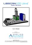
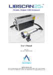
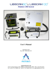
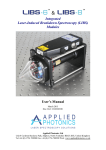
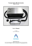
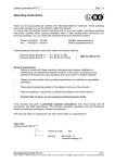
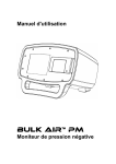
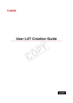
LIBS Workstation™
Model No. 0118
User’s Manual
February 2007
Doc. Ref.: UM/0118/00
Applied Photonics Ltd
Unit 8 Carleton Business Park, Skipton, North Yorkshire BD23 2DE, United Kingdom
Tel +44 (0) 1756 708900 Fax +44 (0) 1756 708909 Web: www.appliedphotonics.co.uk
Contents
1.
Introduction
Page
3
2.
Safety
2.1
Laser radiation
2.2
Note on testing of laser safety window
2.3
Electrical
4
4
5
5
3.
General description
3.1
Overview
3.2
The laser source
3.3
The articulated arm
3.4
The LIBS head
3.5
The geared column and rotary stage
3.6
The sample / experimental chamber
6
6
6
6
7
8
9
4.
Operating procedure
11
5.
Maintenance and inspection
13
Appendices
A1
Certificate of Conformity
© 2007 Applied Photonics Ltd
14
Page 2 of 14
1
Introduction
The concept behind the LIBS Workstation™ was born out of desire to add to our laboratory facilities a
highly adaptable LIBS instrument suitable for a wide range of research and development applications.
Our laboratory and R&D requirements are such that we needed a LIBS instrument with the following
capabilities and features:
•
•
•
•
•
•
•
•
•
•
A modular design concept (laser source, LIBS head, sample chamber, etc)
Co-axial laser transmission and plasma light collection optics
Broad-band spectral response (180 – 900 nm)
A compact and relatively light weight LIBS head (which essentially means that it does not contain the laser head)
The ability to direct the laser beam at any angle between vertical and horizontal
The ability to precisely adjust the focal plane of the laser beam
An integrated low-power visible alignment laser
The ability to select an appropriate laser and laser operating wavelength
The ability to operate the LIBS head in stand-off mode (range up to several metres)
A large and highly adaptable sample / experimental chamber offering full containment of the laser radiation (Class 1)
and with provision for air / fume extraction
From this “wish list”, the LIBS Workstation™ was born:
Laser head
support
assembly
Articulated arm
launch module with
integral 635 nm
alignment laser
Side entry port
for LIBS head
(fitted with
flexible gaiter)
Articulated
arm (five
degrees of
freedom)
Top entry
port for
LIBS head
Air extract
vent
LIBS head
Sample /
experimental
chamber
Laser head
Geared vertical
column with
rotary stage
Laser safety
window
Air inlet
filter port
Mobile
optical table
Laser power
supply unit
General view of the LIBS Workstation™
© 2007 Applied Photonics Ltd
Page 3 of 14
2
Safety
2.1
Laser radiation
The LIBS Workstation™ is designed to be a research and development tool for use by organisations
interested in conducting their own LIBS R&D program. It is imperative, therefore, that the LIBS
Workstation™ is operated only by suitably trained and experienced persons who are fully aware of the
hazards inherent to this type of high-power laser equipment. It is imperative also that, prior to using the
equipment, an appropriate risk assessment is conducted in such a way as to take account of the proposed
use of the equipment, the environment in which the equipment is to be operated, and how its use may
affect people who are not directly involved with the use of the equipment.
The LIBS Workstation may be configured in various ways by the user, including the use of an alternative
laser source and/or alternative laser wavelength, pulse energy, pulse repetition rate, etc. For the purposes
of this User’s Manual, it is assumed that the LIBS Workstation is fitted with a Q-switched Nd:YAG laser
(Quantel Brilliant B) operating at its fundamental wavelength of 1064 nm, with maximum pulse energy of
850 mJ, pulse duration of nominally 5 ns and maximum repetition rate of 10 Hz (ie. max average power
of 9 Watts). If any other laser and/or laser wavelength is to be used with the LIBS Workstation™, it is
imperative that advice is sought from Applied Photonics Ltd on the suitability of the alternative laser and
whether any modifications to the LIBS Workstation are necessary. Note that some of the images depicted
in this User’s Manual show a laser source incorporating a 2nd harmonic generator (implying a laser
wavelength 532 nm) – the 2nd harmonic generator was included in the images purely to replace another
component which was not available for the photo shoot.
The LIBS Workstation is designed to meet the laser safety requirements of the relevant European
standards (BS EN 60825) and USA standards (ANSI Z136.1 – 2000). Although the LIBS Workstation is
supplied with a sample chamber which provides adequate containment of the laser radiation, it is possible
for the user to operate the LIBS Workstation without the sample chamber (ie. operation in “open beam”
mode as may be required for certain types of experiment). Accordingly, it is necessary to consider the
LIBS Workstation as a Class 4 laser product and so, by definition, the equipment poses a risk of personal
injury (eye, skin injury) and poses a fire risk. As with all Class 4 laser products, appropriate safety
precautions must be taken as identified via a suitable risk assessment conducted by the user in
consultation with a suitably qualified and experienced Laser Safety Officer.
It is imperative that the LIBS Workstation is operated only by suitably qualified and experienced
personnel who are fully aware of the potential hazards associated with the use of this type of high-power
laser equipment. The most significant hazard relating to exposure of personnel to the laser radiation is
eye injury since direct or scattered laser radiation produced by the LIBS Workstation can cause serious
and permanent damage to the eyes including blindness - such damage may be instantaneous.
Precautions must be taken to avoid exposure of personnel to hazardous levels of laser radiation. Such
precautions may include the setting up of a temporary or permanent controlled area. Other measures may
also be necessary, as determined by appropriate and thorough assessment of the risks (ie. a risk
assessment) conducted by the personnel responsible for the safe use of the LIBS Workstation. Consult
the manual supplied with the laser for further guidance on the safe use of the laser.
The door of the sample chamber is equipped with an electrical interlock switch which is designed to
prevent activation of the laser unless the door is closed. The interlock switch connects to the laser power
supply using a length of BNC-to-BNC cable which is supplied with the LIBS Workstation. The cable
connects to the BNC port at the top rear of the sample / experimental chamber and to the interlock BNC
port on the front panel of the Quantel laser power supply.
© 2007 Applied Photonics Ltd
Page 4 of 14
IMPORTANT
2.2
•
NEVER allow unauthorised and/or untrained personnel operate the LIBS Workstation.
•
ALWAYS use appropriate laser safety protective eyewear when operating the LIBS Workstation
in “open-beam” configuration – you should seek advice from your Laser Safety Officer on this
matter.
•
ALWAYS switch the instrument off when not in use and remove the key from the keyswitch of
the laser power supply to prevent unauthorised activation.
•
NEVER operate the LIBS instrument in areas where explosive gas mixtures may be present.
•
NEVER place inside the sample chamber flammable liquids or any other material which may give
rise to flammable / explosive gas mixtures. Activation of the laser under these conditions could
result in an explosion leading to severe personal injury and/or fire hazard.
•
ALWAYS thoroughly inspect the LIBS Workstation for damage prior to use. Particular attention
should be given to the laser safety window and electrical safety interlocks fitted to the door of the
sample chamber.
•
NEVER point the LIBS head at a person (even with laser switched off), especially towards the
eyes, even if the person is wearing laser safety eyewear. The laser should be considered
“active” unless the laser power supply is deactivated and the safety shutter fitted to the laser
head is switched to the OFF position.
Note on testing of the laser safety window
The laser safety window material is rated at OD 6+ @ 1064 nm. It therefore provides adequate protection
against scattered laser light of wavelength 1064 nm. It provides no protection at other laser wavelengths
and so it is the responsibility of the user of the LIBS Workstation to ensure that it is appropriate for the
type of laser being used with the LIBS Workstation.
Applied Photonics Ltd have carried out tests on the performance of the laser safety window when
exposed to laser radiation from a Q-switched Nd:YAG laser (Quantel Brilliant B, 850 mJ, 5 ns pulse
length, 10 Hz pulse repetition frequency). The tests were conducted in accordance with European
standard BS EN 207:1999. The test essentially consists of exposing the window to a fluence of at least
0.5 J cm-2 for at least 100 laser pulses. The results of the tests concluded that the window material is able
to safely attenuate the laser radiation by at least a factor of 106.
2.3
Electrical
The laser head and laser power supply of the LIBS Workstation contain electrical circuits operating at
potentially lethal voltage and current levels. Before removing any access covers, isolate mains power
from the laser and depress the capacitor discharge switch located at the rear of the laser power supply.
Consult the manual supplied with the laser for further guidance on the safe use of the laser.
Two fluorescent lights (36 Watts total) are fitted to the inside of the sample chamber to provide
illumination. These lights are of the automotive type, ie. they require a 12 VDC electrical supply. The
LIBS Workstation is supplied with a mains adapter which provides 12 VDC (5 Amp max.) from either a
110 VAC or 230 VAC (50-60 Hz) source. The mains adapter is of the SELV type and so does not present
an electric shock hazard. The lead from the mains adapter connects to an electrical socket located at the
top rear of the sample chamber. The polarity of the socket is centre pin positive.
© 2007 Applied Photonics Ltd
Page 5 of 14
3
General description
3.1
Overview
A general view of the LIBS Workstation is given in figure 1 on page 3 of this User’s Manual. The LIBS
head contains the optics used to focus the laser beam onto a target sample and to collect plasma light from
the laser-induced plasma. The focal plane of the laser beam may be adjusted manually by the user. The
LIBS head is connected to the laser via an articulated arm of length approx. 1.5 metres and having 5
degrees of freedom. The articulated arm is used to transmit the laser beam to the LIBS head while
allowing a high degree of freedom of movement of the LIBS head. This allows the user to direct the laser
beam emitted from the LIBS head in any desired direction and at any position within the reach of the
articulated arm (approx. 1.5 metres). The geared column and rotary stage are used to adjust the height of
the LIBS head above the optical table and to allow rotation of the LIBS head so that the laser beam may
be directed at any angle between horizontal and vertical. Once the correct height and orientation of the
LIBS head has been achieved, the geared column and rotary stage may each be locked off so that the
position of the LIBS head is maintained. The LIBS Workstation may be used in “open beam” mode by
directing the laser beam emitted from the LIBS head to the sample material to be analysed. Alternatively,
the sample chamber may be used (as depicted in the following figure) in order to provide containment of
the laser radiation for increased safety of the user. The sample chamber is equipped with two side ports
and one top port, each designed to accommodate the LIBS head. A flexible gaiter may be used with the
side ports (as illustrated in the following figure) allowing the user to adjust the angle of the laser beam
incident on a sample located inside the chamber.
3.2
The laser source
The LIBS Workstation may be supplied with various laser sources or may be designed to accommodate
an existing laser at the user’s facility. If you require us to supply the LIBS Workstation with a preinstalled laser, we recommend the Quantel Brilliant B laser which offers high pulse energy (up to 850 mJ
@ 1064 nm) from a relatively compact device. This laser is also easily configured for alternative
(harmonic) wavelengths by simply adding the appropriate module(s) to the laser head.
3.3
The articulated arm
The articulated arm and associated launch module are shown in the following images. The arm consists
of an input and output flange, two tubes (50 mm OD, ~550 mm length) and five rotating “knuckle joints”
each of which contains a high-energy, dual-wavelength YAG mirror. Each mirror is mounted in a
precision-engineered aluminium alloy housing with three micro-positioner screws for angular adjustment
of the mirror. The two tubes are of length ~550 mm which gives the arm a reach of approaching ~1.1
metre.
Launch module
Flexible
gaiter port
Articulated arm
View of LIBS Workstation illustrating the articulated arm and launch module
© 2007 Applied Photonics Ltd
Page 6 of 14
The launch module contains the optics required to launch the Nd:YAG laser beam and the visible
alignment laser beam into the articulated arm. The optics in the launch module and the mirrors in the
articulated arm are precisely aligned during installation of the laser. It is strongly recommended that
the user does not make adjustments to any of these components as special tools and methods are
required for correct alignment of the laser beams.
3.4
The LIBS head
The LIBS head contains the optics required to focus the laser beam and to collect the plasma light for
transmission to an optical spectrograph. The articulated arm connects to the LIBS head via the arm
output flange. A removable beam tube is fitted to the output aperture of the LIBS head. An SMA
connector (located on the underside of the LIBS head) is used to provide fiber-optic connection to the
optical spectrograph (not shown).
View of one possible configuration of the LIBS Workstation without the use of the sample chamber
A two-lens (1” diameter) beam expander is used to adjust the focal plane of the laser beam. The
separation of the lens-pair may be adjusted by rotating the knob located on the left side of the LIBS head
(see image above). Clock-wise rotation of the focus knob increases the distance to the focal plane, and
vice-versa. With the lens-pair supplied with the LIBS Workstation, the focal plane may be adjusted
between approximately 300 mm and 2000 mm as measured from the side panel of the LIBS head (ie.
excluding the beam tube). The laser beam passes through a 2” diameter pierced mirror which is located
immediately down-stream of the beam expander and tilted at 45 degrees with respect to the axis of the
laser beam (see following image). A second lens-pair (2” diameter) is used to image the plasma light
onto the plane of the SMA connector. The position of the SMA connector may be adjusted in the X, Y
© 2007 Applied Photonics Ltd
Page 7 of 14
and Z directions. For a given experiment, the position of the SMA connector should be adjusted to
provide optimum transmission of plasma light to the spectrograph.
Inside view of LIBS head
3.5
The geared vertical column and rotary stage
The geared column allows the LIBS head to be raised and lowered in a vertical direction above the optical
table. The geared column is fitted with a rotary stage which allows the LIBS head to be rotated about the
axis of the stage, allowing the laser beam to be directed at any required angle.
Geared
vertical
column
Locking nut
for vertical
column
Handle for
vertical
column stage
Attachment
bracket for
LIBS head
Handle for
rotary stage
head
Vernier scale
displaying
angle
Front view of rotary stage
© 2007 Applied Photonics Ltd
Page 8 of 14
Locking nut
for vertical
column
Handle for
raising /
lowering vertical
column stage
Handle for
rotary stage
Locking
screw for
rotary stage
Rear view of geared column / rotary stage with LIBS head attached
3.6
The sample / experimental chamber
The main features of the sample / experimental chamber are illustrated in the following figures.
Electrical connections
for door interlock switch
and internal lighting
(sockets at rear)
Top entry port
for LIBS head
Air extract port
(integral HEPA filter)
Cable entry port
(not in view)
Upper side
entry port for
LIBS head
Laser safety window
(OD 6+ @ 1064 nm)
Lower side entry
port for LIBS head
(fitted with inlet air
filter cover plate)
View of sample chamber illustrating main components
© 2007 Applied Photonics Ltd
Page 9 of 14
Door
interlock
switch
Air extract
port fitted with
internal light
baffle plate
Beam tube
of LIBS
head (LIBS
head fitted
to top port)
Cable entry
port fitted with
internal light
baffle plate
Lower side
port fitted
with air
inlet filter
and light
baffle plate
Optical
breadboards
(M6 tapped
blind holes on
25 mm centres
Inside view of sample chamber with LIBS head fitted to top entry port
(beam tube can be seen entering the chamber from the top)
A flexible gaiter may be fitted to either of the side entry ports, the purpose of which is to allow the user to
direct the laser beam into the sample chamber at various angles between horizontal and approximately 45
degrees from the vertical whilst maintaining containment of the laser radiation. This feature allows LIBS
experiments to be conducted with the laser beam impinging the sample at various angles. This is
particularly useful when conducting LIBS analysis of liquids.
Flexible gaiter for attachment
to side entry port.
The beam tube of the LIBS
head is designed to slide into
the flexible gaiter.
Beam tube of
LIBS head
View of sample chamber fitted with flexible gaiter port
© 2007 Applied Photonics Ltd
Page 10 of 14
View of sample chamber with laser beam impinging sample at an angle of ~45 degrees
4
Operating procedure
The operating procedure is governed primarily by the operation of the laser and the spectrograph,
instructions for which are provided by the manufacturer of each device. The electrical connection
between the sample chamber door interlock switch and the laser power supply must be made before
activating the laser. The LIBS Workstation is supplied with a BNC-to-BNC cable of approximately 2
metres length for this purpose. Connection to the laser power supply should be as instructed by the laser
manufacturer (see documentation supplied with laser). Correct operation of the door interlock should be
checked out before using the LIBS Workstation.
The LIBS head may be used in various ways, as illustrated in the following images. The method of
attachment is illustrated in the images and is largely self-explanatory. Care should be exercised in the
manual handling of the LIBS head and articulated arm as each contains sensitive optical components.
Excessive shock / vibration may result in misalignment of the optical components. If this is suspected,
the LIBS Workstation should be immediately taken out of service and advice sought from the
manufacturer as to what remedial action may be required.
Views of LIBS Workstation illustrating various possible configurations of LIBS head with the sample chamber
© 2007 Applied Photonics Ltd
Page 11 of 14
Views of LIBS Workstation illustrating various possible configurations of LIBS head without the sample chamber
Correct focus of the laser beam is achieved by adjusting the focus control knob on the LIBS head. It will
be necessary to adjust the fibre-optic SMA connector in the X, Y and Z directions in order to achieve
optimum transmission of plasma light to the spectrograph. This is best achieved by conducting a
“dummy run” LIBS experiment using a piece of steel as a sample target and operating the spectrograph in
“free run” mode. The X, Y and Z position of the fibre-optic SMA connector port should then be adjusted
to maximise the recorded spectral intensity.
Warning – depending upon the nature of the experimental conditions, there is a risk of emission of
dangerous levels of laser radiation from the SMA connector port. It is recommended, therefore,
that the user of the LIBS Workstation wears appropriate eye protection whenever making
adjustments to the SMA connector port or when operating the LIBS Workstation without the fibreoptic cable connected to both the SMA connector port and the spectrograph.
Image of SMA positioner
© 2007 Applied Photonics Ltd
Image of SMA positioner fitted to port of LIBS head
Page 12 of 14
Blanking covers are provided with the LIBS Workstation for fitting to unused side entry ports or the top
entry port. It is important that these blanking ports are used to ensure the sample chamber provides
adequate containment of the laser radiation. One of the side entry port blanking covers is fitted with a
filtered air inlet port to allow air to enter the sample chamber when air extraction is utilized. The LIBS
Workstation is equipped with a cable entry port on the right hand side panel of the sample chamber (as
illustrated in the following figure). The cable entry port is designed to allow cables to be fed into the
sample chamber without compromising the containment of the laser radiation. To install a cable, it is
necessary to first remove the outer cover plate and the internal light baffle plate. Cables are fed into the
cable entry port from below, pass through the rubber barrier and then back down the inside of the port
behind the internal light baffle plate – examination of the cable entry port with the outer cover removed
should make this procedure self-explanatory.
Cable entry
port
Cables are fed up into the
port via the opening in the
lower face of the cover plate
View of right hand side of sample chamber showing cable entry port
5
Maintenance and inspection
The LIBS Workstation should be periodically inspected for signs of damage or wear and tear. Of
particular importance are the safety features including the laser safety window and the door interlock
switch mechanism. If any damage to the laser window material is observed or suspected, the LIBS
Workstation should be temporarily removed from service until a replacement window is fitted. The inlet
air filter and the outlet air HEPA filter should be inspected at least yearly and replaced if necessary.
Replacement parts are available from the manufacturer.
© 2007 Applied Photonics Ltd
Page 13 of 14
Appendix A1
Certificate of Conformity
Applied Photonics Limited
Unit 8 Carleton Business Park
Skipton North Yorkshire
BD23 2DE United Kingdom
EC
Declaration of Conformity
Applied Photonics Ltd declares that the product listed below has been designed and manufactured in
compliance with the relevant standards as follows:
Product name:
LIBS Workstation™
Model Number:
0118
Laser product safety
This device conforms with the principal objectives of safety of laser products by application of the
following standards: BS EN 60825-14:2004 and BS EN 207:1999
Electrical Safety
This device conforms with the principal safety objectives of the European Directive 73/23/EEC, as
implemented by the Electrical Equipment (Safety) Regulations 1994, by application of the following
standard: BS EN 61010-1:2001.
Electro-Magnetic Compatibility
This device conforms with the principal objectives of the European Directive (89/336/EEC) as amended
by 91/31/EEC and 93/68/EEC, as implemented by The EMC Regulations (SI 1992 No. 2372 and
amendment SI 1994 No. 3080), by application of the following standard: BS EN 61326-1:1997
Year of affixation of the CE Marking:
2007
Signed:
Name:
Andrew I. Whitehouse
Title:
Managing Director
Place:
Applied Photonics Ltd, Unit 8 Carleton Business Park, Skipton, North Yorkshire BD23
2DE, United Kingdom
Date:
15 February 2007
© 2007 Applied Photonics Ltd
Page 14 of 14