1
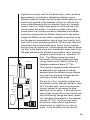
same type and sub-type as the component (See Components/ Associate Model) and a copy of the model is added to the component. If a component has a parameter which may be edited by the user, the simulator displays a dialog showing the component value (in the units of measure stored with the parameter). The user may change the value and the program stores the changed value with the components data. In order to display the editable parameters in appropriate units, the Units Library is scanned until the units type (e.g. Pressure, Temperature etc.) and units of measure (e.g. Torr, atmospheres, mbar etc.) are matched. The Units Library contains conversion factors to change from one unit of measure to another. The parameter for the component is stored in an agreed internal format (system units), and presented to the user in converted format. Linking Components Together When you link the ports of two components you add to each connection port a pointer to the other port. Each port can have an arbitrary number of such links. The connecting lines which appear on the schematic diagram are derived from the linkage information but are not part of the primary data structure used to store the components. Saving a Schematic Drawing to a File Each component, in turn is saved to an output stream associated with the file selected as the output (See File/Save). The current parameter values (in system units) and their current units of measure are also saved so that if you subsequently retrieve the component, it will present the parameter in the same units of measure as you last used. The list of pointers on each connection port is saved (see Linking Components Together), but the data structure for the link lines is not. The copy of the mathematical model referenced by the compo75