1
DAC Configuration and Control
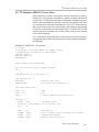
7.3 DAC Configuration and Control
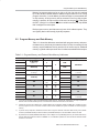
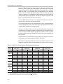
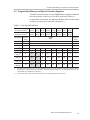
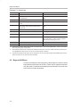
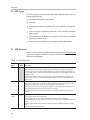
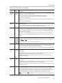
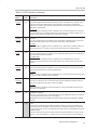
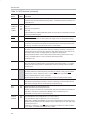
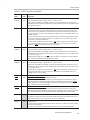
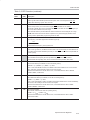
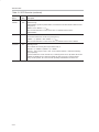
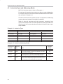
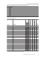
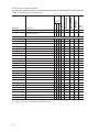
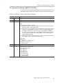
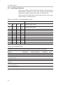
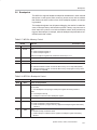
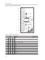
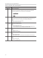
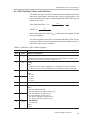
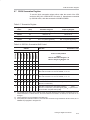
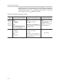
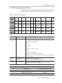
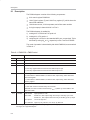
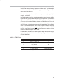
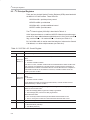
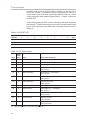
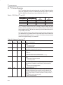
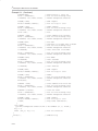
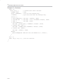
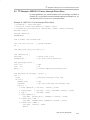
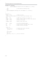
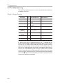
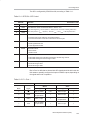
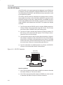
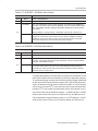
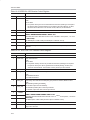
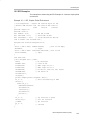
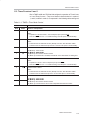
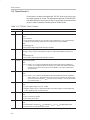
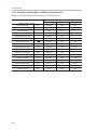
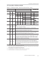
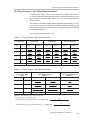
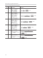
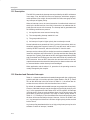
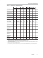
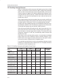
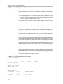
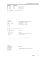
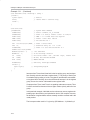
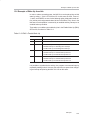
Each DAC has a corresponding control register DACxCON (x = 0 to 3), which
is used to configure its mode of operation, as summarized in Table 7−4.
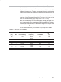
Table 7−4. DAC Control Registers
DACSEL
SFR x
DAC
7
6
5
4
3
2
1
0
Reset
Value
0
COR0
EOD0
IDAC0DIS
0
0
SELREF0
DOM0_1
DOM0_0
63h
1
COR1
EOD1
IDAC1DIS
0
0
SELREF1
DOM1_1
DOM1_0
63h
2
0
0
0
0
0
SELREF2
DOM2_1
DOM2_0
03h
3
0
0
0
0
0
SELREF3
DOM3_1
DOM3_0
03h
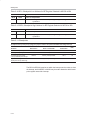
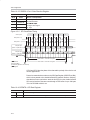
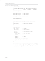
sel = 04h
SFR B5h
sel = 04h
SFR B6h
sel = 05h
SFR B5h
sel = 05h
SFR B6h
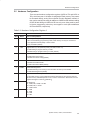
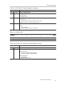
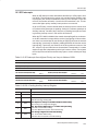
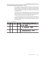
where
Bit
Name
Meaning(s)
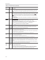
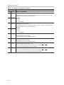
COR0
Current Over Range
Write:
COR1
0: Release from high-impedance state back to normal mode unless
an over-range (still) exists.
Write:
1: NOP
Read:
0: IDACx is not over-current
Read:
1: IDACx is over 125mA.
If EODx = 0, the indication is immediate.
If EODx = 1, the over-current condition must occur for three consecutive ticks of MSEC.
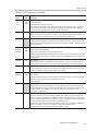
EOD0
EOD1
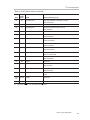
SELREFx
Enable Over-Current
Detection
0: Disable over-current detection.
1: Enable over-current detection (default).
Select Reference
0: DACx reference is AVDD (default).
1: DACx reference is REFOUT/REF IN+ pin (see SFR DCh).
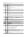
and
DOMx[1:0]
Voltage VDACx, x = 0,1,2,3
Current IDACx, x = 0,1
00
Normal output
IDAC controlled by IDACxDIS
01
Output off 1k to AGND
IDAC off
10
Output off 100k to AGND
IDAC off.
11
Output off high impedance (default)
IDAC off (default)
Digital-To-Analog Converters
7-5