1
DAC Technology and Limitations
7.4 DAC Technology and Limitations
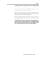
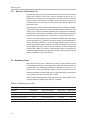
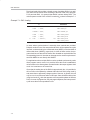
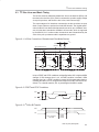
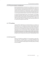
The DACs in the MSC1211 are based upon the 16-bit DAC type DAC8531,
also manufactured by Texas Instruments. Consequently, all DACs use a string
of tapped resistors to establish a scale of voltages that are ensured to be
monotonic, which is essential for many closed-loop control systems. This is
effectively 65,536 resistors that can be tapped for voltages from AGND to the
DAC reference voltage.
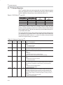
The output amplifiers for the DACs cannot reach 0V and must have at least
1.5V of operating headroom; that is to say, AVDD should be 1.5V above the
maximum voltage output by a DAC. Due to the former constraint, DAC codes
below about 0x0200 are not recommended and are precluded from linearity
calculations used in the preparation of electrical characteristics, as found in
product datasheets. Increased nonlinearity may also be seen for near fullscale codes when the headroom constraint is not satisfied. For example, when
a DAC uses the on-chip 2.5V reference and AVDD is less than 4.0V.
The linearity of the DAC can be improved with the techniques discussed in Application Note SBAA112, MSC1211/12 DAC INL Improvement, available for
download at www.ti.com.
For DACs operating in voltage mode, the reference voltage may extend to
AVDD but the output voltage should remain 1.5V lower.
The nominal reference current is 25µA per DAC. Therefore, when the internal
voltage reference is disabled and VREF is derived from an external source connected to the REFOUT/REF IN+ pin, the origin and impedance of the source
voltage should be considered.
Digital-To-Analog Converters
7-7