1
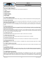
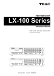
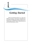
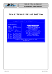
PIP11 User Manual High-Tech • Made in Switzerland PACKED INDUSTRIAL PC WITH PENTIUM-M PROCESSOR The PIP11 is a low power, highly integrated rugged industrial PC with a specially designed aluminum housing. This allows the PIP11 to operate in a standard or also in a harsh environment without fan or ventilation holes. The design integrates standard connectors for easy connection. It can be used for any PC application where a complete solution is needed. The PIP11 is 100% PC/AT compatible, and can easily be mounted on a 35 mm DIN rail. The PIP11 housing offers space for a 2.5 inch hard disk and a CD-ROM drive. With the integrated PC/104 (-PLUS) interface flexible expansion possibilities are available. Fully bootable FLASH disks are supported for projects where hard disks cannot be used. Particular precautions have been taken that the EMC for the entire system is within the CE and FCC limits. All these features make the PIP11 the ideal solution for the industry wherever a flexible, rugged and durable complete Industrial PC is needed. Features: ● Pentium-M 745 with 1.8 GHz and 2 MByte Level2 ● ● ● ● ● ● ● ● ● ● ● ● Standard PC interfaces (PS/2, parallel port) ● 2 serial ports with RS232 interface ● 2 serial ports with RS232 or RS485 interface Cache Intel Mobile Technology components Up to 1.5 GB DDR333 memory with ECC Up to 512 MB soldered down memory with ECC Suspend to Disk (S4) support 3D graphics with up to 64 MByte shared memory 1 Ethernet port (10M/100M/1G Bit/s) 3 FireWire 1394b ports (800 MBit/s) 2 USB 2.0 ports (480 MBit/s) 2 SATA-I ports (150 MByte/s) 2 Ultra DMA-100 IDE ports 1 MByte Firmware Hub 2007 by MPL AG (optional) ● Four full featured PC/104(-PLUS) slots without ISA Master, ISA DMA and ISA End Transfer capability ● Two-Stage watchdog timer with hardware reset ● ● ● ● ● 1 capability UPS (optional) Galvanically isolated power input (optional) AC’97 codec (optional) CAN interface (optional) RoHS compliant MEH-10106-021 Rev. B PIP11 User Manual High-Tech • Made in Switzerland TABLE OF CONTENTS 1 INTRODUCTION.................................................................................................... 6 1.1 ABOUT THIS MANUAL.................................................................................................. 1.2 SAFETY PRECAUTIONS AND HANDLING.................................................................. 1.3 ELECTROSTATIC DISCHARGE (ESD) PROTECTION................................................ 1.4 EQUIPMENT SAFETY.................................................................................................... 1.5 MANUAL REVISIONS.................................................................................................... 1.5.1 Related Products....................................................................................................... 1.5.2 Revision History......................................................................................................... 1.6 RELATED DOCUMENTATION...................................................................................... 1.7 ORDERING INFORMATION.......................................................................................... 6 6 6 6 7 7 7 8 8 2 GENERAL INFORMATION.................................................................................... 9 2.1 ELECTRICAL................................................................................................................. 9 2.1.1 Processor.................................................................................................................. 9 2.1.2 Chipset...................................................................................................................... 9 2.1.3 BIOS ROM................................................................................................................ 9 2.1.4 Memory..................................................................................................................... 9 2.1.5 RTC........................................................................................................................... 9 2.1.6 PC/104-PLUS Interface............................................................................................. 9 2.1.7 Graphics.................................................................................................................... 9 2.1.8 USB........................................................................................................................... 9 2.1.9 Serial RS232 Ports.................................................................................................... 9 2.1.10 RS485/RS422 Interface Modules (Optional).......................................................... 10 2.1.11 Parallel Port........................................................................................................... 10 2.1.12 IDE (PATA) Ports.................................................................................................. 10 2.1.13 SATA-I Ports.......................................................................................................... 10 2.1.14 Floppy Disk............................................................................................................ 10 2.1.15 FireWire 1394b...................................................................................................... 10 2.1.16 Ethernet................................................................................................................. 10 2.1.17 Keyboard / Mouse................................................................................................. 10 2.1.18 AC’97 Audio Controller.......................................................................................... 10 2.1.19 Speaker................................................................................................................. 10 2.1.20 Indicators............................................................................................................... 11 2.1.21 Reset Button, Power Button.................................................................................. 11 2.1.22 Hardware Watchdog Timer.................................................................................... 11 2.1.23 Temperature Sensors............................................................................................ 11 2.1.24 Specialties............................................................................................................. 11 2.2 PHYSICAL.................................................................................................................... 12 2.2.1 Housing................................................................................................................... 12 2.2.2 Form factor.............................................................................................................. 12 2.2.3 Weight..................................................................................................................... 12 2.3 POWER........................................................................................................................ 12 2.3.1 Power supply........................................................................................................... 12 2.3.2 Fuse........................................................................................................................ 12 2.3.3 RTC Battery............................................................................................................. 12 2.3.4 Input Power............................................................................................................. 12 2.4 ENVIRONMENT........................................................................................................... 12 2.4.1 Temperature Range................................................................................................ 12 2.4.2 RELATIVE HUMIDITY............................................................................................. 12 2007 by MPL AG 2 MEH-10106-021 Rev. B PIP11 User Manual High-Tech • Made in Switzerland 3 DIMENSIONS....................................................................................................... 13 3.1 TOP VIEW.................................................................................................................... 3.2 BOTTOM VIEW............................................................................................................ 3.3 SIDE VIEW 1................................................................................................................ 3.4 SIDE VIEW 2................................................................................................................ 3.5 SIDE VIEW 3................................................................................................................ 3.6 SIDE VIEW 4................................................................................................................ 13 14 15 16 17 17 4 CONNECTORS.................................................................................................... 18 4.1 PARALLEL PORT (J2) CONNECTOR......................................................................... 18 4.2 SERIAL-1 (J46) AND SERIAL-3 (J35) CONNECTOR................................................. 19 4.3 SERIAL-2 (J21) AND SERIAL-4 (J10) CONNECTOR................................................. 19 4.4 EXTERNAL POWER (J1) CONNECTOR..................................................................... 20 4.4.1 External Power Connector Pin Out.......................................................................... 20 4.4.2 Mounting An External Reset And Power Button...................................................... 20 4.4.3 Power Up Behaviour................................................................................................ 20 4.5 PS/2 KEYBOARD (J8) AND MOUSE (J9) CONNECTORS......................................... 21 4.6 FIREWIRE 1394b (J26, J20, J15) CONNECTORS...................................................... 21 4.7 DUAL USB (J43) CONNECTOR.................................................................................. 21 4.8 DVI-I (J30) CONNECTOR............................................................................................ 22 4.9 10M/100M/1G ETHERNET (J49) CONNECTOR.......................................................... 22 5 OPERATION........................................................................................................ 23 5.1 BLOCK DIAGRAMS..................................................................................................... 5.2 PC/AT FUNCTIONALITY............................................................................................. 5.3 STATUS INDICATORS................................................................................................ 5.3.1 Power Indicator LED................................................................................................ 5.3.2 Reset Indicator LED................................................................................................ 5.3.3 HDD Indicator LED.................................................................................................. 5.3.4 IEEE1394b Indicator LED........................................................................................ 5.3.5 LAN ACT Indicator LED........................................................................................... 5.3.6 LAN Spd Indicator LED........................................................................................... 5.3.7 USER1, USER2 Indicator LEDs.............................................................................. 5.4 BATTERY CIRCUIT...................................................................................................... 5.5 HARDWARE WATCHDOG.......................................................................................... 5.6 RS485 / RS422 INTERFACES..................................................................................... 23 24 24 24 24 24 24 24 24 24 24 24 25 6 SOFTWARE......................................................................................................... 26 6.1 BIOS............................................................................................................................. 26 6.2 DEVICE DRIVERS........................................................................................................ 26 7 COPYRIGHT........................................................................................................ 29 8 DISCLAIMER....................................................................................................... 29 9 TRADEMARKS.................................................................................................... 29 10 SUPPORT.......................................................................................................... 29 10.1 FAQ............................................................................................................................ 29 10.2 SERIAL NUMBER AND REVISION........................................................................... 29 10.3 CONTACT MPL AG.................................................................................................... 29 2007 by MPL AG 3 MEH-10106-021 Rev. B PIP11 User Manual High-Tech • Made in Switzerland TABLE OF FIGURES Figure 1: PIP Housing Top View............................................................................................ 12 Figure 2: PIP Housing Bottom View...................................................................................... 13 Figure 3: PIP Housing Side View 1........................................................................................ 14 Figure 4: PIP Housing Side View 2........................................................................................ 15 Figure 5: PIP Housing Side View 3........................................................................................ 16 Figure 6: PIP Housing Side View 4........................................................................................ 16 Figure 7: Parallel Port Connector (DSUB 25 female) (Connector: Compona, 329 156-6)..... 17 Figure 8: Serial Port Connector (DSUB 9 male) (Connector: Compona, 329 151-6)............. 18 Figure 9: Serial Port Connector (DSUB 9 male) (Connector: Compona, 329 151-6)............. 18 Figure 10: Power Connector (Connector: Phoenix Contact AG, MC1,5/4GF-3,81)............... 19 Figure 11: External Reset and Power Button Switch............................................................. 19 Figure 12: PS/2 Keyboard & Mouse Connector (Connector: Compona, 129108-7).............. 20 Figure 13: FireWire 1394b bilingual Connector (Connector: Molex, 45241-0001)................. 20 Figure 14: Dual USB (Type A) Connector (Connector: FCI, 72309-0010B).......................... 20 Figure 15: DVI-I Connector (Connector: Samtec, DVI-29-AW-FT)........................................ 21 Figure 16: RJ45 Connector (Connector: Bel Fuse 0826-1K1T-23)........................................ 21 Figure 17: PIP11-1 Block Diagram........................................................................................ 22 Figure 18: PIP11 Label.......................................................................................................... 28 2007 by MPL AG 4 MEH-10106-021 Rev. B PIP11 User Manual High-Tech • Made in Switzerland 1 INTRODUCTION 1.1 ABOUT THIS MANUAL This manual, the PIP Technical Reference Manual and the PIP11 BIOS User Manual provides all the information necessary to handle and configure the PIP11. This manual is written for technical personnel responsible for integrating the PIP11 into their systems. It is strongly recommended to read this manual before the PIP11 is switched on. 1.2 SAFETY PRECAUTIONS AND HANDLING For personal safety and safe operation of the PIP11, follow all safety procedures described here and in other sections of the miscellaneous manuals. ● Remove power from the system before installing (or removing) the PIP11, to prevent the possibility of personal injury (electrical shock) and / or damage to the product. ● Handle the product carefully; i.e. dropping or mishandling the PIP11 can cause damage to assemblies and components. ● Do not expose the equipment to moisture. WARNING There are no user-serviceable components on the PIP11. 1.3 ELECTROSTATIC DISCHARGE (ESD) PROTECTION Various electrical components within the product are sensitive to static and electrostatic discharge (ESD). Even a small static discharge can be sufficient to destroy or degrade a component's operation! With an open housing, do not touch any electronic components. Handle or touch only the unit chassis. 1.4 EQUIPMENT SAFETY Great care is taken by MPL AG that all its products are thoroughly and rigorously tested before leaving the factory to ensure that they are fully operational and conform to specification. However, no matter how reliable a product, there is always the remote possibility that a defect may occur. The occurrence of a defect on this device may, under certain conditions, cause a defect to occur in adjoining and/or connected equipment. It is your responsibility to protect such equipment when installing this device. MPL accepts no responsibility whatsoever for such defects, however caused. 2007 by MPL AG 5 MEH-10106-021 Rev. B PIP11 User Manual High-Tech • Made in Switzerland 1.5 MANUAL REVISIONS 1.5.1 Related Products Revision A Related To • PIP11-1 Rev. A, B 1.5.2 Revision History Revision A B 2007 by MPL AG Date 2006-09-20 2007-04-02 Description Initial release of this document. - 2.4.1: Additional information on temperature ranges inserted 6 MEH-10106-021 Rev. B PIP11 User Manual High-Tech • Made in Switzerland 1.6 RELATED DOCUMENTATION The following documents are related to this manual. For detailed Information about a specific PIP11 setting or feature please refer to this additional manuals. Reference [1] [2] Description PIP11 BIOS User Manual PIP Technical Reference Manual MPL AG: MPL AG: Available from www.mpl.ch/t2400.html www.mpl.ch/t2400.ht ml 1.7 ORDERING INFORMATION The table below gives you an overview of the different PIP11 variants and its features. Product Name PIP11-1 PIP11-xCx 2007 by MPL AG Product Features • 1.8 GHz Pentium-M Dothan 745 with 2 MByte Level2 Cache • 512 Myte soldered down On Board DDR333 Memory with ECC • 200 pin DDR333 SO-DIMM socket with ECC (up to 1 GB memory) • 82541PI GBit Ethernet controller • 3 1394b bilingual ports • PC/104 & PC/104-PLUS Interface • 2 RS232 ports, optionally additional 2 RS232 or RS485 ports possible • RoHS compliant • Custom Assembly for series with 100 pieces and more • Please contact MPL AG for further information There are also many more options available for: • Housing size, displays, touch, IP65 • PC/104-PLUS card -, PCI card -, PC-Card - and CF card extensions • CDROM • UPS, extended Input Power Module • Extended temperature • etc. Please have a look at our homepage for this on www.mpl.ch/t2441.html or contact MPL AG for further information. 7 MEH-10106-021 Rev. B PIP11 User Manual High-Tech • Made in Switzerland 2 GENERAL INFORMATION This chapter provides an overview of the PIP11 and its features. It outlines the electrical and physical specifications of the product and its power requirements. 2.1 ELECTRICAL 2.1.1 Processor • Pentium-M Dothan 745 1.8 GHz with 2 MByte Level2 Cache in 90 nm technology • Enhanced Intel SpeedStep technology • Supports catastrophic thermal protection 2.1.2 Chipset • Intel 855GME & 6300ESB • 400-MHz source-synchronous Frontside Bus • Supports ACPI-defined power states S1 (Stop Grant), S3 (Suspend to RAM), S4 (Suspend to Disk), S5 (Soft Off) 2.1.3 BIOS ROM • 1 MByte Firmware Hub • Easy BIOS update • BIOS source owned by MPL AG 2.1.4 Memory • DDR333 (PC2700) memory • Up to 512MByte on board with ECC • 200 pin SO-DIMM slot supports up to 1 GByte memory with ECC 2.1.5 RTC • Backed with field changeable on board battery 2.1.6 PC/104-PLUS Interface • • • • 8/16 bit memory and I/O PC/104 interface PC/104 DMA, Master and End Transfer not supported 32 bit PC/104-PLUS interface Up to 4 PC/104-PLUS bus master (PC/104-PLUS Spec. Rev. 2.0) 2.1.7 Graphics Intel IGD (Integrated Graphics Device) 250 MHz graphics core with 2D and 3D engine Dual Pipe independent display functionality 350-MHz, 24-bit RAMDAC LVDS port on 1.27mm header supports up to 1600 x 1200 (UXGA) and 1920 x 1080 (tested: 1280 x 1024, 1920 x 1080) • Digital Video Interface on DVI-I connector supports up to 1600 x 1200 (UXGA) (tested: 1600 x 1200) • Analog Video Interface on DVI-I connector supports up to 2048 x 1536 (QXGA) @ 75 Hz (tested: 1600 x 1200) • DVI-I connector is ESD protected • • • • • 2.1.8 USB • 3 Ports with 1.5 / 12 / 480 MBit/s (2 external, 1 internal) • Supports USB keyboards and mice as legacy devices • ESD protected 2.1.9 Serial RS232 Ports • 2 full modem serial RS232 ports, 16C550 compatible 2007 by MPL AG 8 MEH-10106-021 Rev. B PIP11 User Manual High-Tech • Made in Switzerland • • • • • • 2 ports can be equipped either with RS232 or with RS485/RS422 interface modules (both optional) COM1, COM3 with 16 byte FIFO COM2, COM4 with 128 byte FIFO Selectable transfer rates up to 230.4 kbaud Available on standard DB9 connectors ESD protected 2.1.10 RS485/RS422 Interface Modules (Optional) • • • • • 2 galvanically isolated half- or full-duplex ports Automatic RS485 half-duplex direction control Selectable transfer rates up to 230.4 kbaud Available on standard DB9 connectors ESD protected 2.1.11 Parallel Port • • • • • IEEE1284 compliant, SPP, EPP1.7, EPP1.9, ECP mode support Configurable as LPT1, LPT2, LPT3 Floppy disk on parallel port mode, with floppy power available Available on DB25 connector ESD protected 2.1.12 IDE (PATA) Ports • 2 Ports on 44 pin connectors with Master / Slave capability • Support of Ultra DMA-100 Mode 2.1.13 SATA-I Ports • 2 Ports on standard SATA connectors • Data transfer rates up to 150 MByte/s • Support of Soft RAID 2.1.14 Floppy Disk • Up to 2.88 MByte FDD supported • Signals can be routed to the parallel port connector (for an external floppy) 2.1.15 FireWire 1394b • • • • TI TSB82AA2 Controller 3 Ports on 1394b bilingual connectors support up to 800 MBit/s Provides VINCON power over Polyfuse to the FireWire connectors ESD protected 2.1.16 Ethernet • Intel 82541PI 10M/100M/1G Bit/s Ethernet controller • Connected over 66 MHz / 32 Bit PCI bus • ESD protected 2.1.17 Keyboard / Mouse • Available on 6 pin mini DIN connectors (PS/2) • ESD protected 2.1.18 AC’97 Audio Controller • AC’97 2.2 compliant • AC’97 function available over optional extension PCB called SoundPAN-1. With internal Speaker and external, on the user slot available, Line IN, Line OUT, Headphone and MIC interfaces. 2.1.19 Speaker • Available on an internal 10 pin header 2007 by MPL AG 9 MEH-10106-021 Rev. B PIP11 User Manual High-Tech • Made in Switzerland 2.1.20 Indicators • Power (green), CPU OverTemp (yellow blinking) and CPU CatastrophicTemp (green blinking after restart) LED • Reset (red) and power fail (red blinking) LED • HDD (IDE and SATA) activity (green) LED • IEEE1394 activity (yellow) LED • LAN link (green) and activity (green blinking) LED • LAN Spd LED (100MBit/s green, 1GBit/s yellow) • 2 user-programmable LED’s (yellow) 2.1.21 Reset Button, Power Button • Connection for an external remote reset and remote power button • ESD protected 2.1.22 Hardware Watchdog Timer • Two-Stage Watchdog with independent count values for each stage • Configurable granularity from 1µs to 10 min 2.1.23 Temperature Sensors • Monitors the CPU, the on board memory, the switching power supply and the PCB board temperature 2.1.24 Specialties • • • • UPS function (optional) Input voltage up to 48V (optional) Galvanic isolated Power Supply input (optional) CAN Extension (optional) 2007 by MPL AG 10 MEH-10106-021 Rev. B PIP11 User Manual High-Tech • Made in Switzerland 2.2 PHYSICAL 2.2.1 Housing • Aluminum • No ventilation holes • Easily mountable on 35 mm DIN rail 2.2.2 Form factor • Length: • Width: • Height: 270 mm (10.63 inch) standard version 440 mm (17.32 inch) Wintergarden version with PCI slot extension 162 mm (6.38 inch) 62.0 mm (2.44 inch) standard version 82.5 mm (3.25 inch) 120 mm (4.72 inch) 2.2.3 Weight • Typically 2.2 kg (4.85 lb.) (Standard housing, equipped with internal 2.5 inch HDD and CDROM) 2.3 POWER 2.3.1 Power supply • High-efficiency 6 channel switching regulator module • ATX behavior (Soft off) • Power input is ESD protected 2.3.2 Fuse • 5 x 20 mm, 3.15 AT 2.3.3 RTC Battery • Lithium coin cell CR2032 (20.0 x 3.2 mm) • 3 V / 230 mAh • Field changeable 2.3.4 Input Power • 8 VDC .. 28 VDC • Optional 20 VDC .. 48 VDC • The power usage can change in a wide range according to the needed CPU, memory, graphics and interfaces usage, as examples: • 12 W (512 Mbyte DDR333 SDRAM, HD, Windows XP Desktop Screen, GBit ETH Link, VIN = 12 V) • 26 W (512 Mbyte DDR333 SDRAM, HD, Windows XP with SiSoft Sandra Burn In Tool, GBit ETH Link, VIN = 12 V) 2.4 ENVIRONMENT 2.4.1 Temperature Range • Storage temperature range -45°C to 85°C • Operating temperature range -20°C to +60°C (+32°F to +140°F) (with full CPU, 3D video and memory usage, mounted on a DIN rail with freely natural convection) • Extended operating temperature range available (screening) 2.4.2 RELATIVE HUMIDITY • 5% to 95% non-condensing 2007 by MPL AG 11 MEH-10106-021 Rev. B 32.5 40.1 47.7 55.4 63.0 70.6 78.2 85.8 KEYB High-Tech Made in Switzerland P R - + SIDE VIEW 4 et Po w er Re s 12 PARALLEL D D 2 SERIAL 4 § SIDE VIEW 1 SERIAL 2 1394b SIDE VIEW 2 SERIAL 3 DVI-I USB 2.0 SERIAL 1 LAN High-Tech • Made in Switzerland H MOUSE 13 94 b L A N A CT LA N Sp d Us er 1 2007 by MPL AG Us er 270.0 106.2 PIP11 User Manual 3 DIMENSIONS 3.1 TOP VIEW SIDE VIEW 3 48.3 162.1 Figure 1: PIP Housing Top View MEH-10106-021 Rev. B Re s et PIP11 User Manual High-Tech • Made in Switzerland 3.2 BOTTOM VIEW 105.0 85.0 165.0 185.0 270.0 SIDE VIEW 2 SIDE VIEW 1 SIDE VIEW 4 SIDE VIEW 3 59.5 81.1 109.5 162.1 Figure 2: PIP Housing Bottom View 2007 by MPL AG 13 MEH-10106-021 Rev. B PIP11 User Manual High-Tech • Made in Switzerland 3.3 SIDE VIEW 1 (72.2), [109.7] 82,3 x 18,5 (82.5), [120.0] 229.6 254.6 270.0 17.7 21.2 64.7 81.8 85.0 106.8 122.5 147.5 176.4 185.0 201.4 251.1 221.0 168.9 165.4 106.9 103.4 73.3 DSUB-25 DSUB-9 DSUB-9 BOTTOM VIEW User Slot 2 82,3 x 18,5 TOP VIEW 8.5 User Slot 1 DSUB-9 SIDE VIEW 3 51.7 40.9 33.7 29.9 SIDE VIEW 4 24.3 62.0 Figure 3: PIP Housing Side View 1 Note: Use the numbers in parentheses for the higher versions (82.5 mm) [120 mm]. 2007 by MPL AG 14 MEH-10106-021 Rev. B PIP11 User Manual High-Tech • Made in Switzerland 3.4 SIDE VIEW 2 SIDE VIEW 4 21.6 24.5 TOP VIEW BOTTOM VIEW 8.5 22.6 23.0 30.6 252.3 232.0 208.2 190.6 185.0 163.9 144.1 124.3 108.0 91.7 85.0 52.1 25.0 75.5 23.2 270.0 22.1 SIDE VIEW 3 (82.5), [120.0] 62.0 Figure 4: PIP Housing Side View 2 Note: Use the numbers in parentheses for the higher versions (82.5 mm) [120 mm]. 2007 by MPL AG 15 MEH-10106-021 Rev. B PIP11 User Manual High-Tech • Made in Switzerland 3.5 SIDE VIEW 3 (82.5), [120.0] (77.9), [115.4] 144,9 67,7 TOP VIEW SIDE VIEW 2 59.5 94,4 109.5 162,1 8,5 4,6 62,0 57,4 SIDE VIEW 1 17,2 BOTTOM VIEW Figure 5: PIP Housing Side View 3 Note: Use the numbers in parentheses for the higher versions (82.5 mm) [120 mm]. (82.5), [120.0] (77.9), [115.4] 3.6 SIDE VIEW 4 144,9 94,4 TOP VIEW 52.5 67,7 102.5 107,5 162,1 8,5 62,0 57,4 35,4 4,6 SIDE SIDE VIEW 1 VIEW 2 17,2 BOTTOM VIEW Figure 6: PIP Housing Side View 4 Note: Use the numbers in parentheses for the higher versions (82.5 mm) [120 mm]. 2007 by MPL AG 16 MEH-10106-021 Rev. B PIP11 User Manual High-Tech • Made in Switzerland 4 CONNECTORS 4.1 PARALLEL PORT (J2) CONNECTOR The parallel port can also operate as an external floppy disk port. The two modes can be switched in the BIOS setup (please refer to the PIP11 BIOS User Manual). Pin 1 2 3 4 5 6 7 8 9 10 11 12 13 14 15 16 17 18 19 20 21 22 23 24 25 Pin 1 2 3 4 5 6 7 8 9 10 11 12 13 14 15 16 17 18 19 20 21 22 23 24 25 Parallel Port Mode Signal Description STROBE Strobe DATA0 Data bit 0 DATA1 Data bit 1 DATA2 Data bit 2 DATA3 Data bit 3 DATA4 Data bit 4 DATA5 Data bit 5 DATA6 Data bit 6 DATA7 Data bit 7 ACK Acknowledge BUSY Busy PE Paper empty SELIN Select in AUTOFD Autofeed ERROR Error /INIT Initialize /SEL Select GND Ground GND Ground GND Ground GND Ground GND Ground GND Ground GND Ground GND Ground Floppy Disk Mode Signal Description DS0 Drive Select 0 IDX Index TR00 Track 0 WP Write Protected RDATA Read Data DSKCHG Disk Change MID0 Media ID 0 MTR0 Motor On 0 MID1 Media ID 1 DS1 Drive Select 1 MTR1 Motor On 1 WDATA Write Data WGATE Write Gate DRVDEN0 Drive Density 0 HDSEL Head Select DIR Direction STEP Step GND Ground GND Ground GND Ground GND Ground GND Ground GND Ground GND Ground +5 V / GND +5 V or Ground 2007 by MPL AG Pinout 13 1 25 14 Figure 7: Parallel Port Connector (DSUB 25 female) (Connector: Compona, 329 156-6) 17 MEH-10106-021 Rev. B PIP11 User Manual High-Tech • Made in Switzerland 4.2 SERIAL-1 (J46) AND SERIAL-3 (J35) CONNECTOR Pin 1 2 3 4 5 6 7 8 9 Signal DCD RXD TXD DTR GND DSR RTS CTS RI Description Carrier detect Receive data Transmit data Data terminal ready Ground Data set ready Request to send Clear to send Ring indicator Pinout 1 5 9 6 Figure 8: Serial Port Connector (DSUB 9 male) (Connector: Compona, 329 151-6) 4.3 SERIAL-2 (J21) AND SERIAL-4 (J10) CONNECTOR On a PIP11 with no Serial Port Modules (these are optional), the connectors J10 and J21 are only dummy connectors with no function. If the PIP11 is equipped with RS232 or RS485 modules on the Serial-2 and Serial-4 port, the RS232 or RS485 signals will be available on connector J10 and J21. Pin 1 2 3 4 5 6 7 8 9 Pin 1 2 3 4 5 6 7 8 9 With RS232 Module Description Carrier detect Receive data Transmit data Data terminal ready Ground Data set ready Request to send Clear to send Ring indicator With RS485 Module Signal Description NC Not connected Rx+ Receive data + Tx+ Transmit data + NC Not connected GND_isolate Galvanically isolated Ground NC Not connected RxReceive data TxTransmit data NC Not connected Pinout Signal DCD RXD TXD DTR GND DSR RTS CTS RI 2007 by MPL AG 1 6 5 9 Figure 9: Serial Port Connector (DSUB 9 male) (Connector: Compona, 329 151-6) 18 MEH-10106-021 Rev. B PIP11 User Manual High-Tech • Made in Switzerland 4.4 EXTERNAL POWER (J1) CONNECTOR 4.4.1 External Power Connector Pin Out Pin 1 2 3 4 Signal VINCON GNDCON RST_BTN PWR_BTN Description Input voltage (8 to 28 V, optional 20 to 48 V) Power Connector Ground Reset Input Power Button Input Pinout 1 2 3 4 Figure 10: Power Connector (Connector: Phoenix Contact AG, MC1,5/4GF-3,81) WARNING Be aware of the input voltage polarization! Wrong polarization of the input voltage can cause serious damage to your PIP11! 4.4.2 Mounting An External Reset And Power Button 1 2 3 4 Reset Power Button + VIN Figure 11: External Reset and Power Button Switch 4.4.3 Power Up Behaviour Normally if you adapt to VINCON a voltage higher than 8 V your PIP11 will start. If you shut down with the OS functionality you have to start the PIP11 again with a short activation of the Power Button, or you can cycle VINCON. If you do a Power Button Override (press the Power Button for 4 seconds) the PIP11 will shut down immediately. To start the PIP11 again now, you must press the Power Button for a short time. If you cycle the VINCON voltage, the PIP11 will not start. 2007 by MPL AG 19 MEH-10106-021 Rev. B PIP11 User Manual High-Tech • Made in Switzerland 4.5 PS/2 KEYBOARD (J8) AND MOUSE (J9) CONNECTORS Standard PS/2 pinout (6 pin mini-DIN, female). A PC/AT keyboard can also be connected with an adapter. Pin 1 2 3 4 5 6 Signal DAT NC GND VCC CLK NC Description Pinout Data Not connected Ground +5 V Clock Not connected 6 5 4 3 2 1 Figure 12: PS/2 Keyboard & Mouse Connector (Connector: Compona, 129108-7) 4.6 FIREWIRE 1394b (J26, J20, J15) CONNECTORS Pin 1 2 3 4 5 6 7 8 9 Signal TPBTPB+ TPATPA+ TPA(R) VG NC VP TPB (R) Description Twisted Pair B (Minus) Twisted Pair B (Plus) Twisted Pair A (Minus) Twisted Pair A (Plus) Twisted Pair A (Reference Ground) Power (Ground) Not Connected Power (Voltage) is equivalent to the input voltage (please refer to the PIP Technical Reference Manual for more information) Twisted Pair B (Reference Ground) Pinout 9 5 1 4 Figure 13: FireWire 1394b bilingual Connector (Connector: Molex, 45241-0001) 4.7 DUAL USB (J43) CONNECTOR Pin 1 2 3 4 5 6 7 8 Signal VCC0 Data0Data0+ GND0 VCC1 Data1Data1+ GND1 Description Port 0 Cable Power +5 V Port 0 Balanced Data Line Port 0 Balanced Data Line + Port 0 Cable Ground Port 1 Cable Power +5 V Port 1 Balanced Data Line Port 1 Balanced Data Line + Port 1 Cable Ground Pinout 5 6 7 8 1 2 3 4 Figure 14: Dual USB (Type A) Connector (Connector: FCI, 72309-0010B) 2007 by MPL AG 20 MEH-10106-021 Rev. B PIP11 User Manual High-Tech • Made in Switzerland 4.8 DVI-I (J30) CONNECTOR DVI-I Connector with single channel TMDS port and legacy analog port. Pin 1 2 3 4 5 6 7 8 9 10 11 12 13 14 15 16 17 18 19 20 21 22 23 24 C1 C2 C3 C4 C5 Signal Description TMDS Data2TMDS Data2+ Shield Data2 NC NC DDC Clock DDC Data Analog Vertical Sync TMDS Data1TMDS Data1+ Shield Data1 NC NC +5 V Power Ground Hot Plug Detect TMDS Data0TMDS Data0+ Shield Data0 NC NC Shield Clock TMDS Clock+ TMDS ClockAnalog Red Analog Green Analog Blue Analog Horizontal Sync Analog Ground Pinout 1 C5 8 C1 C2 17 24 C3 C4 Figure 15: DVI-I Connector (Connector: Samtec, DVI-29-AW-FT) NOTE: It is not possible to use CRT and digital monitors in parallel on the DVI port. The DVI-I connector has per definition only one DDC Bus to recognize a monitor. But digital and analog monitors answers to the same DDC bus address on requests. And so if a CRT and a digital monitor is connected to the DVI-I connector (with an Y-cable) there is a mismatch with the monitor information on the DDC bus. Then unpredictable things will be happen. 4.9 10M/100M/1G ETHERNET (J49) CONNECTOR Standard RJ45 connector for a 100 ohm cable. Pin 1 2 3 4 5 6 7 8 Signal TD0+ TD0TD1+ TD1TD2+ TD2TD3+ TD3- 2007 by MPL AG Description Pinout Data 0 + Data 0 Data 1 + Data 1 Data 2 + Data 2 Data 3 + Data 3 - 8 1 Figure 16: RJ45 Connector (Connector: Bel Fuse 0826-1K1T-23) 21 MEH-10106-021 Rev. B 2007 by MPL AG LVDS Connector TMDS DVO Extension Connector DVI-I Connector RJ45 Connector 22 IDE 100MB/s IDE 100MB/s 44-pin Flat Cable 2mm Connector 44-pin Flat Cable 2mm Connector Firmware Firmware Hub (1MB) Hub (1MB) LPC Bus Super IO Super IO FDD Parallel Port (SPP/EPP/ECP) 26-pin Flat Cable Connector PS/2 (Keyboard & Mouse) RS232 Interface (Serial 1 & 3) 3x 1394b 800Mb/s RS232 or RS485 Interface (Serial 2 & 4) PS/2 Connectors AC'97 Bus SATA 150MB/s SATA Connector ICH ICH 6300ESB 6300ESB FireWire 1394b FireWire 1394b Controller Controller TSB82AA2 TSB82AA2 UART UART Controller Controller 16C2850 16C2850 CAN Extension Connector 9 pin D-SUB Connectors AC'97 Connector SATA 150MB/s HubLink SATA Connector PCI Bus (33MHz/32Bit) PC/104-PLUS Connectors PLD PLD MAX3128 MAX3128 Firewire 1394b Connectors USB2.0 Connector Battery PCI Bus (66MHz/32Bit) PCI-ISA Bridge PCI-ISA Bridge PC87200 PC87200 ISA Bus 200 Pin SODIMM Memory Socket with ECC Posibility 9 pin D-SUB Connectors 3x USB2.0 480Mb/s GBit Ethernet GBitController Ethernet Controller 82541PI 82541PI DVOB / DVOC Bus GMCH GMCH 855GME 855GME DDR333 OnBoard DDR333 ECC SDRAM High-Tech • Made in Switzerland 10/100/1G-Ethernet VGA FSB400 Single Link TMDS Single Link TMDS Transmitter TFP410 Transmitter TFP410 LVDS Pentium-M Dothan (745) CPU Pentium-M (745) CPU 1.8 GHz Dothan / 2MB Level2 Cache 1.8 GHz / 2MB Level2 Cache PIP11 User Manual 5 OPERATION 5.1 BLOCK DIAGRAMS 25 pin D-SUB Connctor 2 USB2.0 Connector Figure 17: PIP11-1 Block Diagram MEH-10106-021 Rev. B PIP11 User Manual High-Tech • Made in Switzerland 5.2 PC/AT FUNCTIONALITY The PIP11 operates as a standard PC/AT with all dedicated registers for ● Timers ● Interrupt controller ● DMA controller ● Real-time clock ● Keyboard controller ● Parallel, serial ports ● IDE controller ● VGA controller 5.3 STATUS INDICATORS The PIP11 provides eight status indicator LEDs, giving you visual information about the actual operating status. 5.3.1 Power Indicator LED The power LED indicator lights green if the system has started and is under power. If the System is in Soft Off (S5) mode this LED lights yellow. If the CPU temperature is above 100°C this LED blinks green/yellow. If the CPU temperature is above 125°C the PIP11 shuts down to Soft Off immediately, and on the next power up this LED blinks green until VINCON is cycled. 5.3.2 Reset Indicator LED The red reset LED lights if the PIP11 is in reset state. If this LED is blinking the system is in power-fail state. This means the power supply was overloaded or a short circuit has occurred. In this case the power supply switches off to protect itself. After removing of the overload or the short circuit cause, you can restart the power supply by cycling the power to the PIP or by pushing the Power Button for about 4 seconds until the PIP goes to Soft Off state. Then start the PIP normally by pushing the Power Button again. 5.3.3 HDD Indicator LED The green HDD access indicator lights whenever an IDE or SATA device is accessed. 5.3.4 IEEE1394b Indicator LED The yellow FireWire IEEE1394b indicator lights whenever a FireWire device is connected. 5.3.5 LAN ACT Indicator LED The green LAN indicator lights whenever a link is detected. The LED blinks if network activity is detected. 5.3.6 LAN Spd Indicator LED The LAN100/1G indicator lights green whenever a 100 MBit/s link is detected and lights yellow when a GBit/s link is detected. 5.3.7 USER1, USER2 Indicator LEDs The yellow USER1 and USER2 LEDs are programmable, please refer to the PIP11 BIOS User Manual for more information. 5.4 BATTERY CIRCUIT An on board battery provides power for the data retention of RTC and CMOS RAM in power down situations. The battery can be changed if the battery is empty. Please refer to the PIP Technical Reference Manual for more information. 5.5 HARDWARE WATCHDOG The PIP11 uses the hardware watchdog implemented in the 6300ESB ICH from Intel. This is a Two-Stage Watchdog with independent count values for each stage. The first stage generates an INT or SMI and the second stage drives the system reset signal active for a system reset. The Watchdog has a configuration option 2007 by MPL AG 23 MEH-10106-021 Rev. B PIP11 User Manual High-Tech • Made in Switzerland for write-once enabling and has a configurable granularity from 1µs to 10 minutes. For further information please refer to the PIP Technical Reference Manual. For Microsoft Windows NT, Windows 2000 and Windows XP platforms there is a Watchdog Timer driver available from Intel. This driver provides OS based control of the Watchdog Timer device. 5.6 RS485 / RS422 INTERFACES If the RS485 / RS422 modules (these are optional) are used as half-duplex interfaces (using a 2-wire connection) it is necessary to control the transmit driver enable. This is done by the UART automatically with the RTS signal. The only thing you have to do, is to select the correct interface type in the BIOS settings (please refer to the PIP11 BIOS User Manual). 2007 by MPL AG 24 MEH-10106-021 Rev. B PIP11 User Manual High-Tech • Made in Switzerland 6 SOFTWARE 6.1 BIOS BIOS upgrading with an additional utility is easily possible. Please refer to the PIP11 BIOS User Manual for additional BIOS information. 6.2 DEVICE DRIVERS The drivers can be found on the MPL AG homepage at www.mpl.ch/t2400.html. But the latest driver versions are always available on the internet: ● Texas Instruments TSB82AA2 1394b FireWire Controller: No special driver is need, because the standard Operating System FireWire OHCI driver will work for this controller. For Microsoft Windows specific 1394b behavior, please have a look at the Microsoft homepage, especially at the KB885222 article. ● Intel 82541ER GBit Ethernet Controller: http://downloadfinder.intel.com/scripts-df-external/Product_Filter.aspx?ProductID=1635 ● Intel 82541PI GBit Ethernet Controller: http://downloadfinder.intel.com/scripts-df-external/Product_Filter.aspx?ProductID=1938 ● Intel 82855 GMCH with IGD (Integrated Graphics Device): http://downloadfinder.intel.com/scripts-df/Product_Filter.asp?ProductID=939 ● Intel 6300ESB ICH with Watchdog http://downloadfinder.intel.com/scripts-df/Product_Filter.asp?ProductID=1706 Note: ● Links might have changed. 2007 by MPL AG 25 MEH-10106-021 Rev. B PIP11 User Manual High-Tech • Made in Switzerland This page intentionally left blank. 2007 by MPL AG 26 MEH-10106-021 Rev. B PIP11 User Manual High-Tech • Made in Switzerland This page intentionally left blank. 2007 by MPL AG 27 MEH-10106-021 Rev. B PIP11 User Manual High-Tech • Made in Switzerland 7 COPYRIGHT Copyright © 2007 by MPL AG Elektronikunternehmen. All rights are reserved. Reproduction of this document in part or whole, by any means is prohibited, without written permission from MPL AG Elektronikunternehmen. 8 DISCLAIMER MPL AG has fully tested the PIP11 and reviewed the documentation. However, MPL AG makes no warranty or representation, either expressed, or implied, with respect to this product, its quality, performance, merchantability, or fitness for a particular purpose. In no event will MPL AG be liable for direct, indirect, special, incidental, or consequential damages resulting from any defect in the product or its documentation, even if advised of the possibility of such damages. In particular MPL AG shall have no liability for any parts connected to this product. MPL AG reserves the right to make changes to any product herein to improve reliability, function or design. 9 TRADEMARKS Brand or product names are trademarks and registered trademarks of their respective holders. 10 SUPPORT 10.1 FAQ Please have a look at our homepage www.mpl.ch/t2400.html. In the menu at the left hand side you will find FAQ's for each PIP. 10.2 SERIAL NUMBER AND REVISION For support it is necessary that you know the product name, the product variant, the serial number and the BIOS number of your PIP11. Please have a look at the label on the bottom of the PIP11 housing for this. Product Product Serial Name Variant Number PIP11-1 SN: 10265 BIOS: MEV-10100-011 Rating: 8-28VDC, 3.15A Figure 18: PIP11 Label 10.3 CONTACT MPL AG In case of general information questions please feel free to contact us at our homepage (www.mpl.ch) or per email ([email protected]). In case of sales information questions please send an email to [email protected]. If you have a technical problem with a PIP11, first please read the BIOS User Manual, the Technical Reference Manual and also this manual carefully. If you can’t solve the Problem on your own you can contact us for technical support per email at [email protected]. Our local Distributor: 2007 by MPL AG 28 MEH-10106-021 Rev. B