1
6
Reset/Ready
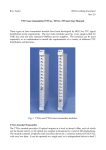
The green Ready LED on the LHCrx front panel (see Fig. 5) indicates when the TTCrx
ASIC in the module is phase locked to the optical signal received from the PCR. Although
the PCR transmitter is normally left running continuously, interruptions for special tests
may occur outside the periods when physics runs are foreseen.
Fig. 5 LHCrx
While a manual Reset switch is provided below the Ready LED, all the LHCrx modules
have now been retrofitted with the most recent version of the TTCrx ASIC which
incorporates a phaselock watchdog circuit. This ensures that the TTCrx PLL will
automatically relock when the transmitter signal is restored after a break.. A reset is also
automatically generated when the TTCmi is initially powered on.
Orbit signal
The ECL Orbit output signal from the LHCrx is simply connected directly to one of the
Inputs of a TTCcf module, the outputs from which are linked to the Orbit Inputs of the
TTCvi modules for each of the trigger partitions. If more than 9 outputs of the Orbit signal
are required, the Input sockets of one or more additional TTCcf modules should be
connected to Outputs of the first module to implement the required fanout. Alternatively
the modules can be daisy-chained as shown in Fig. 4.
Each of the PCR transmitters can be switched to broadcast either the LHC (11.246 kHz) or
the SPS (43.375 kHz) Orbit signal.