1
7
Orbit phase adjustment
Three rotary Orbit phase adjustment switches in the LHCrx module allow the phase of the
master Orbit signal to be brought within the range of the coarse delay adjustments (16
steps of the bunch period of about 25 ns) in the TTCrx ASICs of the local TTC system of
the experiment.
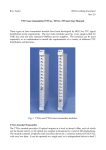
Fig. 6 Orbit phase switches
The phase of the signal can be varied throughout the full LHC period to compensate for
any experiment location around the ring. The least significant switch SW1 (see Fig. 6)
adds delay in steps of the bunch period of about 25 ns. Each step of SW2 corresponds to a
full rotation of SW1 (400 ns) and each step of the most significant switch SW3 to a full
rotation of SW2 (6.4 µs).
The LHC Orbit signal broadcast from the PCR has an arbitrary but invariable phase
relative to the structure of the circulating beams. In fact the timing of the filling of the
LHC and the phasing of the extractor gap will be determined by this signal. Once the
Orbit phase switches have been set for the experiment location they should not require
adjustment again.
40.08 MHz clock signal
The connections for the 40.08 MHz clock distribution are only slightly more complicated.
One of the 40.08 MHz outputs of the LHCrx is connected to the I/P socket of the Clock
Generator module. The Clock Generator module has three 40.08 MHz outputs but in the
TTCmi application only one of these should be used and linked to the REF I/P of the
VCXO-PLL module. When the clock selector switch is in the EXT position the clock
received from the PCR is used, whereas in the INT position the local 40.08 MHz oscillator
is used. After switching from EXT to INT it takes several seconds for the local oscillator to
start up. Note that, since the Clock Generator outputs when the selector switch is in the