1
User’s
Manual
OmniConnect/ISDN
Internet Access Device
Limited Warranty
Allied Telesyn International warrants to the original purchaser that this product is free from
defects in workmanship or materials for a period of one (1) year from the date of purchase.
During the warranty period, and upon proof of purchase, should the product fail due to faulty
workmanship or faulty materials, Allied Telesyn International will, at its discretion, repair or
replace the defective products or components without charge for either parts or labor. Any
replacement will consist of a new or re-manufactured functionally equivalent product of equal
value, and will be solely at the discretion of Allied Telesyn International. This warranty shall
not apply if the product is modified, misused, tampered with, damaged by an act of God, or
subjected to abnormal working conditions. Repair or replacement, as provided under this
warranty is the exclusive and sole remedy of the purchaser. This warranty is in lieu of all
other warranties, express or implied, including any implied warranty of fitness for a particular
use or purpose. Allied Telesyn International shall in no event be held liable for indirect or
consequential damages of any kind or character to the purchaser.
Allied Telesyn International does not assume any liability arising from the application or use
of any products, or software described herein. Neither does it convey any license under any
applicable patent rights. Allied Telesyn International reserves the right to make changes in the
products described herein without notice. This document is subject to change without notice.
Copyright © 1999 by Allied Telesyn International
The contents of this publication may not be reproduced (in any part or as a whole) without the
permission of the publisher.
The information in this publication is believed to be accurate in all respects at the time of
publication, but is subject to change without notice. Allied Telesyn International assumes no
responsibility for any errors or omissions, and disclaims all responsibility for any
consequences resulting from the use of the information included herein. Additionally, Allied
Telesyn International assumes no responsibility for the functioning of undescribed features or
parameters.
OmniConnect, OmniStart and OmniConnect Monitor and combinations thereof are
trademarks of Allied Telesyn International.
TABLE OF CONTENTS
1.
2.
3.
About This Guide ....................................................................... 1
1.1.
Document objectives .................................................................. 1
1.2.
Audience ................................................................................... 1
1.3.
Document organization .............................................................. 1
1.4.
Document Conventions............................................................... 2
Introduction and Overview ....................................................... 3
2.1.
Product
2.1.1.
2.1.2.
2.1.3.
2.1.4.
2.1.5.
2.1.6.
2.1.7.
2.1.8.
2.1.9.
2.1.10.
2.1.11.
2.1.12.
2.1.13.
features ......................................................................... 3
Hardware .................................................................................... 3
OmniStart ................................................................................... 3
OmniConnect Monitor ................................................................ 3
ISDN Basic Rate Interface (BRI)................................................. 3
Advanced voice support .............................................................. 4
Dial-on-demand routing .............................................................. 4
Bandwidth allocation control and bandwidth allocation protocols. 4
DHCP server............................................................................... 5
Network address translation ........................................................ 5
IP address assignment through IPCP............................................ 5
Force dynamically negotiated IP addresses .................................. 5
Data compression........................................................................ 5
Flash firmware upgrade............................................................... 5
2.2.
Security features......................................................................... 6
2.3.
Supported RFCs.......................................................................... 6
2.4.
OmniConnect/ISDN panels......................................................... 6
2.4.1.
Power (green) ............................................................................. 7
2.4.2.
Collision (amber) ........................................................................ 7
2.4.3.
Link (green)................................................................................ 7
2.4.4.
B1 channel (green)...................................................................... 7
2.4.5.
B2 channel (green)...................................................................... 7
2.4.6.
D channel (green)........................................................................ 7
2.4.7.
Phone (analog POTS line) ........................................................... 8
2.4.8.
ST (ISDN S/T)............................................................................ 8
2.4.9.
U (ISDN U) ................................................................................ 8
2.4.10. Console (serial console) .............................................................. 8
2.4.11. Ethernet (four 10Base-T)............................................................. 8
2.4.12. Power (DC 12V) ......................................................................... 8
2.5.
Electrical & physical specifications................................................ 9
Preparing for Installation........................................................ 10
3.1.
Definition of terms.................................................................... 10
3.2.
Helpful
3.2.1.
3.2.2.
3.2.3.
3.2.4.
information .................................................................. 11
Ordering an ISDN BRI line ........................................................11
ISDN ordering codes (IOCs) user guide......................................11
Cabling......................................................................................11
Stacking.....................................................................................11
4.
5.
3.3.
Safety recommendations & maintenance ................................... 12
3.4.
OmniConnect/ISDN package inspection.................................... 12
3.5.
ISDN provisioning information & worksheet ............................... 13
3.5.1.
Data and voice applications over ISDN BRI ............................... 13
3.5.2.
ISDN switch types ..................................................................... 14
3.5.3.
ISDN provisioning with IOCs .................................................... 15
3.5.4.
ISDN provisioning without IOCs ............................................... 17
3.6.
SPIDs ...................................................................................... 19
3.6.1.
Generic SPIDs for NI-1 and NI-2 service ................................... 20
3.6.2.
AT&T 5ESS switch SPIDs ........................................................ 20
3.6.3.
Northern Telecom DMS-100 switch SPIDs ................................ 20
3.7.
Cabling specifications .............................................................. 23
Getting Started .........................................................................25
4.1.
Required connectors, cables and hardware ................................ 25
4.2.
ISDN port connection ............................................................... 25
4.3.
Ethernet (10Base-T) connections ............................................... 26
4.4.
Windows® 95/98/NT configuration & installation ...................... 27
4.4.1.
NIC & network driver installation .............................................. 27
4.4.2.
TCP/IP network installation & configuration.............................. 27
4.4.3.
TCP/IP network configuration ................................................... 27
4.5.
External telephone connection .................................................. 30
4.6.
Power supply connection .......................................................... 30
4.7.
Serial port console connection .................................................. 30
4.8.
Powering on the OmniConnect ................................................. 30
Configuration and Setup ..........................................................31
5.1.
Configuration checklist............................................................. 31
5.2.
OmniStart installation .............................................................. 31
5.3.
OmniStart configuration........................................................... 32
5.4.
OmniStart screens ................................................................... 32
5.4.1.
Welcome screen ........................................................................ 32
5.4.2.
Choose destination location ....................................................... 33
5.4.3.
Multiple router setup.................................................................. 34
5.4.4.
Enter password .......................................................................... 34
5.4.5.
Internet service provider setup ................................................... 35
5.4.6.
ISDN parameters setup .............................................................. 35
5.4.7.
Advanced ISDN configuration ................................................... 36
5.4.8.
ISDN Caller ID directory setup .................................................. 37
5.4.9.
ISDN Add phone number........................................................... 39
5.4.10. ISDN Edit phone number........................................................... 40
5.4.11. ISDN Remove phone number .................................................... 40
5.4.12. ISDN Directory setup ................................................................ 41
5.4.13. ISDN Add phone number........................................................... 42
5.4.14. ISDN Edit phone number........................................................... 43
5.4.15. ISDN Remove phone number .................................................... 43
5.4.16. DNS configuration..................................................................... 44
5.4.17. ISDN Parameter verification ...................................................... 45
6.
7.
8.
Advanced Setup Options ......................................................... 46
6.1.
Advanced setup options ............................................................ 46
6.2.
Performing advanced setup....................................................... 46
6.3.
Advanced setup screens............................................................ 47
6.3.1.
Advanced setup options..............................................................47
6.3.2.
Internet router/filter setup options...............................................48
6.3.3.
Route information ......................................................................48
6.3.4.
Setup Internet filter ....................................................................49
6.3.5.
Advanced filter setup .................................................................50
6.3.6.
OmniNAT setup.........................................................................53
6.3.7.
Static NAT entries......................................................................53
6.3.8.
Static PAT entries ......................................................................54
6.3.9.
LAN IP/DHCP setup options......................................................55
6.3.10. LAN IP configuration ................................................................56
6.3.11. DHCP server include/exclude IP address ....................................57
6.3.12. DHCP server reserve/free IP address ..........................................58
6.3.13. Miscellaneous setup options .......................................................59
6.3.14. WAN IP address setup ...............................................................60
OmniConnect Monitor.............................................................. 61
7.1.
Overview ................................................................................. 61
7.2.
Running OmniConnect Monitor ................................................. 61
7.3.
Diagnostics using OmniConnect Monitor ................................... 61
7.4.
OmniConnect Monitor screens .................................................. 62
7.4.1.
OmniConnect Monitor main screen ............................................62
7.4.2.
Select OmniConnect ..................................................................63
7.4.3.
Configure duration .....................................................................63
7.4.4.
Caller ID....................................................................................63
7.4.5.
Phone extension .........................................................................64
7.4.6.
Diagnostics ................................................................................64
7.4.7.
Firmware upgrade ......................................................................65
Troubleshooting....................................................................... 66
8.1.
Hardware ................................................................................ 66
8.2.
Software .................................................................................. 68
8.3.
ISDN cause codes..................................................................... 70
Appendix A. Glossary ..........................................................................75
Appendix B. Regulatory compliance information ...................................79
Appendix C. Common TCP/UDP port assignments.................................84
1. About This Guide
This section discusses the objectives, audience, organization and conventions of the
OmniConnect/ISDN User’s Manual.
1.1. Document objectives
This publication guides the user through the preparation, installation, configuration and
troubleshooting of the OmniConnect/ISDN access device.
1.2. Audience
This publication is designed for a person with a basic understanding of the Microsoft
Windows® 95/98/NT operating system, Ethernet, standard telephone wiring practices and
networking protocols. It is recommended that the user read through the entire manual prior to
connecting and configuring the new OmniConnect/ISDN device. All acronyms used by the
configuration and installation manuals are defined in Appendix A.
1.3. Document organization
The document is organized as follows:
•
Chapter 1, “About This Guide” discusses the objectives, audience,
organization and conventions of the OmniConnect/ISDN User’s Manual.
•
Chapter 2, “Introduction and Overview” contains an overview of the
OmniConnect feature set, front and rear panel descriptions and the physical
specifications.
•
Chapter 3, “Preparing for Installation” contains safety recommendations,
wiring connection considerations and preparation for ISDN provisioning
and worksheets and guidelines.
•
Chapter 4, “Getting Started” contains step-by-step instructions for
configuring the OmniConnect/ISDN series access devices to operate in
various environments.
•
Chapter 5, “Configuration & Setup” contains instructions on how to
configure the access device for use with the Local Area Network (LAN) and
ISDN providers.
•
Chapter 6, “Advanced Applications” contains instructions on how to
configure advanced applications such as filtering, Network Address
Translation, (NAT) and Dynamic Host Configuration Protocol (DHCP).
•
Chapter 7, “Monitoring OmniConnect/ISDN Operation” contains a
description on the installation and use of the OmniConnect Monitor
application.
•
Chapter 8, “Troubleshooting” contains instructions on troubleshooting any
problems that may occur. In addition, this chapter lists and describes
Integrated Services Digital Network (ISDN) messages that may be sent to
the access device to indicate status.
•
Appendix A, “Glossary” contains a list of all acronyms used as well as their
definition.
OmniConnect / ISDN User’s Manual
Part number 613-10787-00
Page 1
•
Appendix B, “Regulatory Compliance Information” contains the
international regulatory and compliance information for the OmniConnect.
•
Appendix C, “Common TCP/UDP Port Assignments” contains a table of
the port assignments used by a variety of protocols that use both TCP and
UDP.
1.4. Document Conventions
This section describes the conventions used in this publication to convey instructions and
information.
•
Terminal sessions are in courier font.
•
Commands and keywords are in boldface font.
•
User supplied variables are in italic font.
•
Elements in square brackets ( [ ] ) are optional.
•
Alternative, but required keywords are grouped in braces ( { } ) and
separated by a vertical bar ( | ).
NOTE: means reader take note. Notes contain helpful suggestions and references to materials
not contained in this manual.
WARNING statements appear in shaded boxes as shown below:
h
WARNING! This warning symbol means danger. Bodily injury may result if improper
action is taken. Before working on any equipment, proper precautions must be taken.
OmniConnect / ISDN User’s Manual
Part number 613-10787-00
Page 2
2. Introduction and Overview
Congratulations on your purchase of the OmniConnect/ISDN! The OmniConnect series of
access device offers an inexpensive, complete ISDN Internet access solution for the small or
branch office. The OmniConnect/ISDN is ideal for Small Office Branch Office (SOBO)
applications such as network-wide Internet access and making LAN-to-LAN connections to
remote nodes. The OmniConnect/ISDN access device connects Ethernet LANs to other
networks over Integrated Services Digital Network (ISDN) Basic Rate Interface (BRI) lines.
The OmniConnect/ISDN offers TCP/IP routing capability between LAN and WAN ports. In
addition, advanced services such as filtering, DHCP and NAT are available.
This chapter contains the following sections:
•
•
•
•
•
Product features
Security features
Supported internet request for comments (RFCs)
Internet access device front and back panels
Physical specifications
2.1. Product features
This section describes the major features of the OmniConnect/ISDN device.
2.1.1. Hardware
The OmniConnect/ISDN access device features the following hardware interfaces:
•
One ISDN U or S/T ISDN WAN Interface
•
Four 10Base-T Ethernet LAN Ports
•
One Plain Old Telephone System (POTS) analog port
•
One nine pin (DB-9) serial console port
•
One 2.5 mm DC (12V, 1A) power jack
The OmniConnect/ISDN access device also features nine status lights on the front panel to
provide visual indication of the access device operation. The access device itself can be
mounted on either a wall or desktop.
2.1.2. OmniStart
OmniConnect/ISDN remote access / Internet access device software includes OmniStart, a
Graphical User Interface (GUI) utility to assist the user in configuring the access device for
operation.
2.1.3. OmniConnect Monitor
OmniConnect/ISDN device software includes OmniConnect Monitor, a Graphical User
Interface (GUI) utility to assist the user in gathering statistics regarding the access device’s
operation after the configuration process is complete or while the access device is operating.
2.1.4. ISDN Basic Rate Interface (BRI)
OmniConnect/ISDN features either a standard U or S/T interface. (The OmniConnect/ISDN
(U) version uses the U interface and the OmniConnect/ISDN (ST) uses the S/T interface).
OmniConnect / ISDN User’s Manual
Part number 613-10787-00
Page 3
Both interfaces support two independent Bearer (B) channels that can be connected to two
destinations or bundled for one connection to support Bandwidth-On-Demand. In addition to
standard data bearer services, the OmniConnect access devices support Data over Voice
(DOV) service. In some areas, DOV allows the use of inexpensive voice bearer services while
transmitting data, thus saving on long distance and other toll costs.
2.1.5. Advanced voice support
The OmniConnect series of remote access / Internet access devices feature built-in support for
voice call management. OmniConnect equips a small office with the communications
capabilities of a sophisticated corporate office. With OmniConnect/ISDN’s advanced voice
support, small office professionals will present the same professional image as their corporate
office counterparts. By leveraging the full power and speed of ISDN digital telephone service,
the OmniConnect access device provides comprehensive, cost-effective communications for a
small office - including complete voice and data call management. The flexible
OmniConnect/ISDN combines the capabilities of a personal phone system, personal assistant
and ISDN access device into a single, integrated and easy to use product.
OmniConnect/ISDN provides professional call management, call forwarding, distinctive
ringing and caller ID. OmniConnect forwards important callers to a user specified phone
number. When an important customer calls, OmniConnect dials other locations (such as a
cellular phone and an alternative work phone), and connects the caller even when the
OmniConnect user is away from the office. OmniConnect also provides real-time caller ID
support, notifying users of the incoming calls phone number so important calls will not be
missed. In addition, call ringing is distinctive based upon user’s needs.
2.1.6. Dial-on-demand routing
OmniConnect/ISDN includes dial-on-demand routing. Dial-On-Demand ensures that the
OmniConnect will automatically initiates a connection when data traffic is sent from the LAN
to the Internet. This allows LAN users connected to the OmniConnect to dynamically initiate
calls to remote devices across ISDN BRI lines as the need emerges. OmniConnect also
terminates ISDN connections when it senses that there is no demand on the ISDN line from
local users.
2.1.7. Bandwidth allocation control and bandwidth allocation protocols
Bandwidth Allocation Control Protocol (BACP) and the Bandwidth Allocation Protocol
(BAP) define a set of rules that gracefully control dynamic bandwidth allocation by managing
the number of links in a point-to-point protocol (PPP) multi-link bundle. BACP consists of a
network control protocol that negotiates once per PPP multi-link bundle while BAP defines a
set of request and response messages to manage the links.
OmniConnect/ISDN software supports dynamic management of both B channels.
Implementation of BACP and BAP allows OmniConnect access devices to coordinate and
negotiate the actual allocation and de-allocation of the second channel. The parameters are set
using the configuration screen. BACP is only implemented on a BRI interface.
Note: Multi-link PPP has to be negotiated for BACP to be functional.
If a data call is bumped to accommodate a voice call, and BAP negotiation is enforced, the
user might experience a very short audio idle period before a B channel becomes available. In
some cases, the user might not be able to connect the voice call if the peer (the user at the
other end of the data call) declines to terminate the link with the OmniConnect.
OmniConnect / ISDN User’s Manual
Part number 613-10787-00
Page 4
2.1.8. DHCP server
DHCP automates IP addressing and reduces the number of IP addresses a site might require.
The OmniConnect can function as a dynamic host configuration protocol (DHCP) server.
When a DHCP server is enabled and configured, it assigns and manages IP addresses from a
specified address pool to DHCP clients. The options supported by this server are sufficient for
255 TCP/IP clients. If more IP addresses or options are required, a higher-capacity DHCP
server (i.e., Windows NT) could be used.
2.1.9. Network address translation
OmniConnect supports port or Network Address Translation (NAT) allowing a designated
private IP network to communicate with the outside world. When configured, OmniConnect
translates source addresses from an IP private network to a single, global, unique IP address
before forwarding the packets to the outside world. OmniConnect’s implementation of NAT
supports a variety of multimedia applications, games and standard utilities such as telnet, FTP
and HTTP by carefully monitoring each applications use of IP addresses and port numbers. In
addition, the OmniConnect/ISDN allows unsolicited UDP and TCP requests from the Internet
to be routed directly to a single client based solely on port number. This allows applications
that require conversations or connections to be initiated from the Internet such as Diablo,
Microsoft NetMeeting and CuSeeMe to operate correctly. In addition, the
OmniConnect/ISDN allows users to place web servers or email servers on the local LAN, by
allowing holes in NAT. This allows users to access an internal web server that uses a globally
administered IP address from the Internet.
2.1.10. IP address assignment through IPCP
The access device can be assigned an IP address from the remote device using Internet
Protocol Control Protocol (IPCP) address negotiation. The implementation is based on
RFC1332. IPCP address negotiation is on by default in any profile configured for IP routing.
This feature does not support assigning addresses to remote devices.
2.1.11. Force dynamically negotiated IP addresses
When this feature is off, the negotiated IP address is assigned to the standard or the userdefined address. It also tells the software to try any IP address configured for this port in
PPP’s IP address negotiation. When this feature is on and the internal profile does not contain
an address, the negotiated IP address is automatically assigned to the internal profile by the
system. If the Internal profile contains an address, it will be assigned to the user-defined
profile from which the call was initiated.
2.1.12. Data compression
The OmniConnect access device supports data compression using the compression algorithm
QIC-122 standard, Stac LZS. Data compression is a software configuration option that
optimizes the ISDN line bandwidth. Packets are compressed before being sent onto the ISDN
line. After they arrive at their destination, the packets are decompressed and sent on to the
remote LAN.
2.1.13. Flash firmware upgrade
The OmniConnect/ISDN remote access / access device, stores its firmware in FLASH readonly memory (ROM). The FLASH ROM allows the OmniConnect/ISDN access device
firmware to be easily upgraded using the local serial console port. Firmware upgrades may be
downloaded from the OmniConnect web site at http://www.alliedtelesyn.com. All current
configuration parameters for the OmniConnect/ISDN are stored in non-volatile storage. The
configuration parameters can be stored or retrieved via both the serial console port and the
OmniConnect configuration manager.
OmniConnect / ISDN User’s Manual
Part number 613-10787-00
Page 5
2.2. Security features
The OmniConnect/ISDN access device provides the following security features:
•
PPP authentication support, including Password Authentication Protocol
(PAP) and Challenge Handshake Authentication Protocol (CHAP)
•
Password security for local and remote telnet and configuration access
•
TCP, UDP and IP filtering based on source and destination IP addresses,
source and destination ports TCP and UDP ports, and IP packet types.
•
Network Address Translation and Port Address Translation. All local,
private IP addresses are translated to a single, globally unique IP address,
with a unique port number, thus hiding the local station’s addresses and port
numbers from external users. Unless specifically authorized, no externally
generated connection can create a connection with an internal client.
2.3. Supported RFCs
The OmniConnect/ISDN access device supports the following Request For Comments (RFC)
documents:
RFC 1058 - Routing Information Protocol (RIP)
RFC 1332 - PPP Internet Protocol Control Protocol (IPCP)
RFC 1334 - PPP Authentication Protocols
RFC 1541 - Dynamic Host Configuration Protocol (DHCP)
RFC 1552 - PPP Internetwork Packet Exchange
RFC 1570 - PPP Link Control Protocol (LCP) Extensions
RFC 1618 - PPP Over ISDN
RFC 1638 - PPP Bridging Control Protocol (BCP)
RFC 1661 - Point-to-Point Protocol (PPP)
RFC 1717 - PPP Multi-link Protocol (MP)
2.4. OmniConnect/ISDN panels
Figure 2-1, 2-2 and 2-3 show the front and rear panels of the OmniConnect/ISDN access
device. Figure 2-1 shows the front panel, and applies to both versions of the access device.
Figure 2-2 shows the ISDN U interface, and 2-3 shows the ISDN S/T interface version.
OMNI
ISDN
Figure 2-1
Front Panel OmniConnect/ISDN
The Light Emitting Diode (LED) indicators on the front panel of the OmniConnect/ISDN
access device provide visual feedback of the current access device activity. The following
provides a brief description of each of the LEDs, in order, from left to right on the panel.
OmniConnect / ISDN User’s Manual
Part number 613-10787-00
Page 6
2.4.1. Power (green)
When ON, the OmniConnect/ISDN is connected to the 12V DC power source.
OmniConnect/ISDN is powered when it is plugged in, there is no power switch.
2.4.2. Collision (amber)
When FLASHING, the OmniConnect/ISDN is experiencing collisions on the LAN segment to
which it is attached. It is normal for this indicator to flash on occasion.
2.4.3. Link (green)
This LED provides information about the state of the Ethernet 10Base-T connection. There
are four LEDs, one for each of the ports (1-4).
LED State
OFF
FLASHING
ON
Condition
The port is not connected to an active 10Base-T repeater or adapter
The port is receiving data on the associated port
The port is connected to an active 10Base-T repeater or adapter and the link
active
2.4.4. B1 channel (green)
This LED provides information about the state of the ISDN connection. There is a single LED
for each of the B1, B2 and D channels.
LED State
OFF
FLASHING
ON
Condition
The B1 channel is not active
The port is receiving and transmitting data on the B1 channel
The port is connected to an ISDN switch
2.4.5. B2 channel (green)
This LED provides information about the state of the ISDN connection. There is a single LED
for each of the B1, B2 and D channels.
LED State
OFF
FLASHING
ON
Condition
The B2 channel is not active
The port is receiving and transmitting data on the B2 channel
The port is connected to an ISDN switch
2.4.6. D channel (green)
This LED provides information about the state of the ISDN connection. There is a single LED
for each of the B1, B2 and D channels.
LED State
OFF
FLASHING
ON
Condition
The D channel is not active
The port is connecting to an ISDN switch and the Terminal Endpoint
Identifier is being assigned.
The port is connected to an ISDN switch
OmniConnect / ISDN User’s Manual
Part number 613-10787-00
Page 7
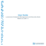
Figure 2-2
Rear Panel OmniConnect/ISDN (U) Remote Access Internet access device
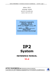
Figure 2-3
Rear Panel OmniConnect/ISDN (ST) Remote Access Internet access device
The connectors and switches on the rear panel of the OmniConnect/ISDN (U) and
OmniConnect/ISDN (ST) allow connections to an external analog phone, ISDN U or ST
interface, serial console, 10Base-T network and DC power. The following provides a brief
description of each of the connectors and switches on both models.
2.4.7. Phone (analog POTS line)
POTS connection to an external telephone, facsimile machine or answering machine. This is a
standard phone jack (RJ-11 style connector).
2.4.8. ST (ISDN S/T)
ISDN line from an external NT1 (RJ-45 connector). This connector is only present on the
OmniConnect/ISDN (ST) model.
2.4.9. U (ISDN U)
ISDN line from telephone company (RJ-45 connector). This connector is only present on the
OmniConnect/ISDN (U) model.
2.4.10. Console (serial console)
Nine pin (DB-9 female) connector to an external RS-232C compatible terminal or computer.
2.4.11. Ethernet (four 10Base-T)
Four Unshielded Twisted Pair (UTP) 10Base-T Ethernet LAN ports (RJ-45 connector). Port 1
is used for connections to other repeaters and PCs. Ports 2-4 are used solely for connections to
PCs. In order to connect the OmniConnect/ISDN access devices to another hub, the MDI
switch at the bottom of the access device must be moved to the ON position. The
OmniConnect/ISDN devices are shipped with the switch in the OFF position, for connection
to PCs. When attempting to move the switch position, please use a non-conductive (plastic)
object.
2.4.12. Power (DC 12V)
DC 12V power supply connection to the OmniConnect/ISDN. This input takes a 12V, 1A
regulated supply.
OmniConnect / ISDN User’s Manual
Part number 613-10787-00
Page 8
2.5. Electrical & physical specifications
The specifications for the OmniConnect/ISDN access device are listed in Table 2-1 below.
Table 2-1 System Specifications OmniConnect/ISDN Internet access device
Description
Design Specification
Height x width x depth
50 x 256 x 152mm
Weight
OmniConnect/ISDN (ST): 1.25 lbs.
OmniConnect/ISDN (U): 1.25 lbs.
Power supply
External 12V DC, 1 AMP
Processor
25MHz 68EN360
Memory
4MB of DRAM
1MB of FLASH
512KB of NVRAM
LAN interface
Four 10Base-T, RJ-45 connectors
WAN interface
One BRI ISDN
OmniConnect/ISDN (ST) – ISDN S/T Interface (RJ-45)
OmniConnect/ISDN (U) – ISDN U Interface (RJ-45)
Telephone interface
POTS RJ-11 connector
Serial console
One 9 pin female (DB-9F) port for connection to DTE
Operating temperature
0° C - 40° C (0° F - 120° F)
Storage temperature
-35° C - 70° C (-30° F - 160° F)
Compliance
FCC Class B requirements and other compliance outlined
in Appendix B
Operating humidity
20% to 95% non-condensing
OmniConnect / ISDN User’s Manual
Part number 613-10787-00
Page 9
3. Preparing for Installation
This chapter provides information required to prepare for installation of the
OmniConnect/ISDN. This chapter should be read carefully to ensure quick, correct
installation of the OmniConnect/ISDN. This chapter contains the following sections:
•
•
•
•
•
•
Definition of terms
Helpful information
Safety recommendations and electromagnetic interference prevention
OmniConnect/ISDN inspection and contents
ISDN provisioning information and worksheet
Cabling specifications
3.1. Definition of terms
The following terms used in this manual are used during the configuration process.
Integrated Services Digital Network (ISDN) Basic Rate Interface (BRI) - A digital
communication medium that operates over existing analog telephone lines provided by the
telephone company. ISDN BRI provides two 64 KBPS Bearer (B) channels for voice and data
and one 16 KBPS D channel for customer and call information. ISDN BRI is usually denoted
as 2B+D.
Service Profile Identifiers (SPIDs) – These are numbers assigned by the ISDN service
provider that identify the ISDN B channels. The SPID format is generally the ISDN telephone
number with several numbers added to it. Depending on the switch type supporting your
ISDN BRI line, your ISDN line might be assigned none, one, or two SPIDs. They are
assigned only in North America.
Directory numbers - The ISDN equivalent of standard telephone numbers. These are the
numbers the access device dials to connect to a remote access device or the numbers that
users dial to connect to a POTS or telephone line attached to the local access device. In order
to use the OmniConnect access device’s powerful call management features to the fullest
extent, it is recommended that multiple Directory Numbers or DNs are for the ISDN BRI line
are ordered along with the line. ISDN BRI lines are generally assigned two local directory
numbers, one for each B channel. However, most Bell Operating Companies and telecom
providers allow up to 8 or 16 Directory Numbers assigned to each line.
Access code - A number that must be dialed preceding the telephone number to dial outside
of a specific telephone system, such as a Centrex system. Examples of this are the ‘9’ that
precedes the telephone number.
Internet Protocol (IP) address - A network address that uniquely identifies a device on an IP
network. This type of address consists of 4 bytes, represented as decimal values, separated by
periods, e.g., 192.168.2.143.
Media Access Control (MAC) address - This 48-bit address is assigned by the device
manufacturer to define the Ethernet address of the device. All OmniConnect access devices
have MAC addresses of the form 00-10-98-xx-xx-xx. Each byte is represented as a
conventional two digit hexadecimal number.
Point-to-Point Protocol (PPP) - A serial protocol defined in RFC 1661 that is used to
provide point-to-point connectivity over serial links.
OmniConnect / ISDN User’s Manual
Part number 613-10787-00
Page 10
Password Authentication Protocol (PAP) - A form of PPP authentication that requires an
exchange of user names and clear-text passwords between two devices. PAP passwords are
sent unencrypted.
Challenge Handshake Authentication Protocol (CHAP) - A form of PPP authentication
that requires an exchange of user names and secrets (encrypted passwords) between two
devices. This security feature is supported on lines using PPP encapsulation. CHAP
passwords are called secrets because they are sent encrypted.
3.2. Helpful information
This section provides information located in this user’s manual that is useful in configuring an
OmniConnect/ISDN remote access / access device.
3.2.1. Ordering an ISDN BRI line
If you have not yet ordered an ISDN BRI line, refer to the worksheet and instructions
provided at the end of this chapter, in the section entitled ISDN Provisioning Worksheet and
Information.
3.2.2. ISDN ordering codes (IOCs) user guide
ISDN is a complex service with many network options. ISDN service is usually ordered using
ISDN ordering codes (IOCs), which simplify the connection and installation of ISDN. If your
local telephone company supports IOCs, see the sub-section entitled ISDN Provisioning with
IOCs. If your local telephone company does not support IOCs, see the sub-section entitled
ISDN Provisioning without IOCs. To help in this process, OmniConnect products support the
most common central office switches in a variety of configurations. IOC Codes EZ-ISDN 1
(Capability U) and Capability S1 are recommended for use in North America with the
OmniConnect/ISDN access device products.
3.2.3. Cabling
The OmniConnect/ISDN access devices use a DB-9 female connector. See the section entitled
Cabling at the end of this chapter for a description on the cable connections
3.2.4. Stacking
You must remove the interlock cap (endstop) at each corner of the unit from every
OmniConnect except the one, which will be on top. From the side of the unit, insert the tip of
a small straight-slot screwdriver into the opening of the interlock cap. Press down on the
screwdriver to pry the cap off.
Install the square rubber bumpers on the base unit.
Note: The LanEdge products will not interlock (stack) properly if the square rubber
bumpers are installed on the interlocking (upper) unit; install these bumpers only on
the base unit.
To interlock the units into a stack, place the base unit on the desktop, then place the next unit
over the base (or stack) and press down on each corner to snap the units together. Repeat until
all units are in the assemblage.
OmniConnect / ISDN User’s Manual
Part number 613-10787-00
Page 11
3.3. Safety recommendations & maintenance
These guidelines must be followed to ensure safety and proper maintenance.
h
•
Do not attempt to remove the top or bottom covers, as you may be exposed
to a shock hazard. Only qualified service personnel should attempt to
remove the covers.
•
Do not place items on top of the OmniConnect/ISDN chassis as these items
may fall into the vents or cover them and prevent proper cooling of the
electronic devices.
•
Do not expose the OmniConnect chassis to rain or excessive moisture to
avoid the risk of shock or permanent damage to the set.
•
Consult a service technician if, after following all instructions in this
manual, the OmniConnect still does not operate correctly.
•
Keep the chassis area clear and dust-free during and after installation.
•
Do not use alcohol or any ammonia-based liquid to clean the OmniConnect
chassis. If necessary, wipe with a dry, lint free cloth.
WARNINGS!
Hazardous voltages are present in the BRI ISDN cable. If you detach the cable, detach
the end away from the OmniConnect first to avoid electrical shock. Hazardous voltages
are also present on the Printed Circuit Board (PCB) in the area of the BRI ISDN RJ-45
connector.
The installation and configuration of the system should not occur during periods of
lightning activity.
Users should not tamper with the ISDN connection.
Ports labeled “10Base-T” and “Console” are safety extra-low voltage (SELV) circuits.
SELV circuits should only be connected to SELV circuits. Do not connect the 10Base-T
connectors (RJ-45) to the BRI ISDN connection as this will result in permanent damage
to the OmniConnect access device.
Ultimate disposal of this product should be handled according to all relevant
international, federal, state, and local regulations.
3.4. OmniConnect/ISDN package inspection
The OmniConnect/ISDN shipkit includes the following items:
•
One OmniConnect/ISDN (ST) or OmniConnect/ISDN (U) internet access
device
•
•
•
One AC power adapter
One OmniConnect/ISDN CD-ROM
One OmniStart Quick Start Guide
OmniConnect / ISDN User’s Manual
Part number 613-10787-00
Page 12
•
•
•
One 10Base-T Ethernet Cable
One analog Telephone Cable
One Warranty Card
Inspect all items for shipping damage. If anything appears damaged, or if problems are
encountered during installation or configuration, contact the local customer service
representative for help. Retain the shipping containers in case the unit needs to be returned.
3.5. ISDN provisioning information & worksheet
This section describes the process of ordering and provisioning an ISDN BRI line to operate
with the OmniConnect/ISDN. Both the ISDN BRI line configuration and the OmniConnect
configuration are dependent upon the ISDN switch that is used by the local telephone
company that is providing the ISDN service. Some local telephone companies allow the use
of ISDN Ordering Codes (IOCs) to simplify ISDN ordering. The ordering codes reflect a
standard set of commonly used configurations for ISDN BRI. If the local telephone company
does not support IOCs, detailed provisioning requirements must be provided. The following
subsections provide describe provisioning the ISDN line for use with the OmniConnect.
•
•
•
•
•
•
Data and Voice Applications over ISDN BRI
ISDN Switch Types
ISDN Provisioning with IOCs
ISDN Provisioning without IOCs
SPIDs
ISDN Provisioning Worksheet
3.5.1. Data and voice applications over ISDN BRI
The OmniConnect/ISDN supports both data and voice applications. Voice applications can be
initiated via the analog telephone port on the OmniConnect access device. If voice capability
is not required, it is possible in some areas to provision the line for data only support. This
may be the preferred option since some ISDN service providers tariff data only lines less than
data and voice lines.
In addition to supporting both voice and data services, the OmniConnect supports Data Over
Voice (DOV) bearer services. In some service areas, provisioning the ISDN line for DOV
bearer service is more inexpensive than data bearer services. DOV is chosen during the ISDN
configuration process.
The use of the analog line requires the use of Additional Call Offering (ACO) services and a
BRI configured for both voice and data applications. ACO allows the user to receive voice
calls when both B channels are being used for data applications. However, regardless of the
type of ISDN service, a voice call cannot be received when there are data calls that have been
made to two different sites. AT&T Custom services (as opposed to NI-1) have an additional
limitation; a voice call cannot be received when both B channels are being used for data.
Outgoing calls are not affected by this limitation since the OmniConnect controls them.
In North America, if the local ISDN connection is supported by an AT&T 5ESS switch, it is
recommended that IOC U/EZ-ISDN 1, IOC V/EZ-ISDN 1A with support for simultaneous
voice and data or IOC S/S1 (if not using an AT&T switch) is ordered for the OmniConnect. In
order to take complete advantage of the advanced call management features of the
OmniConnect access device, it is required that multiple directory numbers (DN’s) or phone
numbers be ordered along with the ISDN line. OmniConnect accommodates multiple phone
OmniConnect / ISDN User’s Manual
Part number 613-10787-00
Page 13
numbers attached to a single phone (each ringing the same phone). This helps the user
respond to incoming calls differently based on the number dialed.
3.5.2. ISDN switch types
The OmniConnect/ISDN supports the switch types described in this section. In North
America, telephone companies primarily provide BRI service with AT&T or Northern
Telecom switches
3.5.2.1.
National ISDN-1
National ISDN-1 (NI-1) BRI switches comply with established National (United States) ISDN
standards. This type of line is supported by AT&T, Northern Telecom and other
manufacturers’ switches. If possible, this type of BRI line should be ordered from the
telephone company service provider since National ISDN-1 switches are guaranteed to offer
Additional Call Offering (ACO). ACO allows the ISDN user to receive an incoming call
when both B channels are in use.
3.5.2.2.
AT&T 5ESS Custom
AT&T 5ESS switches can operate in custom mode, in addition to NI-1 mode (explained
above). Custom mode allows the switch to be configured to operate in either a point-to-point
or a multipoint configuration. Point-to-point configurations support one piece of terminal
equipment on the BRI line and do not require Service Profile Identifiers (SPIDs).
Note: For information on SPIDs, please see the section entitled SPIDs.
It is not possible to support two voice channels simultaneously on a Custom Point-to-Point
link. Therefore, Point-to-Point service only requires the provisioning of one telephone number
for both B channels. Multipoint configurations support multiple pieces of terminal equipment
on the same BRI line and requires SPIDs.
3.5.2.3.
Northern Telecom DMS-100 Custom
Northern Telecom DMS-100 switches support a custom mode used with older terminal
equipment in addition to NI-1.
3.5.2.4.
EURO-ISDN ISDN BRI switch type
The EURO-ISDN switch type, also known as NET-3, is used in Europe and parts of Asia,
including the United Kingdom, France, Germany, Singapore, and Taiwan.
Note: International ISDN BRI lines are not assigned SPIDs; they are typically assigned a
single Directory Number.
There are two basic NET-3 (EuroISDN) implementation variants, termed NET-3 Asia and
NET-3 Europe. In European variations, the Called Party information is transmitted only in the
Q.931 called party information element, whereas in Asian variants, it is permitted (and
sometimes required) to be transmitted in an optional keypad information element.
3.5.2.5.
1TR6 ISDN BRI switch type
The 1TR6 switch type is used in Germany. The 1TR6 lines can be configured for multiple
subscriber numbers, usually referred to as "extended addressing" in Germany. The line is
usually assigned a group of eight sequential directory numbers that can be used for the
OmniConnect / ISDN User’s Manual
Part number 613-10787-00
Page 14
different pieces of terminal equipment used on the BRI line. These numbers are also used for
allocation to the analog telephone port.
Note: International ISDN BRI lines are not assigned SPIDs.
3.5.3. ISDN provisioning with IOCs
ISDN service may be ordered using ISDN Ordering Codes (IOCs) or capability packages. If
the local telephone company supports IOCs, the instructions in this section are applicable. For
the purposes of ordering ISDN lines, capability package designations and IOC codes are
equivalent. Therefore, ordering capability package (IOC) U or EZ-ISDN 1 is equivalent.
The development of ISDN ordering codes (IOCs) simplifies the process of ordering ISDN
service. The ISDN Solutions Group, a consortium of ISDN equipment vendors, service
providers, and Bellcore, established these codes to represent predetermined line
configurations for ISDN Basic Rate service for specific applications. If the local service
provider does not support IOCs, see the section ISDN Provisioning without IOCs.
3.5.3.1.
EZ-ISDN 1 (capability package U)
Ordering EZ-ISDN 1 (Capability Package U) is recommended by the industry for most small
office/small business applications. EZ-ISDN 1 or EZ-1 provides a voice and data BRI line
with a set of supplementary voice features enabled. If EZ-ISDN 1 is not available from the
local service provider, consider the remaining options listed in this document.
Note: For the purposes of ordering the ISDN line, IOC U and EZ-ISDN 1 differ from IOC
V and EZ-ISDN 1A only in that the latter include support for voice mail. If voice mail
is needed, IOC V or EZ-ISDN 1A should be chosen. In all other respects, the two are
identical. The general and supplementary voice features associated with EZ-ISDN 1
are listed below:
3.5.3.1.1. Features
•
2B service
•
Both B channels alternating voice and data
•
Two directory numbers
•
Flexible calling voice features (call forwarding, call transfer, call waiting,
three-way conference calling)
•
Caller ID
Automatic support for call waiting, call conferencing, call transfer and call forwarding applies
only to the first telephone or Directory Number provided (also called Directory Number 1).
For IOC V and EZ-ISDN 1A, voice mail support is automatically included only for the first
DN. Caller ID is supported on both Directory Numbers 1 and 2, but not on the secondary
Directory Numbers (if any). Therefore, if the supplementary voice features are required on the
second or other Directory Numbers, they must be specifically requested.
•
For Call Waiting (as well as Dynamic Bandwidth Allocation) ask for
Additional Call Offering (ACO)
•
For Call Conference (Three-Way Calling) and Call Transfer, ask for
Flexible Call Offering (FCO)
•
For Call Forwarding, ask for Call Forwarding Variable
•
For Voice Mail (if ordering IOC V or EZ-ISDN 1A), ask for Voice Mail
OmniConnect / ISDN User’s Manual
Part number 613-10787-00
Page 15
U/EZ-ISDN 1 does not provide support for simultaneous voice and data on the same
Directory Number, only alternating voice and data is supported. Therefore, if a DN is being
used for a data call, it will be unavailable for an incoming voice call. Incoming calls to the
DN being used will ring busy. However, if the other DN is free, incoming calls will be
allowed on the that DN. Outgoing voice calls are possible since the OmniConnect controls the
outgoing calls for both data and voice. If simultaneous voice and data services are required,
either IOC S or S1 (see below) must be used with Supplementary Voice Services or if the
switch being used is an AT&T 5ESS NI-1 the parameter MAXBCHL must be set to 2.
Neither U/EZ-ISDN 1 nor V/EZ-ISDN 1A provide automatic support for outgoing Caller ID
blocking. To request to have Caller ID blocked added to either DN or both, the user must ask
for Calling Number Privacy. If EZ-ISDN 1 is not available, review the following list and
order ISDN lines from the local service provider using capabilities S or R. Request the
appropriate IOC for the application.
3.5.3.1.2. Capability S (previously generic data M) or S1 (NYNEX)
This ordering code is recommended for applications such as Internet access, BBS and modem
pooling. Capability S allows a maximum of two simultaneous voice and data calls
automatically on both directory numbers. It is the most feature-rich after EZ-ISDN 1 and
supports most voice and data applications. It does not, however support the bulk of the
supplementary features (call conferencing, call transfer, call forwarding and call hold)
supported by EZ-ISDN 1 or IOC U. Capability S1 also provides Additional Call Offering
(ACO) allowing Call Waiting and Dynamic Bandwidth Allocation on both telephone
numbers, whereas U/EZ-ISDN 1 provides ACO automatically on the first DN. Voice mail is
also not supported by S1.
In some areas, ISDN tariffs may warrant the use of ordering codes with fewer features. For
example, in a particular region, there may be additional monthly expense associated with
having voice service on each B channel. If data-only applications are being used, Capability R
(previously Generic Data I) may be more cost-effective than Capability S or S1.
3.5.3.2.
Capability S
• 2B service
• Both B channels simultaneous voice and data
• Two directory numbers
• Caller ID
3.5.3.2.1. Capability R (previously generic data I)
This ordering code is recommended for applications such as Internet access, BBS and modem
pooling. Capability R does not allow voice calls. In some areas, ISDN tariffs may warrant the
use of ordering codes with fewer features. For example, in a particular region, there may be
additional monthly expense associated with having voice service on each B channel. If you
have a data-only application, Capability R (previously Generic Data I) may be more costeffective.
•
•
•
2B service
Both B channels data only
Two directory numbers
OmniConnect / ISDN User’s Manual
Part number 613-10787-00
Page 16
3.5.4. ISDN provisioning without IOCs
This section provides the information required when an ISDN BRI line is ordered without an
IOC. The BRI switch provisions are summarized by switch type (AT&T and DMS-100) for
each of the options that the switches support. When the ISDN BRI line is being ordered
photocopy the appropriate summary for your BRI switch type and attach it to the worksheet or
order form. This will ensure correct provisioning of the ISDN switch.
An explanation of various parameters listed in the provisioning tables are provided following
the AT&T and DMS-100 provisioning tables.
Table 3 –1: AT&T 5ESS Provisioning
Parameter
National ISDN –1
Custom
Multipoint
Custom
Point-to-Point
2–8
2–8
1
2
2
0
STD
MP
PP
B1 Service (B1SERV)
(On Demand) DMD
Note: If voice capability is
not required, replace with
DATA ONLY
(On Demand)
DMD
(On Demand)
DMD
B2 Service (B2 SERV)
(On Demand) DMD
Note: If voice capability is
not required on B2, replace
with DATA ONLY
(On Demand)
DMD
(On Demand)
DMD
2
2
1
Any
Any
Any
Unrestricted
-
-
CSV Limit
2
-
-
Circuit Switched Data (CSD)
2
2
2
Any
Any
Any
No
-
-
Terminal Type (TERMTYP)
A
A
A
Electronic Key System (EKTS)
No
-
-
Directory Numbers (DN)
Service Profile Identifiers (SPIDs)
Data Line Class (DSLCLS)
Circuit Switched Voice Calls (CSV)
CSV Channel (CSVCHL)
CSV Additional Call Offering (CSVACO)
CSD Channel (CSDCHL)
CSD Additional Call Offering (CSDACO)
Note: A blank cell indicates that this configuration option is not applicable for this line
provision
OmniConnect / ISDN User’s Manual
Part number 613-10787-00
Page 17
Table 3 –2: Northern Telecom DMS-100 Provisioning
Parameter
National ISDN –1
Custom Multipoint
2–8
2-8
2
2
Functional
Functional
B Channels
2
2
Protocol Version Control (PVC)
2
1
VVBD/CMD on any B
VVBD/CMD on any B
Dynamic
Dynamic
Release Key
No
No
Additional Call Offering (ACO)
Yes
Yes
EKTS
No
No
1
1
Directory Numbers (DN)
Service Profile Identifiers (SPIDs)
Signaling
Bearer Service
TEI Assignment
Notification Busy Limit
3.5.4.1.
Provisioning parameter definitions
♦ B1 Service (B1SERV)
The bearer service on the B1 line is set to determine whether voice and data or data only
services are required on the B1 line. This should be set to DMD, or On Demand, which
instructs the switch to allow both voice and data on the B1 channel.
♦ B2 Service (B2SERV)
The bearer service on the B2 line is set to determine whether voice and data or data only
services are required on the B2 line. This should be set to DMD, or On Demand, which
instructs the switch to allow both voice and data on the B2 channel.
♦ Circuit Switched Data (CSD)
This parameter sets the total number of B channels that will be used for data services. It
should be set to two so that data services are possible on both B1 and B2 simultaneously.
♦ Circuit Switched Data Channel (CSD CHL)
This parameter sets which bearer channel should be used for the data call. This parameter
should be set to ANY to allow either B channel to be used.
♦ Circuit Switched Data Additional Call Offering (CSD ACO)
This parameter allows incoming data calls when the bearer channel is busy with a data call.
This feature provides notification to the ISDN CPE equipment that a call directed to the CPE
is present at the switch, even though the bearer channel may be busy. This parameter should
be set to U or Unrestricted.
♦ Circuit Switched Data Limit (CSD Limit)
This parameter sets the limit of the number of data calls that may be received at any given
instance. It should be set to two to allow two data calls simultaneously.
♦ Circuit Switched Voice (CSV)
This parameter sets the total number of B channels that will be used for voice services. It
should be set to two so that voice services are possible on both B1 and B2.
OmniConnect / ISDN User’s Manual
Part number 613-10787-00
Page 18
♦ Circuit Switched Voice Channel (CSV CHL)
This parameter sets which bearer channel should be used for the voice call. This parameter
should be set to ANY to allow either B channel to be used.
♦ Circuit Switched Voice Additional Call Offering (CSV ACO)
This parameter allows incoming voice calls when the bearer channel is busy with a data call.
This feature provides notification to the ISDN CPE equipment that a call directed to the CPE
is present at the switch, even though the bearer channel may be busy. This parameter should
be set to U or Unrestricted.
♦ Circuit Switched Voice Limit (CSV Limit)
This parameter sets the limit of the number of voice calls that may be received at any given
instance. It should be set to two to allow two voice calls simultaneously.
♦ Directory Number (DN)
The local phone number(s) associated with the B1 and B2 channels. Typically two DNs are
assigned.
♦ Electronic Key Telephone System (EKTS)
This parameter is used to tell the switch that the CPE equipment is a key system. This
parameter should be set to no.
♦ Terminal Type (TERMTYP)
AT&T has defined terminal types by letters. Terminal Type A is a basic ISDN terminal.
TERMTYP should be set to A.
♦ Service Profile Identifier (SPID)
A SPID is a number that identifies ISDN equipment attached to an ISDN line. In North
America, ISDN lines are typically provisioned with zero, one or two SPIDs.
3.6. SPIDs
A Service Profile Identifier (SPID) is a number that identifies ISDN equipment attached to an
ISDN line. SPIDs are in common use only in North America. In North America, ISDN lines
are provisioned, depending upon the ISDN switch type, with one, two, or zero SPIDs. For
AT&T 5ESS custom switches, no SPID is assigned if the ISDN provider is using a Point-toPoint switch and one SPID is assigned for the Multipoint switch. For Northern Telecom
DMS-100, NI-1 and all NI-1 compliant switches, two SPIDs are usually assigned. All other
switch types do not use SPIDs. When ISDN service is ordered, the ISDN provider assigns the
necessary SPID or SPIDs, which are then used when configuring the OmniConnect/ISDN.
Note:
Normally, it is not necessary to understand the details regarding SPIDs; the
numbers provided by the ISDN provider are simply entered when configuring the
OmniConnect. If, however, the ISDN provider does not provide the necessary SPIDs
or provides SPIDs that are incorrect, the information in the following sections will
aid in providing an explanation to the ISDN provider regarding the SPID
requirements.
An SPID is normally derived from a telephone number for the ISDN BRI line. It may or may
not include the area code, and it may have a special prefix and/or suffix. The SPID formats
used for NI-1, NI-2, AT&T 5ESS and Northern Telecom DMS-100 switches are described in
the following sections.
OmniConnect / ISDN User’s Manual
Part number 613-10787-00
Page 19
3.6.1. Generic SPIDs for NI-1 and NI-2 service
A generic SPID format for National ISDN-1 (NI-1) and National ISDN-2 (NI-2) service is
used by some telephone companies. The format for these generic SPIDs, which are the same
for all switches, is as follows:
aaannnnnnnsstt
•
aaa is the 3-digit area code and nnnnnnn is the 7-digit telephone number for
the ISDN BRI line.
•
ss is the Sharing Terminal Identifier (ID), which a two-digit number from 01 to
32. These two digits are normally 01.
•
tt is a 2-digit code Terminal ID (TID), which is a two-digit number from 01 to
08. These two digits are normally 01.
For example, if the telephone company assigns the telephone numbers 732-555-4549 and
732-555-5343 to the ISDN BRI line, and the IDs and TIDs for both SPIDs are all 01, the
SPIDs are 73255545490101 and 73255553430101.
3.6.2. AT&T 5ESS switch SPIDs
For National ISDN-1 (NI-1) service from an AT&T 5ESS switch, SPIDs are normally in this
format:
01nnnnnnn0tt
•
nnnnnnn is a 7-digit telephone number (not including the area code) of the
ISDN BRI line.
•
tt is a 2-digit Terminal ID code (TID) from 00 to 62.
For example, if the telephone company assigns the telephone numbers 555-4549 and 5555343 to the ISDN BRI line, and 00 is the TID for both numbers, the SPIDs are
015554549000 and 015555343000.
For AT&T Custom Multipoint service, SPIDs are normally in this format:
01nnnnnnn0
•
nnnnnnn is a 7-digit telephone number (not including the area code) of the
ISDN BRI line.
For example, if the telephone company assigns the telephone numbers 555-4549 and 5555343 to the ISDN BRI line, the SPIDs are 0155545490 and 0155553430.
There are no SPIDs for AT&T Custom Point-to-Point service.
3.6.3. Northern Telecom DMS-100 switch SPIDs
For National ISDN-1 (NI-1) service from a Northern Telecom DMS-100 switch, SPIDs are
normally in this format:
aaannnnnnnsstt
•
aaa is the 3-digit area code and nnnnnnn is the 7-digit telephone number for
the ISDN BRI line.
OmniConnect / ISDN User’s Manual
Part number 613-10787-00
Page 20
•
ss is an optional SPID suffix. If present, it is either one digit or two digits. If the
optional suffix is one digit, it must be 0, 1 or 2. A different digit is normally
used for each of the two SPIDs for the ISDN line. If the optional suffix is two
digits, it must be 00, 01 or 02. A different pair of digits is normally used for
each of the two SPIDs for the ISDN line.
•
tt is a 2-digit code from 00 to 62.
For example, if the telephone company assigns the telephone numbers 555-4549 and 5555343 to the ISDN BRI line, 01 and 02 are the SPID suffixes, and 00 is the two-digit code
for both SPIDs, the SPIDs are 40855545490100 and 40855553430200.
For DMS-100 Custom service from a Northern Telecom DMS-100 switch, SPIDs are
normally in this format:
aaannnnnnnss
aaa is the 3-digit area code and nnnnnn is the 7-digit telephone number of the ISDN line.
•
ss is an optional SPID suffix. If present, it is either one digit or two digits. If the
optional suffix is one digit, it must be 0, 1 or 2. A different digit is normally
used for each of the two SPIDs for the ISDN line. If the optional suffix is two
digits, it must be 00, 01 or 02. A different pair of digits is normally used for
each of the two SPIDs for the ISDN line.
For example, if the telephone company assigns the telephone numbers 555-4549 and 5555343 to the ISDN BRI line, and 00 and 01 are the SPID suffixes, the SPIDs are
4085554549 00 and 408555534301.
OmniConnect / ISDN User’s Manual
Part number 613-10787-00
Page 21
ISDN LINE CONFIGURATION REQUEST FORM
NAME:
__________________________________________________
TITLE:
__________________________________________________
COMPANY:
__________________________________________________
ADDRESS:
_______________________________________________
CITY, STATE, ZIP:
COMPANY:
___________________________________________
__________________________________________________
TELEPHONE: __________________________________________________
FACSIMILE:
__________________________________________________
Please provision the ISDN line with the Bellcore Capability Package checked below:
Capability U (EZ-1 or EZ-ISDN1)
Voice and Data w/ ACO
Capability S (or S1)
Voice and Data without ACO
Capability R
Data Only
Please use the following long distance carrier
AT&T
MCI
Sprint
Other____________
_______________________________________________
For Telephone Company Use:
Please fax this sheet, with the information requested below, to the person listed above:
Switch Type:
Custom
National ISDN-1 (NI-1)
AT&T 5ESS Custom (Multipoint)
Northern Telecom DMS-100
AT&T 5ESS Custom(Point-to-Point)
SPID #1
__________________
SPID #2
______________
DN #1
__________________
DN #2
______________
OmniConnect / ISDN User’s Manual
Part number 613-10787-00
Page 22
3.7. Cabling specifications
This section describes the cabling specifications for all the connectors on the rear panel of the
OmniConnect/ISDN access device. Tables describing the pin-outs for the ISDN U, S/T,
Console (DB-9) and POTS line are included in this section.
Table 3-1 ISDN BRI U Interface Pin-out for RJ-45
Pin(s)
Function
1, 2, 3, 6, 7, 8
Not Used
4
U Interface Tip Connection
5
U Interface Ring Connection
Table 3-2 ISDN BRI S/T Interface Pin-out for RJ-45
Pin(s)
Function
1, 2, 7, 8
Not Used
3
S/T Transmit Positive
4
S/T Receive Positive
5
S/T Receive Negative
6
S/T Transmit Negative
ISDN BRI is provided by the Telephone Company from a central office switch to the
customer premises. The ISDN cables can be silver satin cables, though it is recommended that
Category 3 or Category 5 cables are used. The ISDN U and S/T interfaces utilize an 8 pin RJ45 jack. They should be connected to the telephone company line or an external NT1 with a
straight through (untwisted) RJ-45 cable.
Table 3-3 Console Port Pin-out (DB-9 Female)
Pin(s)
Function
1
DCD – Data Carrier Detect Output
2
RXD – Receive Data Output
3
TXD – Transmit Data Input
4
DTR – Data Terminal Ready Input
5
Signal Ground
6
DSR – Data Set Ready Output
7
RTS – Request to Send Input
8
CTS – Clear to Send Output
9
Not Used
The OmniConnect/ISDN access device only uses pins 2, 3 and 5. The rest of the pins are
unused. All input and output references are with respect to the OmniConnect access device.
OmniConnect / ISDN User’s Manual
Part number 613-10787-00
Page 23
Table 3-4 Analog (POTS) Interface Pin-out for RJ-45
Pin(s)
Function
1, 2, 5, 6, 7, 8
Not Used
3
Tip Connection
4
Ring Connection
OmniConnect / ISDN User’s Manual
Part number 613-10787-00
Page 24
4. Getting Started
This chapter describes how to connect the OmniConnect/ISDN series access devices to the
network. In addition, configuration and installation information for a Windows ‘95/NT-based
network is provided. Refer to the diagrams in this chapter and in the previous chapter to
identify the connectors used during installation. The section contains the following:
•
•
•
•
•
•
•
Required connectors, cables and hardware
ISDN port connection
Ethernet connection
Windows ‘95/NT network adapter installation and configuration
External telephone connection
Power connection
Serial console port connection
4.1. Required connectors, cables and hardware
All connectors on the OmniConnect series access devices are on the rear panel of the unit. It
is not normally necessary to connect the serial console port to the OmniConnect unless a
FLASH upgrade is required. The following items will be needed in order to connect the
OmniConnect/ISDN series access device to the network and an external telephone:
•
Power Supply
•
10Base-T Ethernet Cable (RJ-45)
•
ISDN Cable (RJ-45)
•
Telephone Cable (RJ-11)
•
OmniConnect/ISDN Series Internet access device
4.2. ISDN port connection
In North America, OmniConnect/ISDN accesses ISDN lines through a network termination
device (NT-1). The OmniConnect/ISDN (U) access device has a built-in NT-1 capability, so
you can connect this access device directly to the line. If an OmniConnect/ISDN (ST) access
device is being used in North America, then a connection must first be made to an external
NT-1 device and then from the NT-1 device to the ISDN line.
The diagrams below illustrate the connections for both the OmniConnect/ISDN (ST) access
device and the OmniConnect/ISDN (U) access device.
The OmniConnect/ISDN (U) is connected to the ISDN line using the supplied RJ-45 (8-pin)
to RJ-45 (8-pin) cable, as shown in Figure 3-1. It is also possible to use an RJ-11 to RJ-45
cable. The U interface on the OmniConnect access device may also use either an RJ-11 or RJ45 cable for connection to the ISDN network since only the middle two pins are being used.
The OmniConnect/ISDN (ST) access device is connected to the NT-1 device line using the
supplied RJ-45 (8-pin) to RJ-45 (8-pin) cable, as shown in Figure 3-2. For the connection
from the NT-1 device to the ISDN line, it is also possible to use an RJ-11 to RJ-45 or RJ-11 to
RJ-11 cable. The S/T interface on the OmniConnect/ISDN access device may also use an RJ11 connector since only the middle four pins of the jack are used. Using the
OmniConnect / ISDN User’s Manual
Part number 613-10787-00
Page 25
OmniConnect/ISDN (ST) allows a total of 8 ISDN devices to be connected together using the
S/T bus. The S/T bus requires 100-ohm terminations on both ends of the bus.
Note: The OmniConnect/ISDN is pre-configured without the100-ohm terminations. If the
terminator must be changed, please contact technical support for guidance.
h
WARNINGS!
The ISDN jack is to be used for connection to ISDN equipment and lines only. The
connection of a standard phone line or an Ethernet 10Base-T line to the ISDN line may
result in severe damage. The 10Base-T, external POTS and ISDN cables look very much
alike. Care must be used to ensure the correct cable is being utilized.
OmniConnect/ISDN (ST) access devices must not be connected to the ISDN line under
any circumstances.
Console
Ethernet
DC 12V
Figure 3-1: ISDN Port Connections
4.3. Ethernet (10Base-T) connections
Four 10Base-T (Ethernet) twisted-pair connectors on the OmniConnect/ISDN are used to
connect the unit to an Ethernet LAN. Other types of Ethernet cabling (AUI, 10Base-2, etc.)
are also supported through the use of an external converter.
To connect the OmniConnect/ISDN access device to a host computer (Windows or other PC
with an Ethernet or 10Base-T adapter), use the straight through RJ-45 cable provided.
Connections from the OmniConnect/ISDN to repeaters are supported without the use of a
crossover cable. The MDI switch located at the bottom of the access device may be used
switched to the ON position to perform the crossover function internally.
OmniConnect / ISDN User’s Manual
Part number 613-10787-00
Page 26
Connections between the PCs and the OmniConnect access devices are easily verified using
the corresponding Link LEDs provided for each of the Ethernet repeater ports. If the LED is
lit, the connection between the OmniConnect access device and the PC has been established.
4.4. Windows® 95/98/NT configuration & installation
In order to communicate over the Internet using Windows® PCs and the OmniConnect access
device, a 10 MBPS or 10/100 MBPS Ethernet Network Interface Card (NIC) must be installed
in the PC and the TCP/IP protocol be properly configured. This section briefly describes this
procedure. For a definitive description, please refer to the installation manual for the
corresponding NIC as well as the Window® user’s manual. If the NIC has been installed and
TCP/IP configured, the user is urged to skip this sub-section and proceed directly to the
section entitled TCP/IP Network Configuration.
4.4.1. NIC & network driver installation
The NIC should be installed according to the instructions that accompanied the adapter. If the
adapter and operating system support Plug and Play, simply restart Windows®.
Note: Windows ’95 supports Plug and Play. Windows NT 4.0 and below do not support
Plug and Play.
During the boot process, the NIC will be detected automatically and the appropriate network
driver loaded. If the NIC or operating system does not support Plug and Play, the adapter
must be configured manually. This is done by clicking on the Network icon in the Control
Panel window, followed by Add and Adapter. Select the manufacturer and model
appropriate for the NIC and click OK. This should complete network driver installation.
Once the NIC and network driver have been correctly installed, the Link LED on both the
NIC and the OmniConnect access device should be lit.
4.4.2. TCP/IP network installation & configuration
The next step is to install the TCP/IP protocol. This is followed by TCP/IP Network
Configuration.
Note: This manual assumes the use of the TCP/IP protocol provided with the
Windows’95/NT operating systems. For the installation of other, third party TCP/IP
protocols, please refer to the corresponding user’s manual.
Make sure that TCP/IP has been installed by clicking on the Network Icon in the Control
Panel window. The list of installed network components should include TCP/IP. If this is not
the case, click Add, followed by Protocol. Select Microsoft and TCP/IP, followed by OK.
This will add the TCP/IP protocol to the list of installed network components. Next check to
ensure that TCP/IP has been bound to the newly installed NIC by highlighting the installed
adapter and clicking Properties. Check the bindings to ensure that TCP/IP is checked. Click
OK and restart Windows®.
This completes the TCP/IP installation.
4.4.3. TCP/IP network configuration
The OmniConnect/ISDN access devices can be used in both new and existing TCP/IP
networks. In new network installations, the OmniConnect access device can function as a
Dynamic Host Configuration Protocol (DHCP) server. The OmniConnect will assign and
manage all of the attached PC’s IP addresses in the new network from a user specified address
OmniConnect / ISDN User’s Manual
Part number 613-10787-00
Page 27
pool. OmniConnect/ISDN will manage up to a total of 255 IP addresses. If more IP addresses
are required, a commercial DHCP server should be used.
In existing networks, the user has a choice of allowing the OmniConnect access device to
reassign IP addresses for the users, using a mix of DHCP assigned addresses and previously
assigned IP addresses or not utilizing the OmniConnect’s DHCP server. If a commercial
DHCP server is being used, the OmniConnect’s DHCP server should not be utilized.
This sub-section provides guidelines for configuring TCP/IP correctly in each of these
environments.
4.4.3.1.
New installations
In new installations where there is no existing DHCP server, no PCs with pre-configured IP
the OmniConnect’s DHCP server should be used and the TCP/IP configuration parameters on
each PC set as described below.
Note: PCs equipped with Windows ’95, Windows NT and Windows for Workgroups all
support DHCP.
1.
Click the Network icon in the Control Panel Window. Highlight TCP/IP and click
Properties. If TCP/IP appears multiple times, select the instance of TCP/IP that is bound
to an Ethernet networking adapter. If TCP/IP does not appear in the list of installed
components, refer to the previous section on installing TCP/IP.
Note: The TCP/IP Properties tabs may appear in a slightly different order. Simply click on
the corresponding tab to edit that property.
OmniConnect / ISDN User’s Manual
Part number 613-10787-00
Page 28
4.4.3.2.
2.
Set the IP Address to Obtain an IP address automatically.
3.
Set Gateway to be blank.
4.
Set WINS Configuration and DNS Configuration to Disable WINS Resolution and
Disable DNS respectively.
5.
Set Bindings to select Client for Microsoft Networks. It is also permissible to have other
bindings selected.
6.
Leave Advanced with the default parameters untouched.
7.
Click OK twice and restart Windows®.
Existing installations without a DHCP server
In existing installations where TCP/IP has been previously configured and there is no existing
DHCP server, there are two basic sets of options; using each PC’s existing IP address or using
the OmniConnect’s DHCP server to assign (or reassign) each PC’s IP address. In addition,
there may be requirements to allow certain pre-existing global IP addresses to be visible to the
Internet and therefore not assigned by the DHCP server. TCP/IP configuration parameter
settings for these options are described below.
4.4.3.2.1. Use of existing IP addresses
The following procedure must be followed for every PC on the network attached to the
OmniConnect access device.
1.
Click the Network icon in the Control Panel Window. Highlight TCP/IP and click
Properties. If TCP/IP does not appear in the list of installed components, refer to the
previous section on installing TCP/IP.
2.
Set the Gateway address to be the IP address of the OmniConnect. The default IP address
of the OmniConnect access device is 198.162.1.1. If necessary, this should be changed to
reflect the existing IP addressing scheme. In addition, the default subnet mask of the
OmniConnect must be changed to match the existing IP subnet.
3.
Set DNS Configuration to Enable DNS and assign Host, Domain and DNS Server
addresses as provided by the ISP and system administrator.
4.
Leave all other screens untouched.
5.
Click OK twice and restart Windows®.
4.4.3.2.2. Use of the integrated OmniConnect DHCP server
Follow the procedure outlined in the section titled New Installations for all new PCs and for
existing PCs that do not require external visibility of their IP address. For any PC with an
existing IP address that is not capable of DHCP or requires its IP address to be visible across
the OmniConnect access device on the Internet, follow the procedure outlined in the section
titled Use of Existing IP Addresses. In addition, the OmniConnect access device must be
configured to exclude the IP addresses of these PCs during the configuration process. This is
explained in detail in Chapter 5.
4.4.3.3.
Existing installations with a DHCP server
In existing installations where TCP/IP has been previously configured and there is a DHCP
server, the OmniConnect DHCP server must not be used. If the OmniConnect access device is
to be used for Internet access, the existing DHCP server must be configured to provide the
OmniConnect’s IP address as the new gateway address. All other TCP/IP configuration
parameters can remain unchanged.
OmniConnect / ISDN User’s Manual
Part number 613-10787-00
Page 29
4.5. External telephone connection
The OmniConnect/ISDN allows a single connection to a standard POTS (Plain Old Telephone
System) line. Standard analog telephones, facsimile machines, modems, etc., can be
connected to the access device. To connect the analog device to the access device, connect the
telephone cable (provided) to the RJ-11 port (labeled Phone on the rear panel of the access
device as shown in Figure 3-1.
4.6. Power supply connection
Connect the power cable from the 12V, 1A AC adapter to the OmniConnect/ISDN to the port
labeled DC 12V. There is no separate ON/OFF switch on the OmniConnect. When the AC
adapter is plugged in to the wall socket, the unit is powered on and operational.
4.7. Serial port console connection
A DB-9 configuration port labeled Console is located on the rear panel of the OmniConnect.
This port connects to a terminal using a DB-9-to-DB-9 console cable. If the terminal or PC
requires a DB-25 connector, a DB-9-to-DB-25 adapter must be used.
The configuration port is configured as a Data Communications Equipment (DCE) device. It
must be connected to a terminal that is configured as a DTE serial port.
Note: Most COM ports on PCs are configured as DTE and can be directly connected to the
Console port on the OmniConnect access device.
The parameters for the console are 9600 baud, 8 data bits, no parity and 1 stop bit. The
configuration port does not support hardware flow control. The terminal or PC terminal
emulation program must be set to match these parameters. The pin-out for the Console serial
cable is given in Table 2-2.
Note: The Console serial port only uses pins 2, 3 and 5.
4.8. Powering on the OmniConnect
To power-on the OmniConnect, simply attach the supplied AC adapter to any 120V wall
socket. The OmniConnect access device will perform a self-diagnostic test and then be ready
for operation. The LED labeled Power on the front panel should be lit red. The OmniConnect
access devices are now ready for configuration using the configuration manager.
OmniConnect / ISDN User’s Manual
Part number 613-10787-00
Page 30
5. Configuration and Setup
This chapter describes the procedure for configuring OmniConnect/ISDN access devices for
operation. Follow the instructions in this section to configure the access device. This section
contains the following:
•
•
•
•
Configuration Checklist
OmniStart Installation
OmniConnect/ISDN Configuration
OmniStart Screens
5.1. Configuration checklist
The following steps must be completed before attempting to configure the OmniConnect:
•
The ISDN line must be ordered and the SPIDs and Directory Numbers (if
necessary) assigned by the ISDN provider.
•
The ISP login name, password and phone number must be known.
•
The Ethernet 10Base-T network and the ISDN line must be connected to the
OmniConnect access device.
•
The AC adapter must be connected to the OmniConnect access device and
the wall supply.
•
OmniStart must be installed on the PC networked to the
OmniConnect/ISDN access device in accordance with the procedure
described in the following section. In addition, the PC must be connected to
the OmniConnect access device over the Ethernet. It is recommended that
the TCP/IP stack running on the PC be configured to obtain its IP address
from the OmniConnect access device’s DHCP server.
5.2. OmniStart installation
Insert the OmniStart CD into the computer’s CD-ROM drive. The Autorun program will start
automatically, and you will be able to run Setup. Otherwise, you may execute the setup.exe
file on the disk drive from either the Run command within the Windows® 95/98/NT Start
button or by using Windows® Explorer. Follow the instructions on the screen to install the
applications on the computer and to run the configuration application.
Running setup.exe installs the OmniStart configuration program, the help file, two terminal
programs for COM1 and COM2 as well as the OmniConnect Monitor application. In
instances where only the monitor or Caller ID functions are necessary on the local computer
only the monitor program is necessary. To install only the monitor application, execute the
monitor.bat file on the disk drive from either the Run command within the Windows®
95/98/NT Start button or by using Windows® Explorer. This will install the OmniConnect
Monitor application along with the Caller ID function. Monitor.bat should be installed on
every computer where call management and Caller ID functions are required.
OmniConnect / ISDN User’s Manual
Part number 613-10787-00
Page 31
5.3. OmniStart configuration
The installation process automatically executes the OmniStart configuration program after a
series of files have been copied onto the computer. The opening OmniStart Welcome screen
shown below appears. This is the first in a series of screens that are used to install and
configure the OmniConnect access devices. Progression from screen to screen is
accomplished by clicking on the Next> button at the bottom of each screen. Installation and
configuration may be canceled at any point by clicking on the Cancel button.
The OmniStart program has the capability to detect and operate correctly in an environment
where multiple OmniConnect access devices of the same model are present. When the
OmniStart program is invoked, the utility scans the network for connected OmniConnect
access devices. If multiple access devices are detected, OmniStart prompts the user to enter
the IP address of the access device that is to be configured. After the IP address is entered,
execution proceeds as normal.
5.4. OmniStart screens
The OmniStart configuration and setup utility has a number of screens. In most cases the onscreen setup instructions should be followed. This section documents the functionality of the
mandatory screens that the user must fill. The advanced screen functionality is documented in
the next chapter.
5.4.1. Welcome screen
The Welcome screen is the very first screen of the OmniStart configuration and setup
application. This screen contains information about prerequisites for the setup and
configuration program. Please read and follow the instructions on this screen to ensure that
the OmniConnect access device setup proceeds smoothly. Press the Next key to proceed with
the OmniStart setup.
OmniConnect / ISDN User’s Manual
Part number 613-10787-00
Page 32
5.4.2. Choose destination location
The OmniStart setup application copies program and help files to the computer’s hard disk.
These program and help files can be used later to re-run the OmniStart setup and to provide
the user with valuable on-line help information. The default destination drive for the
OmniConnect files is C:\LanEdge\ xxx. This default location may be changed by pressing the
Browse… button and selecting a new location for setup to copy all the OmniStart setup and
configuration files. Clicking the Browse… button brings the following screen, which may be
used to select a new destination. Once a destination directory has been selected, press the
Next > button to proceed with the OmniStart setup and configuration.
The Choose Folder dialog box allows
the selection of a new destination for
the OmniConnect setup files. The new
destination may either be manually
entered or chosen via the directory
tree. Use the pull down Drives menu
to select the destination drive to select
a new directory for installation of the
OmniConnect programs. Press the
OK button once the correct directory
has been selected.
OmniConnect / ISDN User’s Manual
Part number 613-10787-00
Page 33
5.4.3. Multiple router setup
The initial screen displayed
for the OmniConnect/ISDN
setup may be the Multiple
Router Setup screen. If this
screen is displayed it is an
indication that multiple
OmniConnect/ISDN units
have been detected on the
network. Enter the IP address
of the unit that is to be
configured in the IP Address
dialog box. Press Next> to
advance to the next screen.
Press Cancel to exit.
5.4.4. Enter password
The initial screen displayed for the OmniConnect/ISDN configuration is the Enter Password
screen. Access to the OmniConnect configuration utility is protected by a password. The
default password is Omni. Enter Omni into the dialog box titled Password and press Enter or
Next> to advance to the next screen. To change the password from the default value, click the
check box ‘Select this box to change the password’ and then enter the new password in the
New Password and Confirm New Password dialog boxes and press Next>. This will change
t
h
e
p
a
s
s
w
o
r
d
t
o
t
h
e
n
e
w
v
OmniConnect / ISDN User’s Manual
Part number 613-10787-00
Page 34
alue. The maximum length of the password string is 15 characters. Passwords can contain any
alphanumeric character. Pressing Cancel will terminate the OmniStart installation.
5.4.5. Internet service provider setup
The Internet Service Provider
Setup screen is used to enter the
Internet Service Provider (ISP)
login and password
information. The Internet
Service Provider (ISP) should
have already provided a login
name, password and phone
number. Enter the login
information provided in this
screen. The OmniConnect
access device will use this
information to establish a
connection with the Internet
Service Provider.
The ISP will also provide either
one or two phone numbers that
are used to access the ISP. If
only one phone number is
provided, leave the box
Alternate Phone Number
blank and proceed to the next
screen. Remember to enter any
numbers required to access an
outside area code or city code.
5.4.6. ISDN parameters setup
The ISDN Parameters Screen is used to enter ISDN configuration information. When an
ISDN line is ordered, the ISDN dial-tone provider assigns an ISDN switch for the ISDN
connection. The ISDN dial tone provider will also issue switch software configuration and the
ISDN phone numbers and SPID Numbers. Use this screen to enter all these parameters.
Note: In certain cases, less than two SPIDs or ISDN Phone Numbers will be provided.
Refer to the chapter entitled Preparing for Installation for further information on
ISDN configuration.
OmniConnect / ISDN User’s Manual
Part number 613-10787-00
Page 35
First, use the ISDN Switch Type pull-down menu to select the ISDN Switch Type. If the
switch type assigned by the service provider is not listed, please select the Others option.
Next, select the Switch Software Type. The setup program highlights only valid Switch
Software Types based on the ISDN Switch Type. Also enter the ISDN phone numbers and
ISDN SPID numbers, if applicable, into the edit boxes located at the bottom of this screen.
The Enable Data Over Voice (DOV) dialog box should be checked if the ISDN line is
provisioned for Data Over Voice. If the Disable Data Over Voice (Data Only) dialog box is
checked, the OmniConnect access device will request Data Only bearer services. The default
is Enable Data Over Voice.
Once this information has been entered, pressing the Next > button will advance the setup
process to the next screen. Pressing the Advanced >>> button will allow the setting of
advanced ISDN parameters. If the ISDN link has not been configured or all the information
on this screen is not available, the setup process may be canceled by pressing the Cancel
button. At any time, it is possible to return to the previous setup screen by pressing the <Back
button.
In order to use the advanced calling features such as Call Management, Distinctive Ringing,
Call Forwarding or Caller ID, either the ISDN Directory button or the Caller ID button must
be pressed and information on these screens entered. This will advance the user to the screens
where additional ISDN Directory Numbers and Caller ID information can be entered.
5.4.7. Advanced ISDN configuration
The Advanced ISDN Configuration screen may be reached by pressing the Advanced >>>
button located on the ISDN Parameter Setup screen. This screen is used to enter Advanced
ISDN Configuration parameters.
Entering a number in the Disconnect ISDN after <Number> Seconds dialog box sets the
ISDN Inactivity Timer. The OmniConnect access device uses this value to monitor activity on
the ISDN link and disconnects the ISDN connection after this timer expires. The timer is set
OmniConnect / ISDN User’s Manual
Part number 613-10787-00
Page 36
to expire after a number of seconds have passed without any data traffic. If you set this timer
to zero, then the ISDN connection will never be disconnected.
The 2nd ISDN bearer channel (B2 channel) may either be enabled or disabled. We recommend
that the OmniConnect/ISDN series access device dynamically use the B2 or 2nd channel by
selecting the Dynamically check box. If, however, the 2nd ISDN channel is never to be used,
it may be disabled by selecting the Never check box. When the Never check box is selected,
the OmniConnect access device will not enable the B2 channel (even when the traffic
conditions require it to use the 2nd ISDN channel). The 2nd ISDN channel may be enabled, on
a permanent basis, by selecting the Always check box. This forces access device to dial using
both ISDN channels all the time. Both the B1 and B2 channels will always be connected when
this option is selected.
The ISDN Channel Speed parameter is used to set the rate at which ISDN data calls are
connected to the ISP. Voice calls are always connected at 64 KBPS regardless of the setting
of this parameter. Use the check boxes to choose between Auto, 64 KBPS or 56 KBPS.
When Auto is chosen, connections to the ISP are attempted at 64 KBPS and then in most
instances retried at 56 KBPS. There are certain circumstances in which 56 KBPS connections
are not attempted and therefore 56 KBPS connections may not complete when set to Auto. In
these cases, the parameter should be set to 56 KBPS.
The Analog Phone Setup configuration option is used to control the flow of analog calls.
Incoming and outgoing analog calls may be allowed or prohibited by either selecting the
Allow Analog Calls or Disable Analog Calls setup options. If the Allow Analog Calls
option is selected, the ISDN Channel (B1 or B2) may be further specified to carry the analog
call. The Auto selection lets the OmniConnect access device decide which ISDN channel to
use for analog calls based on the traffic patterns and usage. This, however, can be forced to a
certain ISDN channel for voice calls by selecting B1 or B2 channel.
Finally, the Digital Voice Coding parameter sets the voice-coding standard used to
communicate with the Central Office switch during voice telephone calls. In North America
and Taiwan a type of PCM encoding known as µlaw is used. In Europe and Asia, A-law PCM
encoding is used. Choose the correct encoding for the area in which the OmniConnect/ISDN
is being used.
Press Next> to advance to the next screen, or press Cancel to exit.
5.4.8. ISDN Caller ID directory setup
The ISDN Caller ID
Directory Setup screen
is used to add, edit and
remove ISDN Caller
ID entries. Caller ID
information that is
received during an
incoming call is
displayed by the
OmniConnect Monitor
application. See the
section entitled
OmniConnect Monitor
for further details. In
addition, Caller ID
information is used by
the OmniConnect
access device to
perform call
OmniConnect / ISDN User’s Manual
Part number 613-10787-00
Page 37
management duties such as call forwarding, call assignment and distinctive ringing. Based
upon the information provided on this screen and the incoming Caller ID, the extension
associated with the incoming phone number is rung or forwarded. The OmniConnect access
devices allow a total of 16 Caller ID settings to be configured. Caller ID configuration is
completely flexible; 16 incoming calling phone numbers may be assigned to any number of
POTS lines or assigned to a single POTS line. The OmniConnect/ISDN access device
supports a single POTS line and therefore all available Caller IDs are assigned to this single
line. The OmniConnect access device refers to each POTS line as an extension. The first
POTS line is assigned Extension 1.
The ISDN Caller ID Directory Setup screen displays a list of all available phone numbers that
have been added and the parameters associated with each number. For each entry listed, the
user is able to set four parameters:
•
EXT# - the extension number to dial (this defaults to 1 for the
OmniConnect/ISDN and is the only possible option for this product.
•
RING – the type of ring (Normal, Personal, Urgent and Off)
•
Normal – Standard United States ring – 2 seconds on, 4 seconds off
•
Personal – Standard International Ring – 0.8 seconds on, 0.4 seconds off,
0.8 seconds on, 4 seconds off
•
Urgent - 0.8 seconds on, 0.4 seconds off, 0.8 seconds on – repeating
indefinitely.
•
Off – No ring
•
FORWARD – Whether or not to forward the call.
•
FORWARD# - The number to which the call should be forwarded.
To add Caller ID information, click on the Add button to advance to the ISDN Add Phone
Number screen. To edit information, click the Edit button to advance to the ISDN Edit Phone
Number screen. To remove an entry, click Remove to advance to the ISDN Remove Phone
Number screen. This will advance the user to the respective screens.
OmniConnect / ISDN User’s Manual
Part number 613-10787-00
Page 38
5.4.9. ISDN Add phone number
The ISDN Add Phone Number screen is used to add a Caller ID phone number. When an
incoming phone call with the phone number entered on the ISDN Add Phone Number screen
is detected, the Extension Number, Ring Type and Call Forwarding parameters set in this
screen are used.
Enter the phone number of the person to be
tracked in the Phone Number dialog box.
Enter a descriptive term (e.g., Mother) in
the dialog box marked Description. This
description will be used by the
OmniConnect Monitor application to
display this incoming call information.
Next, choose the Extension Number to be
rung when the Caller ID information from
the incoming call matches the phone
number. (For the OmniConnect/ISDN, this
will always be 1, since there is only 1
POTS line).
Choose a RING Type from the selection in the pick list. The options are:
•
Normal – Standard United States ring – 2 seconds on 4 seconds off
•
Personal – Standard European Ring – 0.8 seconds on, 0.4 seconds off, 0.8
seconds on, 4 seconds off
•
Urgent - 0.8 seconds on, 0.4 seconds off, 0.8 seconds on – repeats
•
Off – No ring
Lastly, determine whether this call is to be forwarded or not. If the call is to be forwarded,
choose either Send All or After 4 Rings. In the case of Send All, all incoming calls from this
caller ID will be forwarded immediately. In such cases, the phone will briefly ring, but the
user will be unable to pick up the phone. In the case of After 4 Rings, the call will be
forwarded to the number specified in Forward Destination after four rings.
Note: The complete phone number including any international or long distance prefixes
must be entered in this field.
Once you have finished entering the information, click Next> to advance to the next screen.
OmniConnect / ISDN User’s Manual
Part number 613-10787-00
Page 39
5.4.10. ISDN Edit phone number
The ISDN Edit Phone Number screen is used
to edit a Caller ID phone number.
Use one of the available phone numbers of
the person to be tracked in the Phone
Number dialog box by selecting from the
pull-down menu. Then change any of the
dialog boxes or settings for that phone
number. All the parameter settings and
choices are exactly the same as described
previously for the ISDN Add Phone Number
screen. Then select Next> to complete
editing this entry in the Caller ID list and
advance to the next screen.
5.4.11. ISDN Remove phone number
The ISDN Remove Phone Number screen is used to remove a Caller ID phone number.
Select one of the available phone
numbers of the person to be tracked in
the Phone Number dialog box by
using from the pick list. Then select
Next> to remove this entry from the
Caller ID list and advance to the next
screen.
OmniConnect / ISDN User’s Manual
Part number 613-10787-00
Page 40
5.4.12. ISDN Directory setup
The ISDN Directory Number Setup screen is used to add, edit and remove ISDN Directory
Number (phone number) entries. ISDN BRI lines allow the user to choose multiple Directory
numbers per line. OmniConnect access devices allow a total of 8 DNs to be configured.
Directory Number configuration is completely flexible; all available DNs may be assigned to
any number of POTS lines or assigned to a single POTS line. The OmniConnect/ISDN access
device supports a single POTS line and therefore all available DNs are assigned to this single
line. The OmniConnect access device refers to each POTS line as an extension. The first
POTS line is assigned Extension 1. Directory Number information is used by the
OmniConnect to perform call management duties such as call forwarding and distinctive
ringing. Based upon the information provided on this screen and the incoming caller ID, the
extension associated with the incoming phone number is rung or forwarded to a separate
number. For example, if the OmniConnect/ISDN access device detects an incoming call to a
particular phone number assigned to 4085552121, as shown in the illustration above,
extension 1 will be rung using a normal ring and call forwarding will be ignored.
Note: The OmniConnect access devices give priority to the Caller ID settings. If an
incoming call matches any of the Caller ID settings, they will be used to determine
the ring status and forwarding status of the call. Only if the Caller ID is not
matched, will the ISDN Directory Number settings be used. A single entry for every
assigned DN must be present on this screen.
The ISDN Directory Setup screen displays a list of all available phone numbers that have
been added and the parameters associated with each number. The two phone numbers that are
usually entered in the ISDN configuration screens are automatically entered here and default
to Normal ringing on extension 1, with call forwarding off.
As with the Caller ID setup, for each entry listed, the user is able to set four parameters:
•
EXT# - the extension number to dial (this defaults to 1 for the
OmniConnect/ISDN and is the only possible option for this product.
OmniConnect / ISDN User’s Manual
Part number 613-10787-00
Page 41
•
RING – the type of ring (Normal, Personal, Urgent and Off)
Normal – Standard United States ring – 2 seconds on 4 seconds off
Personal – Standard European Ring – 0.8 seconds on, 0.4 seconds off, 0.8
seconds on, 4 seconds off
Urgent - 0.8 seconds on, 0.4 seconds off, 0.8 seconds on – repeats
Off – No ring
•
FORWARD – Whether or not to forward the call.
•
FORWARD# - The number to which the call should be forwarded.
To enter additional Directory Numbers, click on the Add button. To edit existing Directory
Number information, click the Edit button. To remove a DN entry, click Remove. This will
advance the user to the respective screens.
5.4.13. ISDN Add phone number
The ISDN Add Phone Number screen is used to add a Directory phone number. When an
incoming phone call with this phone number is detected, the Extension Number, Ring Type
and Call Forwarding parameters set in this screen are used.
Enter one of the Directory Numbers assigned
to the ISDN BRI line in the Phone Number
dialog box. Enter a descriptive term (e.g.,
President) in the dialog box marked
Description. Next, choose the Extension
Number to be rung when the Caller ID
information from the incoming call matches
the phone number. (In the case of the
OmniConnect/ISDN products, this will always
be 1, since there is only 1 POTS line).
Choose a RING Type from the selection in the pick list. The options are:
•
Normal – Standard United States ring – 2 seconds on 4 seconds off
•
Personal – Standard European Ring – 0.8 seconds on, 0.4 seconds off, 0.8
seconds on, 4 seconds off
•
Urgent - 0.8 seconds on, 0.4 seconds off, 0.8 seconds on – repeats
•
Off – No ring
Lastly, determine whether this call is to be forwarded or not. If the call is to be forwarded,
choose either Send All or After 4 Rings. In the case of Send All, all incoming calls destined
for this phone number will be forwarded immediately, (the phone will briefly ring, but the
OmniConnect / ISDN User’s Manual
Part number 613-10787-00
Page 42
user will be unable to pick up the phone). In the case of After 4 Rings, the call will be
forwarded to the number specified in Forward Destination after four rings.
Note: The complete phone number, including any international or long distance prefixes,
must be entered in this field.
Once the user has completed entering the information, Next> should be clicked to advance to
the next screen.
5.4.14. ISDN Edit phone number
The ISDN Edit Phone Number screen is used to
edit a DN or phone number.
Use one of the available phone numbers in the
Phone Number dialog box by selecting from the
pick list. Then change any of the dialog boxes or
settings for that phone number. All the parameter
settings and choices are exactly the same as
described previously for the ISDN Add Phone
Number screen. Then select Next> to complete
editing this entry from the Directory Number list
and advance to the next screen.
5.4.15. ISDN Remove phone
number
The ISDN Remove Phone Number screen is
used to remove a DN or phone number.
Select one of the available phone numbers of the
person to be tracked in the Phone Number
dialog box by using the pick list. Then select
Next> to remove this entry from the Directory
Number list and advance to the next screen.
OmniConnect / ISDN User’s Manual
Part number 613-10787-00
Page 43
5.4.16. DNS configuration
The DNS Configuration screen displays the Domain Name Server (DNS) configuration
information. Use this screen to enter the domain name and IP address of the DNS Server used
by the ISP. This information should have been provided by the ISP. This information is
required only if the DHCP server is being utilized. The DHCP server will provide the DNS
information collected from this screen to all the DHCP clients. Selecting the Disable DHCP
Server option will disable the DHCP Server. When the Disable DHCP Server is selected, the
DNS Configuration information is not required and may be left blank.
The DNS configuration that should be entered here includes the Domain Name and the
Domain Name Server IP addresses. Once these have been entered this information press the
Next > button to proceed to the next screen.
OmniConnect / ISDN User’s Manual
Part number 613-10787-00
Page 44
5.4.17. ISDN Parameter verification
The ISDN Parameter Verification screens are used to verify the configuration of the ISDN
line, ISDN switch settings, the ISP information and the DNS information. Each of these
parameters are checked for the ISDN line. If there is a failure an ‘x’ is displayed next to the
failing item and if the configuration is correct, a check mark is displayed.
ISDN Configuration checks to see if the ISDN line correctly connected to a live ISDN line
and the ISDN switch parameter settings (switch type, Directory Number and SPID) are
correct. If any of these are not true, ISDN Configuration returns a failure. ISP Configuration
checks to see if the ISP information (login, password and phone number) is correct and a
login is possible. If any of these are not correct, this test returns a failure. Lastly, DNS
Configuration checks the DNS server address that is entered in the DNS screen. If this is
incorrect, this test returns a failure.
Normally, this concludes the setup process. Press the EXIT button on the next screen to exit
the setup program. The OmniConnect access device is ready for use!
OmniConnect / ISDN User’s Manual
Part number 613-10787-00
Page 45
6. Advanced Setup Options
This chapter describes the procedure for configuration of the OmniConnect/ISDN access
devices for advanced operation. Follow the instructions in this section to configure advanced
options of the OmniConnect access device. This section contains the following:
•
•
•
Advanced setup options
Performing advanced setup
Advanced setup screens
6.1. Advanced setup options
The Advanced Setup Options allow the configuration of certain advanced options available in
OmniConnect/ISDN access device. These advanced setup options are:
•
•
•
Internet access device, Filter and OmniNAT option
DHCP Server Configuration
Miscellaneous Setup Options
The advanced options allow the configuration of the OmniConnect/ISDN access device, filter
and OmniNAT tables.
The OmniConnect static route table allows the configuration of any special route table entries
into the OmniConnect access device configuration. Once the route table is correctly
configured, the OmniConnect access device will perform the routing functions as specified in
the route table entry. The detailed description of the OmniConnect route table entry screen is
described in the Advanced Setup Screens section below.
The OmniConnect Filter advanced setup option allows the definition of various Internet
traffic filter criteria. Access to the Internet may be selectively disabled or enabled, or selective
protocols or applications may be filtered using the OmniConnect access device. The powerful
filtering mechanism provided by the OmniConnect access device allows the user to construct
a secure firewall. In addition, the filtering features of the access device may be used to disable
outgoing keep-alive messages sent by various applications that unnecessarily waste
bandwidth. These procedures are described in the filtering section.
The OmniNAT (Network Address Translation) function allows the use of a single user
Internet Service Provider (ISP) account for multiple users. This advanced feature may be
turned on or off using the OmniNAT advanced setup option. OmniNAT may be configured to
disable OmniNAT for certain machines located on your network. These procedures are
described in the OmniNAT section.
The OmniConnect/ISDN access device features a built-in DHCP server. All DHCP related
options are configured using the DHCP Server advanced setup option.
The miscellaneous setup options allows the configuration of various other advanced
functions. These functions are documented in the advanced setup screens below.
6.2. Performing advanced setup
The OmniStart utility asks the user to enter some mandatory configuration information before
advancing to the Advanced Setup Options screen. At this point all the advanced setup options
OmniConnect / ISDN User’s Manual
Part number 613-10787-00
Page 46
are available by pressing the appropriate buttons. Once the advanced setup is complete,
pressing the EXIT button on the Advanced Setup screen exits the OmniStart utility.
6.3. Advanced setup screens
The OmniStart configuration and setup utility has a number of advanced setup screens. The
advanced screen functionality is documented in this section of the OmniConnect/ISDN user’s
manual.
6.3.1. Advanced setup options
Once the user has reached the Advanced Setup Options screen, all the required parameters for
the OmniConnect access device have been configured. The various options located on this
screen may be used to further setup various OmniConnect advanced options.
Use the first button to setup Internet access device, Filter or Network Address Translation
(NAT) features of OmniConnect.
The DHCP Parameters and the LAN IP address and Gateway IP address may be configured
by pressing the second button.
Selecting the Set Miscellaneous Parameters button can configure various Miscellaneous
Parameters for the OmniConnect access device. These Miscellaneous parameters include
resetting the OmniConnect Internet access device, Resetting the default parameters of
OmniConnect and setting the WAN IP addresses of OmniConnect.
Complete the OmniConnect access device setup by pressing the FINISH button. Selecting the
OmniConnect Configuration option icon installed in the OmniConnect Folder can restart the
OmniConnect setup.
OmniConnect / ISDN User’s Manual
Part number 613-10787-00
Page 47
6.3.2. Internet router/filter setup options
The Internet Router/Filter Setup
Options screen allows the user
to navigate to one of the
advanced setup options screens.
The user may configure the
OmniConnect static access
device table entries by selecting
the Setup Internet access device
Table button. The advanced
filter functions of OmniConnect
access device may be reached
by pressing the Setup Filter
Table button.
The Network Address
Translation (NAT) setup screen
may be reached by pressing the
Setup OmniNAT Parameters
button. To move to the previous
screen, press either <Back or
Next>. Press Cancel to exit.
6.3.3. Route information
The OmniConnect access device’s default configuration is to forward, or route, any packets
from the 10Base-T LAN to the BRI ISDN. Any inbound packets at the Ethernet interfaces
that do not match the local subnet mask (usually 192.168.1.X) will be automatically
forwarded to the WAN interface. Since the WAN interface is a point-to-point PPP link and
there is only one such link, it is not normally necessary to use a route table; all packets that
need to be routed are sent
over the single WAN link.
If, however, there is a
need to configure the
OmniConnect access
device to forward or route
IP packets destined to a
particular host or network
differently, the Route
Information screen should
be used. The Route
Information screen allows
the configuration of the
OmniConnect to forward
incoming packets to a
next-hop gateway that is
directly attached to
10Base-T LAN subnet.
The Route Information screen is used to enter the static route table entries. The OmniConnect
supports up to 8 entries in the static route table. Select one of the Route Numbers by using the
pull down menu. Enable or Disable that static route by selecting either the Route Enable or
OmniConnect / ISDN User’s Manual
Part number 613-10787-00
Page 48
Route Disable check boxes. Make this static route entry permanent or temporary by selecting
one of these options from the Route Type pull down menu. The temporary route entries are
lost when the OmniConnect access device is powered down. The Permanent route entries are
stored in the FLASH memory located in the OmniConnect. The permanent router table entries
are not lost between power recycles.
The destination IP address of the host or network for which the static route is configured is
entered in the IP Address field. The Next Hop Gateway or access device to which packets that
use this static route should be sent must be inserted in the Gateway (Interface) field. The Host
or Network check boxes are used to distinguish between a static route entry that defines a
route to a particular host or to a complete IP subnet. If an IP subnet static route is being
defined, it is acceptable to leave portions of the IP Address entry at zero.
6.3.4. Setup Internet filter
The OmniConnect access device allows the user to configure a powerful set of filters for
Internet traffic. These filters may be used for the purposes of configuring an Internet firewall,
to allow access to certain applications or to restrict access to a certain group of users. The
Setup Internet Filter screen is used to define these filters.
The Enable Internet Access control enables Internet traffic to and from the OmniConnect
access device. The Disable Internet Access control disables all access to the Internet. If the
user selects the Disable Internet Access button, all traffic to and from Internet will be blocked.
OmniConnect / ISDN User’s Manual
Part number 613-10787-00
Page 49
OmniConnect filtering also allows the selective disabling and enabling of certain Internet
applications such as WWW or FTP. Once Internet access is enabled, applications may be
selectively disabled or enabled by selecting or de-selecting the corresponding check boxes.
They are:
Web access (WWW):
By selecting the Allow Web Access (WWW) check box, all
incoming and outgoing Web access messages will be allowed by
the OmniConnect filters. To disable Web Access, de-select Allow
Web Access check box and all the OmniConnect filters will block
all Web access messages.
File transfers (FTP):
Selecting Allow File Transfers check box allows users to perform
file transfer functions over the Internet. De-selecting this option
may block file transfers.
Mail access (SMTP):
Control the mail messages to and from the Internet by selecting or
de-selecting this check box.
File system mounting:
The Network File System (NFS) protocol allows users to share
complete file systems with other computers on Internet. This
feature may be allowed or blocked by controlling this option check
box.
Remote login (telnet):
Internet TCP-IP protocol suite has a remote login protocol, which
allows computers to login into other computers remotely. This
protocol may be blocked or allowed by selecting or de-selecting
this feature.
Appendix C contains a list of commonly used TCP and UDP port numbers and their
applications.
6.3.5. Advanced filter setup
This screen is used to configure advanced filtering options for the OmniConnect/ISDN access
device. A total of 10 advanced filter sets (numbered from 1 to 10) may be configured.
Selection of one of the ten filters is accomplished by using the pull down menu labeled Filter
Number. Once the correct filter number has been selected, the various filter options for that
particular filter number may be configured.
Note: Filter 1 has been preset to filter NetBIOS requests that may be causing the
OmniConnect access device to dial erroneously. To enable this filter, select the
Filter Enabled check box. See the troubleshooting section for more detail.
The Filter Direction indicates the direction in which the filter will be applied. The
OUTGOING direction is for packets flowing from the LAN (10Base-T Ethernet) to WAN
(ISDN) interface. The INCOMING direction is for packets flowing from WAN (ISDN)
interface to the LAN (10Base-T Ethernet). The allowed values are INCOMING, OUTGOING
or BOTH
The Filter Enabled box should be checked to enable the filtering for the particular Filter
Number. If the Filter Enabled box is checked, filtering is enabled. Enabling a filter causes
packets matching the filtering criteria to be dropped or forwarded, depending upon the state of
the Forward Enabled check box. If the Filter Enabled box is not checked, all the windows in
this screen with the exception of the Filtern Number are disabled.
The Forward Enabled parameter should be checked to enable forwarding. If the Forward
Enabled parameter is checked, then packets matching the filter criteria are forwarded. If the
OmniConnect / ISDN User’s Manual
Part number 613-10787-00
Page 50
Forward Enabled parameter is left blank, then packets matching the filter criteria are
discarded.
Protocol Type contains the protocol used for this filter. The allowed values are IGNORE, IP,
ICMP, IGMP, GGP, TCP, PUP, and UDP
The TCP Start of Connection (TCPSOC) indicates if the filter is applied to TCP SYN
(connection request) packets. The three allowed options are IGNORE, YES and NO. The
IGNORE option instructs the filter to ignore TCPSOC. The YES option instructs the filter to
match only the initiating packet in a TCP connection. The NO option instructs the filter to
match any TCP packet except the initiating packet in a TCP connection.
ICMP Code has the following options. Echo Reply, Dest Unreachable, Src Quench, Redirect,
Echo Request, Time Exceeded, Parameter Problem, Timestamp Request, Timestamp Reply,
Info Request, Info Reply, Addr Mask Request, Addr Mask Reply, and Ignore
ICMP Codes are defined as follows.
ICMP Codes for Dest Unreachable are Net Unreachable, Host Unreachable, Protocol
Unreachable, Port Unreachable, Fragmentation Needed, Src Route Failed, Dest Net
Unknown, Dest Host Unknown, Src Host Isolated, Comm. Net Prohibited, Comm. Host
Prohibited, Net Unreachable f/TOS, Host Unreachable f/TOS, Ignore.
ICMP Codes for Redirect are Net Redirect, Host Redirect, TOS Net Redirect, TOS Host
Redirect, and Ignore
ICMP Codes for Time Exceeded are TTL CNT Exceeded, TTL Re/Time Exceeded and
Ignore
ICMP Codes for all other ICMP types is None
Source IP Address is the IP address that the filter should check. When this field is set to
0.0.0.0, the source IP address is ignored.
OmniConnect / ISDN User’s Manual
Part number 613-10787-00
Page 51
Compare Bitmask for the source IP address is used in conjunction with the source IP
address. The compare bit mask defines how many bits of the IP address are compared. When
this field is set to 0.0.0.0, the mask is ignored.
Destination IP Address is the IP address that the filter should check. When this field is set to
0.0.0.0, the destination IP address is ignored.
Compare Bitmask for the destination IP address is used in conjunction with the destination
IP address. The compare bit mask defines how many bits of the IP address are compared.
When this field is set to 0.0.0.0, the mask is ignored.
Source Port Number and Compare are valid only if the protocol type is TCP or UDP. The
Port number field indicates a port number. The Compare box has the following allowed
values: IGNORE, EQUALTO, NOTEQUALTO, GREATERTHAN and LESSTHAN. These
values in the compare field basically applies to the number value in the port number field e.g.
if the port number is 20 and the compare field is EQUALTO then all the packets selected by
the protocol type with port number equal to 20 will be acted upon by this filter.
Destination Port Number and Compare are valid only if the protocol type is TCP or UDP.
The Port number fiels indicates a port number. The Compare box has the following allowed
values: IGNORE, EQUALTO, NOTEQUALTO, GREATERTHAN and LESSTHAN. These
values in the compare field basically applies to the number value in the port number field. So
for e.g. if the port number is 20 and the compare field is EQUALTO then all the packets
selected by the protocol type with port number equal to 20 will be acted upon by this filter.
6.3.5.1.
Filter examples – firewall
An example of using the advanced Filtering capability of the OmniConnect access device to
set up a firewall is provided in this section. The firewall blocks incoming Telnet sessions
originating from the Internet into the local LAN. In order to implement this firewall, the filter
shown in the Advanced Filter Screen should be implemented. The filter direction is set to
INCOMING since only Telnet sessions from the WAN are to be filtered. Forward Enabled is
not checked, indicating that all packets matching this filter are to be discarded. Finally, the
Protocol Type is set to TCP and the Destination Port Compare parameter is set to 23,
indication Telnet. Source Port, TCP Start of Connection and IP Address parameters are all
ignored. If the Source IP Address and Destination IP Address parameters are set to 0, these
comparisons are ignored.
OmniConnect / ISDN User’s Manual
Part number 613-10787-00
Page 52
6.3.6. OmniNAT setup
The OmniNAT Setup screen allows control of the Network Address Translation (NAT)
parameters. The OmniNAT feature of the OmniConnect access device allows the connection
of multiple users to an ISP using a single user ISP account. OmniNAT performs all the IP
address translation for all the incoming and outgoing TCP/IP packets based on either the IP
address or the TCP or UDP port number. OmniNAT uses the global IP address assigned by
the ISP as the source address of all the outgoing packets. For all incoming packets, OmniNAT
performs the reverse operation by replacing the global IP address with the locally assigned
client IP address. OmniNAT may be enabled or disabled by checking the Enable OmniNAT
or Disable OmniNAT check boxes.
If OmniNAT is enabled, there still may be a requirement to further configure either the IP
addresses for static NAT entries or Port Address Translation features. To configure static
NAT entries, press the Configure Static NAT button. To configure Port Address Translation,
press the Configure Static PAT button.
6.3.7. Static NAT entries
The Static NAT Entries screen allows control of the local-to-global IP address Network
Address Translation (NAT) parameters. Using this screen, users have the ability to translate
internal, private addresses (such as 192.168.1.5) to globally unique, externally visible IP
addresses. This powerful feature allows users to take advantage of security and costeffectiveness of NAT for the bulk of their client PCs but still allow external users to access
internal resources, such as a web server or e-mail server.
In order to allow internal resources to be accessed by the WAN, assign a local IP address (for
example, the web server, a globally unique IP address. Up to 4 such address pairs may be
assigned. Entries must be as shown in the example above. In this case, all packets originating
OmniConnect / ISDN User’s Manual
Part number 613-10787-00
Page 53
from the internal LAN to the external WAN from the station with a source IP address
192.168.1.15 will be translated to 208.232.76.22. All incoming packets from the WAN to the
internal LAN with a destination IP address of 208.232.76.22 will be translated to
192.168.1.15 prior to delivery to the LAN by the OmniConnect access device.
After entering up to 4 IP address pairs, press Next> to advance to the OmniNAT Setup screen
after saving parameters and <Back to return to the OmniNAT Setup screen without saving the
entries.
6.3.8. Static PAT entries
The Static PAT Entries screen allows the control of the Port Address Translation (PAT)
parameters. Static PAT entries allow the user to specify which incoming TCP or UDP port
numbers are to be mapped to which private, local IP addresses, allowing controlled access to
internal LAN resources from the WAN. Using this facility, access to a web server can be
allowed by selecting TCP port 80 and assigning it to 192.168.1.15 (the address of the web
server). All incoming traffic with a TCP port number of 80 will be automatically forwarded to
192.168.1.15.
Enter up to 4 port number, IP address pair combinations to configure Static PAT operation
and press Next> to advance to the OmniNAT Setup screen.
OmniConnect / ISDN User’s Manual
Part number 613-10787-00
Page 54
6.3.9. LAN IP/DHCP setup options
The LAN IP/DHCP Setup Options screen allows the management of all the 10Base-T Local
Area Network (LAN) IP addresses.
The IP address of the
OmniConnect/ISDN
access device’s LAN
interface is assigned by
selecting the Setup LAN
IP/DHCP Server button.
The Gateway IP address
for the
OmniConnect/ISDN
access device is also
assigned using this first
option. Finally, the DHCP
server is also configured
using the Setup LAN
IP/DHCP Server option
button.
The Include/Exclude IP Address option button allows the addition or deletion of IP addresses
from the DHCP server IP table.
The Reserve/Free IP Address option button the reservation of an IP address for a certain
computer on the network.
OmniConnect / ISDN User’s Manual
Part number 613-10787-00
Page 55
6.3.10. LAN IP configuration
Enter the LAN IP Address, Gateway IP Address and DHCP Server Configuration using
this screen. The OmniConnect series access devices use default IP address of 192.168.1.1 for
their LAN IP Address and Gateway IP Address. For most applications, the default values of
these parameters will not need to be changed. We recommend that both of these values
remain at their default values. If, however, it is necessary to alter these defaults, deselect the
Default check box and enter the IP Address, IP Subnet Mask and Gateway IP Address
Configuration parameters.
The Gateway IP Address parameter normally must be the same as the IP Address
parameter. Normally, the OmniConnect modem access device is the Gateway for its clients as
well as the DHCP server. In the case that the OmniConnect access device is used as a DHCP
server and not as the outgoing Gateway, the Gateway IP Address parameter should be
changed to that of the outgoing gateway. The DHCP Server will then assign the Gateway
Address to each of its clients. The Gateway IP Address and the LAN IP Address should
normally be attached to the same subnetwork.
The DHCP Server Configuration allows the enabling or disabling of the built-in DHCP
server. The OmniConnect access devices can act as a complete DHCP server, assigning all the
IP addresses to all the local computers connected on the LAN. Checking the DHCP Server
Enable check box and entering a Starting IP Address and Number of Addresses count enables
this feature. Checking the DHCP Server Disable check box disables the feature.
The DHCP server automatically assigns an IP subnet mask to its clients based upon the setting
of the Number of Addresses parameter. The mask is calculated according to the following
table.
OmniConnect / ISDN User’s Manual
Part number 613-10787-00
Page 56
Number of Addresses
IP Subnet Mask
3-4
255.255.255.252
5-8
255.255.255.248
9-16
255.255.255.240
17-32
255.255.255.224
33-64
255.255.255.192
65-128
255.255.255.128
129-255
255.255.255.0
6.3.11. DHCP server include/exclude IP address
The DHCP Server Include/Exclude IP Address screen allows including or excluding an IP
address from the DHCP Server IP address table. The DHCP Address Table displays the
current status of all the IP addresses managed by the DHCP server. Any IP address in the
DHCP server IP address range may be excluded. The address that is excluded should be one
of the valid IP addresses in the DHCP server range. Once an IP address is excluded, the
DHCP server will not assign that excluded IP address to any client. Any excluded IP address
may be included at a later time by using the Include IP Address check box. Once an address is
included, the DHCP server will start using that IP address for assignment to DHCP clients.
OmniConnect / ISDN User’s Manual
Part number 613-10787-00
Page 57
6.3.12. DHCP server reserve/free IP address
The DHCP Server Reserve/Free IP Address screen allows reserving or freeing an IP address
from the DHCP Server IP addresses table. The DHCP Address Table displays the current
status of all the IP addresses managed by the DHCP server. This screen allows reserving an IP
address from the DHCP server IP address range for a client or a server who must have a fixed
IP address. The Ethernet MAC address of the computer for which the IP address is being
reserved must be known. Enter the IP address and the MAC address for reserving that IP
address in the boxes provided. The MAC address must be entered in IEEE LSB format, with
the I/G bit entered in the first box. The IP address may be freed if the address was previously
reserved using the Reserve IP Address check box. Enter the IP address that is to be freed and
click the Next button to free that IP address.
OmniConnect / ISDN User’s Manual
Part number 613-10787-00
Page 58
6.3.13. Miscellaneous setup options
The Miscellaneous Setup Options screen allows the user to perform several miscellaneous functions that
include: resetting the OmniConnect access device, resetting to factory default parameters, setting the WAN
IP address configuration or verifying Setup. Select one of these options and press the corresponding button.
To return to the Advanced Setup screen press the Back> button.
OmniConnect / ISDN User’s Manual
Part number 613-10787-00
Page 59
6.3.14. WAN IP address setup
The WAN IP Address and Compression Setup screen allows the user to configure the WAN
IP address of the OmniConnect access device. By default, the OmniConnect receives a WAN
IP address from the ISP during the PPP negotiation process. This may be prevented by
assigning the WAN IP address manually using this screen. Check the Disable ISP assigning
WAN IP address button and enter a WAN IP address.
The WAN IP Address and Compression Setup screen also allows the user to configure the
Stac Compression. By default, the Stac Compression is disabled. Check the Enable Stac
Compression to enable the Stac Compression.
OmniConnect / ISDN User’s Manual
Part number 613-10787-00
Page 60
7. OmniConnect Monitor
This chapter describes the procedures for monitoring the OmniConnect/ISDN access device.
This section contains the following:
•
•
•
•
OmniConnect Monitor Overview
Running OmniConnect Monitor
Diagnostics Using OmniConnect Monitor
OmniConnect Monitor Screens
7.1. Overview
The OmniConnect Monitor utility provides various monitoring functions for the
OmniConnect/ISDN access device. You may monitor the Local Area Network (LAN)
interface and the Wide Area Network (WAN) interface using the OmniConnect monitor
utility. This utility receives all the counters and link status from the OmniConnect access
device and displays it to the user in a very simple and easy to understand screens.
In addition to providing status and monitoring capabilities, the OmniConnect Monitor
provides the user with sophisticated Caller ID functions. The OmniConnect Monitor utility
notifies the user of any incoming phone calls and displays Caller ID information regarding the
phone call to the user. The Caller ID function is always operational and automatically notifies
the user of an incoming phone call. When the phone call is complete, the Caller ID function
removes itself to the background.
The OmniConnect monitor utility also has some very advanced diagnostics testing capability.
If you are experiencing any operational problems with your OmniConnect access device, you
may use these built-in diagnostic capabilities to diagnose your problem.
7.2. Running OmniConnect Monitor
To run the OmniConnect monitor utility, double click on the monitor icon located in the
OmniConnect folder. Please make sure that the PC that will run the monitor utility is
connected to the OmniConnect access device via the Ethernet ports. Also, you should have
run the OmniConnect setup utility, which would have created an OmniConnect folder with an
icon for the OmniConnect monitor utility.
7.3. Diagnostics using OmniConnect Monitor
The OmniConnect monitor utility has built-in diagnostics capabilities which will help you
diagnose any ISDN connectivity issues. They include:
•
Call ISDN Number
•
•
Ping
ISDN Loopback
The capabilities of these three diagnostic tests are explained in the sections below.
OmniConnect / ISDN User’s Manual
Part number 613-10787-00
Page 61
7.4. OmniConnect Monitor screens
The OmniStart monitor has a number of screens. In most cases you may follow the on-screen
instructions. However, this section of the manual documents the description of each screen
present in the OmniConnect monitor utility.
7.4.1. OmniConnect Monitor main screen
This is the main screen of the OmniConnect monitor utility. You may get complete status of
the OmniConnect/ISDN access device from this screen. The OmniConnect monitor constantly
updates status information from the OmniConnect/ISDN access device and displays it on this
screen. The default refresh time for this main screen is 1 second. You may change this default
time by selecting the Configure menu item or by pressing the clock button and changing the
main screen refresh duration.
The OmniConnect monitor main screen has three main sections. The first section is the very
top section, which provides information about the OmniConnect/ISDN access device. This
information includes the elapsed time since the OmniConnect/ISDN device has been
operational, the firmware version of the OmniConnect/ISDN, the Ethernet MAC address and
the IP address of the OmniConnect/ISDN.
The middle section of the monitor screen provides Ethernet LAN status information. This
includes the packets sent and packets received counts and the CRC and Frame error counts for
the Ethernet LAN section.
OmniConnect / ISDN User’s Manual
Part number 613-10787-00
Page 62
The bottom portion of the monitor screen provides ISDN interface status. The main ISDN
Link Status indicator provides an indication of whether or not the physical ISDN link and D
channel are available or not. In addition, specific B1 and B2 link status indicators indicate the
status of the ISDN link (up or down). The link status indicator LEDs also provides the ISDN
link speed (56 KBPS or 64 KBPS). There are two counters for the frames transmitted and
frames received on the ISDN link.
7.4.2. Select OmniConnect
The OmniConnect monitor utility allows
you to monitor multiple OmniConnect
access devices located on the same
Ethernet local area network. You may use
the ‘Select OmniConnect’ screen to select
the OmniConnect you would like to
monitor. A list of available OmniConnect
access devices are located in this screen.
You may use your mouse or the arrow
keys on your keyboard to scroll through
the available OmniConnect access
devices and selecting one of the access
devices to monitor.
7.4.3. Configure duration
The OmniConnect monitor constantly gets status
information from the OmniConnect/ISDN access
device and displays it in this screen. The default
refresh time for this main screen is 60 seconds.
You may change this default time by selecting the
Configure menu item or by pressing the clock
button and changing the main screen refresh
duration.
7.4.4. Caller ID
The Caller ID screen is automatically displayed when an incoming phone call to the user’s
extension is detected. The Caller ID screen displays the Name of the incoming caller (if it has
been entered by the user during the OmniStart process) and the Phone Number of the
incoming caller. The timer below the clock icon keeps track of the amount of time the call has
been active. Once the user terminates the call, the Caller ID screen disappears. If, while on the
phone a second incoming call to the same
extension is detected, the No Call Waiting
indication will change to Call Waiting and the
second caller’s Name and Phone Number will be
displayed. To activate the second call, simply
hang up the first call. The phone will then ring
and the second call may be picked up.
Click on the Exit button to exit the screen. This
will close the window and place it on the
Windows® Taskbar.
OmniConnect / ISDN User’s Manual
Part number 613-10787-00
Page 63
7.4.5. Phone extension
The Phone Extension screen is used to enter the
extension of the user’s phone. The OmniConnect/ISDN
access device supports a single extension and therefore,
this setting should always be 1. Other versions of the
OmniConnect access device series support multiple
extensions. In this case, each phone must be assigned a
unique extension in order for OmniConnect Monitor to
differentiate the phone for which the incoming call is
destined.
7.4.6. Diagnostics
The OmniConnect/ISDN monitor utility has extensive built-in diagnostic capability. The
diagnostics testing capability of OmniConnect/ISDN includes three different tests: Call ISDN
#, Ping and ISDN Loopback test.
7.4.6.1.
Call ISDN #…
The Call ISDN phone number tests the ability of
OmniConnect/ISDN access device to call a specific
ISDN number. When you select this test to run, the
OmniConnect monitor utility brings up a dialog
box to get an ISDN phone number to call. This
dialog box is shown below.
Once you have entered a valid phone number, start the test by pressing the OK button. This
test will verify if the ISDN parameters are configured correctly in the OmniConnect/ISDN
access device. The OmniConnect/ISDN device will call the ISDN destination by dialing the
phone number and then disconnecting from the destination.
OmniConnect / ISDN User’s Manual
Part number 613-10787-00
Page 64
7.4.6.2.
Ping test
The Ping test provides the ability to test connectivity to an Internet host. You may enter the IP
address of an Internet host and this test will try to reach that Internet host by sending a Ping
(ICMP Echo Request) packet and then waiting for a Ping reply (ICMP Echo Reply) from that
Internet host. This test provides you with Internet connectivity information between
OmniConnect/ISDN access device and hosts connected on the Internet including the
connectivity path through your ISP.
The Ping screen allows you to enter the IP
address of the Internet host. Enter a valid IP
address followed by the OK button to start the
ping test.
7.4.6.3.
ISDN Loopback
The ISDN Loopback test performs an ISDN loopback from the OmniConnect/ISDN
connection to the ISDN dial tone provider. This test checks the ISDN switch configuration,
phone numbers and SPID numbers entered by you. Once you ask the OmniConnect/ISDN
access device to execute this test, it will perform an ISDN loopback operation and report the
results back to you.
7.4.7. Firmware upgrade
The OmniConnect/ISDN monitor utility allows firmware upgrades to be performed over the
network. This feature is accessed from the Actions toolbar item. Once the Firmware Upgrade
action is chosen, the following appears:
The user is asked to provide the location of the hex file that is to be downloaded to the
OmniConnect access device. Once this is complete, a warning dialog box appears warning the
user that the FLASH download will complete and overwrite existing data.
OmniConnect / ISDN User’s Manual
Part number 613-10787-00
Page 65
8. Troubleshooting
This chapter provides information to aid in the diagnosis of common problems and issues
encountered when using the OmniConnect access devices. Included are complete list of ISDN
cause codes that the ISDN provider’s switch returns during ISDN call setup. These status and
error codes are logged by the OmniConnect/ISDN series access devices and are available
using serial console commands.
8.1. Hardware
POWER LED IS NOT LIT
Check that the AC power adapter is plugged into a working 110V, 3-prong
outlet as well as the DC 12V connector on the OmniConnect access device. If
the problem persists, please contact technical support.
B1, B2 and D LEDs REMAIN LIT AFTER POWER-ON
This is an indication that on-board power-on diagnostics have failed. Please
contact technical support.
10BASE-T CONNECTIONS ARE NOT ACTIVE
Check that the correct cabling is being used to connect the OmniConnect access
device’s Ethernet ports to the network adapter. Immediately upon attaching the
cabling correctly, the corresponding Ethernet LED should light. If connecting
from another Ethernet repeater, ensure that only port 1 is being used and that the
MDI switch at the bottom of the box is switched to the ON position. See the
section on 10Base-T connections for more information.
WORKSTATIONS OR PCs ATTACHED TO THE OMNICONNECT
DEVICE USING ETHERNET CANNOT COMMUNICATE
Check to ensure that the green port LEDs on the OmniConnect access device are
lit. If they are not lit, check the cabling.
Check that the Ethernet driver software has been installed and TCP/IP or other
network protocol has been configured on the PCs.
If the OmniConnect access device’s DHCP server is enabled, run winipcfg to
ensure that the PC has been assigned an IP address correctly.
NO CHARACTERS OR DATA APPEARS ON THE TERMINAL OR PC.
Check that the cable attached to the CONSOLE port on the OmniConnect access
device is connected to the correct COM port on the PC that is being used by the
terminal emulation software. Usually, this is COM1, COM2 or COM3.
Check that the port labeled CONSOLE is connected to the PC or terminal using
the appropriate DCE-to-DTE cable. A null cable should not be used. Also check
that the PC’s or terminal’s settings are VT-100 emulation, 9600 baud, no parity,
1 stop bit and 8 data bits.
GARBLED CHARACTERS OR DATA APPEAR ON THE TERMINAL
OR PC
This is primarily an indication of the incorrect baud rate setting. Ensure that the
appropriate COM port is set to 9600 baud.
OmniConnect / ISDN User’s Manual
Part number 613-10787-00
Page 66
ISDN CONNECTORS DO NOT SEEM TO MATCH
The OmniConnect/ISDN series access devices connect to the ISDN line with a
straight-through ISDN BRI cable. This cable is fitted with both RJ45 (eight
conductors) and RJ14 (six conductors) ends. Connect the RJ45 end of the cable
into OmniConnect access device, and the RJ14 end (the smaller one) into the
ISDN network interface jack. In lieu of an ISDN cable, a straight through
10Base-T cable with RJ45 jacks may be used. If the telephone company has
installed an RJ14 jack, RJ14/RJ11 telephone cable may be used. We do not
recommend the use of "Silver Satin" flat ribbon cable, as it is not designed for
high speed digital phone lines. Although the maximum distance from the
network interface jack to the access device is 1000 meters (3280 feet) for a U
interface, we recommend the cable be kept as short as possible.
A U interface connection uses a two wire physical interface on pins 4 & 5 of an
RJ45 jack. This maps to pins 2 & 3 of an RJ11 jack, or pins 3 & 4 of an RJ14
jack. The pin-outs are not relevant, just ensure that the center two pins for of the
connector are used.
An S interface connection uses a four wire physical interface on pins 3, 4, 5, and
6 of an RJ45 jack. This maps to pins 1, 2, 3, 4 of an RJ11 jack, or pins 2, 3, 4
and 5 of an RJ14 jack.
Note: For a U interface on an RJ45 interface, pin 4 is Tip (T), and pin 5 is Ring (R). For
an S/T interface, pin 3 is Tip (T), pin 4 is Tip 1 (T1), pin 5 is Ring (R), and pin 6 is
Ring 1 (R1).
ISDN LINK LEDS DO NOT LIGHT WHEN ATTEMPTING TO
CONNECT TO THE ISDN PROVIDER
Check that the ISDN line is correctly connected to OmniConnect access device.
If an OmniConnect/ISDN (ST) is being used, the connection to the ISDN line
must be through an external NT-1 device. If an OmniConnect/ISDN (U) access
device is being used, the connection to the ISDN line must be direct. See the
section on ISDN cabling for further details.
Check that the SPIDs and other ISDN related information, such as switch type
that have been entered during the configuration process using OmniStart are
correct and valid. The OmniConnect access devices support AT&T (NI-1, Pointto-Point, Point-to-Multipoint), Northern Telecom DMS-100 (NI-1, Custom),
DSS1 and 1TR6 switches.
A simple test to check ISDN connectivity is to attach an analog phone line to the
OmniConnect access device jack labeled PHONE and then pick up the handset.
A dial tone should be heard. This is an indication that the ISDN line is
configured correctly.
Another simple test is to use the OmniConnect Monitor’s ISDN Loopback test
capability to test the ISDN connection. See the OmniConnect Monitor chapter
for details on running this test.
Check with the ISDN provider to verify that the ISDN line is operational. In
most instances, they will be able to conduct a remote loopback test to verify that
the line is operational.
OmniConnect / ISDN User’s Manual
Part number 613-10787-00
Page 67
8.2. Software
OMNISTART CONFIGURATION FAILS
Check that there is a valid and active 10Base-T connection between the station
with OmniStart installed and the OmniConnect access device. The green LED
on the access device corresponding to the 10Base-T connection must be lit.
Check that TCP/IP protocol software is installed on the PC and the PC has been
restarted so that the installation takes effect. The configuring PC must have an
active 10Base-T LAN-based TCP/IP connection.
To test that the TCP/IP protocol software has been installed and configured
correctly, run winipcfg. On Windows ’95 PCs this is done by selected Run from
the Start menu and typing winipcfg and clicking OK. Ensure that the Default
Gateway, DHCP Server and DNS Server address fields are all populated.
OMNICONNECT FAILS TO DIAL OR DIALS AT RANDOM
If NETBIOS is running on any Windows® ’95/98 or Windows® NT PC, it is
possible that the NETBIOS and DNS name queries that are being transmitted by
the protocol stacks resident on the PCs are causing the OmniConnect access
device to dial the ISP erroneously. On Windows® ’95/98, this typically occurs
when the Client for Microsoft Networks is installed as one of the network
protocols during network configuration. Due to these queries, the OmniConnect
access device may dial the ISP seemingly at random and never terminate the
ISDN line.
It is also possible that a Mail or News client or Internet Application (Eudora,
Netscape, Pointcast, etc.) is checking for mail or sending requests at constant
intervals causing the OmniConnect access device to dial the ISP.
There is only one reliable solution to this problem. That is to implement a filter
to prevent the OmniConnect access device from dialing the ISP when these
requests are issued.
To implement a filter, run the OmniStart application and proceed to the
Advanced Filter Setup Menu. Enter the filter parameters exactly as shown in the
following screen and click <Next>. This will cause all NETBIOS over UDP and
IP packets to be filtered and not forwarded to the Internet. The OmniStart utility
is preconfigured with Filter 1 as shown. In addition, Filter 2 has been
implemented exactly as shown. That is, the second filter should filter frames
with the source UDP port equal to 137.
OmniConnect / ISDN User’s Manual
Part number 613-10787-00
Page 68
SOME APPLICATIONS DO NOT RUN WITH OmniNAT CONFIGURED
There are several applications that are incompatible with the Network Address
Translation (NAT) protocol. The OmniNAT implementation is completely
compatible with, and adheres to all the relevant RFCs. However, the NAT
protocol makes some assumptions regarding IP traffic which are not always true,
causing several applications to misbehave when used with NAT.
The OmniConnect implementation of NAT operates by translating LAN-based,
internal IP addresses to the ISP assigned, globally IP addresses. The
implementation tracks a combination of the sending station’s IP address and
TCP/UDP port numbers. In addition, the OmniConnect access device provides
fragmentation support for large packets.
NAT assumes that a given application will not embed the source IP address in a
packet. If an application, such as SNMP, happens to transmit its source address
in a frame this address is used by the receiving station, NAT will not behave
correctly.
TELNET PASSWORD IS LOST
Please contact Allied Telesyn Product Support for assistance.
ISDN DIRECTORY NUMBER SETTINGS ARE BEING IGNORED
OmniConnect provides a flexible scheme that allows complete control over
ringing, Caller ID displays and call forwarding. The access devices allow
control over the phone based upon the incoming Caller ID OR based upon the
assigned ISDN Directory Number. When both an incoming phone call’s calling
ID and the ISDN Directory Number are assigned to the same phone extension,
the Caller ID settings take precedence. An example best describes this situation.
OmniConnect / ISDN User’s Manual
Part number 613-10787-00
Page 69
Extension 1 is assigned the phone number 408.555.2121 and the settings for this
phone number are to generate an urgent ring tone and then forward after 4 rings
to a specified forward number.
The Caller ID number 510.555.2222 is also assigned to extension 1 and the
settings for this calling number are to generate a normal ring tone and not to
forward the call.
If an incoming call from 510.555.2222 is detected, the Caller ID settings will be
used to ring the phone in a normal fashion. For all other incoming calls, the
phone will be rung using the urgent ring tone and then forwarded to the assigned
forwarding number.
INTERNET TRAFFIC STOPS DURING CALL FORWARDING
The OmniConnect access device requires the use of both B channels in order to
forward a call. Therefore, if call forwarding is turned on for any incoming phone
calls and a phone call comes in, then the second B channel’s data connection is
dropped and the call while the call is forwarded. Look for OmniConnect’s
AO/DI feature to utilize the D channel for data traffic to avoid this scenario.
8.3. ISDN cause codes
This section describes ISDN BRI standard cause values that are received from the ISDN
switch when using during the ISDN call setup process. These values are sent from the ISDN
switch to the access device to indicate ISDN call status. Although ISDN service providers
generally define cause messages with decimal values, OmniConnect/ISDN series access
devices display the hexadecimal translation of the decimal value. Cause values are
standardized; however, each ISDN service provider uses its own version of the cause message
wording. Therefore, the cause messages shown in the following table might not match the
messages exactly as they appear on the error log.
Cause
Value
Hex
Value
Cause Message
Definition
1
0x01
Unassigned
Number
The ISDN number was sent to the switch in
the correct format; however, the number is not
assigned to any destination equipment.
2
0x02
No route to
specified transmit
network
The ISDN exchange is asked to route the call
through an unrecognized intermediate
network.
6
0x06
Channel
Unacceptable
The service quality of the specified channel is
insufficient to accept the connection.
7
0x07
Call awarded and
delivered
16
0x10
Normal Call
Clearing
17
0x11
User Busy
OmniConnect / ISDN User’s Manual
Part number 613-10787-00
The user is assigned an incoming call that is
connected to a channel with an established
call.
Normal Call Clearing has occurred
The called system acknowledges the
connection request, but is unable to accept the
call because all the B channels are in use.
Page 70
Cause
Value
Hex
Value
Cause Message
18
0x12
No User
Responding
The connection cannot be completed because
the destination does not respond to the call.
19
0x13
No Answer from
User
The destination responds to the connection
request, but fails to complete the connection
within the prescribed time. The problem is at
the remote end of the connection.
21
0x15
Call Rejected
The destination is capable of accepting the
call, but rejected the call for an unknown
reason.
22
0x16
Number Changed
The ISDN number used to set up the call is
not assigned to any system.
26
0x1A
Non-selected User
Clearing
The destination was capable of accepting the
call, but rejected the call because it was not
assigned to the user.
27
0x1B
Destination Out of
Order
The destination cannot be reached because the
interface is not functioning correctly, and a
signaling message cannot be delivered. For
example, the remote equipment might be
turned off.
28
0x1C
Invalid Number
Format
The connection could not be established
because the destination address was presented
in an unrecognizable format.
29
0x1D
Facility Rejected
The network cannot provide the facility
requested by the user. This is common if, for
example, an analog call is being attempted and
the user for the ISDN line has not provisioned
ACO (Additional Call Offering).
30
0x1E
Response to
Status Inquiry
31
0x1F
Normal,
Unspecified
Reports the occurrence of a normal event
when no standard cause code applies.
34
0x22
No Circuit
Available
The connection cannot be established because
no appropriate channel is available to take the
call.
38
0x26
Network Out of
Order
The destination cannot be reached because the
network is not functioning correctly, and the
condition might last for an extended period of
time. An immediate reconnect attempt will
probably be unsuccessful.
OmniConnect / ISDN User’s Manual
Part number 613-10787-00
Definition
The status message was generated in direct
response to the receipt of a status inquiry
message
Page 71
Cause
Value
Hex
Value
Cause Message
41
0x29
Temporary
Failure
An error occurred because the network is not
functioning correctly. The problem will be
resolved shortly.
42
0x2A
Network
Congestion
The destination cannot be reached because the
network switching equipment and/or network
are temporarily congested.
43
0x2B
Access
Information
Discarded
The network cannot provide the requested
access information.
44
0x2C
Requested
Channel Not
Available
The remote equipment cannot provide the
requested channel for an unknown reason.
49
0x31
Quality of Service
Not Available
The requested QoS (defined by CCITT X.213)
cannot be provided. This is usually an
indication of a line-provisioning problem.
50
0x32
Requested
Facility Not
Subscribed/Provis
ioned
The remote equipment supports the requested
supplementary service, but only by
subscription.
52
0x34
Outgoing Call
Barred
The outgoing call was barred for an unknown
reason.
54
0x36
Incoming Call
Barred
The incoming call was barred for an unknown
reason.
57
0x39
Bearer Capability
not Authorized
The user requested a bearer capability that the
network provides, but that the user is not
authorized to use. This is usually and
indication of a subscription or provisioning
problem.
58
0x3A
Bearer Capability
not Available
The network normally provides the requested
bearer capability, but not at the present time.
This is usually an indication of a temporary
network problem or a provisioning or
subscription problem.
63
0x3F
Service Not
Available
The network equipment was unable to provide
the requested service option for an unknown
reason. This is usually an indication of a
subscription or provisioning problem.
65
0x41
Bearer Capability
not Implemented
OmniConnect / ISDN User’s Manual
Part number 613-10787-00
Definition
The network cannot provide the bearer
capability requested by the user. The bearer
capability is SPEECH, 56K DATA or 64K
DATA. This is usually an indication that the
ISDN line is not provisioned correctly.
Page 72
Cause
Value
Hex
Value
Cause Message
66
0x42
Channel Type not
Implemented
The network or destination equipment does
not support the requested channel type.
69
0x45
Requested
Facility not
Implemented
The remote equipment does not support the
requested supplementary service.
79
0x4F
Service or Option
not Available
The network or remote equipment is unable to
provide the requested service option for an
unspecified reason. This is usually an
indication of a subscription problem.
81
0x51
Invalid Call
Reference Value
The remote equipment received a call with a
call reference that is not currently in use.
82
0x52
Identified Channel
Does not Exist
The receiving equipment was requested to use
a channel that is not active.
88
0x58
Incompatible
Destination
Indicates that an attempt was made to connect
to non-ISDN equipment, for example, to an
analog line.
91
0x5B
Invalid Transit
Network
Specified
95
0x5F
Invalid Message
An invalid message was received, and no
standard cause applies. This is usually due to a
D-channel error. If this error occurs
systematically, the ISDN service provider
should be notified.
96
0x60
Mandatory
Information
Missing
The receiving equipment received a message
that did not include one of the mandatory
information elements. This is usually due to a
D-channel error. If this error occurs
systematically, the ISDN service provider
should be notified.
97
0x61
Message Type not
Implemented
98
0x62
Message
Incompatible
OmniConnect / ISDN User’s Manual
Part number 613-10787-00
Definition
The ISDN exchange was asked to route the
call through an unrecognized intermediate
network.
The receiving equipment received an
unrecognized message, either because the
message type was invalid or because the
message type was valid but not supported.
Cause 97 is due to either a problem with the
remote configuration or a problem with the
local D channel.
The remote equipment received an invalid
message, and no standard cause applies. Cause
98 is due to a channel error. If this error
occurs systematically, the ISDN service
provider should be notified.
Page 73
Cause
Value
Hex
Value
Cause Message
99
0x62
Information
Element Bad
100
0x64
Invalid Element
Contents
The remote equipment received a message
that includes invalid information in the
information element. This is usually a DChannel error.
101
0x65
Wrong Message
for State
The remote equipment received a message
that includes invalid information in the
information element. This is usually due to a
D-channel error.
102
0x66
Timer Expiry
A recovery procedure was initiated by timer
expiration. This is usually a temporary
problem.
111
0x6F
Protocol Error
An unknown and unspecified D-Channel
error. No other Cause Code applies.
127
0x7F
Internetwork
Unspecified
An event occurred, but the network does not
provide causes for the action that it takes. The
precise problem is unknown.
OmniConnect / ISDN User’s Manual
Part number 613-10787-00
Definition
The remote equipment received a message
that includes information elements, which
were not recognized. This is usually due to a
D-channel error. If this error occurs
systematically, the ISDN service provider
should be notified.
Page 74
Appendix A. Glossary
This appendix provides a glossary of useful terms along with their definitions. The terms are listed
alphabetically.
Baud rate
The signaling rate speed of a transmission medium.
Bit
A binary digit; the smallest unit of data in the binary counting system. A bit has a value of either 0 or 1.
BPS - Bits Per Second
A measure of the actual data transmission rate. The BPS rate may be equal to or greater than the baud rate
depending on the modulation technique used to encode bits into each baud interval. The correct term to use
when describing modem data transfer speeds.
Broadcast
A network transaction that sends data to all hosts connected to the network.
Byte
A group of bits, normally eight, which represent one data character.
Channel Bonding
The concept of taking multiple independent serial lines and transporting data over them as if they were one.
For example, two 56 KBPS modem lines can be bonded to form a single 112 KBPS line.
CHAP- Challenge Handshake Protocol
CHAP is a protocol for ensuring secure network access and communications in a point-to-point network
connection.
Client
An intelligent workstation that makes requests to other computers known as servers. PC computers on a
LAN are referred as clients.
DHCP - Dynamic Host Configuration Protocol
DHCP is a service that allows clients on a LAN request configuration information, usually IP host
addresses, from a server. DHCP allows clients to run and operate on an IP-based network without the preassignment of addresses.
DNS - Domain Name Service
A TCP/IP protocol for discovering and maintaining network resource information distributed among
different servers.
Download
In the context of this manual, the process by which a binary hex program is transferred from a client to onboard FLASH memory.
Ethernet – (Also 10Base-T)
The dominant networking protocol in the industry, characterized by a 10 MBPS (Megabits Per Second)
data rate. A popular form of Ethernet is 10Base-T which is Ethernet running on Unshielded Twisted Pair
(UTP) cable.
Ethernet MAC Address
OmniConnect / ISDN User’s Manual
Part number 613-10787-00
Page 75
An Ethernet address, sometimes referred to as an IEEE MAC address, is assigned to every Ethernet
hardware device. Ethernet MAC addresses are 48 bits long, and are usually expressed as 12 character
hexadecimal numbers, where each hexadecimal character (0 through F) represents four binary bits. All
OmniConnect access devices have an Ethernet MAC address that begins with 00-10-98.
Firmware
Software stored in the access device’s memory that is used to run and control the access device. The
OmniConnect’s firmware can be updated.
Gateway
A device that connects two or more networks those use different protocols (for example, TCP/IP and IPX
or Ethernet and Token Ring). In the context of this manual, Gateways are devices to which client PCs send
their data destined for the Internet, i.e., the OmniConnect access device.
Host
A single, addressable device on a network. Client PCs, networked printers, and access devices are hosts.
Internet
In the context of this document, a large, multi-organizational collection of IP networks that allows
applications such as HTTP, FTP, etc. to run.
IP Address
A 32-bit number assigned by the system administrator that is used by the IP protocol for addressing
purposes. The IP address is written in the form of 4 decimal fields separated by periods, e.g., 192.168.1.1.
All machines on a given IP network have a unique IP Address.
IP - Internet Protocol
In the context of this manual, IP is used cover all packets and networking operations that include the use of
the Internet Protocol.
ISDN – Integrated Services Digital Network
ISDN is a method of transmitting data digitally over telephone lines. In the context of this manual, ISDN
provides a data rate of 128 KBPS comprised of two 64 KBPS Bearer channels and one 16 KBPS Data
channel.
ISP -Internet Service Provider
A company that provides Internet-related access services such as an IP address, logins and access to the
World Wide Web.
LAN - Local Area Network
A network used to connect geographically local clients and servers such as Ethernet.
Modem
A device used to convert digital signals from a computer into analog signals that can be transmitted across
standard analog telephone lines. Modem is a contraction of modulator-demodulator.
ML-PPP – Multi-Link Point to Point Protocol
A protocol for framing IP packets and transmitting them over multiple serial line and providing channel
bonding services to increase total throughput.
NAT
OmniConnect / ISDN User’s Manual
Part number 613-10787-00
Page 76
A protocol that allows communication between multiple nodes on a LAN and the Internet using a single IP
address. This avoids the necessity to obtain an IP address for every node on the LAN. Sometimes called
dynamic NAT.
NetBIOS
A network communications protocol used on PC LANs. NetBIOS is a software interface designed by IBM
and provides a vendor independent interface for the IBM PC and compatible systems to communicate with
each other.
Network
See Local Area Network. A group of computer systems and other computer devices that communicate with
one another.
Node
A single, addressable device on a network. Client PCs, networked printers, and access devices are nodes.
NIC – Network Interface Card
A removable device, or network interface card, designed to fit into a PC card slot and provide LAN
services.
NT-1
ISDN equipment that terminates an ISDN line in most of the world. In most countries, the NT-1 is built
into the ISDN wall jack. In the United States and Canada, users must provide the NT-1. NT-1 devices
provide a S/T interface to the end-user. See also S/T interface, U interface.
PAP -PPP authentication protocol
A protocol to ensure ensuring secure network access on a point-to-point connection.
Port number
In the context of this manual a TCP or UDP number that TCP/IP-based service or application. Telnet, for
example, is identified with TCP port 23. Port numbers are used to make filtering decisions.
POTS – Plain Old Telephone Service
An acronym to describe a standard analog telephone line.
PPP - Point to Point Protocol
A protocol for framing IP packets and transmitting them over a serial line.
RFC - Request for Comment
RFCs are a series of documents used to exchange information and standards about the Internet. They are
available at http://info.Internet.isi.edu.
RIP -Routing Information Protocol
A protocol used for the transmission of IP routing information.
RJ-11
A telephone connector type containing four pins, two of which are usually active. RJ-11 connectors are
primarily used for POTS connections.
RJ-45
A telephone connector type containing eight pins, two (U-interface and 10Base-T) or four (S/T interface)
are usually active.
Internet access device
A device that intelligently connects networks to each other. The OmniConnect is an access device.
OmniConnect / ISDN User’s Manual
Part number 613-10787-00
Page 77
Routing Table
A list of network addresses maintained by each access device on an internetwork. Information in the
routing table is used by the access device to determine the next access device to which packets should be
forwarded.
Serial Port - Console
A connector on the back of the access device or client PC through which data flows to and from a serial
device.
S/T Interface
The physical interface (connector) on ISDN equipment where the connection to an NT-1 is made. The
OmniConnect/ISDN (ST) access device provides an S/T interface.
Subnet
A network address created by using a subnet mask to specify that a specific subset of the 32 bit IP address
will be used as a network subnet number than a host number
Subnet Mask
A 32-bit number that specifies the portion of the IP address to be used as the network number. When
written in binary notation, each bit written as a one corresponds to a bit used as a network number.
TCP/IP -Transmission Control Protocol/Internet Protocol
A standard that defines how devices from different manufacturers communicate with each other over one or
more interconnected networks. TCP/IP protocols are the foundation of the Internet.
UDP -User Datagram Protocol
A TCP/IP protocol used by applications such as NFS.
U Interface
The interface on North American ISDN equipment.
UTP – Unshielded Twisted Pair
2-pair, 4-pair, or 8-pair, 22- or 24-gauge solid copper wire cable.
WAN - Wide Area Network
A network that consists of nodes connected by long-distance transmission media, such as telephone lines.
In the context of this manual, the connection to the Internet.
OmniConnect / ISDN User’s Manual
Part number 613-10787-00
Page 78
Appendix B. Regulatory
compliance information
This appendix provides international regulatory compliance information for the
OmniConnect/ISDN series access devices. This appendix contains the following sections:
•
•
•
•
•
•
•
Agency approvals for OmniConnect/ISDN series Internet access devices
CE marking directive
EMC information
FCC Part 68 statement
Operating conditions for Canada
Operating conditions for the European Community
Operating conditions for the United Kingdom
B.1. Agency approvals for OmniConnect/ISDN Series
Internet access devices
Table A-1 below lists the agency approvals for the OmniConnect/ISDN series access devices
in the areas of Safety, EMC and PTT (Public Telephone and Telegraph)
Table A-1: Agency Approvals
Safety
UL 1950, CSA 22.2 No. 950, EN 60950, EN 41003
EMC
FCC Class B, Canada ICES-003 Issue 2 Class B, EN 55022 Class B (CISPR22
B), EN50082-1, VCCI Class 2
PTT
FCC Part 68, Canadian CS-03, Germany National ISDN-1TR6, French Delta
NET-3, Australian TS013
B.2. CE marking directive
The CE mark signifies that the product meets the European Directive 91/263/EEC.
OmniConnect / ISDN User’s Manual
Part number 613-10787-00
Page 79
B.3. EMC information
OmniConnect/ISDN series access devices conform to the requirements of Electromagnetic
Compatibility (EMC) Directive 89/336/EEC. The installation and maintenance procedures in
the installation and configuration guide must be followed to ensure compliance with these
regulations.
B.3.1. EN55022B statement
This equipment has been tested and found to comply with the limits for a Class B equipment
pursuant of EN55022. Class B equipment is information technology equipment which
satisfies the Class B interference limits. Such equipment should not be subject to restrictions
on its sale and is generally not subject to restrictions on its use.
B.3.2. FCC Class B statement
This device complies with Part 15 of the FCC Rules. Operation is subject to the following two
conditions: (1) This device may not cause harmful interference, and (2) this device must
accept any interference received, including interference that may cause undesired operation.
This device has been tested and found to comply with the limits for a Class B digital device,
pursuant to Part 15 of the FCC Rules. These limits are designed to provide reasonable
protection against harmful interference in a residential installation. This equipment generates,
uses and can radiate radio frequency energy and, if not installed and used in accordance with
the instructions, may cause harmful interference to radio communications. However, there is
no guarantee that interference will not occur in a particular installation. If this equipment does
cause harmful interference to radio or television reception, which can be determined by
turning the equipment off and on, the user is encouraged to correct the interference by one or
more of the following measures:
•
Re-orient or relocate the receiving antenna.
•
Increase the separation between the equipment and the receiver.
•
Connect the equipment into an outlet on a circuit different from that to
which the receiver is connected.
•
Consult the dealer or an experienced radio/TV technician for help.
OmniConnect / ISDN User’s Manual
Part number 613-10787-00
Page 80
B.4. FCC Part 68 statement
The Federal Communications Commission (FCC) has established rules, which permit this
device to be directly connected to the telephone network. Standardized jacks are used for
these connections. This equipment should not be used on party lines or coin phones.
If this device is malfunctioning, it may also be causing harm to the telephone network; the
device should be disconnected until the source of the problem can be determined and until
repair has been made. If this is not done, the telephone company may temporarily disconnect
service.
The telephone company may make changes in its technical operations and procedures; if such
changes affect the compatibility or use of this device, the telephone company is required to
give adequate notice of the changes. You will be advised of your right to file a complaint with
the FCC.
If the telephone company requests information on what equipment is connected to their lines,
inform them of:
1. The telephone number to which this unit is connected.
2. The ringer equivalence number.
3. The USOC jack required [RJ11C]
4. The FCC Registration Number. [xxxUSA-xxxxx-xx-e]
In the even of equipment malfunction, an authorized agent should perform all repairs. It is the
responsibility of users requiring service to report the need for service to an authorized agent or
the company.
OmniConnect / ISDN User’s Manual
Part number 613-10787-00
Page 81
B.5. Operating conditions for Canada
B.5.1. Canadian Department of Communications Notice
The Canadian Department of Communications label identifies certified equipment. This
certification means that the equipment meets certain telecommunications network protective
operational and safety requirements. The Department does not guarantee the equipment will
operate to the user's satisfaction. Before installing the equipment, users should ensure that it is
permissible to be connected to the facilities of the local telecommunications company. The
equipment must also be installed using an acceptable method of connection. In some cases,
the company's inside wiring associated with a single line individual service may be extended
by means of a certified connector assembly (telephone extension cord). The customer should
be aware that compliance with the above conditions might not prevent degradation of service
in some situations.
Repairs to certified equipment should be made by an authorized Canadian maintenance
facility designated by the supplier. Any repairs or alterations made by the user to this
equipment, or equipment malfunctions, may give the telecommunications company cause to
request the user to disconnect the equipment. Users should ensure for their own protection
that the electrical ground connections of the power utility, telephone lines, and internal
metallic water pipe system, if present, are connected together. This precaution may be
particularly important in rural areas. Users should not attempt to make such connections
themselves, but should contact the appropriate electric inspection authority, or electrician, as
appropriate.
The Ringer Equivalence Number (REN) assigned to each terminal device provides an
indication of the maximum number of terminals allowed to be connected to a telephone
interface. The termination on an interface may consist of any combination of devices subject
only to the requirement that the sum of the Ringer Equivalence Number of all the devices
does not exceed 5.
B.5.2. Canadian DOC Compliance Notice
This digital apparatus does not exceed the Class B limits for radio noise emissions for digital
apparatus as set in the Radio Interference Regulations of the Canadian Department of
Communications.
B.5.3. Canadiene DOC Avis de Conformation
Le present appareil numerique n'emet pas de bruits radioelectriques depassant les limits
applicables aux appareils numeriques de class B prescrites dans le Reglement sur le brouillage
radioelectrique edicte par le ministere des Communications du Canada.
OmniConnect / ISDN User’s Manual
Part number 613-10787-00
Page 82
B.6. Operating conditions for the European Community
The OmniConnect/ISDN series access devices conform to the Low Voltage Directive
73/23/EEC, EMC Directive 89/336/EEC and the TTE Directive 91/263/EEC.
The European Community specifies the requirements for ISDN cabling for use with the
OmniConnect access devices. In countries outside the EC, this specification should be used to
ensure optimal signal quality. ISDN cable specifications are listed below in Table A-2.
Table A-2: ISDN Cable Specifications for the EC
Requirement
Value
Tolerance
TX/RX
Capacitance
TX/RX
Impedance
Crosstalk Loss
at 96 KHz
Connector
Resistance
Ohmic
Resistance
350 pF
> 75 ohms
> 60 dB
3 ohms
< 0.5 %
0% to –10%
N/A
N/A
+10% to –10%
N/A
B.7. Operating conditions for the United Kingdom
The following apply to the OmniConnect/ISDN series access devices when used in the UK:
1.
Interconnection directly, or by way of other apparatus, of ports marked U, S/T, and Phone
with ports marked or not so marked may produce hazardous conditions on the network,
and that advice should be obtained from a competent engineer before such a connection is
made.
2.
The BRI connector must be hardwired permanently to the S-reference connection point
by using a connect-one-time-only, non-removable plug (RJ-45 with the latch tab
removed).
3.
This apparatus must be connected to a main socket outlet with a protective earth contact.
4.
Connection of power supply: OmniConnect/ISDN series access devices are intended for
use when supplied with power from a supply providing 220-240 VAC, 50/60 Hz up to
1.25A.
OmniConnect / ISDN User’s Manual
Part number 613-10787-00
Page 83
Appendix C. Common TCP/UDP
port assignments
This appendix provides a list of currently assigned TCP port numbers. To the extent possible,
UDP utilizes the same port numbers as TCP. For a definitive reference see RFC 1771.
Port Number
Protocol
0
-
Reserved.
1-4
-
Unassigned
5
RJE
7
ECHO
Echo
11
USERS
Active Users
15
NETSTAT
17
QUOTE
19
CHARGEN
Character Generator
20
FTP-DATA
File Transfer Protocol – Data Traffic
21
FTP
23
TELNET
Terminal Connection Sessions
25
SMTP
Simple Mail Transport Protocol
37
TIME
Time
42
NAMESERVER
43
NICNAME
49
LOGIN
53
DOMAIN
Domain Name Service
67
BOOTPS
Bootstrap Protocol Server
68
BOOTPC
Bootstrap Protocol Client
69
TFTP
Trivial File Transfer Protocol
75
-
Any private dial-out service
79
FINGER
80
HTTP
101
HOSTNAME
103
X400
104
X400-SND
111
SUNRPC
OmniConnect / ISDN User’s Manual
Part number 613-10787-00
Description
Remote Job Entry
Who is up or NETSTAT queries
Quote of the Day
File Transfer Protocol – Control Traffic
Host Name Server
Who is
Login Host Protocol
Finger
HyperText Transfer Protocol – WWW
NIC Host Name Server
X400
X400-SND
Sun Remote Procedure Call
Page 84
Port Number
Protocol
113
AUTH
Authentication Service
119
NNTP
Usenet Network News Transfer Protocol
123
NTP
126
SNMP
137
NETBIOS-NS
138
NETBIOS-DGM
NetBIOS Datagram Service
139
NETBIOS-SSN
NetBIOS Session Service
161
SNMP
SNMP Queries/Responses
162
SNMP-TRAP
512
Rexec
513
TCP – rlogin
TCP-UNIX rlogin
UDP – rwho
UDP-UNIX Broadcast Name Service
514
OmniConnect / ISDN User’s Manual
Part number 613-10787-00
TCP – rsh
Description
Network Time Protocol
Simple Network Management Protocol
NetBIOS Name Service
SNMP Traps
UNIX rexec (Control Messages)
TCP-UNIX rsh and rep
Page 85