Download User Manual DMD 16x16 - WS
Transcript
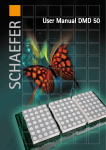
User Manual DMD 16x16
design D 50 Q
design P 50 Q
design P 50 R
Kapitelbezeichnung
Kapitelbezeichnung
X.X Unterpunkt
SCHAEFER GmbH
Winterlinger Str. 4
72488 Sigmaringen
Germany
Phone +49 7571 722-0
Fax +49 7571 722-99
[email protected]
www.ws-schaefer.de
Support
If you have any questions regarding this product please contact:
Phone +49 7571 722-51
Fax +49 7571 722-99
Copyright
Duplication (copy, print, microfilm or any other form) as well
as electronic spreading of this document
is only permitted after formal writting consent of SCHAEFER GmbH.
SCHAEFER GmbH reserves the right to carry out alterations
of technical details without prior notice.
For all transactions our General Conditions of Sale
and Delivery shall be applicable.
All rights reserved.
Ress. 013221
Revision: 2010-04-20
2
Index
User manual DMD 16x16
Index
1
General description ................................ 4
2
Illustration................................................ 4
3
Configuration........................................... 5
4
Contacting................................................ 5
5
5.1
Pin assignment ........................................ 6
Encoder or Connector?............................ 7
6
6.1
6.1.1
6.1.2
6.1.3
6.2
6.2.1
6.2.2
6.2.3
Settings..................................................... 9
Input..................................................................... 10
Control ............................................................... 10
Connection......................................................... 11
Lowest stop........................................................ 11
Dot matrix display........................................... 12
Presentation....................................................... 12
Frequency........................................................... 13
Brightness/Iuminosity..................................... 14
7
Characteristics.......................................... 15
8
Designs...................................................... 15
3
General description | Illustration
1 General description
The DMD 16x16 is a dot matrix display that can be used
as floor and direction indicator. The floor changes can
be displayed stationary, flashing or scrolling. Special
texts can be displayed as ticker (small/big) or defined
as symbols. All functions are adjustable via DIP switches. The characters as well as all functions can be
configured via a PC and edited at any time.
2 Illustration
DMD 16 x16
design
D 50 Q
design
P 50 R
4
design
P 50 Q
Configuration | Contacting
3 Configuration
There are two configuration options:
• The configuration of the DMD 16x16 is
customised by SCHAEFER.
• Do-it-yourself configuration of the DMD 16x16 by means of the DMD Config Kit
(article no. 010575).
4 Contacting
For connecting the DMD 16x16 a Connector or an
Encoder is required.
articel no.
common
anode
common
cathode
Encoder 1 out of 15
006572
006573
Encoder 1 out of 31
005545
005546
Connector
004819
5
Pin assignment
5 Pin assignment
The pin assignment can be modified via the PC (DMD
Config Kit). It must be observed that the assignment
of the Encoder cannot be modified, especially when
pins are defined as special text.
Pin Configuration
V in
GND
Travel
6
Pin
Pin
Pin
Pin
Pin
Pin
Pin
Pin
Pin
Pin
1
2
3
4
5
6
7
8
9
10
Pin assignment
5.1 Encoder or Connector?
5.1 Encoder or Connector?
The chart shows when an Encoder respectively when a
Connector must be used. Depending on the number of
special texts and floors, arrows can be configured and
displayed with/without travelling signal.
Note: When using an Encoder (1 out of
15 or 1 out of 31) the display must be
configured with “Dual” control.
7
Pin assignment
5.1 Encoder or Connector
Special
text or
symbol
none
1
2
3*
4*
8
Floors
Coding (Control)
Display options
Dual/Gray
1 out of n
Arrows
Travelling
up to 5
Connector
Connector
yes
yes
6 up to 15
Connector
Encoder 1 out of 15
yes
yes
16 up to
31
Connector
Encoder 1 out of 31
yes
yes
up to 4
Connector
Connector
yes
yes
5 up to 15
Connector
Encoder 1 out of 15 and Connector
yes
yes
16 up to
31
Connector
Encoder 1 out of 31
yes
no
up to 3
Connector
Connector
yes
yes
4 up to 7
Connector
Encoder 1 out of 15 and Connector
yes
yes
8 up to 15
Connector
Encoder 1 out of 15 and Connector
yes
no
16 up to
31
Connector
Encoder 1 and 31
no
no
up to 2
Connector
Connector
yes
yes
3
Connector
Encoder 1 out of 15 and Connector
yes
yes
4 up to 7
Connector
Encoder 1 out of 15 and Connector
yes
no
8 up to 15
Connector
Encoder 1 out of 15
no
no
16 up to
31
Connector
Encoder 1 out of 15
no
no
up to 2
Connector
Connector
yes
no
3
Connector
Encoder 1 out of 15 and Connector
yes
no
4 up to 7
Connector
Encoder 1 out of 15 and Connector
no
no
8 up to 15
Connector
Encoder 1 out of 15 and Connector
no
no
16 up to
31
Connector
not possible
Settings
6 Settings
Various settings can be done directly on the display by
means of the key respectively the DIP switches. With
the DIP switches the value to be changed is selected,
e. g. brightness; with the respective key various values
can be selected in steps. The setting is saved when the
respective DIP switch is switched off.
OFF
Display function
ON
Input function
LED input
buton
ON
1
2
3
4
DIP switch
9
Settings
7.1 Input | 7.1.1 Control
6.1 Input
By means of the DIP switch 1 the input functions can
be influenced.
6.1.1 Control
By means of the DIP switches 1 and 2 the control
mode can be selected. By means of the key the different control options can be selected in steps. The LEDs
input signalize the current status.
LED: yellow
Dual
button
LED: green
Gray
button
10
button
LED: yellow
1 out of N
Settings
6.1.2 Connection | 6.1.3 Lowest stop
6.1.2 Connection
By means of the DIP switches 1 and 3 the connection
variant can be selected. By means of the key the display can be put on common cathode or common anode. The DIP switches 1 and x are provided for future
functions; they have no effect here.
LED: yellow
button
common
cathode
LED: green
common
anode
button
6.1.3 Lowest stop
By means of the DIP switches 1, 2 and 3 it can be selected which signal shall be valid for the lowest stop.
This signal is either “00000” or “00001” with the control modes Dual and Gray.
LED: yellow
button
LED: green
00001
00000
button
11
Settings
6.2 Dot matrix display | 6.2.1 Presentation
6.2 Dot matrix display
By means of the key the various control modes can be
selected in steps. The dot matrix display will display
the respective settings. The settings are saved when
the respective DIP switch is switched off.
6.2.1 Presentation
By means of the DIP switch 2 the presentation mode
of the character change and of the direction arrows
can be modified.
button
stationary
flashing
If the flashing presentation is selected, the character
change of the floor will be stationary, only the direction arrows will be displayed flashing upon travelling
signal.
12
scrolling
Settings
6.2.2 Frequency
6.2.2 Frequency
By means of the DIP switch 3 the flashing frequency
respectively the scrolling speed can be modified, depending on the mode of character change. With the
stationary presentation mode the DIP switch has no
function.
button
10 c/sec
14 c/sec
18 c/sec
22 c/sec
26 c/sec
2 Hz
4 Hz
6 Hz
8 Hz
10 Hz
13
Settings
6.2.3 Brightness/luminosity
6.2.3 Brightness/luminosity
By means of the DIP switches 2 and 3 the brightness/
luminosity can be modified.
button
80%
85%
90%
DIP switch 4 is provided for future functions; it has
no effect here.
14
95%
100%
Characteristics | Designs
7 Characteristics
Power supply: 12 V … 30 V DC, smoothed
Power consumption:up to 125 mA
Temperature range:0 °C … +65 °C
Luminosity: red 15 mcd/dot
blue 15 med/dot
Control 1 out of n:with additional Encoder up to 31 floors
Control dual/gray: with additional Connector up to 31 floors
8 Designs
The DMD 16x16 is available in square shape,
matching with the Style 50:
D50 DMD 16x16 Q
And in round respectively square shape as
design P 50:
P50 DMD 16x16 R
P50 DMD 16x16 Q
15


