1
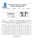
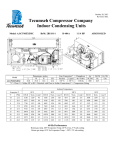
March 16, 2011 Tecumseh Compressor Company Indoor Condensing Units Model: AWG4520EXNXF BoM: 2B3268-1 R-22 1 3/4 HP AIRCOOLED Dimensions, inches Line Connection* Pumpdown Air L W H CH Suction Liquid 90 F 90% SCFM 25.0 33.5 19.5 14.7 7/8” S 3/8” S 19 lbs 1800 AWG4520EXNXF * F = Flare, S = Solder, RF or RS = Rotolock with Flare or Solder Connections, C = Compression Fitting Model Oil Ch Oz. 38.5 Gr. Wt. Lbs. 190 Ambient Temperatures Evaporator T 80F BTUH Watts 90F Cond T BTUH Watts 100F Cond T 110F °F PSIG BTUH Watts Cond T BTUH Watts Cond T 10 32.8 9781 1469 95 8861 1496 15 37.7 11250 1542 97 10236 1576 104 7942 1523 112 7027 1548 121 106 13797 1612 114 8169 1642 123 20 43.0 12752 1617 99 11687 1658 108 10576 1699 116 9412 1739 125 25 48.8 14452 1687 102 13183 1743 110 11968 1793 118 10822 1837 127 30 54.8 16195 1761 104 14890 1824 112 13584 1885 121 12281 1940 129 35 61.5 18042 1836 107 16635 1911 115 15225 1983 123 13828 2048 131 40 68.5 19913 1917 109 18388 2006 117 16959 2085 125 15446 2162 133 45 76.0 21934 1998 112 20296 2101 120 18663 2199 128 17165 2282 135 50 84.0 24131 2076 115 22288 2201 122 20553 2312 130 18824 2416 138 55 92.6 26296 2167 117 24482 2298 125 22670 2423 132 20817 2542 140 60 Hz Performance Return gas temp. 65F, 5F sub cooling March 16, 2011 Specifications/ Parts: Model Unit Bill of Material Nominal Volts-Hz-Ph Refrigeration Range Design Pressure Low Design Pressure High Voltage Range Min. Circuit Ampacity Max. Fuse Size (amps) Compressor Model Comp. Bill of Material Compressor RLA/LRA Overload Relay Run Capacitor Run Capacitor Rating Start Capacitor Start Capacitor Rating Contactor Unit Drawing Wiring Diagram AWG4520EXNXF 2B3268-1 208-230-60-1 20° to 55° 150 450 187 to 254 13.5 20 AWG5520EXN AW703ET-099-P2 9.5 / 52.0 INTERNAL 820ARR3H23 85PR370F20 25MFD 370V(M)VDE 85PS330D17 145-175 MFD 330V VDE 91014 DGU1918-58 91263-02 Fan Motor Fan Motor RLA Fan Blade Fan Guard Fan Shroud High Pressure Switch Low Pressure Control Oil Separator * Condenser Fan Switch Fan Switch Receiver Tank Liquid Valve Liquid Filter * Sight Glass * Suction Valve * Rotolock Valve Gasket Discharge Valve Suction Filter * Accumulator * Crankcase Heater Defrost Timer * Suction Shut Off Valve* Liquid Shut Off Valve* Shrader Valve Body* Valve Core* * = Equipped Units Only Electrical Diagram 810F050C20 (2) 0.7 Each 51568-1 (2) 70831 (2) 70648-2 84095-1 84026-2 704-00002 50855-1 84096-1 84096-2 51082-1 31592 70081 70084 31529-1 30233 56596 70082 TK00042000 91022-1 N/A 56500-K14 56500-K06 56510 56552