1
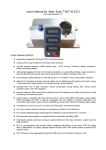
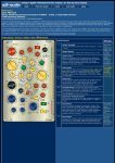
EVB-EMC2101 User Manual
The information contained herein is proprietary to SMSC, and shall be used solely in accordance with the agreement pursuant to which it is provided. Although the information is believed to be accurate, no responsibility is assumed for inaccuracies. SMSC reserves the right to make changes to this document and to specifications and product descriptions at any
time without notice. Neither the provision of this information nor the sale of the described semiconductor devices conveys
any licenses under any patent rights or other intellectual property rights of SMSC or others unless specifically specified
otherwise. The product may contain design defects or errors known as anomalies, including but not necessarily limited to
any which may be identified in this document, which may cause the product to deviate from published specifications.
SMSC products are not designed, intended, authorized or warranted for use in any life support or other application where
product failure could cause or contribute to personal injury or severe property damage. Any and all such uses without prior
written approval of an officer of SMSC will be fully at the risk of the customer. SMSC is a registered trademark of Standard
Microsystems Corporation (“SMSC”).
SMSC DISCLAIMS AND EXCLUDES ANY AND ALL WARRANTIES, INCLUDING WITHOUT LIMITATION ANY AND ALL
IMPLIED WARRANTIES OF MERCHANTABILITY, FITNESS FOR A PARTICULAR PURPOSE, TITLE, AND AGAINST
INFRINGEMENT AND THE LIKE, AND ANY AND ALL WARRANTIES ARISING FROM ANY COURSE OF DEALING OR
USAGE OF TRADE. IN NO EVENT SHALL SMSC BE LIABLE FOR ANY DIRECT, INCIDENTAL, INDIRECT, SPECIAL,
PUNITIVE, OR CONSEQUENTIAL DAMAGES; OR FOR LOST DATA, PROFITS, SAVINGS OR REVENUES OF ANY
KIND; REGARDLESS OF THE FORM OF ACTION, WHETHER BASED ON CONTRACT; TORT; NEGLIGENCE OF
SMSC OR OTHERS; STRICT LIABILITY; BREACH OF WARRANTY; OR OTHERWISE; WHETHER OR NOT ANY REMEDY OF BUYER IS HELD TO HAVE FAILED OF ITS ESSENTIAL PURPOSE, AND WHETHER OR NOT SMSC HAS
BEEN ADVISED OF THE POSSIBILITY OF SUCH DAMAGES.
SMSC EMC2101
1
Revision 1.5 (12-13-06)
EVB-EMC2101 User Manual
1 Overview
The EMC2101 is an environmental monitoring device with a selectable PWM or DAC fan driver output,
one external temperature monitoring channel and one internal temperature monitor. It contains
advanced circuitry to remove errors induced by series resistance and CPU thermal diode process
differences to provide accurate temperature measurements and accurate fan control.
The FAN output can be configured as a PWM (default) or DAC output. The PWM fan driver uses an
eight entry look up table to create a programmable temperature response. The DAC output provides
a linear drive for the system fan circuit using this same look up table.
Finally, the EMC2101-R has two configuration modes and two default fan settings based on the value
of the pull-up-resistor on the ALERT pin. In the Manual Configuration Mode, the device acts as an
SMBus client slave and waits to be configured by the system SMBus master. In the Automatic
Configuration mode, the device automatically queries the SMBus for an EEPROM device and uploads
configuration information from the EEPROM into its internal registers.
All of the modes and functions of the EMC2101 can be tested and observed with the EVB-EMC2101.
The EVB-EMC2101 is a USB-based platform for evaluating both EMC2101 packages (8-MSOP and
8-SOIC).
1.1
Related Documents
The CD included with the evaluation board contains the following documents:
n
Evaluation Board Checklist
n
Bill Of Materials
n
Schematic
n
Jumper Settings and Connector List
n
Datasheet
n
Chip Manager Application
n
Register Definition File (EMC2101.xml)
Revision 1.5 (12-13-06)
2
SMSC EMC2101
EVB-EMC2101 User Manual
2 Getting Started
2.1
System Requirements
To use the EVB you will need:
2.2
2.3
n
A PC running Windows 2000 or XP
n
Display resolution 800x600 (or larger to view several windows simultaneously)
n
An available USB port
Feature Summary
n
Chip Manager (SMSC application) allows viewing and changing register values
n
Graphing of any register
n
Headers for connecting a remote diode or CPU/GPU thermal diode
n
Resistance Error Correction verification
n
Autonomous register loading via included EEPROM (EMC2101-R only)
n
USB communication to evaluation board
n
An external SMBus master may also be used via jumper settings
Installing the EVB
1. Install the Chip Manager (ChipMan) application and device driver on a PC by running Setup.exe
from the ChipMan distribution CD. A revision history and install/uninstall notes may be found in the
readme.txt file on the disk.
2. Connect the supplied USB cable to an available USB port on the PC. Plug the “mini-B” end of the
USB cable into EVB connector P6. The +3.3V and Bridge ACT LEDs should illuminate. After the
EVB is connected to the PC the “Find New Hardware” wizard will pop up for USB driver installation.
Follow the instructions in the readme.txt file to complete the installation process.
3. Start the EVB Software by selecting the Chip Manager application from the SMSC folder from the
Programs Windows Start menu. The EVB will initialize and the Chip Manager Quick Help screen
will appear as in Figure 2.1. The USBAct LED should be blinking when the Chip Manager is
running. For more help with ChipMan, select Help -> Contents for an html based help document
as shown in Figure 2.2.
Note: The SMSC ChipMan application allows viewing and changing register values for a variety of
EVBs including the EMC1001, EMC1002, EMC1023, EMC1033 and EMC2101. The ChipMan
software only needs to be installed once to support all of these EVBs. The list of supported
EVBs may be found in the pulldown menu under Options -> Select Device.
SMSC EMC2101
3
Revision 1.5 (12-13-06)
EVB-EMC2101 User Manual
Figure 2.1 Chip Manager Quick Help Startup Screen
Revision 1.5 (12-13-06)
4
SMSC EMC2101
EVB-EMC2101 User Manual
Figure 2.2 Chip Manager Help Screen
SMSC EMC2101
5
Revision 1.5 (12-13-06)
EVB-EMC2101 User Manual
2.4
Board Layout
The EVB was designed for ease of use and user experimentation with easily accessible jumpers and
access to the SMBus data lines. Figure 2.3 below shows the silk-screen for the EMC2101 EVB.
Figure 2.3 EMC2101 Board Outline and Silk-screen
Revision 1.5 (12-13-06)
6
SMSC EMC2101
EVB-EMC2101 User Manual
3 Hardware Description
3.1
Introduction
The EMC2101 EVB provides the means to demonstrate EMC2101 features and to view and modify
registers. A +12V fan and power supply are provided to demonstrate the fan control functionality. LEDs
indicate status information and test points are included to monitor system voltages with a user provided
voltmeter or oscilloscope. Figure 3.1shows an overview of the EMC2101 EVB.
Figure 3.1 EVB Block Diagram
SMSC EMC2101
7
Revision 1.5 (12-13-06)
EVB-EMC2101 User Manual
3.2
EMC2101
The EMC2101 is an SMBus temperature sensor with 1 internal and 1 external sensor in an 8 pin
MSOP and 8 pin SOIC package. Communications with the EMC2101 sensor is via the SMBus.
3.3
USB to SMBus Bridge
The USB to SMBus bridge is based on an 8051 micro controller with integrated USB and SMBus
interfaces as well as internal flash and RAM. During EVB manufacture, firmware is loaded into the
bridge that provides the interface between the USB and the SMBus. Power is sourced to the micro
controller from the USB interface for device power and communication.
3.3.1
Direct SMBus Connect Option
It is also possible to connect an external SMBus master to the EMC2101 EVB. A few jumper settings
are all that is required to drive the EMC2101:
3.4
n
Simply remove the jumpers on JP6 and connect the SMBus master to the SCL, SDA and ALERT
pins, as well as an external supply for +3.3V.
n
The +3.3V can be supplied by the SMBus bridge by leaving the +3.3V jumper in place and retaining
the USB connection.
Connecting to Remote Diodes
This EVB is populated with jumpers to connect to an external diode or CPU/GPU. If connecting to a
CPU’s thermal diode, it is necessary to provide a common ground. Also, it is usually necessary to bias
the appropriate CPU Vcc plane above this common ground to avoid forward-biasing the ESD diodes
with the temperature sensor signals. Test point TP3, 8, 10, or 11 provides a ground connection. Consult
the CPU manufacturer’s datasheet for guidance on interfacing to the thermal diode. Refer to the
schematic EVB-EMC2101 SCH-7069-REVB1.pdf for details on the EVB header connections.
3.5
Resistance Error Correction (REC)
The remote diode DN signal path has a 100 ohm series resistor to demonstrate the EMC2101’s REC
feature. The resistor may be effectively removed from the circuit by installing a jumper on JP7 or JP13
(-R diode). See Table 3.4 for details on the REC jumper settings.
3.6
Power Source
This EVB requires only a USB cable. The USB-SMBus bridge regulates the +5V USB power to +3.3V
used by the EMC2101 and other EVB ciruitry such as the fan and resistive heater.
3.7
Test Points
Test points are provided for:
n
Ground
n
+3.3V power
n
+5V_USB power
n
FAN pin output
n
ALERT output
n
TACH for 3 wire fan (included)
Revision 1.5 (12-13-06)
8
SMSC EMC2101
EVB-EMC2101 User Manual
3.8
LED Indicators
LEDs indicate the status of the following signals (Table 3.1).
Table 3.1 LED Status Indicators
LED
SIGNAL
OFF
GREEN
RED
LED1
ALERT
+3.3V power OFF
No ALERT
ALERT
LED2
+3.3V
+3.3V power OFF
+3.3V power ON
NA
LED3
Bridge Activity
NO Activity on
USB/SMBus Bridge
Activity on
USB/SMBus Bridge
NA
LED4
USB Activity
NO Activity on USB port
Activity on USB port
NA
LED5
EMC2101
Power
U10 power OFF
U10 power ON
NA
LED6
EMC2101-R
Power
U11 power OFF
U11 power ON
NA
3.9
Jumper Settings
This EVB has many jumper configurations to evaluate all of the features of the EMC2101.
3.9.1
Device Power
To enable one of the 2 devices on the EVB, use jumpers J2 and J3. When a device is selected, the
appropriate LED will light as shown in Table 3.1. Table 3.2 below summarizes the options. Note: only
one device may be active at a time as both devices have the same SMBus address.
Table 3.2 Device Power
3.9.2
JUMPER
NAME
POSITION 1-2
POSITION 2-3
J2
EMC2101 POWER
U10 power ON
U10 power OFF
J3
EMC2101-R POWER
U11 power ON
U11 power OFF
Fan Control
To adjust the fan control circuit one 3-way jumper is used. The two settings are DAC mode and PWM
mode. The default setting is PWM which requires the fan to be connected to FAN CONN. 1 and the
JP8 shorted from pin 1-2.
If the linear DAC mode is desired, several things need configured. First, JP8 must be shorted from pin
2-3 and the fan must be connected to FAN CONN. 2. Then, the device must be configured for linear
operation via the ChipMan software. Consult the datasheet for these settings.Table 3.3.
Table 3.3 Fan Driver Configuration
FAN DRIVER
CONFIGURATION
JP8
FAN CONNECTOR
PWM
Position 1-2
P9
DAC
Position 2-3
P5
SMSC EMC2101
9
Revision 1.5 (12-13-06)
EVB-EMC2101 User Manual
3.9.3
Remote Diode
The remote diode on board the EMC2101 EVB has a heater and an optional in-line series resistance
adjustment. Checking the REC feature of the EMC2101 is accomplished by removing the jumper on
JP7. This adds 100 ohms of series resistance to the DN line of the diode connection. To return to 0
ohm series resistance, replace the jumper on JP7.
To heat the diode, place a jumper on JP10. To return to ambient conditions, remove JP10. These
remote diode options are summarized in Table 3.4 below.
Table 3.4 Remote Diode Settings
JUMPER
NAME
OPEN
SHORT
JP7
REC
Q11 - 100 ohms in
DN line (diode remote -)
Q11 - 0 ohms in
DN line (diode remote -)
JP13
REC
Q12 - 100 ohms in
DN line (diode remote -)
Q12 - 0 ohms in
DN line (diode remote -)
JP10
HEATER
Ambient temp on remote diode
(Q12)
1.0W resistive heater on remote diode (Q12)
This EVB also allows for an off-board diode to be tested (see Table 3.5). This is done by removing
both jumpers on JP8. Then connect Pin 1 to the ‘remote+’ terminal of the remote diode and Pin 3 to
the ‘remote-‘ terminal of the remote diode. Make sure a common ground exists between the remote
diode (GPU, etc.) and the EMC2101 EVB. Also ensure that the remote diode is properly biased
according to the diode manufacture.
Table 3.5 Remote Diode Configurations
CONFIGURATION
JUMPER
On-board diode (Q11)
JP9
Off-board diode (CPU,
GPU, etc.)
JP9
On-board diode (Q12)
JP12
Off-board diode (CPU,
GPU, etc.)
JP12
PIN 1
PIN 2
short / DP
remote + / DP
PIN 4
short / DN
open
short / DP
remote + / DP
PIN 3
remote - / DN
open
short / DN
open
remote - / DN
open
A unique feature of the EMC2101-R device is the ability to start in one of several different
configurations based on the pull up resistor on the ALERT output. The EVB allows the user to quickly
evaluate each of the 4 configurations by adjusting JP11 as shown in Table 3.6. When using the auto
load via EEPROM, ensure that the Autorefresh Registers is not selected until the loading is complete
(less than 1 sec).
Revision 1.5 (12-13-06)
10
SMSC EMC2101
EVB-EMC2101 User Manual
NOTE: Only one jumper is to be installed on JP11 and a minimum of one jumper must be installed
for the device to operate.
Table 3.6 ALERT Pull-up Resistors - SMBus/FAN MODE
3.10
JUMPER
NAME
OPEN
SHORT
JP11
33k
NA
Auto load via EEPROM Initial FAN 0% Duty Cycle
18k
NA
Auto load via EEPROM Initial FAN 100% Duty Cycle
10k
NA
Host load via SMBus initial FAN 0% Duty Cycle
5.6k
NA
Host load via SMBus initial FAN 100% Duty Cycle
Other Sensor Features
Other features such as Ideality Factor Configuration, Conversion Rate, Digital Filtering, Look-up Table
Functionality, and Standby Mode can be controlled with EMC2101 registers. See the datasheet register
description for details.
SMSC EMC2101
11
Revision 1.5 (12-13-06)
EVB-EMC2101 User Manual
4 Software Description
4.1
Chip Manager Overview
The Chip Manager application (ChipMan) initially displays the main Help screen, where detailed
description of the application’s features may be found. The Help screens can be displayed at any time
by selecting Help from the menu bar. ChipMan enables the user to display temperature readings, set
temperature limits and read/write configuration register values.
4.2
Temperature/Register History Graph
To open a Temperature or Register History Graph window, select the register or registers to plot in the
ChipMan application. then select Options -> Plot Register Data from the menu bar. Once the graph
appears, select Control -> Start to begin plotting data. The history plot continuously updates the
register data reported by the EMC2101. Figure 4.1below is a typical Temperature History with the
external diode starting at room temp and then being heated using the HEATER jumper (JP2).
Figure 4.1 EMC2101 Temperature History Graph
Revision 1.5 (12-13-06)
12
SMSC EMC2101