1
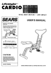
®
0-8MPH
° 2.0HP"STEP
INCLINE°
PROGRAMMABLE
SPEED
Model No. 831.297241
Serial No.
The serial number can be found in the
location shown below. Write the sedal
number in the space above.
Serial Number
_kCAUTION!:
Read all safety precautions and
instructions in this manual
before using this equipment.
Keep this manual in a safe place
for future reference.
OWNER'S MANUAL
SEARS,
ROEBUCK
AND CO., HOFFMAN
ESTATES,
IL 60179
FULL 90 DAY WARRANTY
For 90 days from the date of purchase, when proper assembly and maintenance procedures detailed in
the Owner's Manual are followed, SEARS will, free of charge, repair or replace and install a replacement
part for any defective part, when this treadmill is used in a normal manner.
This warranty does not apply when this treadmill is used for commercial or rental purposes.
SERVICE IS AVAILABLE SIMPLY BY CONTACTING
TER/DEPARTMENT IN THE UNITED STATES.
YOUR NEAREST SEARS SERVICE CEN-
This warranty gives you specific legal dghts, and you may also have other rights which vary from state
to state.
SEARS, ROEBUCK AND CO., DEPT. 817WA,
HOFFMAN ESTATES, IL 60179
2
®
0-8MPH• 2.0HP* STEP
INCLINE
• PROGRAMMABLE
SPEED
TABLE OF CONTENTS
IMPORTANT SAFETY PRECAUTIONS .........................................................
4
BEFORE YOU BEGIN ......................................................................
ASSEMBLY ..............................................................................
5
6
OPERATION AND ADJUSTMENT ............................................................
TROUBLE-SHOOTING AND STORAGE .......................................................
CONDITIONING GUIDELINES ...............................................................
PART LIST ..............................................................................
EXPLODED DRAWING ....................................................................
ORDERING REPLACEMENT PARTS .................................................
_WARNING:
7
10
12
14
15
Back Cover
Before beginning this or any exercise program, consult your physician.
This is especially important for persons over the age of 35 or persons with pre-existing health problems.
Read all Instructions before using. SEARS assumes no responsibility for personal injury or property damage sustained by or through the use of this product.
IMP(:
PRE(
1,
st least 8 feet of clearance behind the treadmill. Do not place the treadmill near water, outdoors o[ on any surface that blocks an air
opening. Do not operate where aerosol products ere used or where oxygen Is being admlnIstercd.
2. When connecting the power cord (sea PLUGGING IN THE POWER CORD on page 7), plug
the power cord directly into a grounded circuit
capable of carrying 12 or more amps. No other
applianCe should be on the same circuit. Keep
the power cord away from heated surfaces. If
an extension cord Is needed, use only a 14gauge general-purpose cord of five feat or less
in length with a three-wire conductor.
3. Never move the walking belt while the power is
turned off. Do not operate the treadmill if the
power cord or plug Is damaged, or If the treadmill is not working properly. (Sea BEFORE
YOU BEGIN on page 5 if the treadmill is not
working properly.)
4. Wear appropriate exercise clothing when
using the treadmill; do not wear loose clothing
that could become caught in the treadmill.
Always wear athletic shoes; never use the
treadmill with bare fea_ wearing only stockIngs or in sandals. Athletic support clothes are
recommended for both men and women.
5. Never start the treadmill while you ere standing on the walking bell Always hold the
handrail when exercising on the treadmill.
4
IS
person on the
treadmill at a time. The treadmill should not be
used by persons weighing more than 250
pounds.
7. Keep small children away from the treadmill at
ell times. Never leave the treadmill unattended
while it is running. Always turn off the power
when the treadmill Is not in use.
8. Never drop or Insert any object Into any opening.
9. To reduce the possibllity of overheating, do
not operate the treadmill continuously for
longer than I hour.
10. The treedmlll is capable of high speeds. Adjust
the speed in small Increments to avoid sudden
jumps In speed.
11. Use the treadmill only as described In this
manual.
12. Always unplug the power cord before performIng the maintenance and adjustment procedures described In this manual. Never remove
the safety cover unlese Instructed to do so by
• an authorized service representative.
Servicing other than the procedures in this
manual should be performed by an authorized
service representative only.
SAVE THESE INSTRUCTIONS
BEFORE .YOUBEGIN_
'_
yOUfor selectlqg _e SEARS.UFESTYLEFP 8.0:::_ _ (excluding.holidays); :To help us assist you/please
EXP _mill_:TheL
FES'r_R8.O'EXP
tm_admiil_!_'_
note the product model number and sedal number
blends advanced technology with innova_tive:designto
before calling. The model number of the treadmill is
let you enjoy an excellent form of cardiovascular exer831.297242. The sedal number can be found on a
cise in the convenience and privacy of your home.
decal attached to the treadmill (see the front cover of
this manual for the location).
For your safety and benefit, read this manual carefully before using the treadmill. If you have addiBefore reading fudher, please review the drawing
tional questions, please call our Customer Service
below and familiarize yourself with the parts that are
labeled.
Department toll-free at 1-800-736-6879, Monday
through Saturday, 7 a.m. until 7 p.m. Central Time
Console
FRONT
Walking Balt_
Foot Rails
Foot Incline Knob_
Power Cord
BACK
Circuit Breaker
On/Off Switch
Rear Roller
Adjustment Bolts
RIGHT S1£
Rear Leg Pad
Note: The rear leg pad may mark some types of linoleum, Mild household cleaning agents will remove any marks.
5
ASSEMBLY
Set the treadmill in a cleared area and remove all packing materials. Do not dispose of the packing materials until
assembly is completed. THE FOLLOWING TOOLS ARE REQUIRED FOR ASSEMBLY: The 7/32" allen
wrench
included and your own adjustable wrench _'_.
.
With the help of a second person, raise the Right Upright (27)
and Left Upright (not shown) to a vertical position. Align the
hole in the lower end of the Right Upright with the hole in the
side of the Frame (50). Insert a 3/8" x 3" Bolt (31), with an
Upright Washer (30), into the Right Upright and tighten the Bolt
into the Frame. Tighten the Bolt that is already in the Right
Upright.
Attach a Bolt and Washer on the left side in the same manner
(not shown).
2. With the help of a second person, rotate the Left and Right
Handrails (1, 11) up as shown. Insert two 3/8" x I 1/4" Bolts
(13) into the Left and Right Uprights (19, 27) and tighten the
Bolts with the 7/32" Allen Wrench (90).
31
2
3. Remove the paper backing from the Wrench Clip (21). Press
the Wrench Clip onto the Frame (50) in the indicated location.
Press the 3/16" Allen Wrench (72) into the Wrench Clip.
50
Make sure that all parts are tightened before using the treadmill.
Note: To protect the floor, a covering should be placed under
the treadmill.
21J_72
6
OPERATION AND ADJUSTMENT
APPLYING SILICONE LUBRICANT
To reduce the friction of the walking belt and minimize wear, a nonoil-, non-petroleum-base silicone lubricant must be applied to the
.walking platform before the treadmill is used. Failure to apply lubricant will reduce treadmill performance. WITH THE POWER CORD
UNPLUGGED, lift each side of the walking beltand spray lubricant
generously onto the indicated area. Reapply lubricant after every
ten hours of use, or whenever performance decreases. Lubricant is
available at most hardware and automotive stores. Uni°Sport TM silicone spray is recommended.
Apply lubricant
to the entire
shaded area.
Silicone
Lubricant
_
PLUGGING IN THE POWER CORD
This product must be grounded. If it should malfunction or break down, grounding provides a path of least
resistance for electric current to reduce the risk of electric shock.
This product is equipped with a cord having an equipment-grounding conductor and a grounding plug. Plug the
power cord Into an appropriate outlet that is properly installed and grounded in accordance with all local
codes and ordinances.
Ak DANG ER:
Improper connection of the equipment-grounding conductor can result in a risk of elec-
tric shock. Check with a qualified electrician or serviceman if you are in doubt as to whether the product is properly grounded. Do not modify the plug provided with the product_f it will not fit the outlet, have a proper outlet
installed by a qualified electrician.
This product is for use on a nominal 120-volt circuit, and has a grounding plug that looks like the plug illustrated in
Drawing 1.
A temporary adapter that looks like the adapter illustrated in Drawing 2 may be used to connect this plug to a 2pole receptacle as shown in Drawing 2 if a properly grounded outlet is not available. The temporary adapter
should be used only until a properly grounded outlet (Drawing 1) can be installed by a qualified electrician. The
green colored rigid ear, lug, or the like extending from the adapter must be connected to a permanent ground
such as a propedy grounded outlet box cover. Whenever the adapter is used it must be held in place by a metal
screw.
Some 2-pole receptacle outlet box covers are not grounded. Contact a qualified electrician to determine if
the outlet box cover is grounded before using an adapter.
Grounded Outlet Box
.2
Outlet Box
Grounding Plug
Grounding
Pin
•Grounding
Grounding Pin
Grounded Outlet
Metal Screw
Plug
7
DIAGRAM OF THE CONSOLE
The heart of the treadmill is the state-of-the-art programmable console. The console offers both manual and program operation, and features an array of independent LCD displays to give you continuousexercise feedback.
Please read these instructions carefully before operating the console. Note: If there is a sheet of protective
plastic on the face of the console, peel it off before operating the console.
AOv, JIrO_ 10 m
_-m#,_.-
_"
_
_
-Z
-Z
-a-,,#,
h_
•l_,mm,_
_
_
[---]
A
(o
_[:Z:_
o
"
o)
rls_
ii/iWt!
_
__.
V
r--nr---n
)
._ED
J
TURNING ON THE POWER
If the safety key is in the console, remove it. Make sure that the on/off switch located
near the power cord is in the ON position (see the drawing at the right). Plug in the
power cord (see PLUGGING iN THE POWER CORD on page 7).
J
Position
ON
Step onto the foot rails of the treadmill. Find the clip attached by a cord to the safety key, and slide the clip onto
the waistband of your clothing.
CAUTION:
Do not stand on the walking belt when turning on the power• Always wear the clip
when using the treadmill; if you fall, the safety key will be pulled from the console, instantly turning off
the power.
Insert the safety key into the console. The four LCD displays will appear. All indicators on the console will light in
sequence. When only the manual indicator is lit, the console will be ready for operetion.
MANUALSPEEDCONTROL
When the power is turned on, the manual indicator will be lit and the console will be in the manual mode. To start
the walking belt, first turn the manual speed control to "reset." Then, turn the control slowly clockwise until the
walking bolt begins to move at slow speed. Note: Each time the walking belt is started, the manual speed
control must first be turned to "reset."
CAUTION:
After the manual speed control is turned, there will be a pause before the walking
belt begins to move. Adjust the speed slowly until you are familiar with the operation of the treadmill.
Hold the handrail and step carefully onto the walking belt. Change the speed of the walking belt as desired by
turning the manual speed control. To stop the walking belt, turn the control to "reset."
PROGRAM SPEED CONTROL
8
When the console is in the program mode, the speed of the walking belt will be controlled automatically by programs you create. To create a program, first press the MODE button repeatedly to select the WALK mode or the
RUN mode. An indicator will light to show which mode you have selected. If the WALK mode is selected, the
speed range of the walking belt will be about 1 to 4 miles per hour during the program; if the RUN mode is selected, the speed range of the walking belt will be about 2 to 8 miles per hour.
Eachprogram is divided into eight equal time periods, called segments. The speed of the walking belt will change
automatically at the beginning of each segment. A speed setting should now be programmed for each of the eight
segments, using the eight programmable speed controls on the left side of the console. The control on the far left
is for the first segment, and the control on the right is for the eighth segment. Move the controls up or down to
program the desired speed settings. If the WALK mode was selected, refer to the scale above the WALK indicator to program speed settings; if the RUN mode was selected, refer to the scale above the RUN indicator. A sample program is shown at the left. This program will begin with a slow speed setting. The speed will then increase
during the second, third and fourth segments, and gradually decrease during the sixth, seventh and eighth segments. An infinite variety of speed settings can be programmed.
Next, press the TIME SET buttons to set the length of time you want the program to last. Each time one of the buttons is pressed, the length of time, shown in the TIME display, will change by 4 minutes. The buttons can be held
down to set the length of time rapidly. The program can be set to last for a minimum of 4 minutes, up to a maximum of 96 minutes.
To start the program, press the START button. The first segment indicator will begin to flash, and after a pause the
walking belt will begin to move at the speed setting.of the first programmable speed control. The TIME display will
show the time remaining in the program. After one-eighth of the length of time you set has elapsed, the second
segment indicator will begin to flash, and the walking belt will change to the speed setting of the second programmable speed control. The program will continue in this manner until the length of time you set has elapsed. The
walking belt will then slow to a stop.
While the program is in progress, the speed of the walking belt can be changed during the current segment, if
desired, by moving the programmable speed control located below the flashing segment indicator.The walking belt
can be stopped while the program is in progress by pressing the MODE button or by removing the safety key from
the console. The console will then be in the same condition as if the program had been completed. After the program is completed, the console can be switched to the manual mode by repeatedly pressingthe MODE button.
CHANGING THE INCLINE
To vary the intensity of your exercise, the inclineof the treadmill can
be changed using the foot incline knob on the right foot rail. Before
changing the incline, stop the walking belt. To increase the
incline, stand with your left foot towards the back of the left foot
rail. Using your right foot, press down the foot incline knob until the
desired incline is reached. To decrease the incline, stand with your
left foot towards the front of the left foot rail, and press down the
foot incline knob until the desired incline is reached.
I
Incline
LCD DISPLAY OPERATION
The four LCD displays provide continuous exercise feedback. The four displays are described below:
CALORIES--This
display shows the approximate number of nutritional Calories that you have burned.
DISTANCE--This
display shows the total distance that you have walked or run, up to 99.9 miles.
SPEED--This display shows the speed of the walking belt.
TIME--When the console is in the manual mode, this display will show the total time that the walking belt has been
moving. (If the treadmill is run for longer than 99 minutes and 59 seconds, the display will reset to zero and the
treadmill will slow to a stop.) If desired, a time goal can be set. To set a time goal, you must first stop the walking
belt. Next, press the TIME SET increase or decrease button. Each time one of the buttons is pressed, the time
goal will change by 1 minute. The buttons can be held down to set a time goal rapidly. While the walking belt is
moving, the display will count down the time goal. When no time remains, the walking belt will slow to a stop. When
the console is in the WALK mode or the RUN mode, the TIME display will show the time remaining in the program.
Note: The CALORIES, DISTANCE and TIME displays can be reset by removing and re-inserting the safety key.
TURNING OFF THE POWER
To tum off the power, remove the safety key from the console. Store the safety key in a secure location.
9
TROUBLE-SHOOTING
AND STORAGE
Most treadmill problems can be solved by following the simple steps below. Find the symptom that applies,
and follow the steps listed. If further assistance is needed, call our Customer Service Department toll-free at 1800-999-3756, Monday through Friday, 6 a.m. until 6 p.m. Mountain Time.
1. SYMPTOM:
THE POWER DOES NOT TURN ON
a. Make sure that the power cord is plugged into a properly grounded outlet. (See PLUGGING IN THE
POWER CORD on page 7.) If an extension cord is needed, use only a 14-gauge general-purpose cord of
five feet or less in length.
b. After the power cord has been plugged in, make sure that the safety key is fully inserted into the console.
Various indicators on the console should light. (See OPERATION AND ADJUSTMENT on page 7.)
c. Check the circuit breaker located on the treadmill near the
power cord. If the switch protrudes as shown, the circuit breaker has tripped. To reset the circuit breaker, wait for five minutes and then press the switch back in.
Tripped
d. Check the on/off switch located on the treadmill near the
power cord. The switch must be in the ON position.
2. SYMPTOM:
_
Reset
°"¢¢
THE POWER TURNS OFF DURING USE
a. Check the circuit breaker located on the treadmill near the power cord. If the circuit breaker has tripped (see
the drawing above.), wait for five minutes and then press the switch back in.
b. Make sure that the power cord is plugged in.
c. Remove the safety key from the console. Reinsert the safety key fully into the console. Various indicators on
the console should light.
d. Check to make sure the on/oft switch is in the ON position. (See 1. d. above.)
e. If the treadmill stillwill not run, please call our Customer Service Department.
3. SYMPTOM:
THE WALKING BELT SLOWS WHEN WALKED ON
a. Apply silicone lubricant to the walking platform before use. Reapply lubricant after every 10 hours of use,
and whenever a decrease in performance is noticed. (Uni.Sport silicone spray is recommended.) CAUTION: UNPLUG THE POWER CORD WHEN APPLYING LUBRICANT. (See OPERATION AND ADJUSTMENT on page 7 for application instructions.)
b. If an extensioncord is needed, use onlya 14-gauge generel-purpose cord of five feet or less in length.
C.
10
If the walking belt is overtightened, treadmill performance may
decrease and the walking belt may be permanently damaged.
Remove the safety key and UNPLUG THE POWER CORD.
Using the 3/16" allen wrench, turn both rear roller adjustment
bolts counterclockwise, 1/4 of a turn. When the walking belt is
properly tightened, you should be able to lift each side of the
walking belt 3-4 inches off the walking platform. The center of
the walking belt should just touch the walking platform. Be careful to keep the walking belt centered. Plug in the power cord,
insert the safety key and run the treadmill for a few minutes.
Repeat until the walking belt is properly tightened.
I R_justment
Bolts
4. SYMPTOM:
THE WALKING
BELT IS OFF-CENTER
OR SLIPS WHEN WALKED ON
a. If the walking belt has shifted to the left, first remove the safety
key and UNPLUG THE POWER CORD. Using the 3/16" allen
wrench, turn the left rear roller adjustment bolt clockwise, and
the right bolt counterclockwise, 1/4 of a turn each. Be careful not
to overtighten the walking belt. Plug in the power cord, insert the
safety key and run the treadmill for a few minutes. Repeat until
the walking belt is centered.
a
ir
b. If the walking belt has shifted to the right, first remove the safety
key and UNPLUG THE POWER CORD. Using the 3/16" allen
wrench, turn the left rear roller adjustment bolt counterclockwise,
and the right bolt clockwise, 1/4 of a turn each. Be careful not to
overtighten the walking belt. Plug in the power cord, insert the
safety key and run the treadmill for a few minutes. Repeat until
the walking belt is centered.
c. If the walking belt slips when walked on, first remove the safety
key and UNPLUG THE POWER CORD. Using the 3/16" allen
wrench, turn both rear roller adjustment bolts clockwise, 1/4 of a
tum. When the walking belt is correctly tightened, you should be
able to lift each side of the walking belt 3-4 inches off the walking
platform. The center of the walking belt should just touch the
walking platform. Be careful to keep the walking belt centered. Plug
in the power cord, insert the safety key and run the treadmill for a
few minutes. Repeat until the walking belt is properly tightened.
STORAGE
Unplug the power cord when the treadmill is not in use. Remove the
indicated bolt and washer from the lower end of each upright. Loosen
the other bolts in each upright. Carefully rotate the uprights down. It is
recommended that the treadmill be covered during extended periods
of storage.
11
CONDITIONING GUIDELINES
Th e following guldellnes Willhelp you to plan y0ur. _ i, :: :_:During the.fi_t fe._._onths of y0_e:<e_c_'se-pr_gram,
exemlse program. Remember that proper nutdtion and _ : keep your head.iate.llear the Io_/end_f _,ourrtraining
adequate rest are essential for successful results.
zone as you exemlse.' After a few months, _;ou'rheart
rate can be increased gradually until it is near the midbeginning this or
dle of your training zone as you exercise.
WARNING: Bofore
any exerctse program, consult your physlclan. This
Is especlally Important for Individuals over the age
of 36 or Individuals wlth pre-exlsting health prob.
lems.
EXERCISE INTENSITY
To maximize the benefits of exercising, it is important
to exercise with the proper Intensity. The proper intensit,/can be found by using your heart rate as a guide.
For effective aerobic exercise, your heart rate should
be maintained at a level between 70% and 85% of
your maximum head rate as you exercise. This is
known as your training zone. You can find your training
zone in the table below. Training zones are listed for
both unconditioned and conditioned persons according
to age.
12
AGE
UNCONDITIONED
TRAINING ZONE
(BEATS/MIN
CONDITIONED
TRAINING ZONE
(BEATS/MIN
20
138-167
133"162
25
136-165
132-160
30
135-164
130-158
35
134-162
129-156
40
132-161
127-155
45
131-159
125-153
50
129-156
124,'150
55
127-155
122-149
60
126.153
121-147
65
125-151
119-145
70
125-150
118-144
75
122-147
117-142
8g
120-146
116.140
55
118-144
114-139
To measure
your bead rate,
stop exercising
and place two
fingers on your
wdst as
shown. Take a
six-seccnd
heartbeat
count, and
multiply the
result by 10 to
find your heart rate. For example, if your six-second
beartbeat count is 14, your head rate is 140 beats per
minute. (A six-second count is used because your
heart rate will drop rapidly when you stop exercising.)
Adjust the intensity of your exercise until your heart
rate is at the proper level.
WORKOUT GUIDEUNES
Each workout should consist of three basic pads: a
warm-up, 20 to 30 minutes of training zone exercise,
and a cool-down. Warming up prepares the body for
exercise by increasing circulation, delivering more oxygen to the muscles and raising the body temperature.
Begin each workout with 5 to 10 minutes of stretching
and light exercise to warm up. Then, increase the
intensity of your exercise to raise your heart rate'to
your training zone for 20 to 30 minutes. Breathe regularly and deeply as you exercise--never hold your
breath. Finish each workout with 5 to 10 minutes of
stret_ing to cool down. This will increase the flexibility
of th_'musclas, and reduce soreness and other postexercise problems.
To maintain or improve your condition, complete three
workouts each week, with at least one day of rest
between workouts. After a few months of regular exercise, you may complete up to five workouts each week,
if desired. The key to success is CONSISTENCY.
SUGGESTED
STRETCHES
•The following stretches can provide a gond warm-up or cooFdown, Correct form for each_stretch is sh-(_vn in the
drawings below. Move slowly as you stretch_never'b0unce.
TOE TOUC H STRETCH
-
Stand with your knees bent slightly and slowly bend forward
from your hips. Allow your back and shoulders to relax as you
reach down toward your toes as faras possible. Hold for 15
•counts, then relax. Repeat 3 times.
Stretches: Hamstrings, back of knees and back.
HAMSTRING
STRETCH
Sit with one leg extended. Bdng the sole of the opposite foot
toward you and rest it against the Inner thigh of your extended
leg. Reach toward your toes as far as possible. Hold for 15
counts, then relax. Repeat 3 times for both legs.
Stretches: Hamstrings, lower back and groin.
CALF/ACHILLES STRETCH
With one leg in front of the other, reach forward and place your
hands against a walLKeep your back leg straight and your
back foot flat on the floor. Bend your front leg, lean forward and
move your hips toward the wall. Hold for 15 counts, then relax.
Repeat 3 times for both legs. To cause further stretching of the
achilles tendons, bend your back leg as well.
Stretches: Calves, achilles tendons and ankles.
QUADRICEPS STRETCH
With one hand against a wall for balance, reach back and grasp
one foot with your other hand. Bring your heel as close to your
buttocks as possible. Hold for 15 counts, then relax. Repeat 3
times for both legs.
Stretches: Quadriceps and hip muscles.
INNER THIGH STRETCH
Sit with the soles of your feet together and your knees outward.
Pull your feet toward your groin area as far as possible. Hold
for 15 counts, then relax. Repeat 3 times.
Stretches: Quadriceps and hip muscles.
PART LIST--Model
14
Key
No.
Part
No.
1
2
3
4
5
6
7
8
9
10
11
12
13
14
15
16
17
18
19
20
21
22
23
24
25
26
27
28
29
30
31
32
33
34
35
36
37
38
39
40
41
42
43
44
45
46
47
48
49
50
51
52
53
54
55
120786
116926
111869
120718
120803
120065
114001
013141
113203
119038
120787
013438
119994
114005
119429
100994
120066
118017
120293
120445
016028
120800
119428
109365
118153
120168
120292
112609
110447
014132
112001
113204
013162
118148
108080
105989
120642
019084
109382
119163
031229
117806
052014
119026
012056
119416
118650
120716
119502
NSP
112669
118569
116768
122002
114270
Qty.
1
2
8
1
1
1
1
4
2
1
1
2
2
2
1
2
1
1
1
1
2
1
1
1
1
1
1
1
1
4
4
2
17
1
11
1
1
1
1
1
1
2
2
1
2
1
1
1
4
1
2
1
1
1
2
No. 831.297241
Description
Left Handrail
Cable "rie
Cage Nut
Console
Speed Control Knob
Long Wire Harness
Console Plate
Console Screw
6" Cable Loom
Safety Key/Clip
Right Handrail
Console Bolt
3/8" x I 1/4" Bolt
Handrail Cap
Front Left Endcap
Motor Bolt
Short Wire Harness
Belt
Left Upright
Front Roller Pulley
Wrench Clip
Right Foot Rail
Front Right Endcap
Choke
Reed Switch/Sensor Wire
Extension Wire
Right Upright
Front Roller Adj. Bolt
Controller
Upright Washer
3/8" x 3" Bolt
12" Cable Loom
Safety Cover Screw
BeltGuide
Screw
Controller Wire
Electronics Bracket
Grommet
Circuit Breaker
On/Off Switch
Power Cord
Wheel Bolt
Front Wheel
Power Cord Bracket
Wheel Nut
Safety Cover Bracket
Incline Leg
Power Board
Plastic Spacer
Frame
Shock Pin
Shock Bracket
Shock Cushion
Incline Shock
Shock Spacer
R1094A
Key
No.
Part
No.
Qty.
56
57
58
59
60
61
62
63
64
65
66
67
68
:69
70
71
72
73
74
75
76
77
78
79
80
81
82
83
84
85
86
87
88
89
90
91
92
93
94
95
96
97
98
#
#
#
#
#
#
#
#
#
#
#
106334
012149
120909
013547
118202
119919
110407
013028
119431
120867
122282
116435
116434
016029
016057
105444
045010
014127
113278
109788
119430
119779
120710
120711
119935
120801
120802
120799
120780
120713
120785
107503
105477
013510
045017
116927
013540
014086
120866
104188
054023
120630
122137
102634
107771
118201
102246
101898
112083
109407
101897
114011
118204
122139
2
3
1
3
1
1
1
4
1
2
1
1
1
4
4
2
1
3
1
1
1
8
1
1
1
1
1
1
2
1
1
1
2
4
1
3
3
5
7
2
2
2
2
1
1
1
1
1
1
1
1
1
1
1
Description
Cotter Pin
Leg Nut/Motor Pivot Nut
Choke Bracket
Leg Bolt/Motor Tension Bolt
Shock Release
Incline Cable
Rear Leg Pad
Rear Endcap Screw
Right Rear Endcap
Lock Nut
Incline Knob Bracket
Incline Lever
Foot Incline Knob
4" Cable Tie
8" Cable Tie
Rear Roller Adj. Bolt
3116"Allen Wrench
Roller Adj. Washer
Pulley/Flywheel/Fan
Rear Roller
Left Rear Endcap
Platform Screw
Walking Platform
Walking Belt
Incline Knob Sleeve
Front Safety Cover
Rear Safety Cover
Left Foot Rail
Deck Shim
Motor
Motor Mounting Bracket
Motor Swivel Bolt
Motor Nut
Power Board Screw
7/32" Allen Wrench
Tie Holder
Tie Holder Screw
3/8" Flat Washer
Small Screw
Flat Washer
Wire Clip
Choke Screw
Handrail Bolt
Ground Wire
Power Cord-Power Board Wire
Red Motor-Controller Wire
White Power Board-Frame Wire
Breaker-Power Board Wire
Blue Controller-Motor Wire
Oh/Off Switch-Breaker Wire
14" White Wire, 2 Female
4" Black Wire, Male-Female
8" Blue Wire, Male-Female
Owner's Manual
Note: "#" indicates a non-illustrated part. Specifications are subject to change without notice. See the back cover
for information about ordering replacement parts.
EXPLODED DRAWING---Model No. 831.297241
R1094A
3
8
14
3
8
98
18
11_
16
98
13
85
9O
15
30 _
93
20
'i
28
59
,93
82
76
30
81
79
/
"17
34
80
31
6
1_7 35
,-39
.40
56 =
41
59
15
ORDERING REPLACEMENT
PARTS
Each TREADMILL has its own MODEL NUMBER. Always mention this MODEL NUMBER when requesting service or repair parts for your TREADMILL.
All parts listed herein can be ordered through SEARS, ROEBUCK AND CO. SERVICE CENTERS and most
SEARS RETAIL STORES. If parts you need are not stocked locally, your order will be transmitted to a SEARS
PARTS DISTRIBUTION CENTER for handling.
WHEN ORDERING REPAIR PARTS, ALWAYS GIVE THE FOLLOWING INFORMATION:
1. The MODEL NUMBER of the product (831.297241).
2. The NAME of the product (SEARS LIFESTYLER ° 8.0 EXP).
3. The PART NUMBER of the part(s) from page 14 of this owner's manual.
4. The DESCRIPTION
of the part(s) from page 14 of this owner's manual.
Your SEARS TREADMILL has added value when you consider that SEARS has service units nationwide, staffed
with SEARS trained technicians specifically trained on SEARS products, having the parts, tools and equipment to
ensure that we meet our pledge to you: "We service what we sell."
Should you ever need repair service or parts, call toll free:
For repair service: 1-800-4-REPAIR
For repair parts: 1-800-FON-PART
(1-800-473-7247)
(1-800-366-7278)
Part No. 122139 R1094A Printed in USA
© 1994 Sears, Roebuck and Co.