1
CERTANCE
Online User's Guide
DAT 7 2 / D D S - 4 6 - S l o t Au t o l o a d e r
i
Copyright and Trademarks
Copyright © 2003 by Certance LLC. All Rights Reserved.
Part Number 50000999
August, 2003
Certance and the Certance logo are trademarks of Certance LLC. Seagate is a trademark of Seagate
Technology LLC. Other product names are trademarks or registered trademarks of their respective owners.
Certance reserves the right to change, without notice, product offerings or specifications. No part of this
publication may be reproduced in any form without written permission from Certance LLC.
Certance provides this manual “as is,” without warranty of any kind, either expressed or implied, including, but
not limited to, the implied warranties of merchantability and fitness for a particular purpose. Certance reserves
the right to change, without notification, the specifications contained in this manual.
Certance assumes no responsibility for the accuracy, completeness, sufficiency, or usefulness of this manual, nor
for any problem that might arise from the use of the information in this manual.
Warnings
All safety and operating instructions should be read before this product is operated, and should be retained for
future reference. This unit has been engineered and manufactured to assure your personal safety. Improper use
can result in potential electrical shock or fire hazards. In order not to defeat the safeguards, observe the
following basic rules for installation, use and servicing.
CAUTION: This symbol should alert the user to the presence of “dangerous voltage” inside the
product that might cause harm or electric shock.
Caution! Risk of electric shock! Do not open!
To reduce the risk of electric shock, do not remove the cover (or back). No user-serviceable parts
are inside. Refer servicing to qualified service personnel.
•
Heed warnings — All warnings on the product and in the operating instructions should be adhered to.
•
Follow instructions — All operating and use instructions should be followed.
•
Ventilation — The product should be situated so that its location or position does not interfere with proper
ventilation.
•
Heat — The product should be situated away from heat sources such as radiators, heat registers,
furnaces, or other heat producing appliances.
•
Power sources — The product should be connected to a power source only of the type directed in this
document or as marked on the product.
•
Power cord protection — The power cord should be routed so that it is not likely to be walked on or
pinched by items placed upon or against it, paying particular attention to the cord at the wall receptacle,
and the point where the cord exits from the product.
•
To complete the disconnection of the electricity, please remove the power (electric) cord and the SCSI
cable from their connections in the back of the product. The plugs should be placed near the product for
easy access.
•
Object and liquid entry — Care should be taken to insure that objects do not fall and liquids are not
spilled into the product's enclosure through openings.
•
Servicing — The user should not attempt to service the product beyond that described in the operating
instructions. All other servicing should be referred to qualified service personnel.
Precautions
•
Do not use oil, solvents, gasoline, paint thinners, or insecticides on the unit.
•
Do not expose the unit to moisture or to temperatures higher than 104 °F (40 °C) or lower than -40 °F (40°C).
•
Keep the unit away from direct sunlight, strong magnetic fields, excessive dust, humidity, and electronic/
electrical equipment, which generate electrical noise.
•
Hold the power cord by the head when removing it from the AC outlet; pulling the cord can damage the
internal wires.
•
Use the unit on a firm level surface free from vibration, and do not place anything on top of the unit.
FCC Notice
This equipment generates and uses radio frequency energy and, if not installed and used properly — that is, in
strict accordance with the manufacturer's instructions — may cause interference to radio communications or
radio and television reception. It has been tested and found to comply with the limits for a Class B computing
device in accordance with the specifications in Part 15 of FCC Rules, which are designed to provide
reasonable protection against such interference in a residential installation. However, there is no guarantee that
interference will not occur in a particular installation. If this equipment does cause interference to radio or
television reception, which can be determined by turning the equipment on and off, you are encouraged to try
to correct the interference by one or more of the following measures:
•
Reorient the receiving antenna.
•
Relocate the computer with respect to the receiver.
•
Move the computer into a different outlet so that the computer and receiver are on different branch
circuits.
If necessary, you should consult the dealer or an experienced radio/television technician for additional
suggestions. You may find the booklet, How to Identify and Resolve Radio-TV Interference Problems, prepared
by the Federal Communications Commission, helpful. This booklet (Stock No. 004-000-00345-4) is available
from the U.S. Government Printing Office, Washington, DC 20402.
WARNING: Changes or modifications made to this equipment, which have not been expressly
approved by Certance, may cause radio and television interference problems that could void
the user's authority to operate the equipment.
Further, this equipment complies with the limits for a Class B digital apparatus in accordance with Canadian
Radio Interference Regulations.
The desktop device drive described in this manual requires shielded interface cables to comply with FCC
emission limits.
WARNING: To prevent fire or electrical shock hazard, do not expose the unit to rain or
moisture.
To avoid electrical shock, do not open the cabinet.
Refer servicing to qualified personnel.
Contents
List of Figures ..................................................................... 8
List of Tables........................................................................ 9
Chapter 1 - Introduction ................................................... 10
Features ............................................................................. 10
Capacity and Transfer Rates ................................................... 11
Applications ........................................................................ 11
Using This Guide .................................................................. 12
Chapter 2 - Quick Start Installation ................................ 13
Before you begin .................................................................. 13
Autoloader Components ........................................................ 14
Installing a Desktop Autoloader ............................................... 14
Installing an Internal Autoloader .............................................. 15
Chapter 3 - Installing the Autoloaders .......................... 16
Unpacking and Inspection ...................................................... 16
Installing the Desktop Autoloader ............................................. 16
Installing the Internal Autoloader .............................................. 20
Chapter 4 - Operating Your Autoloader ........................ 28
Using the Appropriate Media .................................................. 28
Starting the Autoloader .......................................................... 29
Handling Cartridges ............................................................. 29
Applying Labels ................................................................... 30
Loading a Cartridge ............................................................. 30
Ejecting a Cartridge or Magazine ............................................ 31
Write-Protecting a DAT Cartridge and Magazine ......................... 33
Cleaning the Tape Path .......................................................... 34
Preparation for Shipping ........................................................ 35
Chapter 5 - Understanding the Drive LEDs .................... 37
Front Panel LEDs ................................................................... 37
LED Summary ...................................................................... 38
Clean LED ........................................................................... 39
6
Media LED .......................................................................... 39
Drive LED ............................................................................ 40
About the Operator Panel LCD Display ...................................... 41
Chapter 6 - Configuration for Novell and UNIX ........... 44
Operating System Configuration .............................................. 44
Chapter 7 - Troubleshooting ........................................... 53
Missing or Damaged Parts ..................................................... 53
SCSI ID Problems ................................................................. 53
SCSI Termination Problems ..................................................... 54
Drive Does Not Work ............................................................ 54
Power On Self Test Fails ......................................................... 54
Computer Does Not Boot ....................................................... 54
Computer Does Not Recognize Drive ........................................ 54
Backup Program Does Not Recognize Drive ............................... 55
Write Error .......................................................................... 55
Hardware Error .................................................................... 55
Appendix A - Loading Revised Firmware ...................... 56
Firmware Upgrade Methods ................................................... 56
Using Firmware Cartridges ..................................................... 56
7
List of Figures
Figure
Figure
Figure
Figure
Figure
Figure
Figure
Figure
Figure
Figure
Figure
Figure
Figure
Figure
Figure
1. Front Panel Components ......................................................................... 14
2. Autoloader Rear Panel............................................................................ 18
3. SCSI Termination Examples ..................................................................... 19
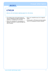
4. Jumper Pins on the Back of the Internal Autoloader..................................... 21
5. DIP-Switch Settings for the Internal Autoloader ........................................... 23
6. Locations of Mounting Holes.................................................................... 25
7. Interface Connectors on the Internal Autoloader......................................... 26
8. Two SCSI Termination Examples for the Internal Autoloader ........................ 26
9. Loading a Cartridge into the Autoloader Magazine ................................... 30
10. Loading a Magazine into the Autoloader................................................ 31
11. Write-protecting a DAT Cartridge .......................................................... 33
12. Write-protect switch on autoloader magazine.......................................... 33
13. Front Panel LEDs .................................................................................. 37
14. LCD display features............................................................................. 41
15. Operating System DIP Switches ............................................................. 45
8
List of Tables
Table
Table
Table
Table
Table
Table
Table
Table
Table
Table
1. DDS-4 and DAT 72 Autoloader Capacity and Transfer Rates........................ 11
2. Default Configuration (Desktop Drive) ........................................................ 17
3. Default Configuration (Internal Drive)......................................................... 20
4. Matching Drives with the Media They Support ............................................ 28
5. Cartridge Guidelines and Pitfalls............................................................... 29
6. Cleaning the Autoloader.......................................................................... 34
7. LED Quick Summary................................................................................ 38
8. Clean LED .............................................................................................. 39
9. Media LED ............................................................................................. 39
10. Drive LED ............................................................................................. 40
9
1. Introduction
The Certance DAT 72 and DDS-4 tape autoloaders are fully integrated, intelligent, multi-cartridge
tape systems that support the (Digital Data Storage) DDS-2 (DDS-4 autoloader only), DDS-3, DDS-4,
and DAT 72 (DAT 72 autoloader only) 4mm tape formats. They include a magazine that can
accommodate up to six (6) data cartridges.
These autoloaders are an internal or standalone desktop subsystem that connects to a host system
using an LVD 2 68-pin shielded SCSI cable.
The autoloader combines established DDS technology, high-density recording and hardware data
compression capability to provide unmatched reliability and performance.
NOTE: These autoloaders will not work in a SCSI-1 environment.
Features
The following list summarizes the key features of the DDS-4 and DAT 72 autoloader drives.
•
Compatibility
•
DDS-4: Supports DDS-2, DDS-3, and DDS-4 recording formats.
•
DAT 72: Supports DDS-3, DDS-4, and DAT 72 recording formats.
•
Support for various native data-storage capacities
•
High-speed transfer rates for fast backups
•
Advanced onboard DDS-DC hardware using Lempel-Ziv (DCLZ) data-compression, doubling
the drive’s uncompressed capacity (e.g., a 20 GB uncompressed drive can be 40 GB with
compression)
•
High-performance SCSI burst transfer rates
•
Three levels of error-correction code (ECC) and four-head design for read-after-write (RAW)
error detection and correction (uncorrectable error rate of less than 1 in 1015 bits)
•
“Flying” preamplifier for greater signal-to-noise ratio
•
Flash memory to store setup parameters and enable field firmware upgrades
•
Automatic Power On Self Test
•
State-of-the-art sealed drive mechanism and tape handling components for improved immunity
to airborne contaminants and extended media life.
10
Introduction
Capacity and Transfer Rates
Capacity and Transfer Rates
The Certance DAT 72 and DDS-4 autoloaders provide the following capacities and sustained data
transfer rates, depending upon the type and length of tape media used. These capacities and
transfer rates are based on an assumed 2:1 data compression rate. Uncompressed (native)
capacities are one-half these values.
Table 1. DDS-4 and DAT 72 Autoloader Capacity and Transfer Rates
Tape format
DDS-2*
DDS-3
DDS-4
DAT-72
120
125
150
170
8
24
40
72
Six-Cartridge Magazine Capacity (Gbytes)
48
144
240
432
Sustained Data Transfer Rate
(Mbytes/sec)
2.2
5.5
5.5
7.0
Tape Length (meters)
Single-Cartridge Capacity
(Gbytes)
* Applies to DDS-4 drives only
NOTE: 60-meter DDS data cartridges cannot be used with these autoloaders. The use of 90meter DDS data cartridges is not recommended for these products. The DAT 432 autoloader will
reject 90-meter tapes if they are inserted.
Applications
The Certance DAT 72 and DDS-4 autoloaders are ideal for server and network/enterprise
applications, including:
•
Backup of high-capacity hard drives or disk arrays
•
Automated storage management
•
On-line, unattended data collection
•
Near-line secondary storage for text, graphics or multimedia data of all types
•
Archival storage.
11
Introduction
Using This Guide
Using This Guide
This User’s Guide describes how to install, configure, and care for the DDS-4 and DAT 72
autoloader tape drives. Please read the appropriate chapters and appendixes carefully, and keep
this Guide handy for future reference.
•
Chapter 2 provides quick-start instructions for getting the drives up and running in the
shortest possible time.
•
Chapter 3 describes how to install the DDS-4 and DAT 72 autoloader drives.
•
Chapter 4 describes how to operate the drives.
•
Chapter 5 describes the autoloader LEDs.
•
Chapter 6 describes the configuration for Novell and UNIX operating systems.
•
Chapter 7 provides troubleshooting procedures you can follow in the unlikely event you
encounter a problem with your drive.
•
Appendix A describes how to upgrade firmware for your tape drive.
12
2. Quick Start Installation
This chapter provides quick-start instructions for getting the autoloader tape drives up and running in
the shortest possible time.
Topics in this chapter are:
•
“Before you begin” on page 13
•
“Autoloader Components” on page 14
•
“Installing a Desktop Autoloader” on page 14
•
“Installing an Internal Autoloader” on page 15
NOTE: If you prefer more detailed instructions, see Chapter 3 for drive installation
instructions.
Before you begin
Precautions
CAUTION: Observe the following precautions to avoid electrostatic damage to the internal
autoloader.
•
Do not remove the drive from the antistatic bag until you are ready to install it.
•
Before you remove the drive from the antistatic bag, touch a grounded metal surface to
discharge any static electricity buildup from your body.
•
Hold the drive only by its edges and avoid direct contact with any electronic components.
•
If you need to put down the drive, lay it on top of the antistatic bag or place it inside the bag.
13
Quick Start Installation
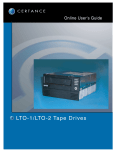
Autoloader Components
Autoloader Components
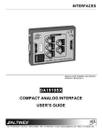
The following describes the major components of the autoloader.
EJECT
EJECT
button
button
SELECT
SELECT
button
button
ENTER
ENTER
button
button
Clean
Clean
LED
LED
(green)
(green)
Media
Media
LED
LED
(green)
(green)
Drive
LED
Drive LED
(amber)
(amber)
LCD
LCD
Display
Display
Figure 1. Front Panel Components
For more information on LEDs and their meaning, see “Front Panel LEDs” on page 37.
Installing a Desktop Autoloader
Use the following procedure to install a desktop autoloader. Print this page and check each step as
you complete it. If you need more information about a step, turn to the section referenced in the step.
❑
1.
Unpack the contents of your drive package, and check for missing or damaged items.
See “Unpacking and Inspection” on page 16.
❑
2.
Review the drive’s default settings and change them if necessary:
•
•
•
•
•
•
•
•
•
SCSI ID: 6
Parity Checking: Enabled
Terminator Power: Disabled
Data Compression: Enabled
Media Recognition (DDS-4 drives only): Enabled
Power On Self Test (POST): Enabled
Host Operating System: Windows 98 SE/ME/XP/NT/2000/Windows Server 2003
SCSI Interface Compatibility: Ultra 2 Wide SCSI for DDS-4 and DAT 72 autoloader
Vendor ID: SEAGATE DAT
See“Configuring the Desktop Autoloader” on page 17.
❑
3.
Connect a SCSI interface cable to the drive.
See “Connecting the SCSI Interface Cable” on page 18.
❑
4.
Be sure the tape drive is not the last device on the SCSI bus (the drive does not provide
SCSI termination).
See “Installing SCSI Termination” on page 19.
❑
5.
Connect a power cable to the drive.
See “Connecting the Power Cord” on page 19.
14
Quick Start Installation
Installing an Internal Autoloader
Installing an Internal Autoloader
Use the following procedure to install an internal autoloader. Print this page and check each step as
you complete it. If you need more information about a step, turn to the section referenced in the step.
❑
1.
Unpack the contents of your drive package, and check for missing or damaged items.
See “Unpacking and Inspection” on page 16.
❑
2.
Review the drive’s default settings and change them if necessary:
•
•
•
•
•
•
•
•
•
SCSI ID: 6
Parity Checking: Enabled
Terminator Power: Disabled
Data Compression: Enabled
Media Recognition: Enabled
Power On Self Test (POST): Enabled
Host Operating System: Windows 98 SE/ME/XP/NT/2000/Windows Server 2003
SCSI Interface Compatibility: Ultra 2 Wide SCSI for DDS-4 and DAT 72 autoloader
Vendor ID: SEAGATE DAT
See“Configuring the Internal Autoloader” on page 20.
❑
3.
Mount the drive horizontally in a 5.25-inch, full-height drive bay.
See “Mounting the Internal Autoloader” on page 24.
❑
4.
Connect a SCSI interface cable to the drive.
See “Connecting the SCSI Interface Cable” on page 25.
❑
5.
Be sure the tape drive is not the last device on the SCSI bus (the drive does not provide
SCSI termination).
See “Installing SCSI Termination” on page 26.
❑
6.
Connect a power cable to the drive.
See “Connecting the Power Cord” on page 27.
15
3. Installing the Autoloaders
This chapter describes how to install the desktop and internal DDS-4 and DAT 72 autoloaders.
Topics in this chapter are:
•
“Unpacking and Inspection” on page 16
•
“Installing the Desktop Autoloader” on page 16
•
“Installing the Internal Autoloader” on page 20
Unpacking and Inspection
Although Certance autoloaders are inspected and carefully packaged at the factory, damage may
occur during shipping. Follow these steps for unpacking the autoloader.
1.
Before you unpack the contents of your autoloader package, inspect the shipping containers
for damage. If you spot damage to the container, notify your shipper immediately.
2.
Place the shipping container on a flat, clean, stable surface. Then carefully remove the
contents and compare the items received with those on the packing list. If any item is missing
or damaged, please contact your place of purchase immediately.
3.
Save the drive container and packing materials in case you ever need to ship the drive.
Installing the Desktop Autoloader
The following sections describe how to install a desktop autoloader.
Desktop Autoloader Installation Summary
The desktop DAT 72 and DDS-4 autoloader connects to the host computer as a turnkey subsystem.
Installing the desktop autoloader involves the following steps:
1.
Configuring the Desktop Autoloader
2.
Setting the SCSI ID
3.
Connecting the SCSI Interface Cable
4.
Installing SCSI Termination
5.
Connecting the Power Cord
16
Installing the Autoloaders
Installing the Desktop Autoloader
Configuring the Desktop Autoloader
Table 2 shows the default configuration for the desktop autoloader.
Table 2. Default Configuration (Desktop Drive)
Parameter
SCSI ID
Default Setting
6
Data Compression
Enabled
Media Recognition System (MRS) Verification
Enabled
Power On Self Test (POST) Diagnostics
Enabled
Host Operating System
Windows 98 SE/ME/NT 4.0/
2000/XP/Windows Server 2003
SCSI Termination Power
Disabled
Parity Checking
Enabled
If these default settings are appropriate for your computer, skip to “Connecting the SCSI Interface
Cable” on page 18.
NOTE: These settings can be changed by accessing the switches located on the bottom of the
autoloader. Turn the autoloader over and gently pull the tab on the access door to release it.
Once the door is open, the switches will be accessible. See page 23 and page 45 for details
on switch settings.
Setting the SCSI ID
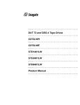
Make sure that the autoloader is turned off; then set the SCSI ID using the push-button switch on the
back of the autoloader. The following figure shows this switch, as well as the two SCSI interface
connectors, on/off switch, and the power cord connector.
NOTE: The autoloader must be restarted for any change in SCSI ID to take effect.
17
Installing the Autoloaders
Installing the Desktop Autoloader
68 pin wide
68 pinSCSI
wide
SCSI
connectors
connectors
AC
Power
connector
AC Power
connector
SCSI
connector
SCSI IDID
connector
On/Off
switch
On/Off switch
Figure 2. Autoloader Rear Panel
Connecting the SCSI Interface Cable
Your autoloader provides two (2) High-Density 68-pin, shielded connectors on the rear panel of the
enclosure. Either connector can be used as a SCSI IN or SCSI OUT connection (you can use either
connector to attach the autoloader to the host computer or to another SCSI device).
Turn off your computer and all SCSI devices. Then attach a SCSI cable from the host adapter or from
another (unterminated) SCSI device to the autoloader.
NOTE: This autoloader will not work in a SCSI-1 environment.
18
Installing the Autoloaders
Installing the Desktop Autoloader
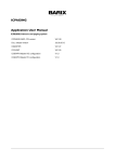
Installing SCSI Termination
If the autoloader is the last device or the only device in a SCSI chain, you must install a terminating
plug on the unused SCSI connector. See the following figure for two SCSI termination examples.
External SCSI
Device
External Tape
Drive
External Tape
Drive
External SCSI
Device
SCSI Controller
(termination enabled)
Internal SCSI
Device
SCSI Controller
(termination enabled)
(termination enabled)
Example 1:
SCSI termination in a
system that has only
external SCSI devices.
Example 2:
SCSI termination in a
system that has both internal
and external SCSI devices.
Figure 3. SCSI Termination Examples
Connecting the Power Cord
Attach the power cord securely to the power connector on the back of the autoloader. The location
of the power connector on the autoloader is shown in Figure 2 and Figure 3.
19
Installing the Autoloaders
Installing the Internal Autoloader
Installing the Internal Autoloader
The following sections describe how to install an internal autoloader.
Internal Autoloader Installation Summary
The internal autoloader is installed horizontally in a 5.25-inch, full-height drive bay. Installing the
internal autoloader involves the following steps:
1.
Configuring the Internal Autoloader
2.
Mounting the Internal Autoloader
3.
Connecting the SCSI Interface Cable
4.
Installing SCSI Termination
5.
Connecting the Power Cord
Configuring the Internal Autoloader
The internal autoloader is configured using jumpers and DIP switches. Table 3 shows the default
configuration for the internal autoloader.
Table 3. Default Configuration (Internal Drive)
Parameter
Default Setting
Configuration Method
6
Jumpers
Parity Checking
Enabled
Jumpers
SCSI Termination Power
Disabled
Jumpers
Data Compression
Enabled
DIP switches
Media Recognition System
(MRS) Verification
Enabled
DIP switches
Power On Self Test (POST)
Diagnostics
Enabled
DIP switches
Windows 98 SE/ME/NT 4.0/
2000/XP/Windows Server 2003
DIP switches
SCSI ID
Host Operating System
If these default settings are appropriate for your computer, skip to “Mounting the Internal
Autoloader” on page 24.
20
Installing the Autoloaders
Installing the Internal Autoloader
Changing Jumper Settings
Jumpers on the back of the internal drive let you change the following drive settings (see Figure 4 ):
•
SCSI ID
•
Parity checking
•
SCSI termination power
NOTE. Power down the drive before changing jumper settings. Changes take effect when the
drive restarts.
Default
jumper
settings
shown
Default jumper
settings
shown
(SCSI
ID6,6,parity
paritychecking
checking
enabled,
(SCSI ID
enabled,
and
termination power disabled)
and termination power disabled)
Pins:
Pins:
1-2
1-2
3-4
3-4
5-6
5-6
7-8
7-8
9-10
9-10
11-12
11-12
Function:
Function:
SCSI
IDbit
bit00
SCSI ID
SCSI
IDbit
bit11
SCSI ID
SCSI
IDbit
bit22
SCSI ID
SCSI
IDbit
bit33
SCSI ID
Parity
checking
Parity checking
Termination
Power
Termination Power
SCSI ID=0
SCSI ID=8
SCSI ID=1
SCSI ID=9
SCSI ID=2
SCSI ID=10
SCSI ID=3
SCSI ID=11
SCSI ID=4
SCSI ID=12
SCSI ID=5
SCSI ID=13
SCSI ID=6
SCSI ID=14
SCSI ID=7
SCSI ID=15
ID=0
Parity enable
Term. Power
Figure 4. Jumper Pins on the Back of the Internal Autoloader
SCSI Address Selection (pins 1 through 8)
21
Installing the Autoloaders
Installing the Internal Autoloader
Each SCSI device on a SCSI bus must have a unique SCSI ID. The SCSI controller or host adapter
generally uses ID 7. In some systems, the boot drive uses ID 0 or ID 1.
You can select an appropriate SCSI address for the drive by placing the appropriate jumpers on pin
pairs 1-2 through 7-8, as shown in Figure 4 on page 21 .
NOTE: SCSI ID numbers 8 through 15 will only be recognized if DIP switch 9 is “ON.” See
“SCSI Wide/Narrow (switch 9) - DDS-4 autoloader only” on page 24 for more information.
Parity Checking (pins 9 and 10)
If a jumper is installed on pins 9 and 10, parity checking is enabled. If no jumper is installed, parity
checking is disabled, but parity is still generated by the drive.
Terminator Power (pins 11 and 12)
If a jumper is installed on pins 11 and 12, terminator power is enabled.
NOTE: The internal autoloader drive does not provide SCSI termination, and therefore should
not be installed as the last device in a SCSI chain. See ““Installing SCSI Termination” on
page 19 for more information.
If the terminator power jumper is installed, be careful not to short the TERMPWR signal to ground. In
the event of a short, terminator power to the bus will be interrupted. After the short is removed, a
fuse in the drive will automatically reset, restoring terminator power.
Changing DIP Switch Settings
DIP switches on the underside of the internal autoloader let you change the following drive settings
(see Figure 5 on page 23 ):
•
Data compression
•
MRS checking (DDS-4 autoloader only)
•
POST diagnostics
•
Operating system settings
•
Wide/Narrow SCSI selection
•
Inquiry string
NOTE. Power down the drive before changing DIP switch settings. Changes take effect when the
drive restarts.
22
Installing the Autoloaders
Installing the Internal Autoloader
1
2
3
4
5
6
7
8
9
10
O
O
N
N
Data
Data compression
compression(DC)
(DC)
SCSI
SCSI DC
DCcontrol
control
Media
Media recognition
recognition
Self
Self Test
Test
Operating-system
Operating-system
configuration
configuration
switches
switches
Wide/Narrow SCSI
Wide/Narrow
SCSI
Inquiry String
Inquiry
Stringsupport
support
Default
Defaultsettings
settingsshown
shown
Figure 5. DIP-Switch Settings for the Internal Autoloader
Data Compression (switches 1 and 2)
Switch 1 enables or disables hardware data compression. Switch 2 determines whether SCSI
commands can be used to enable or disable hardware data compression.
•
Switch 1 ON:
Hardware data compression is enabled when drive is powered on. (default)
•
Switch 1 OFF:
Hardware data compression is disabled when drive is powered on.
•
Switch 2 ON: SCSI commands can be used to enable or disable hardware data
compression (default)
•
Switch 2 OFF: SCSI commands cannot be used to enable or disable hardware data
compression
Media Recognition System (switch 3) - DDS-4 autoloader only
The Media Recognition System (MRS) allows the drive to determine whether a given tape cartridge
conforms to the DDS tape standard. Switch 3 determines how the drive works with MRS and nonMRS media. Using non-DDS media may appear to give satisfactory results, but the inferior
specifications of such media can cause data-integrity problems.
•
Switch 3 ON: Drive reads from and writes to MRS media, and reads from but does not write
to non-MRS media (default)
•
Switch 3 OFF:
Drive reads from and writes to both MRS and non-MRS media.
Power On Self Test Enable/Disable (switch 4)
Switch 4 enables or disables execution of Power On Self Test (POST) diagnostics when the drive is
powered on.
•
Switch 4 ON: Drive performs POST when powered on. (default)
•
Switch 4 OFF: Drive does not perform POST when powered on.
23
Installing the Autoloaders
Installing the Internal Autoloader
Operating System configuration (switches 5 through 8)
Switches 5 through 8 configure the drive for use with UNIX, Novell, and Windows NT operating
systems. These procedures are described in Chapter 6, “Configuration for Novell and UNIX” on
page 44. The default setting for these switches is ON.
SCSI Wide/Narrow (switch 9) - DDS-4 autoloader only
Switch 9 enables or disables SCSI Wide operation on the SCSI bus.
•
Switch 9 ON: Drive can operate in Wide (16-bit) SCSI mode. (default)
•
Switch 9 OFF: Drive can only operate as a Narrow (8-bit) SCSI device.
NOTE: If switch 9 if set to OFF, the drive can only use SCSI ID values 0 through 7.
Inquiry String (switch 10)
Switch 10 selects the Vendor ID that the drive returns when queried with a SCSI Inquiry command.
•
Switch 10 ON:
Vendor ID is “SEAGATE DAT.” (default)
•
Switch 10 OFF: Vendor ID is “ARCHIVE Python.” This ID can be used by independent software
vendors to provide software compatibility with previous Seagate DDS tape drives.
Mounting the Internal Autoloader
The internal autoloader drive is mounted horizontally in a 5.25-inch, full-height drive bay. Mount the
drive using four M3.0 metric screws on the sides or bottom of the drive, as shown in Figure 6 on
page 25 . Do not use screws longer than 4 mm or you may damage the drive.
NOTE. When mounting the drive, make sure that nothing blocks the exhaust fan or the
ventilation slots on the bottom and rear of the autoloader.
24
79.5 ± 0.25
203.2 ± 0.25
82.6 ± 0.6
11.9 ± 0.3
45.5 ± 0.25
7.0 ± 0.3
21.8 ± 0.3
Installing the Internal Autoloader
1.8 ± 0.25
86 ± 0.25
Installing the Autoloaders
MOUNT HOLE
M3 (4 PLACES)
45.5 ± 0.25
79.5 ± 0.25
146 +1.5 –0.5
139.7 ± 0.3
149.6 ± 0.25
1.8 ± 0.25
224.0 max
MOUNTING HOLE
M3 (4 PLACES)
203.2 ± 0.5
224.0 max
Figure 6. Locations of Mounting Holes
Connecting the SCSI Interface Cable
Turn off all power to your computer and drive. Then connect a 68-pin wide internal SCSI cable from
your SCSI controller to the SCSI connector on the back of the autoloader. Be sure pin 1 on the SCSI
controller and cable is connected to pin 1 on the drive. Figure 7 on page 26 shows the location of
SCSI pin 1 on the drive’s SCSI connector. Pin 1 on the SCSI cable should be indicated by a colored
stripe.
The internal autoloader drive can be used with two types of SCSI interfaces:
•
Ultra2 SCSI (LVD)
•
“Wide” (16-bit) single-ended SCSI
The drive can automatically detect whether it is connected to an LVD or single-ended wide SCSI bus.
NOTE: The internal autoloader will not operate properly in a SCSI-1 environment.
25
Installing the Autoloaders
pin 34
34
pin
Installing the Internal Autoloader
pin
pin 1
1
pin 68
68
pin
Ultra2
SCSI
68-pin
highUltra2
SCSI
68-pin
density connector
high-density
connector
pin
pin 35
35
Power connector
Power
connector
pin 44
+5V
+5V
pin
pin 1
1
12V
12V
pin 3:
3: GND
GND
pin
(+5V
(+5V return)
return)
pin
pin2:2:GND
GND
(+12V
(+12V return)
return)
Figure 7. Interface Connectors on the Internal Autoloader
Installing SCSI Termination
The internal autoloader does not provide SCSI termination. For this reason, it should not be the last
device on a SCSI chain. However, if the drive is the only SCSI device, attach the drive to the
connector which is next to last on the SCSI chain and attach an LVD/single-ended multi-mode
terminator to the last connector in the chain. Two termination examples are shown in Figure 8 on
page 26 .
SCSI Device
SCSI Terminator
(termination enabled)
Internal Tape
Drive
Internal Tape
Drive
(no
termination)
(no
termination)
SCSI Device
(termination
disabled)
SCSI Device
(termination
disabled)
SCSI Controller
SCSI Controller
(termination enabled)
(termination enabled)
Figure 8. Two SCSI Termination Examples for the Internal Autoloader
26
Installing the Autoloaders
Installing the Internal Autoloader
Connecting the Power Cord
Attach a 5/12-volt, four-pin power cable to the power connector on the back of the drive. Figure 7
on page 26 shows the location of the power connector.
The recommended 4-pin power connector for the internal drive is an AMP 1-48024-0 housing with
AMP 60617-1 pins or equivalent.
27
4. Operating Your Autoloader
This chapter describes how to operate your autoloader.
Topics in this chapter are:
•
“Using the Appropriate Media” on page 28
•
“Starting the Autoloader” on page 29
•
“Applying Labels” on page 30
•
“Loading a Cartridge” on page 30
•
“Ejecting a Cartridge or Magazine” on page 31
•
“Write-Protecting a DAT Cartridge and Magazine” on page 33
•
“Cleaning the Tape Path” on page 34
•
“Preparation for Shipping” on page 35
Using the Appropriate Media
The DDS-4 and DAT 72 autoloaders are designed to use datagrade DAT cartridges, such as those
listed below.
NOTE: 60-meter DAT cartridges cannot be used with these autoloaders. The use of 90-meter
DAT cartridges is not recommended for these products.
Table 4. Matching Drives with the Media They Support
Media
Tape Length
DDS-4 Drives
DAT 72 Drives
DDS-2
120 meters, 4-Gbyte
uncompressed capacity
P
DDS-3
125 meters, 12-Gbyte
uncompressed capacity
P
P
DDS-4
150 meters, 20-Gbyte
uncompressed capacity
P
P
DAT 72
170 meters, 36-Gbyte
uncompressed capacity
P
28
Operating Your Autoloader
Starting the Autoloader
Starting the Autoloader
Turn on all external SCSI devices attached to your computer before you turn on the computer. When
the autoloader is first started, the following events should occur:
1.
The Clean, Media, and Drive LED’s light up for two seconds, then start flashing.
2.
The LCD display shows the current SCSI ID.
3.
If a magazine is loaded, the LCD display shows the message “SCAN X” while the autoloader
determines which slots in the magazine contain cartridges.
4.
As each cartridge is identified by the autoloader, the cartridge’s slot number is displayed on
the LCD. If there is no cartridge in a slot, the slot number will not be displayed.
5.
When all tests are completed, the LCD display shows the message “READY” if a magazine is
loaded. If no magazine is loaded, the message “NO MAGAZINE” is shown.
NOTE: If your computer does not recognize the autoloader, you may need to load the
appropriate autoloader module for your backup software. See your backup software installation
manual for additional information.
Handling Cartridges
To protect your data cartridges and the information on them, observe the guidelines and avoid the
pitfalls in the following table.
Table 5. Cartridge Guidelines and Pitfalls
Guidelines to Follow...
Pitfalls to Avoid
Use DAT cartridges at temperatures from 5° C (40° F)
to 40° C (104° F). Cartridges can be stored at
temperatures down to -40° C (-40° F).
Do not expose cartridges to direct sunlight, moisture,
excessively dry or humid places, extreme changes in
temperature or humidity, or X-rays.
Handle cartridges gently.
Do not treat cartridges roughly or drop them.
Keep cartridges in plastic cases when they are not in
use.
Do not try to clean the tape guides or tape path
inside the cartridge.
Apply just one label to the designated area on the
cartridge. Affixing more labels can jam the drive.
Never touch the exposed tape media with your
fingers.
If your data is important, consider reading data off of
tapes and rewriting to new and perhaps more
modern tapes every few years.
Never leave cartridges close to magnetic fields, such
as near a monitor or telephone handset.
If cartridges are exposed to temperatures or
humidities outside the specified operating
environment, expose them to the operating
environment for a time equal to the period that the
cartridges were exposed to the out-of-specification
environment (up to a maximum of 24 hours).
Do not read from or write to cartridges when a
temperature change of 10° C per hour is occurring.
29
Operating Your Autoloader
Applying Labels
Applying Labels
When applying labels to a cartridge, observe the following precautions to prevent the cartridge
from getting stuck in the autoloader:
•
Apply labels firmly, only in recessed label areas on the top side of the cartridge.
•
Do not let labels extend beyond label areas or fold over the edge of a cartridge.
•
Do not apply labels over other labels.
CAUTION: Do not place any labels on the autoloader magazine, since this may cause the tape
mechanism to jam.
Loading a Cartridge
Use only approved DAT cartridges in the autoloader. To load cartridges into the magazine, follow
these steps:
1.
Make sure that the cartridges are write-protected or write enabled, as necessary. For more
information, refer to “Write-Protecting a DAT Cartridge and Magazine” on page 33.
2.
Hold the magazine so that the slot numbers on the side of the magazine are right-side-up.
3.
Insert cartridges with the cartridge door facing the magazine slot, as shown in the following
figure.
Figure 9. Loading a Cartridge into the Autoloader Magazine
30
Operating Your Autoloader
Ejecting a Cartridge or Magazine
Loading a Magazine into the Autoloader
CAUTION: Do not load a magazine if all the LED’s are flashing; this indicates that the
autoloader is performing a Power On Self Test (POST).
1.
Make sure the autoloader is powered on and operating normally.
2.
Hold the magazine so that the slot numbers are right-side-up.
3.
Write-protect or write-enable the magazine as appropriate. For more information, refer to
“Write-Protecting a DAT Cartridge and Magazine” on page 33.
4.
Insert the magazine into the autoloader with the triangles facing into the autoloader bay, as
shown below. Gently push the magazine into the autoloader bay until the autoloader
mechanism senses the magazine and pulls it inside.
Figure 10. Loading a Magazine into the Autoloader
Ejecting a Cartridge or Magazine
To eject the magazine from the autoloader, press the Eject button. If the drive mechanism contains a
cartridge, the LCD display shows the message “EJECT? PRESS ENTER”. Press the Enter button, and
wait for the following events to complete:
1.
The tape rewinds to the beginning-of-partition (BOP) mark.
2.
If the data cartridge is not write-protected, the operating system writes the updated copy of the
tape log back to the tape.
3.
The tape rewinds to the beginning-of-media (BOM) and is unthreaded.
4.
The changer places the cartridge back into the magazine.
31
Operating Your Autoloader
5.
Ejecting a Cartridge or Magazine
The magazine is ejected.
If there is no cartridge loaded in the autoloader mechanism, the magazine is ejected without delay.
Forcing an Eject
If you press the Eject button when the autoloader is busy, the autoloader will complete the current
task before responding to the eject request. This way no data is lost.
However, in extreme cases, you may need to force an eject operation to unload a cartridge, even at
the risk of losing the data on the cartridge. A forced eject should only be tried when there is no other
way to recover a cartridge.
CAUTION: If you force an eject, the cartridge may become unreadable and therefore require
erasing or re-initialization by the application software.
To force an eject, hold down the Eject button for at least five seconds, then release the button. When
you force an eject, the following occurs:
If there is a cartridge loaded, the Status Panel displays the message “UNLOAD TAPE X” (where X is
the number of the magazine slot which held the cartridge currently in the autoloader). After the
cartridge has been returned to the magazine, the display changes to “EJECTING MAGAZINE” and
the magazine is ejected.
NOTE: Because forcing an eject can interrupt an operation, the autoloader might not write the
end of data (EOD) mark on the tape before the cartridge is ejected. If the EOD mark is not
written on the tape, the cartridge might be formatted incorrectly and the data on the tape might
be lost. However, the data can usually be read up to the point where the error occurred.
Automatic and Manual Cartridge Loading
After cartridges have been loaded into the magazine and the magazine has been inserted into the
magazine bay, the autoloader can be left indefinitely for unattended write or read operations
(controlled by your backup software).
To load a cartridge manually, press the SELECT button repeatedly until the desired slot location is
identified, then press the ENTER button.
32
Operating Your Autoloader
Write-Protecting a DAT Cartridge and Magazine
Write-Protecting a DAT Cartridge and
Magazine
Write-protecting a DAT cartridge protects the data on the cartridge from being changed,
overwritten, or deleted. To write-protect a cartridge, slide the write-protect tab on the back of the
cartridge to the open position. To write-enable the cartridge, slide the write-protect tab so the hole is
closed.
Write
enabled
Write enabled
Write
protected
Write protected
Figure 11. Write-protecting a DAT Cartridge
The following figure shows how to write-protect a magazine. To enable writing to the magazine,
move the switch upward. To protect all cartridges in the magazine from being written to, move the
switch down.
Write-enabled
Write
enabled
Write-enabled
Write-disabled
Write-disabled
Figure 12. Write-protect switch on autoloader magazine
33
Operating Your Autoloader
Cleaning the Tape Path
Cleaning the Tape Path
If excessive magnetic dust or debris collects at one or more of the tape heads, the autoloader may
not be able to read from or write to tape, or may experience excessive errors. When the cleaning
threshold is exceeded, the autoloader will display the cleaning request in two ways:
•
The LCD display will show the message “CLEANING REQUIRED.”
•
The Clean LED will remain ON continuously.
NOTE: A slowly flashing Clean LED may indicate that a tape is damaged or is nearing the end
of its life. If cleaning the tape path does not correct the flashing LED condition, replace the
cartridge.
Table 6. Cleaning the Autoloader
Daily Usage
(hours).
Optimum Cleaning
Frequency
0-4
Three times per month
4-8
Weekly
8-12 or more
Twice a week
Cleaning Procedure
To clean the tape heads on your DAT 72 and DDS-4 autoloader, use only a Certance-approved
cleaning cartridge. You can purchase a Certance DDS Cleaning Cartridge on the internet at: http:/
/shop.certance.com (U.S. only).
NOTE: The autoloader cannot recognize audio DAT cleaning cartridges.
Manual Cleaning
You can clean the autoloader manually using the following procedure:
1.
Place the cleaning cartridge in a magazine slot and insert the magazine into the autoloader.
2.
Use the Select button to select the slot where you placed the cleaning cartridge.
3.
Press the Enter button to load the cleaning cartridge into the autoloader. The autoloader starts
the cleaning cycle automatically.
4.
When the cleaning cycle is complete, the cartridge will automatically eject. If the cartridge is
not automatically ejected, press the Eject button to return the cleaning cartridge to the
magazine. Press the Eject button again to unload the magazine and remove the cleaning
cartridge.
5.
Record the date of the cleaning on the cleaning cartridge label.
34
Operating Your Autoloader
Preparation for Shipping
Each time the cleaning cartridge is loaded, a new, unused portion of cleaning tape is advanced
over the entire tape path. The drive does not rewind a cleaning cartridge. After about 30 cleaning
cycles, the entire tape is used up, and you must purchase a new cleaning cartridge.
If you insert a cleaning cartridge that has been used up, the cleaning cycle will not be carried out.
Instead, the Clean LED will flash rapidly and the LCD will display the message, “REPLACE
CLEANING TAPE.” The cleaning cartridge will not be returned to the magazine, the Clean LED will
stay on, and the LCD will display the message, “CLEANING REQUIRED.” In this case, press the Eject
button to remove the magazine and replace the spent cleaning cartridge with a new one.
Automated Cleaning
If your backup-and-restore software includes a tape drive head-cleaning feature, you can use the
software to clean the autoloader. Some software packages are preprogrammed to use the cartridge
in slot 6 to clean the tape path automatically. The software prompts the autoloader to load the
cleaning cartridge and initiate the cleaning cycle. When the cleaning cycle completes, the tape
drive ejects the cleaning cartridge and automatically returns it to the original magazine slot. Refer to
your software documentation for details.
If, during automated cleaning, a cleaning cartridge is loaded that has been used up, the cleaning
cycle will be aborted. Instead, the LCD will display the message “REPLACE CLEANING TAPE”, and
the cleaning cartridge will be returned to the magazine. The Clean LED will stay lit, and the LCD will
display the messages “REPLACE CLEANING TAPE” and “CLEANING REQUIRED”. After the software
operations are complete, you may use the Eject button to remove the spent cleaning cartridge and
insert a new one.
Preparation for Shipping
Before shipping the autoloader, you must secure the autoloader door to prevent damage to the
device. Follow the procedure below to secure the door as the last step before switching off the
autoloader:
1.
Make sure there is no magazine in the autoloader. The LCD should display the message “NO
MAGAZINE.”
2.
Press and hold the Select button for 5 seconds. The LCD should show the following menu:
>VERSION
LANGUAG
CONTRAST
3.
Press the Select button four times. The cursor (>) will move down to the word “DOOR,” as
shown below:
CONTRAST
AUTO/LD
>DOOR
4.
Press the Enter button. The LCD should display the following sub-menu:
DOOR
>LOCK
UNLOCK
5.
Press the Select button once to move the cursor to “LOCK” and then press the Enter button. The
display returns to the menu shown in step 3 above.
35
Operating Your Autoloader
Preparation for Shipping
6.
Wait 5 seconds. The LCD screen will again display the message “NO MAGAZINE.” After
another 5 seconds, the LCD will display the message, “DOOR LOCKED.”
7.
Switch off the autoloader.
8.
Tap the door to make sure it has been successfully locked.
The door is now locked in the closed position and the autoloader is ready to be packed and
shipped. The door is automatically unlocked when the autoloader is restarted.
36
5. Understanding the Drive LEDs
This chapter describes the LEDs on the front panel of the DDS-4 and DAT 72 autoloader. These LEDs
provide information about both normal and error conditions.
Topics in this chapter are:
•
“Front Panel LEDs” on page 37
•
“LED Summary” on page 38
•
“Clean LED” on page 39
•
“Media LED” on page 39
•
“Drive LED” on page 40
•
“About the Operator Panel LCD Display” on page 41
Front Panel LEDs
The following figure shows an example of the LEDs on the drive front panel of the DDS-4 and DAT
72 autoloaders.
EJECT
EJECT
button
button
SELECT
SELECT
button
button
ENTER
ENTER
button
button
Clean
Clean
LED
LED
(green)
(green)
Media
Drive
LED
Media
Drive LED
LED
(amber)
LED
(amber)
(green)
(green)
LCD
LCD
Display
Display
Figure 13. Front Panel LEDs
37
Understanding the Drive LEDs
LED Summary
Eject Button
You can use the Eject button to eject the magazine or to unload a cartridge from the drive. After
pressing the Eject button, you must press the Enter button to confirm your request.
Select Button
You can use the Select button to select individual cartridges by their slot numbers (1 through 6), to
scroll through items from menus on the LCD display, and to access loader menus if no magazine is
installed.
Enter Button
You can use the Enter button to select specific items from menus on the LCD display, to load a
cartridge into the autoloader (after you have selected the cartridge using the Select button), or to
confirm that you want to eject the magazine when there is a cartridge in the autoloader
LED Summary
The following table summarizes the actions of the front-panel LEDs.
Table 7. LED Quick Summary
LED
Color
Action
Description
Clean
Green
ON (Lit)
Cleaning is required because the autoloader has been
operating for at least 25 hours (DDS-2) or 50 hours
(DDS-3, DDS-4, or DAT 72).
Slow Flashing
Internal error rate threshold has been exceeded and
cleaning is required.
Flashing
Cleaning cartridge in the drive has exceeded its useful
life. Replace the old cleaning cartridge with a new one.
ON (Lit)
An inserted cartridge is operating properly.
Flashing
Drive could not write the tape correctly (write error).
Use a DDS cleaning cartridge to clean the drive.
ON (Lit)
Drive is reading or writing the tape normally.
Rapid Flashing
A hardware fault has occurred.
Media
Drive
Green
Amber
38
Understanding the Drive LEDs
Clean LED
Clean LED
The Clean LED indicates whether a drive needs to be cleaned.
Table 8. Clean LED
LED Status
Description
ON continuously
Drive requires cleaning. Use only an approved DDS cleaning cartridge.
Flashing slowly (approximately Tape cartridge in use has exceeded a predefined soft-error threshold.
ON 2 seconds, OFF 1 second) This signal is a warning only and does not indicate that data has been
compromised. Remove the tape and clean the drive using an approved
DDS cleaning cartridge. If the Clean LED still flashes after cleaning and
reinserting the original data cartridge, use a new cartridge for future
backups.
Flashing rapidly
A cleaning cartridge that has exceeded its useful life has been inserted
into the drive. Replace the cleaning cartridge with a new approved
DDS cleaning cartridge.
Media LED
The Media LED indicates whether a DAT cartridge is operating normally.
Table 9. Media LED
LED Status
Description
ON continuously
A DAT cartridge has been inserted and the drive is operating normally.
Flashing rapidly
Drive could not write the tape correctly (maximum rewrite count
exceeded) and the write operation failed. Clean the drive heads using
an approved DDS cleaning cartridge. If you reinsert the original data
cartridge and the LED continues flashing, insert a new data cartridge
and retry the operation.
NOTE: As routine maintenance, follow the cleaning recommendations listed in Table 5.
39
Understanding the Drive LEDs
Drive LED
Drive LED
The amber Drive LED lets you know when data is being read from or written to tape. It also informs
you when a hardware fault occurs.
Table 10. Drive LED
LED Status
Description
ON continuously
The drive is reading or writing the tape (SCSI or tape movement is
present).
Flashing rapidly
A hardware fault occurred. If the fault occurs immediately after
powering on the drive, the Power On Self Test (POST) switch (switch 4)
is enabled and a POST has failed. If the front panel LEDs are flashing
together, contact the Technical Support department.
If the Drive LED is flashing rapidly during drive operation, press the
Eject button to remove the tape. If the tape does not eject within 2
minutes, press and hold the Eject button for more than 5 seconds. The
tape should eject within 40 seconds. Contact Technical Support for
more information.
CAUTION: If you push the Eject button while the Drive LED is ON, you will interrupt any host
operation, causing an application error. It may not be possible to append to the tape if a write
operation is aborted in this way.
NOTE: If your backup software issues a SCSI “Prevent Media Removal” command, the Drive
LED remains ON and the Eject button is disabled, so that the tape cannot be ejected
accidentally. To eject the tape, use your backup software’s Eject command.
40
Understanding the Drive LEDs
About the Operator Panel LCD Display
About the Operator Panel LCD Display
The following figure shows the types of information shown on the operator panel LCD display.
Indicates whether
active cartridge or
magazine is writeprotected
Indicates slot
number of active
cartridges
LINE
LINE
LINE
11
22
Bar graph indicating
current position of
tape head relative to
beginning of
partition
Indicates whether
data-compression
is active
Message display
Indicates whether
tape is in motion
Figure 14. LCD display features
LCD Display Backlighting
Backlighting on the LCD display is turned on automatically when the autoloader is first powered on
and whenever an operator panel button is pushed. The backlight remains on for two minutes, and
then shuts off automatically (unless an operator panel button is pressed).
LCD Display Messages
The table on the following pages describes the messages that may be shown on the LCD display. The
messages are listed in alphabetical order. An “X” indicates the number of the currently active
cartridge slot.
LCD Message
Description
CASSETTE INSTALL PROBLEM
A cartridge has been inserted into the magazine incorrectly. Eject the
magazine from the autoloader; then remove the cartridge from the
magazine and reinsert it correctly.
CHECK DOOR
The autoloader door is open.
CLEANING
The autoloader is loading a cleaning cartridge into the drive.
CLEANING REQUIRED
The tape drive mechanism requires cleaning.
DOOR LOCKED
The autoloader door is locked.
DOOR UNLOCKED
The autoloader door is unlocked.
41
Understanding the Drive LEDs
About the Operator Panel LCD Display
LCD Message
Description
DRIVE ERROR04/XX/XX
There is a problem with the autoloader. For additional information,
contact Certance Technical Support.
ERASE TAPE X
The tape drive is erasing the data cartridge from slot X.
EJECTING MAGAZINE
The autoloader is ejecting the cartridge magazine.
EJECT? PRESS ENTER
A cartridge resides in the drive and the Eject button has been pressed.
Eject confirmation is required before the cartridge can be ejected.
EJECT PREVENT
The autoloader is preventing you from ejecting the magazine because
the software has enabled PMR (Prevent Media Removal).
FAN FAILURE
There is a problem with the autoloader fan.Contact Certance Technical
Support.
INSERT EMPTY MAGAZINE
The autoloader cannot unload a cartridge from the tape drive to the
magazine because the magazine in the autoloader is fully loaded. Eject
the magazine; then insert an empty magazine into the autoloader
LOADER ERROR04/XX/XX
There is a problem with the autoloader hardware. For additional
information, contact Certance Technical Support.
LOAD TAPE X
The tape drive is loading the cartridge from slot X.
MEDIA ERROR03/XX/XX
There is a problem with the data cartridge. For additional information,
contact Certance Technical Support.
NO MAGAZINE
There is no magazine in the autoloader.
READ TAPE X
The tape drive is reading from a data cartridge.
READY
The autoloader has scanned all cartridge slots in the magazine and is
ready to perform an action.
READY TAPE X
There is a cartridge (from slot X) in the tape drive and the autoloader is
ready to accept commands.
REPLACE CLEANING TAPE
The cleaning cartridge has been used up and must be replaced with a
new cleaning cartridge.
REWIND TAPE X
The tape drive is rewinding the data cartridge from slot X.
SCAN X
The autoloader is sequentially scanning the cartridge slots in the
magazine.
SEARCH TAPE X
The tape drive is searching the data cartridge from slot X.
SELECT XPUSH ENTER
This message displays when the Select button is pressed. Press the
Select button repeatedly to display the desired cartridge location
number (X); then press the Enter button to load the selected cartridge
into the drive.
SELECT PREVENT
The autoloader is prevented from ejecting the magazine because the
software has enabled PMR (Prevent Media Removal). Use your backup
software to eject the tape, then press the Eject button to eject the
magazine.
UNLOAD TAPE X
The tape drive is unloading the cartridge from slot X.
UPDATING FIRMWARE
The autoloader firmware is being updated.
WAITING SELF TEST
This message displays while the autoloader is performing a POST
during startup.
WRITE TAPE X
The tape drive is writing to the data cartridge from slot X.
42
Understanding the Drive LEDs
About the Operator Panel LCD Display
Configuring Autoloader Features Using the LCD Display
To configure the autoloader using the LCD, first make sure that there is no magazine installed in the
autoloader; then press and hold the Select button for five seconds. You can then use the Select button
to cycle through the following menus: VERSION, LANGUAG (Language), CONTRST (Contrast),
AUTO/LD (Auto Load), and DOOR. Each of these is described below. To display a particular menu,
select the menu item and press the Enter button.
Version Menu
In the VERSION menu, you can use the Select button to view the name of the autoloader, its SCSI ID,
its firmware level, and the autoloader serial number.
Language Menu
In the LANGUAG menu, you can enable the autoloader to display messages on the LCD in English,
French, German, Italian, Portuguese, Japanese, or Spanish by scrolling to the appropriate language
and pressing the Enter button.
Contrast Menu
In the CONTRST menu, you can make the LCD display brighter by pressing the Enter button
repeatedly until the desired contrast is displayed. To make the LCD darker, press the Select button
repeatedly until the desired contrast is displayed.
Autoload Menu
In the AUTO/LD menu, you can enable or disable automatic loading of cartridges from the
magazine into the tape drive.
NOTE: This feature should only be used to automate cartridge loading if application software to
support the loader operation is not available.
Most software available for the Windows NT/2000 platform does support the SCSI commands
necessary for loader operation. In this environment we suggest leaving automatic load disabled
(the default state). Check with your software vendor if you are unsure about your particular
software application.
In Unix/Linux environments backup software may not support autoloader operation directly. In
this case, the 'offline' command is used to change cartridges sequentially (in numerical order by
slot number). In Unix/Linux environments, enabling automatic cartridge loading can allow you
to setup an unattended backup.
To enable cartridge autoloading from within the autoload menu, select “ON” and then press the
Enter button. After the magazine is inserted, cartridge 1 will automatically be loaded into the drive.
When autoloading is enabled, the Select button can still be used to exchange cartridges, but only in
a sequential manner (in numerical order, by slot number).
To turn off autoload mode, display the autoload menu, select “OFF”, and then press the Enter button.
When autoloading is disabled, cartridges can only be loaded or unloaded via the operator panel or
using application software that has autoloader support.
Door Menu
In the DOOR menu, you can lock the autoloader door by selecting “LOCK” and pressing the Enter
button. You can unlock it by selecting “UNLOCK” and pressing the Enter button.
43
6. Configuration for Novell and UNIX
This section explains how to configure the DAT 72 and DDS-4 autoloader for use with various Novell
and UNIX operating systems.
Topics in this chapter are:
•
“Operating System Configuration” on page 44
•
“Configuration for Novell Environment” on page 45
•
“Configuration for DEC UNIX Environment” on page 45
•
“Configuration for Sun UNIX Environment” on page 47
•
“Configuration for SGI Environment” on page 48
•
“Troubleshooting Installations on the SGI Platform” on page 50
•
“Configuration for HP-UX Environment” on page 50
•
“Configuration for IBM AIX Environment” on page 51
•
“Configuration for SCO UNIX” on page 52
•
“Configuration for LINUX” on page 52
Operating System Configuration
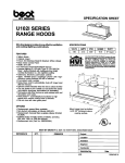
The following figure shows the location of the operating system configuration DIP switches (switches
5 through 8) on the underside of the autoloader.
NOTE: If the autoloader is to be used with an operating system other than those described here,
these switches should be left in their default positions.
44
Configuration for Novell and UNIX
1
2
3
4
5
6
7
8
9
10
Operating System Configuration
O HW data comp
N SW data comp
Media recognition system
Power ON self test
Operating system
configuration
switches
Wide/Narrow SCSI
Inquiry String support
Default settings shown
Figure 15. Operating System DIP Switches
Configuration for Novell Environment
There are two possible ways to configure the DAT 72 and DDS-4 autoloader to work with the
NetWare native backup application, depending on which tape driver you use.
Configuration 1: If you are using the original Novell NWTAPE driver or any version created before
11/3/99, you must change the Operating System Configuration DIP switches so that switches 5
and 8 are OFF. This is different from their default settings (switches 5 through 8 ON).
Configuration 2: If you use the latest Novell NWTAPE driver (available on the Novell web site), the
Operating System Configuration DIP switches can be left in their default positions (switches 5
through 8 ON).
Configuration for DEC UNIX Environment
DIP Switch Settings
Before using the DAT 72 or DDS-4 autoloader in a DEC UNIX environment, set the operating-system
DIP switches as shown below:
Setting
S5
S6
S7
S8
S10
OFF
ON
ON
ON
ON
45
Configuration for Novell and UNIX
Operating System Configuration
Digital UNIX Version 4.0 and Later
With Version 4.0 of the Digital UNIX operating system, DEC introduced a new method of
configuring the CAM SCSI driver. Modify the file /etc./ddr.dbase as follows:
1.
Look through the file and locate the database entry for the DEC TLZ07 DAT drive
2.
Copy this entry and paste it later in the file, taking care to maintain the file syntax.
3.
Modify this new entry as shown below.
SCSIDEVICE
#
Type = tape
Name = “ARCHIVE Python” “DAT”
#
PARAMETERS:
TypeSubClass
TagQueueDepth
MaxTransferSize
ReadyTimeSeconds
=
=
=
=
rdat
0
0x0ffffff
60
# (16MB - 1)
# seconds
DENSITY:
#
DensityNumber = 0,3,4,5,6,7
DensityCode = default
CompressionCode = 0x0
Buffered = 0x1
DENSITY:
#
DensityNumber = 1,2
DensityCode = default
CompressionCode = 0x1
Buffered = 0x1
4.
Save the database file.
5.
Run the following command: ddr_config -c. This takes the default input file, ddr.dbase,
and builds a new device database. The new device database is effective immediately, and
there is no need to rebuild the kernel.
Digital UNIX Versions Earlier Than 4.0.
Configure the system by modifying the file cam_data.c. This is located in either /usr/sys/data or
/sys/data, depending on the system configuration. The cam_data.c file should be modified as
shown below:
1.
Look through the file to locate the database entry for the “TLZ07 – RDAT” drive.
2.
Make a copy of this entry and paste it later in the file, taking care to maintain the syntax of the
C source.
3.
Modify the new entry as shown below.
/* Iomega DAT Drive Returning “ARCHIVE Python DAT” Inquiry
*/
{“ARCHIVE Python DAT”, 14, DEV_TLZ07,
(ALL_DTYPE_SEQUENTIAL << DTYPE_SHFT) | SZ_RDAT_CLASS,
46
Configuration for Novell and UNIX
Operating System Configuration
(struct pt_info *)ccmn_null_sizes, SZ_NO_BLK, (DEC_MAX_REC - 1),
&tlz07_dens, NO_MODE_TAB, SZ_NO_FLAGS,
NO_OPT_CMDS, SZ_READY_DEF, SZ_NO_QUE,
DD_REQSNS_VAL | DD_INQ_VAL, 36, 64
},
4.
Rebuild the kernel using the doconfig script. Then reboot the system.
Configuration for Sun UNIX Environment
DIP switch settings
Before using the DAT 72 or DDS-4 autoloader in a Sun UNIX environment, set the operating-system
DIP switches as shown below:
Setting
S5
S6
S7
S8
S10
ON
OFF
ON
ON
OFF
Sun OS 4.1.x
To configure SunOS 4.1.x to use the DAT 72 or DDS-4 autoloader, you must modify the stdef.h
and st_conf.c files (in the directory /usr/sys/scsi/ targets), then rebuild the kernel, as
described below:
1.
Modify the stdef.h file by adding a define statement for the Iomega drive like the one shown
below:
#define ST_TYPE_ARCHIVE Python_DAT <value>
This statement should be added after the last ST_TYPE_ define statement in the file. <value>
should be the next unused hexadecimal value. This value will depend on the release and number of devices supported by the system. For example, if the last value for an existing device is
0x2d, then use a value of 0x2e.
2.
Modify the st_conf.c file by adding the following lines at the end of the device definition
list:
{
“ARCHIVE Python”,7,“ARCHIVE Python”,ST_TYPE_ARCHIVE_Python,10240,
(ST_VARIABLE|ST_BSF|ST_BSR|ST_LONG_ERASE|ST_KNOWS_EOD),
5000,5000,
{0x0,0x8c,0x8c,0x8c},
{0,0,0,0}
}
3.
Use the config command to rebuild the kernel and include the new device definition. Refer to
the config command page for details.
47
Configuration for Novell and UNIX
Operating System Configuration
Solaris 2.x
1.
To configure Solaris 2.x for compatibility with the DAT 72 or DDS-4, add the following lines to
the file st.conf in the directory /kernel/drv.
tape-config-list=
“ARCHIVE Python”,“Iomega DAT Drive”,“ARCHIVE Python DAT”;
ARCHIVE Python DAT = 1,0x34,0,0xd639,4,0x00,0x8C,0x8C,0x8C,3;
2.
After modifying the file st.conf, you must reconfigure the kernel by booting the system using
the boot -r command.
Configuration for SGI Environment
DIP Switch Settings
Before using the DAT 72 or DDS-4 autoloader in a SGI UNIX environment, ensure that the DIP
switches are set as shown in the following table:
Switch
5
Setting
ON
Switch
6
ON
Switch
7
ON
Switch
8
ON
Switch
10
OFF
NOTE: The main difference between tape autoloader support in Irix 5.x and 6.x is the
introduction of Data Compression switching via software in Irix version 6.2. When running Irix
5.x, the autoloader will operate in the compression setting determined by switches 1 and 2,
accessible through a removable panel on the bottom of the autoloader.
Irix V5.x
To configure Irix 5.x to use the DAT 72 and DDS-4 autoloader, you must modify the file /var/
sysgen/master.d/scsi as described below:
1.
Edit the file /var/sysgen/master.d/scsi and add the following entry:
{DATTAPE,TPDAT,7,3, “ARCHIVE
Python",“DAT"/*DAT*/,0,0,{0,0,0,0},
MTCAN_BSF|MTCAN_BSR|MTCAN_APPEND|MTCAN_SETMK|MTCAN_PART|MTCAN_
PREV|
MTCAN_SYNC|MTCAN_SPEOD|MTCAN_CHKRDY|MTCAN_VAR|MTCAN_SETSZ|
MTCAN_SILI|MTCAN_SEEK|MTCAN_CHTYPEANY,
/* minimum delay on i/o is 12 minutes, to allow the Drives
* full error recovery sequence to be performed. */
40, 12*60, 12*60, 12*60, 512, 512*512 }
2.
Rebuild the kernel using the autoconfig command (see the autoconfig man page for
details). After the kernel is rebuilt you will need to reboot the system again to bring the
changes into effect.
NOTE: Irix 5.3 and later will detect the changes made and automatically rebuild the kernel the
next time the system boots.
48
Configuration for Novell and UNIX
Operating System Configuration
Irix V6.x through V6.5
To configure Irix 6.x-6.5 to use a DAT 72 or DDS-4 autoloader, you must modify the files /var/
sysgen/master.d/scsi and /dev/MAKEDEV.d/TPS_base, as described below. After
modifying these files you must rebuild the kernel.
1.
Edit the file /var/sysgen/master.d/scsi and add one of the following entries,
depending on your version of Irix:
Irix V6.x through V6.4:
{ DATTAPE, TPDAT, 7, 3, “ARCHIVE Python”,“DAT”/*DAT*/, 0, 0, {0},
/* This drive uses mode select page 0xf for compression control;
* most of the other drives supporting compression use page 0x10 */
MTCAN_BSF|MTCAN_BSR|MTCAN_APPEND|MTCAN_SETMK|MTCAN_PART|MTCAN_PREV|
MTCAN_SYNC|MTCAN_SPEOD|MTCAN_CHKRDY|MTCAN_VAR|MTCAN_SETSZ|
MTCAN_SILI|MTCAN_SEEK|MTCAN_CHTYPEANY|MTCAN_COMPRESS,
/* minimum delay on i/o is 12 minutes, to allow the Drives
* full error recovery sequence to be performed. */
40, 12*60, 12*60, 12*60, 512, 512*512, 0, (u_char *)0 },
Irix V6.5:
{ DATTAPE, TPDAT, 7, 3, “ARCHIVE Python”,“DAT”/*DAT*/, 0, 0, {0},
/* This drive uses mode select page 0xf for compression control;
* most of the other drives supporting compression use page 0x10 */
MTCAN_BSF|MTCAN_BSR|MTCAN_APPEND|MTCAN_SETMK|MTCAN_PART|MTCAN_PREV|
MTCAN_SYNC|MTCAN_SPEOD|MTCAN_CHKRDY|MTCAN_VAR|MTCAN_SETSZ|
MTCAN_SILI|MTCAN_SEEK|MTCAN_CHTYPEANY|MTCAN_COMPRESS,
/* minimum delay on i/o is 12 minutes, to allow the Drives
* full error recovery sequence to be performed. */
40, 12*60, 12*60, 12*60, 512, 512*512,
tpsc_default_dens_count, tpsc_default_hwg_dens_names,
tpsc_default_alias_dens_names,
{0},0,0,0,
0, (u_char *)0 },
2.
Edit the file /dev/MAKEDEV.d/TPS_base and make the following modification (this
modification is not required on systems running IRIX 6.4 or 6.5).
Locate the area of code that deals with DAT drives. This starts with:
*Drive?type:*DAT*
Then insert the following text before or after the similar entries for other supported devices:
*Device:*DAT*06240*) # DAT drive with compression
mdev=`expr $mdev + 8`;
mknod ${prf}$1c c ${C_TPS} $mdev;
;;
3.
Restart the system. Irix 6.x will detect the changes made and automatically rebuild the kernel
on startup.
Alternatively, you could manually rebuild the kernel using the autoconfig command (see the
autoconfig man page for details), then reboot the system again.
49
Configuration for Novell and UNIX
Operating System Configuration
Troubleshooting Installations on the SGI Platform
Checking the Inquiry String
It may be useful to confirm the autoloader’s inquiry string. This is done using the mt command. The
following command line will retrieve the Inquiry string and other status data from the autoloader on
SCSI bus 1, ID 6.
mt -f /dev/rmt/tps1d6 status
System Interchange Problems
If the following error appears when trying to restore a cpio archive from another system, it is likely
that a mistake was made in the installation sequence:
Byte swapped Data - re-try with correct device
If this error is encountered, make sure that the correct modifications were made to the file /var/
sysgen/master.d/scsi.
Switching Compression
Irix 6.x provides support for software switching of data compression through the use of different
device drivers. Drivers including a “c” in the device name should enable compression. You may be
able to resolve problems with data compression by installing the latest Irix 6.x patch set.
Configuration for HP-UX Environment
DIP Switch Settings
Before using the DAT 72 or DDS-4 autoloader in an HP UNIX environment, set the operating-system
configuration DIP switches as shown below:
Setting
S5
S6
S7
S8
S10
ON
ON
OFF
ON
OFF
HP-UX Version 10.2 and 11
Follow the steps below to configure HP-UX systems:
1.
Log in as root.
2.
Run the SAM utility.
3.
Choose the Peripheral Devices option.
4.
Choose Tape Drives.
5.
From the Actions menu in the Tape Device Manager window, choose Add.
6.
Within the Add a Tape Drive window, read the instructions, then click on OK.
7.
SAM may detect that your HP-UX kernel lacks the drivers necessary to make use of your new
tape drive. If so, within the “Device Driver Check” window, read the message and choose the
appropriate action. If the chosen option is Build a new kernel and shut down the system
50
Configuration for Novell and UNIX
Operating System Configuration
immediately, SAM will create a new kernel, and automatically reboot the system. Once the
system comes back up, the necessary drivers will be loaded, and the system will be able to
use the tape drive.
8.
If you had to shut down the system in order to physically connect the tape drive, re-enter SAM
and repeat steps 3 through 6 above.
9.
Choose the new tape drive.
10. From the Actions menu, choose Create Device Files.
11. Press OK and then exit from SAM.
Configuration for IBM AIX Environment
DIP Switch Settings
Before using the DAT 72 or DDS-4 autoloader in an IBM AIX environment, set the operating-system
configuration DIP switches as shown below:
Setting
Switch
5
Switch
6
Switch
7
Switch
8
ON
OFF
ON
OFF
AIX Versions 3.2 and Later
AIX versions 3.2 and later can be configured to work with the DAT 72 or DDS-4 by using the SMIT
“Other SCSI Tape Drive” option.
NOTE: To use this procedure, you will need to know the SCSI ID being used by the tape
autoloader.
To configure AIX using the SMIT utility, use the following procedure:
1.
Enter SMIT at the Tape Drive menu by typing “smit tape”.
2.
Select “Add a tape drive”.
3.
Select the type of tape drive you will be adding. Use the “Other SCSI Tape Drive” option.
4.
Select the parent SCSI Adapter from the available list.
5.
The Add a Tape Drive entry fields now appear. Some of the standard options need to be
changed to maximize drive performance and functionality:
6.
•
Set the “Connection Address” with the tape drive’s Target and LUN (always use 0 for
the LUN). In the list, the Target is the first number and the LUN is the second. For
example, if the drive is ID 5, choose 5,0
•
Set the Fixed “Blocksize” to 1024
•
Set “Density 1” to 140
•
Set the “Maximum delay for the Read/Write command” to 900
Press the RETURN key. The autoloader will be installed in the system database and the
appropriate devices created.
51
Configuration for Novell and UNIX
7.
Operating System Configuration
Exit SMIT.
Controlling Data Compression under AIX
After you run SMIT, device files will have been created for your new tape drive. Typical filenames
are listed below:
/dev/rmt0/dev/rmt0.1/dev/rmt0.2/dev/rmt0.3
/dev/rmt0.4/dev/rmt0.5/dev/rmt0.6/dev/rmt0.7
If you enter the configuration information specified in step 5 of the configuration process, devices
rmt0, rmt0.1, rmt0.2 and rmt0.3 will cause the drive to write in compressed mode. Using devices
rmt0.4, rmt0.5, rmt0.6 and rmt0.7 will cause the drive to write with compression disabled.
Configuration for SCO UNIX
Before using the DAT 72 and DDS-4 autoloader in an SCO UNIX environment, set the operatingsystem configuration DIP switches as shown below:
S5
S6
S7
S8
S10
SCO
ON
ON
ON
OFF
OFF
UnixWare 7.x
ON
ON
ON
ON
OFF
Configuration for LINUX
Before using the DAT 72 and DDS-4 autoloader in a LINUX environment, make sure the operating
system configuration DIP switches (switches 5 through 8) are all set to ON.
52
7. Troubleshooting
This chapter provides suggestions for troubleshooting your drives in the unlikely event you encounter
a problem with them.
Topics in this chapter are:
•
“Missing or Damaged Parts” on page 53
•
“SCSI ID Problems” on page 53
•
“SCSI Termination Problems” on page 54
•
“Drive Does Not Work” on page 54
•
“Power On Self Test Fails” on page 54
•
“Computer Does Not Boot” on page 54
•
“Computer Does Not Recognize Drive” on page 54
•
“Backup Program Does Not Recognize Drive” on page 55
•
“Write Error” on page 55
•
“Hardware Error” on page 55
Missing or Damaged Parts
If any of the contents included with your DDS-4 or DAT 72 drive are missing or damaged, contact
your place of purchase immediately.
SCSI ID Problems
Each SCSI device on the same SCSI bus must have a unique SCSI ID. The default SCSI ID for the
DDS-4 and DAT 72 drives is 6. You should leave this default SCSI ID unchanged unless another
device on the SCSI bus is already using this ID.
If the default SCSI ID is already in use, you can change the default SCSI ID on the drive using the
SCSI ID Selector switch on the back of the external SCSI drives. After you set the SCSI ID, record
your setting.
53
Troubleshooting
SCSI Termination Problems
SCSI Termination Problems
If the DDS-4 or DAT 72 autoloader is the last device or the only device in a SCSI chain, you must
install a terminating plug on the unused SCSI connector. If the drive is the only SCSI device, attach
the drive to the connector which is next to last on the SCSI chain and attach a multi-mode terminator
to the last connector in the chain. For more information, see “Installing SCSI Termination” on
page 19 and “Installing SCSI Termination” on page 26.
Drive Does Not Work
If the green Power-On LED on the desktop tape drive does not go ON, or if the internal tape drive
does not work:
1.
Check the power connection to the drive.
2.
If the connection is secure, replace the power cable with one that is known to work.
3.
If the drive still does not work, contact the Technical Support department.
Power On Self Test Fails
If the drive fails its Power On Self Test (POST):
1.
Check for a cartridge in the drive. If you find one, eject it.
2.
Power-down the drive and power it up again.
3.
If the drive still fails its POST, contact the Technical Support department.
Computer Does Not Boot
If the computer does not boot after you install the drive:
1.
You may have forgotten to reattach the computer’s power cable. Be sure all cables are
connected properly to the computer.
2.
Be sure the computer’s power cable is connected to a power outlet that is known to work. Plug
into the outlet another appliance, such as a lamp, that you know to work. If the appliance
does not work, the problem is with the outlet.
3.
The power outlet connected to the computer is controlled by a wall switch that is removing
power from the outlet. Either switch outlets or set the wall switch so that power is applied to the
outlet.
4.
The computer has two SCSI host adapters installed whose resources are conflicting with each
other. Remove the conflicting device or consult the documentation that came with the device
for suggestions about resolving the problem.
Computer Does Not Recognize Drive
If your computer does not recognize the drive:
1.
Verify that the SCSI and power cables to the drive are installed properly.
2.
The drive may be using a SCSI ID assigned to another SCSI device on the SCSI bus. If so,
reassign a unique SCSI ID to the drive or to the conflicting device.
54
Troubleshooting
3.
Backup Program Does Not Recognize Drive
Check that the SCSI bus is terminated properly. Note that the DDS-4 and DAT 72 autoloaders
do not provide SCSI termination and, therefore, should not be the last devices on a SCSI
chain.
Backup Program Does Not Recognize Drive
If your backup application program does not recognize the drive:
1.
Use the Windows Device Manager to determine whether the operating system has recognized
the drive. If the tape drive is recognized properly, it appears under the Tape Drive category.
If the tape drive was recognized, but native drivers are not installed, it appears under Other
Devices. The backup software supplies the necessary drivers for the tape drive and native
drivers are not required.
•
If the Device Manager shows the drive, check the documentation that came with your backup
program to determine whether the program needs a particular driver to be installed.
•
If the Device Manager does not list the drive, the drive may not be installed or configured
properly. Check your drive installation and configuration.
Write Error
If the Media LED is flashing, a write error has occurred.
1.
Use a Certance-qualified DDS cleaning cartridge to clean the tape heads (see “Cleaning the
Tape Path” on page 34).
2.
Try to run a short backup and verify.
3.
If the Media LED continues to flash, contact the Technical Support department.
Hardware Error
If the Drive LED is flashing rapidly, a hardware error has occurred. If the fault occurs immediately
after powering on the drive, the POST switch (switch 4) is enabled and a POST has failed. If the front
panel LEDs are flashing together, contact the Technical Support department.
If the Drive LED is flashing rapidly during drive operation:
1.
Press the Eject button to remove the tape.
2.
If the tape does not eject within 2 minutes, press and hold the Eject button for more than 5
seconds. The tape should eject within 40 seconds.
3.
Contact Technical Support for more information.
55
Appendix A: Loading Revised Firmware
Your DDS-4 or DAT 72 autoloader includes permanently installed, electrically upgradeable flash
memory. This memory allows qualified OEMs to revise DAT 72 and DDS-4 SCSI firmware quickly
and easily. It also prolongs the life of the tape drive by allowing the drive to inherit leading
technologies as soon as those technologies become available.
This appendix describes how to load firmware onto your tape drive. Topics in this appendix are:
•
“Firmware Upgrade Methods” on page 56
•
“Using Firmware Cartridges” on page 56
Firmware Upgrade Methods
You can upgrade your tape drive’s firmware two ways:
•
Using the diagnostic software provided on your Tape Resource CD or available at
http://support.certance.com. This software uploads a firmware file via SCSI from your host
computer to the tape drive.
•
Using Certance OEM firmware cartridges
Using Firmware Cartridges
The following procedure describes how to upgrade the tape drive firmware using a firmware
upgrade tape cartridge. Firmware upgrade cartridges are available only to qualified Certance OEM
customers. Contact your sales representative for information.
NOTE: The firmware can also be upgraded from a host computer via the SCSI connection using
software available at http://support.certance.com.
1.
Power on the host system with the DDS-4 or DAT 72 autoloader installed.
2.
Close all applications that might try to communicate with the drive during the firmware
upgrade procedure.
3.
Insert the firmware upgrade cartridge. The drive automatically recognizes the firmware
upgrade cartridge and begins downloading the firmware from the cartridge into DRAM.
When the firmware has been downloaded into DRAM, the drive ejects the firmware upgrade
56
Loading Revised Firmware
Using Firmware Cartridges
cartridge and the drive LEDs blink in a progressive pattern. When the blinking pattern stops,
the firmware upgrade operation is complete.
WARNINGS: Once the firmware upgrade cartridge is inserted into the drive, no power interruption can occur while the firmware is loading. Do not power off the drive. If a power interruption
occurs, the firmware may not be loaded correctly and the drive may not operate properly.
Do not power down the host system or disconnect power to the drive until the drive LEDs stop
flashing. Otherwise, the drive may be rendered inoperative.
4.
It may be necessary to reboot the system to ensure that your backup software application continues to recognize the tape drive.
57
Index
A
Applications 11
Appropriate cartridges 28
B
Backup program does not recognize drive 55
C
Capacity 11
Cartridges 29
appropriate 28
firmware 56
guidelines 29
loading 30
write-protecting 33
Clean LED 39
Components on front panel 14
Computer does not
boot 54
recognize drive 54
Configuring
external drives 17
internal drives 20
Connecting the power cord
external drives 19
internal drives 27
Connecting the SCSI interface cable
external drives 18
internal drives 25
D
Damaged parts 53
DAT 72
applications 11
capacity and transfer rates 11
features 10
LEDs 37
DDS cartridge, write-protecting 33
DDS-4
applications 11
capacity and transfer rates 11
features 10
LEDs 37
Drive does not work 54
Drive installation 16
Drive LED 40, 55
E
Eject button 55
External drives
configuring 17
connecting the power cord 19
connecting the SCSI interface cable 18
installation summary 16
installing SCSI termination 19
mounting 24
SCSI ID 17
unpacking 16
F
Features 10
Firmware cartridges 56
Firmware upgrade 56
Front panel
LEDs 37
Front panel components 14
H
handling 29
Hardware error 55
I
Installation 16
external drives 16
Installation summary
external drives 16
internal drives 20
Installing SCSI termination
external drives 19
internal drives 26
Internal drives
configuring 20
connecting the power cord 27
connecting the SCSI interface cable 25
installation summary 20
installing SCSI termination 26
unpacking 16
L
LEDs 37
Clean 39
Drive 40, 55
Media 39
Power-on 54
summary 38
Loading a cartridge 30
M
Media LED 39
Missing parts 53
Mounting internal drives 24
O
Operation
cartridge guidelines 29
handling cartridges 29
loading a cartridge 30
using appropriate media 28
write-protecting a DDS cartridge 33
P
Parts, missing or damaged 53
Power-On LED 54
Power-On Self-Test
fails 54
58
S
SCSI ID
external drives 17
problems 53
SCSI termination
problems 54
T
Tape cartridges
appropriate 28
handling 29
loading 30
write-protecting 33
Tape drive
applications 11
capacity 11
components 14
features 10
transfer rates 11
Termination problems 54
Transfer rates 11
Troubleshooting
backup program does not recognize drive 55
computer does not boot 54
computer does not recognize drive 54
Drive does not work 54
hardware error 55
missing or damaged parts 53
Power-On Self-Test fails 54
SCSI ID problems 53
SCSI termination problems 54
write error 55
U
Unpacking 16
Upgrading firmware 56
W
Write error 55
Write-protecting a cartridge 33
59