1
Gateway
iXtreme 5860 Service Guide
PRINTED IN TAIWAN
i
Revision History
Please refer to the table below for the updates made on this service guide.
Date
ii
Chapter
Updates
Copyright
Copyright©2010 by Acer Incorporated. All rights reserved. No part of this publication may be reproduced,
transmitted, transcribed, stored in a retrieval system, or translated into any language or computer language,
in any form or by any means, electronic, mechanical, magnetic, optical, chemical, manual or otherwise,
without the prior written permission of Acer Incorporated.
iii
Disclaimer
The information in this guide is subject to change without notice.
Acer Incorporated makes no representations or warranties, either expressed or implied, with respect to the
contents hereof and specifically disclaims any warranties of merchantability or fitness for any particular
purpose. Any Acer Incorporated software described in this manual is sold or licensed "as is". Should the
programs prove defective following their purchase, the buyer (and not Acer Incorporated, its distributor, or
its dealer) assumes the entire cost of all necessary servicing, repair, and any incidental or consequential
damages resulting from any defect in the software.
Acer is a registered trademark of Acer Corporation.
Intel is a registered trademark of Intel Corporation.
Pentium Dual-Core, Celeron Dual-Core, Core 2 Duo, Core 2 Quad, Celeron, and combinations thereof, are
trademarks of Intel Corporation.
Other brand and product names are trademarks and/or registered trademarks of their respective holders.
iv
Conventions
The following conventions are used in this manual:
SCREEN
MESSAGES
NOTE
Denotes actual messages that appear on screen.
Gives additional information related to the current topic.
WARNING
Alerts you to any physical risk or system damage that might result from
doing or not doing specific actions.
CAUTION
Gives precautionary measures to avoid possible hardware or software
problems.
IMPORTANT
Reminds you to do specific actions relevant to the accomplishment of
procedures.
v
Service Guide Coverage
This Service Guide provides you with all technical information relating to the BASIC CONFIGURATION
decided for Acer's "global" product offering. To better fit local market requirements and enhance product
competitiveness, your regional office MAY have decided to extend the functionality of a machine (e.g.addon card, modem, or extra memory capability). These LOCALIZED FEATURES will NOT be covered in this
generic service guide. In such cases, please contact your regional offices or the responsible
personnel/channel to provide you with further technical details.
FRU Information
Please note WHEN ORDERING FRU PARTS, that you should check the most up-to-date information available
on your regional web or channel. If, for whatever reason, a part number change is made, it will not be noted in
the printed Service Guide. For ACER-AUTHORIZED SERVICE PROVIDERS, your Acer office may have a
DIFFERENT part number code to those given in the FRU list of this printed Service Guide. You MUST use the
list provided by your regional Acer office to order FRU parts for repair and service of customer machines.
vi
Table of Contents
System Tour
1
Features
System Specification
General System Features
Block Diagram
System Utilities
CMOS Setup Utility
Entering CMOS setup
Navigating Through the Setup Utility
Setup Utility Menus
System Disassembly and Assembly
Disassembly Requirements
Pre-disassembly Procedure
Removing the Side Panel
Removing the Front Bezel
Removing the Top Bezel
Removing the VGA Card
Removing the TV Card
Removing the System Fan
Removing the Power supply
Removing the Optical Drive
Removing the Hard Disk Drive
Removing the Main Board
Removing the Light Board and LED Cable
Removing the Card Reader and LED Cable Assembly
Removing the Front I/O Module
Removing the Top USB Board
Assembly Procedure
Assembly the Top USB Board
Assembly the Front I/O Module
Assembly the Card Reader and LED Cable Assembly
Assembly the Light Board and LED Cable
Assembly the Main Board
Assembly the Hard Disk Drive
Assembly the Optical Drive
Assembly the Power supply
Assembly the System Fan
Assembly the TV Card
Assembly the VGA Card
Assembly the Top Bezel
Assembly the Front Bezel
Assembly the Side Panel
System Trouble shooting
Hardware Diagnostic Procedure
System Check Procedures
Power System Check
System External Inspection
System Internal Inspection
1
1
3
8
9
9
10
10
11
24
24
25
26
27
28
29
30
32
33
35
36
37
39
40
41
42
44
44
46
47
48
50
51
52
53
54
55
56
57
57
59
60
60
61
61
61
61
vii
Beep Codes
Checkpoints
BIOS Recovery
Jumper and Connector Information
M/B Placement
Jumper Setting
Setting Jumper
FRU (Field Replaceable Unit) List
IXTREMEM5860 Exploded Diagram
IXTREMEM5860 FRU List
62
63
66
67
67
68
68
71
72
74
Chapter1
System Tour
Features
Below is a brief summary of the computer’s many feature:
NOTE: The features listed in this section is for your reference only. The exact configuration of the system
depends on the model purchased.
Chassis Specification
Number of 5.25” Drive Bay
-
2 external
* Reserve optional 3.5” HDD carrierx1
Number of 3.5” Drive Bay
- 1 external bay, 2 internal bays
Number of Total Add-in Slot
-4 slots
Bezel
-
Control and Indicator
Front I/O Connector
PM350 & PM351
-
1 Single color LED for Power (white)
-
1 single color LED for HDD (white)
-
2 single color LED for Logo (white)
-
8 single color LED for front/top bezel (white)
- Front :
-
2 USB 2.0 Ports
-
2 HD audio jacks: black
Top :
- 2 USB 2.0 Ports
S/PDIF connector / USBx2
connector
- S/PDIF or S/PDIF+ USBx2 daughter board
Motherboard Mounting
Feature
- Features for mounting MicroATX (9.6 inches*9.6inches,
244mm*244mm) motherboard
-
No obstruction to mount MicroATX motherboard
Add-in card slots align with MicroATX motherboard
Power Supply Mounting
Feature
Chapter1
-
Chassis accepts ATX-style power supply
-
Chasses accepts PS2 style power supply
-
Features for internal mounting tab
-
Location of 4 external mounting holes
1
Power Supply Electrical
Design Feature
250W/300W/500W in stable mode (Acer Assign System Power
Unit)
Support 82+ PSU for EnergyStar 5.0 complaint
Design for H67 series chipset compatible system
Voltage design should be covered +5V, +3.3V, +12V, +5VSB, 12V (attention to 12V output capability)
Demand for both PFC/Non-PFC solutions (two different quotations
are needed)
Minimum 4 Serial ATA power connector solution should be
included (by default)
Minimum 1 big 4-pin power connector included
Minimum 1 small 4-pin power connector included
PFC version will not provide switch selector for 115/230V AC
input but it should be universal for Europe and China
Non-PFC version should provide switch selector for 115/230V AC
input and universal for worldwide
Security Feature
- Lock pad
Thermal Feature
- Provision for optional secondary fan (depending on CPU)
- Adequate venting in the front of chassis
- Adequate venting in the rear of chassis
- Must Follow DT thermal Engineering RFW in Appendix
EMI Considerations
- I/O shield provides contact between I/O ports and chassis
- Open external drive bays contain EMI shields
- Filler panels of empty add-in card slots seated
- Chassis seams have features to enhance grounding
- Motherboard mounting features provides grounding
Acoustic Criteria
- Operating mode: 32 dBA or under *under Windows OS)
- Idle mode: 28 dBA or under (under Windows OS), please refer to
Acer test summary for details
- Must Follow DT ATX acoustic Engineering RFW in Appendix
Vibration Test Criteria
- Operating
„ 5 ~ 16.2 Hz: 0.38mm (peak to peak)
„ 16.2 ~ 250 Hz: 0.2G
„ Sweep rate: 1 octave/minute
„ Direction: X, Y, Z axis
„ Test cycles : 2 cycles per axis
- Non-operating
„ 5 ~ 27.1 Hz : 0.6G
„ 27.1 ~ 50 Hz : 0.4mm (peak to peak)
„ 50 ~ 500 Hz: 2.0G
„ Sweep rate: 0.5 octave/minute
„ Direction: X, Y, Z axis
„ Test cycles: 4 cycles per axis
2
Chapter1
Motherboard Specification
RoHS
-
Should be compliant with RoHS
EuP
-
Should be compliant with EuP Lot6
Size
-
Max. 244mm x 244mm, MicroATX
Certification
-
Microsoft MDA 2010 compliant
-
HDMI 1.4a
■
Certificate fee paid by MB vendor
Brand Logo
-
Need to print Acer logo on PCB
PCB
-
4 layers
Platform Branding
-
Meet Intel Manageability
Processor
-
Socket Type: Intel Socket1155
Socket Quantity: 1
System Chipset
SB: Intel H67
Design Criteria:
Should meet Intel H67 platform design guide
Should meet Intel BIOS specification
Super I/O: ITE8772 support PECI sense CPU
Memory
-
Socket Type: DDR III connector
■
Socket Quantity: 4 DIMMs
■
Channel A: Slot 2, 4; Channel B: Slot 1, 3
■
Different colors for slot 1/2 and slot 3/4
-
Dual channel support
-
Speed support:
■
-
-
1333MHz
Capacity support:
-
■
DDR III un-buffered non-ECC DIMM support
■
1GB to 16GB max. Memory support
Design Criteria:
Should meet Intel Chipset platform design guide
Dual channel should be enabled always when plug‐in 2 same
memory size DDR III memory module
Should meet Intel chipsets family BIOS specification
Chapter1
3
On-Board Graphic
Solution
-
Intel HD graphic solution
Meet Microsoft Vista Premium graphic requirement
1 HDMI port and 1 D‐sub port for Consumer model
Need to measure VGA follow Acer SOP
PCI Express / PCI slot
-
PCI Express Slot Type : x16
Quantity : 1
PCI Express Slot Type : x1
Quantity : 3
The sequence should be
PCI Express x16 > PCI Express x1
-
FDD
-
IDE
None
-
None
SATA
Quantity: 6
Transfer rate support: 1.5Gb/s and 3Gb/s
Transfer rate support: 6Gb/s (Only Port0/Port1)
Storage Type Support:
HDD/CD‐ROME/CD‐RW/DVD‐ROM/DVD‐RW/DVD+RW/DVD Dual/DVD
SuperMultiPlus/ Blu‐Ray ODD
Audio
-
Chip: Realtek HD audio codec ALC662‐VC HD codec 5.1
Connectors support:
Rear 3 jacks follow HD audio definition, Example as below
Audio jacks color coding should meet Microsoft Windows Logo
Program Device Requirement: Audio‐0002
1 front panel audio header (2x5)
Add HD de‐pop CKT (the attachment is the reference, please
propose your solution)
S/N ratio: 90 dB at rear output jack
Follow Acer Audio Spec v5.2 and Audio C/R should support Acer
Internal speaker spec
Follow Realtek audio design: (for front DB jack detection issue)
Jack Detection Resistor R37344 and R37345 are located near Codec
IC
Noise will bypass by R37344 and R37345, Jack Detect function will
be workable
Audio device should meet Microsoft Windows Professional and
Windows 7 latest logo requirement
BIOS should meet Microsoft Pin Configuration Guidelines for High
Definition Audio Devices
http://www.microsoft.com/whdc/device/audio/PinConfig.mspx
4
Chapter 1
LAN
USB
-
Controller: Realtek 8111E Gigabit Ethernet controller
Port: 1 x RJ45 rear port from Gigabit Ethernet
- Design Criteria:
Should be worked under 10/100/1000Mbs environment
Reserved disable function on both hardware and BIOS side. Default is
enabled.
-
Controller: AMD SB810
-
Ports Quantity: 14 (should reserve more header for front DB)
■
6 ports for rear port
■
On-board: 4 2*5 headers
■
-
◆
4 ports for front daughter board
◆
2 ports for internal card reader
◆
2 ports for Daughter board (Aspire M5400/M3400 only)
Connector Pin: Standard FPIO pin definition
Data transfer rate support:
■
USB 2.0/1.1
IEEE 1394
-
None
Buzzer
-
1 on board buzzer
-
None
Front Panel I/O Header
TPM Module
Chapter1
5
Hardware Monitor
-
-
System LED Definition
Controller: Super I/O ITE 8772
Monitor Functions:
Temperature:
CPU/System
Monitor System Ambient Temp
Monitor CPU Temp
Fan Speed:
Monitor CPU fan speed
Monitor System fan spped
Voltage
Vcore /+12V / +5V / +3.3V / 5VSB/ +BAT
Design Criteria :
Designed in CPU over temperature warning /shut down circuit
Linear mode control for CPU and System Fan separately by individual
sensor
PWM function should cover ACPI mode and non‐ACPI mode
Nice to support for higher 128 bytes r/w by SMBus
-
-
Current and Voltage on
LED
6
Power State LED
■
S0
Blue Steady
■
S1/S3
Blue Blinking
■
S4/S5
Off
Storage State LED
■
Active
■
Idle
Blue Blinking
Off
Please refer to Acer BIOS spec for details and follow Acer LED spec
The Blue LED current and voltage bias must follow “LED Definition v1.4
in Appendix”
■
Voltage bias: 5V
■
Current: 20mA
Chapter 1
All On-board
Connectors List
-
Rear I/O connectors
-
■
1 PS/2 Keyboard port
■
1 PS/2 Mouse port
■
1 HDMI port (need certification) for consumer models
■
1 D-sub port
■
6 USB ports
■
1 RJ45 LAN port
■
5.1 channel phone jack (3 audio jacks)
On-board connectors
1 INTEL 1155 CPU socket
4 DDR3 memory sockets
1 PCI Express x16 slot
3 PCI Express x1 slot
6 SATA2 connectors
4 2x5‐pin Intel FPIO specification USB pin connectors (follow Intel
FPIO Standard Specification)
1 2x5‐pin Intel FPIO spec Microphone In/ Headphone Out pin
connector
1 3‐pin CPU fan connector (co‐lay with 4‐pin CPU fan connector)
1 3‐pin system fan connector with linear circuit
1 24‐pin + 4‐pin ATX interface PS3/PS2 SPS connector
1 2x7‐pin front panel I/O header
1 Jumper for clear CMOS
1 on board buzzer
2 reserved 2‐pin GPIO connector
Color management for on board connector (please provide proposal)
Acer Hardware spec
Others
Chapter1
-
Please follow:
■
Acer Desktop H/W Validation Request rev 2.7
■
Acer Motherboard EE Design Request v3.7
-
Support dual-head display and surround view
-
Not Support HDD Password function
7
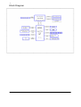
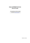
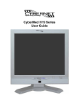
Block Diagram
8
Chapter 1
Chapter 2
System Utilities
CMOS Setup Utility
CMOS setup is a hard ware configuration program built into the system ROM, called the complementary
metal- oxide semiconductor (CMOS) Setup Utility. Since most systems are already properly configured and
optimized, there is no need to run this utility. You will need to run this utility under the following condition.
•
When changing the system configuration settings
•
When redefining the communication ports to prevent any conflicts
•
When modifying the power management configuration
•
When changing the password or making other changes to the security setup
•
When a configuration error is detected by the system and you are prompted ("Run Setup"
message) to make changes to the CMOS setup
NOTE: If you repeatedly receive Run Setup messages, the battery may be bad. In this case, the system
cannot retain configuration values in CMOS. Ask a qualified technician for assistance.
CMOS setup loads the configuration values in a battery-backed nonvolatile memory called CMOS RAM.
This memory area is not part of the system RAM which allows configuration data to be retained when
power is turned off.
Before you run the CMOS Setup Utility, make sure that you have saved all open files. The system reboots
immediately after you close the Setup.
NOTE: CMOS Setup Utility will be simply referred to as “BIOS”, "Setup", or "Setup utility" In this guide.
The screen shots used in this guide display default system values. These values may not be the same
those found in your system.
Chapter2
9
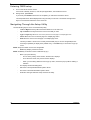
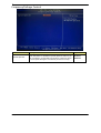
Entering CMOS setup
1.
Turn on the server and the monitor.
If the server is already turned on, close all open applications, then restart the server.
2.
During POST, press Delete.
If you fail to press Delete before POST is completed, you will need to restart the server.
The Setup Main menu will be displayed showing the Setup’s menu bar. Use the left and right arrow
keys to move between selections on the menu bar.
Navigating Through the Setup Utility
Use the following keys to move around the Setup utility.
•
Left and Right arrow keys–Move between selections on the menu bar.
•
Up and Down arrow keys–Move the cursor to the field you want.
•
PgUp and PgDn keys–Move the cursor to the previous and next page of a multiple page menu.
•
Home–Move the cursor to the first page of a multiple page menu.
•
End–Move the cursor to the last page of a multiple page menu.
•
+and-keys–Select a value for the currently selected field (only if it is user-configurable).Press
these keys repeatedly to display each possible entry, or the Enter key to choose from a pop-up
menu.
NOTE: Grayed-out fields are not user-configurable.
•
Enter key–Display a submenu screen.
NOTE: Availability of submenu screen is indicated by a(>).
•
Esc–If you press this key:
•
On one of the primary menu screens, the Exit menu displays.
•
On a submenu screen, the previous screen displays.
•
When you are making selections from a pop-up menu, closes the pop-up without making a
selection.
10
•
F1–Display the General Help panel.
•
F6–Press to load optimized default system values.
•
F7–Press to load fail-safe default system values.
•
F10–Save changes made the Setup and close the utility.
Chapter2
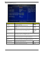
Setup Utility Menus
The Setup Main menu includes the following main setup categories.
Description
Parameter
Product Information
This page shows the relevant information of the main board
Standard CMOS Features
This setup page includes all the items in standard compatible BIOS
Advanced BIOS Features
This setup page includes all the items of Award special enhanced features
Advanced Chipset
Features
Integrated Peripherals
This setup page includes all advanced chipset features
This setup page includes all onboard peripherals
Power Management Setup
This setup page includes all the items of Green function features
PC Health Status
This setup page is the System auto detect Temperature, voltage, and fan
speed
Frequency/Voltage Control
This setup page is the System Frequency setup
BIOS Security Features
Change, set or disable password. It allows you to limit access to the
System
Load Default Setting
Load Default Setting indicates the value of the system in best performance
configurationparameters which the system would be
Save & Exit Setup
Save CMOS value settings to CMOS and exit setup
Exit Without Saving
Abandon all CMOS value changes and exit setup
In the descriptive table following each of the menu screen shots, settings in boldface are the default and
suggested settings
Chapter2
11
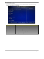
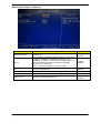
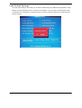
Product Information
The Product Information menu displays basic information about the system. These entries are for your
reference only and are not user-configurable.
12
Parameter
Description
Processor Type
Type of CPU installed on the system.
Processor Speed
Speed of the CPU installed on the system.
System Memory
Total size of system memory installed on the system.
Product Name
Product name of the system.
System Serial Number
Serial number of the system.
System BIOS Version
Version number of the BIOS setup utility.
BIOS Release Date
Date when the BIOS setup utility was released
Asset Tag Number
Asset tag number of this system.
Chapter2
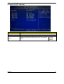
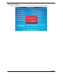
Standard CMOS Features
.
Parameter
Description
System Date
Set the date following the weekday-month-day-year format.
System Time
Set the system time following the hour-minute-second format.
Halt On
Determines whether the system will stop for an error during the
POST.
Chapter2
All, But
Keyboard
No Errors
All Errors
13
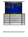
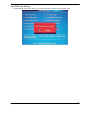
Advanced BIOS Feature
.
Parameter
Quick Boot
Quiet Boot
14
Description
Allows you to decrease the time it takes to boot the
computer by shortening
or skipping certain standard booting process.
When enabled, the BIOS splash screen displays during
startup.
When disabled, the diagnostic screen displays during
startup.
Option
Enabled
Disabled
Enabled
Disabled
Hard Disk
CD^DVD
Removable
Device
LAN
1st/2nd/3rd/4th Boot
Device
Specifies the boot order from the available devices.
Hard Disk Drive Priority
Press Enter to access the Hard Disk Drive Priority submenu and specify the boot
device priority sequence from available hard drives.
Optical Disk Drives
Priority
Press Enter to access the Optical Disk Drive Priority submenu and specify the
boot device priority sequence from available CD/DVD drives.
Removable Device
Priority
Press Enter to access the Removable Device Priority submenu and specify the
boot device priority sequence from available removable drives.
Bootup Num-Lock
Selects power on state for Num Lock.
On
Off
USB Beep Message
Enables or disables BIOS to display error beeps or
messages during USB device enumeration.
Disabled
Enabled
Chapter2
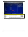
Advanced Chipset Features
Parameter
AMD Cool’n’ Quiet
Description
When enabled, this feature allows the OS to reduce power
consumption.
When disabled, the system operates at maximum CPU speed.
Option
Enabled
Disabled
AMD-V
Enables or disables the Virtualization Technology (VT)
availability. If enabled, a virtual machine manager (VMM) can
utilize the additional hardware virtualization capabilities
provided by this technology.
Note: A full reset is required to change the setting.
Enabled
Disabled
ASF
Enables or disables ASF
Enabled
Disabled
Primary Video
Select a Video memory size
Auto
UMA Frame buffer Size
Select a Frame buffe size
Auto
Enables or disables Surrande view
Enabled
Disabled
Surround view
Chapter2
15
Integrated Peripherals
16
Parameter
Description
Option
Onboard SATA Controller
Enables or disables the onboard SATA controller.
Enabled
Disabled
Onboard SATA Mode
Select an operating mode for the onboard SATA.
RAID
Native IDE
Onboard USB Controller
Enables or disables the onboard USB controller.
Enabled
Disabled
Legacy USB Support
Enables or disables support for legacy USB devices.
Enabled
Disabled
USB Storage Emulation
Enables or disables support for legacy USB devices.
Enabled
Disabled
Onboard Graphics
Controller
Enables or disables the onboard USB controller.
Enabled
Disabled
Onboard Graphics Mode
select a mode of the onboard graphics
UMA
Onboard Audio Controller
Enables or disables the onboard audio controller.
Enabled
Disabled
Onboard LAN Controller
Enables or disables the onboard LAN controller.
Enabled
Disabled
Onboard LAN Option ROM
Enables or disables the load of embedded option ROM for
onboard network controller.
Enabled
Disabled
Onboard Floppy Controller
Enables or disables the onboard Floppy controller.
Enabled
Disabled
Serial Port1 Address
select a port base on address
3F8/IRQ4
Serial Port1 Mode
select the mode
Normal
Serial Port2
select a port base on address
2F8/IRQ3
Serial Port2 Mode
select the mode
Normal
Parallel Port
Address
select a port base on address
378
Parallel Port
Mode
select the mode
Normal
Address
Chapter2
Power Management Setup
Parameter
Description
Option
ACPI Suspend Mode
Select an ACPI state.
S3 (STR)
S1 (POS)
Deep power off mode
Select the Deep power off Mode
Enabled
Disabled
Power On by RTC Alarm
Enables or Disables to wake up the system by RTC Alarm
Function
Enabled
Disabled
Power On by PCIE Devices
Enables or disables to wake up the system from a power
saving mode through an event on PCI Express device.
Enabled
Disabled
Power On by PCI Devices
Enables or disables to wake up the system from a power
saving mode through an event on PCI device.
Enabled
Disabled
Power On by Modem Ring
Enables or disables to wake up the system from a power
saving mode through Modem Ring.
Enabled
Disabled
Wake Up by PS/2
KB/Mouse
Enables or disables to wake up the system from a power
saving mode using a PS2 keyboard or mouse.
Enabled
Disabled
Wake Up by USB KB/Mouse
If enabled, press any key or click the mouse will wake system
from S1/S3 state.
Enabled
Disabled
Restore On AC Power Loss
Enables or disables the system to reboot after a power failure
or
interrupt occurs.
Power Off
Power On
Last State
Chapter2
17
PC Health Status
Parameter
18
Description
Option
system Shutdown
Temperature
Select the system Shutdown Temperature
Enabled
Disabled
CPU Shutdown
Temperature
Select the system Shutdown Temperature
Enabled
Disabled
Smart FAN
Enables or disables the smart system fan control function.
Enabled
Disabled
Chapter2
Frequency/Voltage Control
.
Parameter
Description
Option
Spread Spectrum
Enables or disables the reduction of the mainboard’s EMI.
Note: Remember to disable the Spread Spectrum feature if you
are overclocking. A slight jitter can introduce a temporary boost
in clock speed causing the overclocked processor to lock up.
Enabled
Disabled
Chapter2
19
BIOS Security Features
Parameter
Description
Supervisor Password
Indicates the status of the supervisor password.
User Password
Indicates the status of the user password.
Change Supervisor
Password
Supervisor password prevents unauthorized access to the BIOS
Setup Utility.
Press Enter to change the Supervisor password.
.
Setting a supervisor password
1.
Use the up/down arrow keys to select Change Supervisor Password menu then press Enter.
A password box will appear.
2.
Type a password then press Enter.
The password may consist up to six alphanumeric characters (A-Z,a-z,0-9)
3.
Retype the password to verify the first entry then press Enter again.
4.
Press F10.
5.
Select Yes to save the new password and close the Setup Utility.
Changing the supervisor password
1.
Use the up/down arrow keys to select Change Supervisor Password menu then press Enter.
2.
Type the original password then press Enter.
3.
Type a new password then press Enter.
4.
Retype the password to verify the first entry then press Enter again.
5.
Press F10.
6.
Select Yes to save the new password and close the Setup Utility.
Removing a supervisor password
20
1.
Use the up/down arrow keys to select Change Supervisor Password menu then press Enter.
2.
Enter the current password then press Enter.
3.
Press Enter twice without entering anything in the password fields.
Chapter2
Load Default Settings
The Load Default Settings menu allows you to load the default settings for all BIOS setup parameters. Setup
defaults are quite demanding in terms of resources consumption. If you are using low-speed memory chips
or other kinds of low-performance components and you choose to load these settings, the system might not
function properly.
Chapter2
21
Save & Exit Setup
The Save & Exit Setup menu allows you to save changes made and close the Setup Utility.
22
Chapter2
Exit Without Saving
The Exit Without Saving menu allows you to discard changes made and close the Setup Utility.
Chapter2
23
Chapter 3
System Disassembly and Assembly
This chapter contains step-by-step procedures on how to disassemble and assembly the desktop computer
for maintenance and troubleshooting.
Disassembly Requirements
To disassemble the computer, you need the following tools:
•
Wrist grounding strap and conductive mat for preventing electrostatic discharge
•
Flat-blade screwdriver
•
Philips screwdriver
•
Hex screwdriver
•
Plastic flat-blade screwdriver
•
Plastic tweezers
NOTE: The screws for the different components vary in size. During the disassembly process, group the
screws with the corresponding components to avoid mismatch when putting back the components.
Chapter3
24
Pre-disassembly Procedure
Before proceeding with the disassembly procedure, perform the steps listed below:
25
1.
Turn off the system and all the peripherals connected to it.
2.
Unplug the power cord from the power outlets.
3.
Unplug the power cord from the system.
4.
Unplug all peripheral cables from the system.
5.
Place the system unit on a flat, stable surface.
Chapter3
Removing the Side Panel
a.
Loose screw x 2.(5±0.5 Kgf.cm)
b.
Remove left side panel and take out it.
Chapter3
26
Removing the Front Bezel
27
a.
Release the front bezel retention tabs from the chassis interior.
b.
Pull the bezel away from the chassis.
Chapter3
Removing the Top Bezel
Pull the Top Bezel away from the Chassis.
.
a.
a
b.
Release the top bezel retention tabs from the chassis interior.
b
Chapter3
28
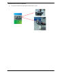
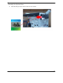
Removing the VGA Card
29
a.
Releasing cover slot.
b.
Remove the screw that secures the card to the chassis.
Chapter3
c.
Gently pull the card to remove it from the main board (PCI-E x16).
Chapter3
30
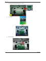
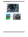
Removing the TV Card
31
a.
Remove the screw that secures the card to the chassis.
b.
Gently pull the card to remove it from the main board (PCI-E x1).
Chapter3
Removing the System Fan
a.
Removing the four screws that secures the system fan to the chassis.
b.
Take out the system fan from the chassis.
Chapter3
32
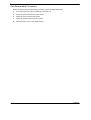
Removing the Power Supply
33
a.
Disconnect the 4-pin and 24-pin power supply cables from the main board.
b.
Remove the screw that secures the power supply to the chassis.
Chapter3
c.
Lift the power supply module out of the chassis.
Chapter3
34
Removing the Optical Drive
a.
35
Remove the two screws that secure the main board to the chassis..
Chapter3
Removing the Hard Disk Drive
a.
Release the two screws that secure the HDD bracket to the chassis.
b.
Remove the two screws that secure HDD to the HDD bracket.
Chapter3
36
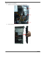
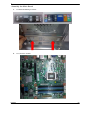
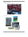
Removing the Main board
a.
Disconnect the cable from the main board .
Card Reader
Power S/W
b.
37
Front USB
SPDIF/ USB
TOP USB
Audio
Remove the seven screws that secure the main board to the chassis.
Chapter3
c.
Punching in IO Shield then you can remove it.
.
Chapter 3
38
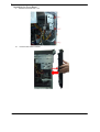
Removing the Light Board Module and LED Cable
39
a.
Release LED cable from the chassis interior.
b.
Remove the two screws that secure the light board to the chassis.
Chapter 3
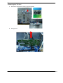
Removing the Card Reader and LED Cable Assembly
a.
Remove the two screws that secure the bracket to the chassis.
b.
Remove the card reader away from chassis.
Chapter3
40
Removing the Front I/O Module
a.
41
Remove the screws that secure the bracket to the chassis.
Chapter3
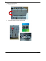
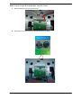
Removing the Top USB Module
a.
Remove the two screws that secure the bracket to the chassis.
b.
c.
Remove the two screws that secure the USB board to the bracket.
Remove the USB board then lift the USB board out of bracket.
c
Chapter3
b
42
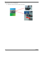
d.
Disconnet the USB cable away from USB board.
43
Chapter3
Disassembly Procedure
Assembly the Top USB Module
a.
Connet the USB cable to USB board.
b.
c.
Assembly the USB board with bracket.
Assembly the two screws that secure the USB board to the bracket.
b
Chapter3
c
44
d.
45
Put top USB module into the top side of chassis and fix two screws.
Chapter3
Assembly the Front I/O Module
a.
Chapter3
Put front I/O module into the top side of chassis and fix 1 screw.
46
Assembly the Card Reader and LED Cable Assembly
a.
Put card reader module into the front side of chassis and A1 hook to A2 holes / B1 hook to B2
holes.
b.
Fix 2 screws to add the bracket to the chassis
.
47
Chapter3
Assembly the Light Board Module and LED Cable
a.
b.
Put Light board to Light board bracket along the arrow.
.
Fix 2 screws.
Chapter3
48
c.
Put Light board module into the top side of chassis
c
d.
e.
49
Fix 2 screws.
Add the LED cable
Chapter3
Assembly the Main Board
a.
Put Real I/O shielding to chassis.
b.
Fix 8 screws in chassis.
Chapter3
50
Assembly the Hard Disk Drive
a.
Put HDD in the cage along the arrow.
b.
Fix screws x4 (5±0.5 Kgf.cm) on the cage.
c. Push HDD bracket along the arrow and fix 1 screw.
51
Chapter3
Assembly the Optical Drive
a.
Push ODD along the arrow and fix screws x2 on the chassis.
Chapter3
52
Assembly the Power Supply
53
a.
Disconnect the 4-pin and 24-pin power supply cables from the main board.
b.
Remove the screw that secures the power supply to the chassis.
c.
Connect 24 pin main power and 4 pin power cable to MB.
Chapter3
Assembly the system Fan
a. Put System fan into chassis
b.
Fix 4 screws.
Chapter3
54
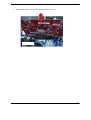
Assembly the TV Card
a.
55
Remove cover slot lock and PCI slot 1、3.
b.
Plug-in TV tuner card to PCI-E x1
c.
Fix 1 screw. .
Chapter3
Assembly the VGA Card
a.
Plug-in VGA card to PCI-E x16.
b.
Fix 1 screw.
Chapter3
56
Assembly the Top Bezel
a.
b.
57
Put back the top bezel along the arrow .
Push back the top bezel to chassis.
Chapter3
Assembly the Front Bezel
a.
b.
Chapter 3
Put back front bezel hook 1,2,3.
Push the front bezel to chassis.
58
Assembly the Side Panel
a.
b.
59
Recover left side panel.
Fix 2 screws.
Chapter 3
Chapter 4
System Trouble shooting
This chapter provides instructions on how to trouble shoot system hardware problems.
Hardware Diagnostic Procedure
IMPORTANT: The diagnostic tests described in this chapter are only intended to test Acer products. Non-Acer
products, prototype cards, or modified options can give false errors and invalid system
responses.
1.
Obtain the failing symptoms in as much detail as possible.
2.
Verify the symptoms by attempting to recreate the failure by running the diagnostic tests or repeating
the same operation.
3.
Refer to “Power System check” and “Beep Codes” to determine which corrective action to perform.
Chapter4
60
System Check Procedures
Power System Check
If the system will power on, skip this section. Refer to System External Inspection.
If the system will not power on, do the following:
•
Check if the power cable is properly connected to the system and AC source.
•
Check if the voltage selector switchis set to the correct voltage setting.
System External Inspection
1.
Inspect the LED indicators on the front panel, which can indicate the malfunction.
2.
Make sure that air flow is not blocked.
3.
Make sure nothing in the system is making contact that could short out power.
4.
If the problem is not evident, continue with System Internal Inspection.
System Internal Inspection
1.
Turn off the system and all the peripherals connected to it.
2.
Unplug the power cord from the power outlets.
3.
Unplug the power cord from the system.
4.
Unplug all peripheral cables from the system.
5.
Place the system unit on a flat, stable surface.
6.
Remove the system covers. For instructions on removing system covers, refer to “System Disassembly”.
7.
Verify that components are properly seated.
8.
Verify that all cable connectors inside the system are firmly and correctly attached to their appropriate
connectors.
9.
Verify that all components are Acer-qualified and supported.
10. Replace the system covers.
11. Power on the system.
12. If the problem with the system is not evident, you can try viewing the POST messages and BIOS event
logs during the system startup.
61
Chapter4
Beep Codes
Beep codes are used by the BIOS to indicate a serious or fatal error to the end user. Beep codes are used
when an error occurs before the system video has been initialized. Beep codes will be generated by the
system board speaker, commonly referred to as the PC speaker.
AMIBIOS displays the checkpoints in the bottom right corner of the screen during POST. This display method
is limited, since it only displays checkpoints that occur after the video card has been activated.
Not all computers using AMIBIOS enable this feature. In most cases, a checkpoint card is the best tool for
viewing AMIBIOS checkpoints.
System ready
Symptom:
One short beep.
Description:
System is OK.
Memory not installed or memory error
Symptom:
Continuous one long beep.
Description:
Something is wrong with the memory installed.
Note that there could also be something wrong with
just accessing the memory (ie the motherboard has a
problem).
VGA not installed or VGA error
Symptom:
One long beep, then two short
beeps and repeat.
Description:
The motherboard is not able to access the video
card for some reasons. Either the video card is not
working, its memory is not accessible, or its BIOS
may be corrupt. This error code could also mean
something is wrong with the motherboard.
BIOS damaged
Symptom:
One long beep, then one short
beep.
Description:
BIOS damaged. Processor jump to BootBlock to
execute the default procedure.
CMOS damaged
Symptom:
Two short beeps.
Description:
CMOS checksum error.
.
Chapter4
62
Checkpoints
A checkpoint is either a byte or word value output to I/O port 80h. The BIOS outputs checkpoints throughout
bootblock and Power-On Self Test (POST) to indicate the task the system is currently executing. Checkpoint
sare very useful in aiding software developers or technicians in debugging problems that occur during the preboot process.
Viewing BIOS checkpoints
Viewing all checkpoints generated by the BIOS requires acheckpoint card, also referred to as a POST card
or POST diagnostic card. These are ISA or PCI add-in cards that show the value of I/O port 80h on a LED
display. Checkpoints may appear on the bottom right corner of the screen during POST. This display method
islimited, since it only displays checkpoints that occur after the video card has been activated.
Bootblock Initialization Code Checkpoints
The Bootblock initialization code sets up the chipset, memory, and other components before system memory
is available. The following table describes the type of checkpoints that may occur during the bootblock
initialization portion of the BIOS.
NOTE: Please note that checkpoints may differ between different platforms based on system configuration.
Checkpoints may change due to vendor requirements, system chipset or option ROMs from add-in
PCI devices.
Checkpoint
Before D0
D0
D1
D2
D3
D4
If boot block debugger is enabled, CPU cache-as-RAM functionality is enabled at this
point. Stack will be enabled from this point.
Early Boot Strap Processor (BSP) initialization like microcode update, frequency and
other CPU critical initialization. Early chipset initialization is done.
Early super I/O initialization is done including RTC and keyboard controller. Serial port
is
enabled at this point if needed for debugging. NMI is disabled. Perform keyboard
controller BAT test. Save power-on CPUID value in scratch CMOS. Go to flat mode
with 4GB limit and GA20 enabled.
Verify the boot block checksum. System will hang here if checksum is bad.
Disable CACHE before memory detection. Execute full memory sizing module. If
memory sizing module not executed, start memory refresh and do memory sizing in
Boot block code. Do additional chipset initialization. Re-enable CACHE. Verify
that flat mode is enabled.
Test base 512KB memory. Adjust policies and cache first 8MB. Set stack.
D7
Bootblock code is copied from ROM to lower system memory and control is given to it.
BIOS now executes out of RAM. Copies compressed boot block code to memory in
right segments. Copies BIOS from ROM to RAM for faster access. Performs main
BIOS checksum and updates recovery status accordingly.
Both key sequence and OEM specific method is checked to determine if BIOSrecovery
is forced. Main BIOS checksum is tested. If BIOS recovery is necessary,control
flows to checkpoint E0. See Bootblock Recovery Code Checkpoints sectionfor more
information.
Restore CPUID value back into register. The Bootblock-Runtime interface module is
moved to system memory and control is given to it. Determine whether to execute
serial flash.
D8
The Runtime module is uncompressed into memory.
memory.
D9
Store the Uncompressed pointer for future use in PMM. Copying Main BIOS into
memory. Leaves all RAM below 1MB Read-Write including E000 and F000 shadow
areas but closing SMRAM.
D5
D6
63
Description
CPUID information is stored in
Chapter4
Checkpoint
DA
DC
E1-E8 ECEE
Chapter4
Description
Restore CPUID value back into register. Give control to BIOS POST
(ExecutePOSTKernel).See POST Code Checkpoints section of document for more
information.
System is waking from ACPI S3 state.
OEM memory detection/configuration error. This range is reserved for chipset vendors
& system manufacturers. The error associated with this value may be different from
one platform to the next.
64
Bootblock Recovery Code Checkpoints
The Bootblock recovery code gets control when the BIOS determines that a BIOS recovery needs to occur
because the user has forced the update or the BIOS checksum is corrupt. The following table describes the
type of checkpoints that may occur during the Bootblock recovery portion of the BIOS.
NOTE: Checkpoints may differ between different platforms based on system configuration. Checkpoints may
change due to vendor requirements, system chipset or option ROMs from add-in PCI devices.
Checkpoint
E0
E9
EA
EB
EF
F0
F1
F2
F3
F5
FA
FB
F4
FC
FD
FF
65
Description
Initialize the floppy controller in the super I/O. Some interrupt vectors are initialized.
DMA controller is initialized. 8259 interrupt controller is initialized. L1 cache is
enabled.
Set up floppy controller and data. Attempt to read from floppy.
Enable ATAPI hardware. Attempt to read from ARMD and ATAPI CDROM.
Disable ATAPI hardware. Jump back to checkpoint E9.
Read error occurred on media. Jump back to checkpoint EB.
Search for pre-defined recovery file name in root directory.
Recovery file not found.
Start reading FAT table and analyze FAT to find the clusters occupied by the recovery
file.
Start reading the recovery file cluster by cluster.
Disable L1 cache.
Check the validity of the recovery file configuration to the current configuration of the
flash part.
Make flash write enabled through chipset and OEM specific method. Detect proper
flash part. Verify that the found flash part size equals the recovery file size.
The recovery file size does not equal the found flash part size.
Erase the flash part
Program the flash part.
The flash has been updated successfully. Make flash write disabled. Disable ATAPI
hardware. Restore CPUID value back into register. Give control to F000 ROM at
F000:FFF0h.
Chapter4
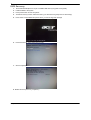
BIOS Recovery
1.
Put the BIOS.ROM (like P01-A0) to a bootable USB memory key (Disk on Key,DOK).
2. Install the DOK to the system
3. Press power button to boot the system.
4. The BIOS recovery function will be executed. (you will head a long beep and one short beep)
5. Press <Del> to enter BIOS setup menu when you see the logo and message
6. Press Proceed with flash update start recovery.
7. Wait it compeled
8. ENTER and exit. (Recovery completed.)
Chapter4
66
Chapter 5
Jumper Information
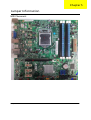
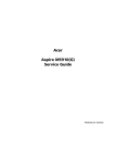
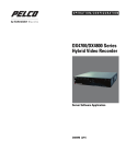
M/B Placement
Chapter5
67
68
No.
Label
1
CPU socket
3
ATXPOWER
5
Description
AM3 socket for CPU
No.
Label
Description
2
DIMM
DDRIII DIMM slot
M/B Main Power
connector
4
ATX CPU
CPU Fan
CPU Fan header
6
SATA1~6
7
F_PANEL
Front panel switch/LED
8
F_USB1
9
F_USB2~4
Front panel USB headers
10
SPDIF_OUT
SPDIF out header
11
F_AUDIO
Front panel audio header
12
BATTERY
RTC BATTERY
13
PCIE X16
PCIEx16 slot
14
PCIE X1
PCIEx1 slot
15
PCIE X1
PCIEx1 slot
16
PCIE X1
PCIEx1 slot
CPU Power
connector
SATA connectors
Card reader USB
header
Chapter5
Jumper Setting
The section explains how to set jumper for correct configuration of the main board.
Setting Jumper
Use the mother board jumpers to set system configuration options. Jumpers with more Than one pin are numbered.
When setting the jumpers, ensure that the jumper caps are Placed on the correct pins.
The illustrations show a 2-pin jumper.When the jumper cap is placed on bothpins,the jumper is SHORT.If you re-move
the jumper cap,or place the jumpercap on just one pin,the jumper is OPEN.
This illustration shows a 3-pin jumper.Pins 1 and 2 are SHORT.
Chapter5
69
The following illustration shows the location of the motherboard jumpers. Pin 1 is labeled.
Jumper
Type
Description
CLR_CMOS1
3-pin
CLEAR CMOS
ME_CLR1
3-pin
MEDISABLE
Setting(default)
1-2:NORMAL
2-3:CLEAR
Before clearing the
CMOS,make sure toturn the
system off.
CLR_CMOS1
1-2:NORMAL
2-3:MEDISABLE
ME_CLR1
70
Chapter5
Chapter 6
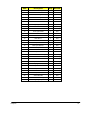
FRU (Field Replaceable Unit) List
This chapter offers the FRU (Field Replaceable Unit) list in global configuration of the IXTREMEM5860
desktop computer. Refer to this chapter whenever ordering the parts to repair or for RMA (Return
Merchandise Authorization).
NOTES:
•
When ordering FRU parts, check the most up-to-date information available on your regional web
or channel. For whatever reasons a part number is changed, it will NOT be noted on the printed
Service Guide. For Acer authorized service providers, your Acer office may have a different
part number code from those given in the FRU list of this printed Service Guide. You MUST use
the local FRU list provided by your regional Acer office to order FRU parts for service.
•
To scrap or to return the defectives, follow the local government ordinance or regulations on how
to dispose it properly, or follow the rules set by your regional Acer office on how to return it.
•
Chapter6
This document will be updated as more information about the FRU list becomes available.
71
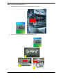
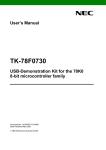
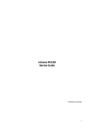
DX4380(G) Exploded Diagram
NOTE: This section will be updated when more information becomes available.
72
Chapter6
Chapter6
Item
Description
Q'ty
Remark
1
Side Cover Right
1
Part
2
MB Plate
1
Part
3
HDD Cage
1
Part
4
ODD Cage
1
Part
5
Main Chassis
1
Part
6
FDD EMI Cover
1
Part
7
Logo Light Base
1
Part
8
Front Bezel Trim
1
Assembly
9
Front Bezel Frame
1
Assembly
10
Front Light Guide
1
Part
11
Front Cover
1
Part
12
ODD Door 2
1
Part
13
ODD Door 1
2
Part
14
ODD Door Shift
1
Part
15
ODD Eject Button 2
1
Part
16
ODD Eject Button 1
2
Part
17
ODD Eject Rod
1
Part
18
Front IO Bracket
2
Part
19
Top Link Bar
1
Part
20
LED & Switch Holder Right
1
Assembly
21
Power PCB Bracket
1
Assembly
22
LED & Switch Holder Left
1
Assembly
23
Top Bezel Frame
1
Assembly
24
Top Light Guide
1
Part
25
Top Bezel Trim
1
Part
26
Top Bezel
1
Assembly
27
Power Button
1
Assembly
28
Top Cover
1
Part
29
SPDIF Bracket
1
Part
30
Rear IO Shielding
1
Part
31
Logo Light Pipe
1
Part
73
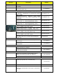
ixtremeM5860 FRU List
Category
Description
Number
Main board
SKU1: Baseline
MB.GBL01.001
Chassis
Chassis MicroATX HM100C with front+top USB port
for P5_30L (PB) Bezel w/o 3.5" HDD carrier
HS.13100.162
Chassis MicroATX HM100D with front+top USB port
for P5_30L (PB) Bezel w/o 3.5" HDD carrier
HS.13100.163
Bezel
ECS (AVC) PB Bezel PM350 USB 2+2 port bezel for
HM100A, w/o 3.5" HDD carrier, w/i PhotoFrame &
Backup button
CS (AVC) PB Bezel PM351 USB 2+2 port bezel for
HM100B, w/i one 3.5" HDD carrier, w/i PhotoFrame
& Backup button
PZ.11900.215
PZ.11900.216
CPU Cooler
Intel LGA1156
HI.10800.058
Intel LGA1156
HI.10800.048
SYSTEM FAN KDE 1209/GP 92*92*25 (ROHS)
HI.S150F.002
System Fan
PSU
DPS-250AB-63A
PS-5251-7A2
DPS-250AB-66A
DPS-250AB-63A
PS-5251-7A2
ATX250PA(1)(A01004)
PY.25009.019
FSP450-60EP(A01003)
PY.50008.005
ATX-250PA(1)(A01004)
CPU
Chapter6
Ci7-2600
KC.26001.CI7
Ci5-2500
KC.25001.CI5
Ci5-2400
Ci5-2300
KC.24001.CI5
Ci3-2100
KC.21001.CI3
KC.23001.CI5
74
Category
Description
Number
Memory
M378B2873FHS‐CH9 LF 128*8 46nm
M378B5673FH0‐CH9 LF 128*8 46nm
M378B5273DH0‐CH9 4GB
ACR128X64D3U1333C9 LF 128*8 0.07um
ACR256X64D3U1333C9 LF 128*8 0.07um
GU502203EP0201 LF 128*8 0.065um 1GB
GU512303EP0202 LF 128*8 0.065um 2GB
75.073C1.G02 LF 128*8 0.065um 2GB
NT4GC64B8HB0NF‐CG 4GB
Memory APACER UNB‐DIMM DDRIII 1333 1GB
75.073C1.G02 LF 128*8 0.065um
Memory APACER UNB‐DIMM DDRIII 1333 2GB
75.A73C1.G02 LF 128*8 0.065um
Memory A‐DATA UNB‐DIMM DDRIII 1333 1GB
AD63I1A0823EU LF 128*8 0.065um
KN.1GB0B.036
KN.2GB0B.029
KN.4GB0B.014
KN.1GB07.002
KN.2GB07.002
KN.1GB0H.015
KN.2GB0H.009
KN.2GB03.022
KN.4GB03.006
KN.1GB01.031
KN.2GB01.025
KN.1GB0C.010
HDD
HDD HGST 3.5" 7200rpm 500GB HDS721050CLA362
(Jupiter) SATA II 16MB LF F/W:3EA
HDD HGST 3.5" 7200rpm 640GB HDS721064CLA332
(Jupiter) SATA II 32MB LF F/W:3EA
HDD HGST 3.5" 7200rpm 1000GB HDS721010CLA332
(Jupiter) SATA II 32MB LF F/W:3EA
HDD
SEAGATE
3.5"
7200rpm
500GB
ST3500418AS(Pharaoh PB) SATA II 16MB LF F/W:CC44
HDD
SEAGATE
3.5"
7200rpm
1000GB
ST31000528AS(Pharaoh BP) SATA II 32MB LF
F/W:CC44
HDD
SEAGATE
3.5"
7200rpm
1500GB
ST31500341AS(Brinks) SATA II 32MB LF F/W:CC4H
HDD WD 3.5" 7200rpm 500GB WD5000AAKS‐22V1A0
SATA II 16MB LF F/W:05.01D05
HDD WD 3.5" 7200rpm 640GB WD6400AAKS‐22A7B2
XL320M 640G SATA II 16MB LF F/W:01.03B01
HDD WD 3.5" 5400rpm 1500GB WD15EADS-22P8B0
( GP500 ) SATA 32MB LF F/W:01.00A01
HDD WD 3.5" 5400rpm 2000GB WD20EADS-22R6B0
(GP500) SATA II 32MB LF F/W:01.00A01
KH.50007.012
KH.64007.002
KH.01K07.003
KH.50001.019
KH.01K01.013
KH.15K01.002
KH.50008.014
KH.64008.003
KH.15K08.001
KH.02K08.001
SuperMulti
ODD HLDS Super-Multi DRIVE HH DL 16X GH60N
LF+HF Black Bezel SATA HF+Win7
KU.0160D.052
ODD PLDS Super-Multi DRIVE HH DL 16X DH-16ABSH
LF Black Bezel (HF+Win7) SATA
KU.0160F.011
ODD HLDS BD COMBO HH 6X CH20N Black Bezel
SATA HF + Win7
KO.0060D.005
ODD PLDS BD COMBO HH 6X DH-6E2S Black Bezel
SATA w/ Win 7
KO.0060F.002
BD Combo
Category
Description
Number
BD Writer
ODD HLDS BD RW HH 6X BH30N Black Bezel SATA
HF +Win7
KU.0060D.004
ODD PLDS BD RW HH DL 6X DH-6B2SH LF+HF Black
Bezel SATA (Win7+HF)
KU.0060F.001
VGA
288-7E160-A00AC HD6750 1GB GDDR 5
(128BITS) SAMSUNG DVI HDMI DP W/ATX
BKT ROHS
288-5E142-001AC HD6570 1GB DDR3
128BITS DVI-I (SL) HDMI SAMSUNG ATX
BRACKET
288-5E153-000AC HD6450 1GB SDDR3
64bits DVI-I + HDMI SAMSUNG (ATX)
288-1E180-000AC HD6450 512MB SDDR3
64bits DVI-I + HDMI SAMSUNG (ATX)
288-2N162-101AC GT420 2GB 128bit
DVI-I+HDMI+VGA ATX Hynix
288-2N162-001AC GT420 2GB SDDR3
128bit Samsung DVI+HDMI+VGA ATX
288-1N162-001AC GT420 1GB 128bit
DVI-I+HDMI+VGA ATX Samsung
288-1N162-101AC GT420 1GB 128bit
DVI-I+HDMI+VGA ATX Hynix
288-1E153-200AC AMD HD5450 512MB 64bits sDDR3
DVI+HDMI+VGA ATX 4 LAYER COST DOWN (New
Hynix -1.2)
VG.APC67.501
VG.APC65.701
VG.APC64.520
VG.APC64.501
VG.PCPT4.251
VG.PCPT4.252
VG.PCPT4.201
VG.PCPT4.202
VG.APC54.524
TV-Tuner
Avermedia H753-A TV Tuner Card PCIe Hybrid ATSC,
S/W Encoder
TU.10500.072
Avermedia H753-D TV Tuner Card PCIe Hybrid DVB-T,
S/W Encoder
TU.10500.074
Philips Remote Controller RC2604307/01BG for
EMEA ;pair with RV.11000.007
RT.11300.021
Philips Remote Controller RC2604302/01B MSFT code
US;pair with OVU430008
RT.11300.022
Philips OVU710018 Win7 receiver Philips code for
EMEA, H57 fixed FW, pair with RT.11300.021
RV.11000.025
Philips Win7 OVU430008 with IR blaster
RV.11000.023
Remote
Receiver
Modem
D-1156E#/A10A, Modem PCI-Ex1 card, LSI Universal
Modem (PCI-E) 56K V.92 - Concorde (C40)
FX.10100.002
WLAN
WN7601R, Ralink RT3090, 802.11b/g/n 1x1 WLAN PCIE x1 card
NI.10200.037
Category
Description
Number
Speaker
Neosonica mini speaker USB black ;meet Win7
SP.10600.032
Keyboard LITE-ON SK-9020 USB 104KS Black US
KB.USB0B.283
Keyboard LITE-ON SK-9020 USB 105KS Black UK
KB.USB0B.284
USB keyboard
Keyboard LITE-ON SK-9020 USB 105KS Black Spanish
Latin
Keyboard LITE-ON SK-9020 USB 105KS Black
English/Canadian French
Keyboard LITE-ON SK-9020 USB 104KS Black
Traditional Chinese
KB.USB0B.285
KB.USB0B.286
KB.USB0B.287
Keyboard LITE-ON SK-9020 USB 104KS Black Thailand
KB.USB0B.373
Keyboard LITE-ON SK-9020 USB 109KS Black
Japanese
KB.USB0B.374
Keyboard LITE-ON SK-9020 USB 109KS Black Brazilian
Portuguese leverage the JA 109 key top cover
KB.USB0B.375
USB/P5
MS.11200.081
USB/P5
MS.11200.083
Keyboard LITE-ON SK-9061 RF2.4 104KS Black US
KB.RF40B.083
USB Mouse
Wireless KB
Keyboard LITE-ON SK9061 RF2.4 104KS Black Traditional Chinese
Keyboard LITE-ON SK9061 RF2.4 104KS Black Thailand
Keyboard LITE-ON SK9061 RF2.4 105KS Black Spanish Latin
Keyboard LITE-ON SK9061 RF2.4 107KS Black Brazilian Portuguese
Keyboard LITE-ON SK9061 RF2.4 109KS Black Japanese
KB.RF40B.084
KB.RF40B.085
KB.RF40B.086
KB.RF40B.087
KB.RF40B.088
Keyboard LITE-ON SK-9061 RF2.4 105KS Black UK
KB.RF40B.089
Keyboard LITE-ON SK9061 RF2.4 105KS Black English/Canadian French
KB.RF40B.090
Lite-on P5 optical mouse RF2.4 SM-9661 with
receiver(nano dangle)
MS.11200.084
P5 Cardreader
CR.10400.125
P5 Cardreader
CR.10400.126
Wireless mouse
Card Reader