1
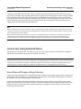
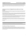
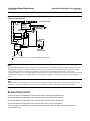
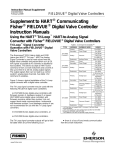
Instruction Manual Supplement
DVC6000/DVC6200 Digital Valve Controllers
D103261X012
February 2011
Supplement to Fisherr FIELDVUEt DVC6000 or
DVC6200 Digital Valve Controller Instruction
Manuals
Implementation of Lock‐in‐Last Strategy
Many applications require a valve assembly to remain in the position it was prior to a specific control system failure
(lock‐in‐last position). Functionality and safety can be designed into valve assemblies with FIELDVUE digital valve
controllers by utilizing an array of accessories. The following paragraphs describe standard solutions for a number of
generic lock‐in‐last applications with DVC6000 or DVC6200 digital valve controllers.
Note
This instruction manual supplement is for use with HARTr communicating FIELDVUE DVC6000 or DVC6200 digital valve
controllers only.
Lock‐in‐Last on Loss of Supply Pressure
Once the supply pressure falls below a minimum value, the digital valve controller can no longer position a valve
assembly; the valve will start to go to the actuator “at rest” position. The locking device senses this change and
activates, preventing the remaining air from venting. The valve is “locked‐in” this new position.
Note
The locked‐in valve position depends on the exhausting speed of the actuator.
Assemblies with Single‐Acting Actuators
A Fisher 164A three‐way switching valve should be used for locking a single‐acting actuator in place on loss of supply
pressure. Figure 1 is a schematic representing proper assembly layout. In normal operation, the digital valve controller
output passes through the switching valve from port A to port B and on to the actuator.
www.Fisher.com
Instruction Manual Supplement
DVC6000/DVC6200 Digital Valve Controllers
February 2011
D103261X012
Figure 1. Lock‐in‐Last on Loss of Supply Pressure for an Assembly with a Single‐Acting Actuator
(Fisher DVC6000 Depicted)
FISHER 164A THREE‐WAY
SWITCHING VALVE
D
A
B
C
DIGITAL
VALVE
AIR
SUPPLY
OUTPUT
SUPPLY
CONTROLLER
FISHER 67CFR
FILTER/REGULATOR
In a fail condition, the pressure at port D is below the switching valve's set point, causing the switching valve to trip.
This closes port B, which locks the pressure in the actuator. Port C is plugged so the digital valve controller output will
not exhaust to the atmosphere.
Assemblies with Double‐Acting Actuators
Similar to the locking strategy used with single‐acting actuators, the locking strategy with double‐acting actuators
also uses a valve for locking supply pressure in the actuator. For assemblies with double‐acting actuators, a Fisher 377L
trip valve is used as the locking device. The 377L trip valve has two output ports for locking pressure on both sides of a
double‐acting actuator. Figure 2 is a schematic representing proper assembly layout.
Figure 2. Lock‐in‐Last on Loss of Supply Pressure for an Assembly with a Double‐Acting Actuator
(Fisher DVC6000 Depicted)
FISHER 377L TRIP VALVE
INPUT
DA
E B
F C
FISHER 64
REGULATOR
DIGITAL
VALVE
CONTROLLER
2
OUTPUT
SUPPLY
OUTPUT
AIR
SUPPLY
Instruction Manual Supplement
D103261X012
DVC6000/DVC6200 Digital Valve Controllers
February 2011
Connection of the digital valve controller output to a double‐acting actuator determines the action of the actuator.
Figure 2 shows the digital valve controller providing lower cylinder pressure through ports D and E, and upper cylinder
pressure through ports A and B. When the supply pressure falls below the set point of the trip valve, the trip valve
closes ports D and A and connects port B to C and port E to F. Because C and F are plugged, the control valve is locked
in place by locking pressure on both sides of the actuator piston. The assembly returns to normal operation once
supply pressure is restored at the trip valve INPUT port.
Note
Double‐acting actuators with a 377L trip valve require a Fisher 64 or 95H regulator. Regulators with smaller flow capacities may
cause the trip valve to cycle (lock and unlock repeatedly) due to air flow demand as the assembly attempts to reset. Use a Fisher
252 or 262C pilot filter to filter supply air.
Both the 164A switching valve and the 377L trip valve have a deadband that must be overcome. The switching valve must be
calibrated to reset upon restoration of adequate supply pressure to the regulator. The 377L trip valve has only one spring
selection. However, for minimal deadband, the lightest appropriate spring should be selected for the 164A switching valve.
Lock‐in‐Last Using Solenoid Valves
Solenoid valves are used with valve assemblies in many ways. Their electrical control can be utilized in combination
with switches and controller logic to perform a number of functions.
Note
Solenoid valves placed between the output of a DVC6000 or DVC6200 digital valve controller and the input to an actuator require
a minimum Cv of 0.49. Greater restrictions can affect the response of the assembly. An example of an appropriate three‐way
solenoid valve for use with the digital valve controller is the ASCO™ 8327 Series solenoid valve from ASCO Valve, Inc.
Assemblies with Single‐Acting Actuators
A three‐way universal solenoid valve can be placed between the digital valve controller output and the actuator input.
Switching the valve assembly from an unlocked state to a locked state is controlled by switching power on and off to
the solenoid valve. Figure 3 depicts proper assembly layout.
Under normal operating conditions the solenoid is energized and supply air flows from the digital valve controller
output to the actuator input. In the fail state, power is removed from the solenoid causing the solenoid valve to close,
locking air pressure in the actuator. Port 1 of the solenoid valve is plugged, preventing actuator air pressure from
exhausting to the atmosphere.
3
Instruction Manual Supplement
DVC6000/DVC6200 Digital Valve Controllers
February 2011
D103261X012
Figure 3. Lock‐in‐Last Strategy for an Assembly with a Single‐Acting Actuator Using a Solenoid Valve
(Fisher DVC6000 Depicted)
SOLENOID VALVE
(ENERGIZED)
2
1
24 VDC
POWER SUPPLY
3
1
FISHER 67CFR
FILTER/REGULATOR
DIGITAL
VALVE
OUTPUT
SUPPLY
AIR
SUPPLY
CONTROLLER
NOTE:
1
A
SOLENOID VALVE WITH A MINIMUM CV OF 0.49, SUCH AS THE
ASCO 8327 SERIES OR EQUIVALENT, IS REQUIRED FOR THIS ASSEMBLY
Assemblies with Double‐Acting Actuators
Assemblies with double‐acting actuators require a 377L trip valve to lock pressures on both sides of the actuator
piston. Figure 4 is a schematic of a double‐acting actuator with lock‐in‐last capability shown in its normal operating
mode. The solenoid valve is placed in series with the signal port of the trip valve. When tripped, the solenoid valve
exhausts the signal pressure to the trip valve to atmosphere. This simulates a loss in supply pressure, causing the trip
valve to lock pressure in the actuator.
Figure 4. Lock‐in‐Last for an Assembly with a Double‐Acting Actuator Using a Solenoid Valve
(Fisher DVC6000 Depicted)
SOLENOID VALVE
(ENERGIZED)
FISHER 377L
TRIP VALVE
D A
E B
F C
1
1
24 VDC
POWER SUPPLY
2
3
FISHER 64
REGULATOR
DIGITAL
VALVE
CONTROLLER
OUTPUT
SUPPLY
OUTPUT
AIR
SUPPLY
FISHER 252
AIR/GAS FILTER
NOTE:
THE
ASCO 8320 SERIES SOLENOID VALVE OR EQUIVALENT IS APPROPRIATE FOR THIS ASSEMBLY.
1
4
Instruction Manual Supplement
DVC6000/DVC6200 Digital Valve Controllers
D103261X012
February 2011
The solenoid valve in this solution does not require a Cv greater than 0.49. Flow capacity of this valve can be much
smaller. An example of a proper solenoid valve for this assembly is the 8320 Series three‐way solenoid valve. As with all
solenoid valves, ensure that the solenoid valve operating pressure differential rating is adequate for the supply
pressure.
Lock‐in‐Last on Loss of Supply Pressure and/or Loss of Loop
Current
Most applications require a valve assembly to be in a lock‐in‐last fail state not only on loss of adequate supply pressure
but also on loss of loop power. Lock‐in‐last on loss of supply pressure is quite straight forward. Lock‐in‐last on loss of
loop power can be more complex.
Most control loops operate on a 4‐20 mA control signal. A solenoid valve, adequately sized for the application, requires
more than 4 mA to energize. Therefore, the control loop cannot be used to energize the solenoid. Instead the solenoid
must be powered by a separate 24 volt power source. Thus an additional device is required to monitor the current to
the digital valve controller and control the power to the solenoid.
A current threshold switch can be used to monitor the 4‐20 mA signal to the digital valve controller. Upon loss of this
signal, or when the signal falls below the threshold, the threshold switch will open an internal relay. This relay, if placed
between a solenoid valve and its power supply, will essentially open and close the solenoid valve. The solenoid valve
can be placed in line with the tubing to the actuator to provide the lock‐in‐last function.
To ensure adequate response time of a locking system to a loss of loop current, a threshold switch with a maximum
deadtime of 0.025 seconds should be used. The locking system will be faster than the response of the positioning
system to the failure.
One switch that meets the maximum deadtime requirements is the Phoenix Contact Dual Setpoint Module, Model
MCR‐2SP/UI.
Note
The MCR‐2SP/UI switch is not provided by Emerson Process Management. Order this switch from Phoenix Contact.
Assemblies with Single‐Acting Actuators
Assemblies with a single‐acting actuator use a 164A three‐way switching valve in conjunction with a solenoid valve.
Figure 5 is a schematic of a single‐acting actuator assembly with lock‐in‐last capability on loss of supply pressure or
loop current. Under normal operating conditions power is supplied to the solenoid valve and adequate supply pressure
is available to the switching valve. Upon loss of supply pressure, the set point of the switching valve is exceeded and
the switching valve trips.
5
Instruction Manual Supplement
DVC6000/DVC6200 Digital Valve Controllers
February 2011
D103261X012
Figure 5. Lock‐in‐Last on Loss of Loop Current and/or Supply Pressure for an Assembly with a Single‐Acting Actuator
(Fisher DVC6000 Depicted)
FISHER 164A
THREE‐WAY
SWITCHING VALVE
D
B
A
C
+
FISHER 67CFR
FILTER/REGULATOR
DIGITAL
OUTPUT
SUPPLY
VALVE
CONTROLLER
1
4‐20
mA
+ -
AIR
SUPPLY
SOLENOID VALVE
(ENERGIZED)
1
PHOENIX
12
SWITCH
MCR‐2SP/UI 13
2
1 2
7 8
3
+
24 VDC
POWER SUPPLY
+
-
NOTE:
THE
ASCO 8320 SERIES SOLENOID VALVE OR EQUIVALENT IS APPROPRIATE FOR THIS ASSEMBLY.
1
Upon loss of loop current, the relay of the current threshold switch opens. This cuts power to the solenoid valve,
causing the solenoid valve to trip. When the solenoid valve trips, the supply pressure that was holding the switching
valve open is exhausted to atmosphere. This simulates a loss of supply pressure, causing the switching valve to trip.
Note
Use a single power source for both the analog output (AO) card providing loop current to the digital valve controller and the
solenoid valve. This ensures power will be maintained to the solenoid valve so long as power is maintained to the AO card.
Assemblies with Double‐Acting Actuators
The same principle used for assemblies with single‐acting actuators is used for assemblies with double‐acting
actuators. Figure 6 is a schematic of the double‐acting assembly with lock‐in‐last capability shown under normal
operating conditions.
6
Instruction Manual Supplement
DVC6000/DVC6200 Digital Valve Controllers
D103261X012
February 2011
Figure 6. Lock‐in‐Last on Loss of Loop Current and/or Supply ressure for an Assembly with a Double‐Acting Actuator
(Fisher DVC6000 Depicted)
+
+ 4‐20 mA
1 2 7 8 12
PHOENIX
SWITCH
MCR‐2SP/UI 13
FISHER 377L
TRIP VALVE
+
SOLENOID VALVE
(ENERGIZED)
1
DA
EB
24VDC POWER SUPPLY
1
2
3
FC
AIR SUPPLY
FISHER 64
REGULATOR
+
DIGITAL
VALVE
CONTROLLER
OUTPUT
SUPPLY
OUTPUT
FISHER 252
AIR/GAS FILTER
NOTE:
THE
ASCO 8320 SERIES SOLENOID VALVE OR EQUIVALENT IS APPROPRIATE FOR THIS ASSEMBLY.
1
Note
DVC6000 and DVC6200 digital valve controllers require approximately 0.5 seconds to initialize upon power up. During this time,
the digital valve controller cannot provide control. In the case where control of a previously locked valve is restored to a digital
valve controller prior to the completion of initialization, the valve will travel toward its fail‐safe position. A relay with an
engagement deadtime, such as the MCR‐2SP/UI from Phoenix Contact, can be used to delay the release of the locking system until
the digital valve controller has completely initialized. An engagement delay of 1.0 seconds will adequately minimize the dip in
travel.
Note
While the valve is in a locked state, the set point from the digital valve controller may change in response to changes in process
conditions. This change in set point may result in a process bump when control is restored to the digital valve controller.
Related Documents
D Fisher FIELDVUE DVC6000 Digital Valve Controllers Instruction Manual (D102794X012)
D Fisher FIELDVUE DVC6000 Digital Valve Controllers Quick Start Guide (D102762X012)
D Fisher FIELDVUE DVC6200 Digital Valve Controller Instruction Manual (D103409X012)
D Fisher FIELDVUE DVC6200 Digital Valve Controller Quick Start Guide (D103410X012)
These documents are available from your Emerson Process Management sales office. Also visit our website at
www.FIELDVUE.com.
7
Instruction Manual Supplement
DVC6000/DVC6200 Digital Valve Controllers
February 2011
D103261X012
Phoenix Threshold Switch Specifications(1)
Switch Model Number
MCR‐2SP/UI-DC
Size
44.5 X 76.2 X 108 mm (1‐3/4 X 3 x 4‐1/4 inches)
Mounting
Mounts in control room (DIN rail mount)
Wiring
Connect switch in series between control loop and
field device
Control Loop + to switch terminal 2
Control Loop – to switch terminal 1
24 VDC Power Supply to switch connections
Power Supply + to switch terminal 8
Power Supply - to switch terminal 7
Connect switch in series between the solenoid valve
and 24 VDC power supply
Power Supply + to switch terminal 12
Power Supply - to switch terminal 13
Configuration
Set point 1: 15% (3 mA)
Engagement Deadtime: 1 second
Switch Settings
Switch
Setting
Description
1
2
3
4
On
On
Off
On
SP 1
SP 2
In
In
5
6
7
8
Off
Off
Off
Off
Out 1
Out 2
Hys. 1
Hys. 2
1. The Phoenix threshold switch is not supplied by Emerson Process Management. Order the switch from the manufacturer, Phoenix Contact (www.phoenixcontact.com). For complete installation
details, see the instruction manual provided by the switch manufacturer.
Note
Neither Emerson, Emerson Process Management, nor any of their affiliated entities assumes responsibility for the selection, use, or
maintenance of any product. Responsibility for the selection, use, and maintenance of any product remains with the purchaser and
end user.
Fisher and FIELDVUE are marks owned by one of the companies in the Emerson Process Management business division of Emerson Electric Co. Emerson
Process Management, Emerson, and the Emerson logo are trademarks and service marks of Emerson Electric Co. HART is a mark owned by the HART
Communication Foundation. All other marks are the property of their respective owners.
The contents of this publication are presented for informational purposes only, and while every effort has been made to ensure their accuracy, they are not
to be construed as warranties or guarantees, express or implied, regarding the products or services described herein or their use or applicability. All sales are
governed by our terms and conditions, which are available upon request. We reserve the right to modify or improve the designs or specifications of such
products at any time without notice. Neither Emerson, Emerson Process Management, nor any of their affiliated entities assumes responsibility for the
selection, use or maintenance of any product. Responsibility for proper selection, use, and maintenance of any product remains solely with the purchaser
and end user.
Emerson Process Management
Marshalltown, Iowa 50158 USA
Sorocaba, 18087 Brazil
Chatham, Kent ME4 4QZ UK
Dubai, United Arab Emirates
Singapore 128461 Singapore
www.Fisher.com
8
EFisher
Controls International LLC 2006, 2011; All Rights Reserved