1
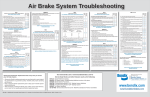
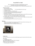
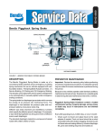
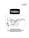
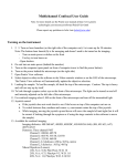
AIR PRESSURE BALANCE & THRESHOLD PRESSURE TESTS ® 1 2 __ __ __ __ __ __ __ __ __ __ __ Brake No. 1 3 __ __ __ __ __ __ __ __ __ __ __ 4 __ __ __ __ __ __ __ __ __ __ __ Axle Brake No. 2 Tractor Trailer Dolly Trailer Dolly Trailer VEHICLE DATA Vehicle Number Manufacturer Model, Year Comments 1. Number the axle and each brake on the axle of the vehicle being tested using the illustration. 2. All testing should be performed using both increasing (INC) and decreasing (DEC) air pressure and using our instructions. 3. When performing the Air Brake Pressure Balance Tests the pressure from only one chamber of a tandem can be used when the same relay valve delivers pressure directly to all four chambers on the tandem. 4. Record test results in the charts provided. Date: ________________________ Test Conducted By: ____________ GENERAL INSTRUCTIONS: Vehicle No: ___________________ Tractor #1 Trailer Conv. Dolly #2 Trailer Conv. Dolly #3 Trailer Air Pressure Balance and Threshold Pressure Tests Axle No. Air Brake Pressure Balance Test Service Chamber Pressure at Axle Increasing Pressures for Axle Nos. 1 2 3 4 5 6 Decreasing Pressures for Axle Nos. 7 1 2 3 4 5 5 Trailer Control Line 10 15 20 25 30 40 50 60 Foundation Brake Threshold Pressure Test BR.# INC DEC AVG BR.# 1 11 2 12 3 13 4 14 5 15 6 16 7 17 8 18 9 19 10 20 INC DEC AVG 6 7 VEHICLE PREPARATION FOR TESTING 1. Adjust all brakes equally using the vehicle manufacturers procedure. 2. Secure the vehicle on a level surface by means other than the brakes and charge the air system to governor cut-out (approximately 120 psi). Shut off engine. CAUTION: To avoid possible injury due to automatic application of the parking brakes during testing, it is recommended that the parking brakes be mechanically caged. 3. Check the vehicle or combination for excessive air system leakage. If the combined leakage exceeds the limits below, repair the sources of leakage before proceeding. Single Vehicle Tractor w/Trailer Tractor w/2 Trailers Brakes Released Brakes Fully Applied 4 psi in 2 mins. 6 psi in 2 mins. 6 psi in 2 mins. 8 psi in 2 mins. 8 psi in 2 mins. 10 psi in 2 mins. AIR BRAKE PRESSURE BALANCE TEST Objective: 3. Gradually apply the brakes via the brake valve and record the axle pressure in the increasing (INC) column of the axle #1 when brake valve primary delivery or trailer service (control) line pressure is at 5, 10, 15, 20, 25, 30, 40, 50 and 60 psi. Repeat procedure for each axle of the vehicle combination and record pressure readings on the chart. (See partial example.) IMPORTANT: Readings during this phase of the procedure should be taken with increasing air pressure only. Do not over apply and then release, as an inaccurate reading will occur. Release brakes fully and re-apply, if pressure is over applied. 4. Repeat the procedure using decreasing air pressure. Fully apply (75 psi application min.) the service brakes then gradually release and record the axle pressure in the decreasing (DEC) column of the appropriate axle when brake valve primary delivery or trailer service (control) line pressure is at 60, 50, 40, 30, 25, 20, 15, 10 and 5, respectively. Repeat the procedure for each axle and record the pressure readings on the chart. EXAMPLE: Air Brake Pressure Balance Test To determine the air pressure differences between the various axles of a single or combination vehicle. Equipment: Dual test gauge (use a gauge with a 0-150 psi range.) Testing: 1. Perform vehicle preparation and place the vehicle dash control valves in the normal over-the-road position. 2. If the vehicle being tested is a single unit, such as a straight truck or bus, install one half of the dual test gauge directly in the #1 or primary circuit delivery of the brake valve. For tractors or combination vehicles, install one half of the dual test gauge in the trailer service (control) line (between tractor and trailer). NOTE: This half of the test gauge will remain here for the duration of the test. Install the other half of the test gauge in a service brake chamber at axle #1. (Procedure will be repeated at each axle of the vehicle combination). NOTE: Test gauge connection must be between the air chamber and any control valve, ideally directly in or at the chamber. IMPORTANT: Readings during this phase of the procedure should be taken with decreasing air pressure only. Do not under shoot the pressure and partially reapply pressure as an inaccurate reading will result. Fully apply the brakes and exhaust down to the specified pressure. 5. When testing is complete, uncage the parking brakes unless you are proceeding to FOUNDATION BRAKE THRESHOLD PRESSURE TESTING. FOUNDATION BRAKE PRESSURE TESTING THRESHOLD Objective: To determine the air pressure required to make and release contact between the lining and drum at each foundation brake on the vehicle. Equipment: Test gauge (use a gauge with a 0-60 psi range.) Important: A low range (0-60 psi) pressure gauge is required for accurate data for the threshold pressure test. Using a higher range (0-100, or 0-150 psi) gauge can result in bad data. Testing: 1. Perform the vehicle preparation and place the vehicle dash controls in the normal over-the-road position. 2. If the vehicle being tested is a single unit, such as a straight truck or bus, install the test gauge directly in the #1 or primary circuit delivery of the brake valve. For tractors or combination vehicles, install the test gauge in the trailer service (control) line (between tractor and trailer). 3. Raise the axle until tires (wheel ends) are no longer in contact with the floor. 4. While manually rotating a wheel, gradually make a service brake application as registered on the gauge until braking torque (drag) occurs. Note the gauge air pressure and record it in the increasing (INC) column for the appropriate brake in the chart. 5. Increase service air pressure to 40 psi. While gradually decreasing the air pressure at the gauge, attempt to rotate the wheel. Note the gauge air pressure at which the wheel can be freely rotated and record that pressure in the decreasing (DEC) column for the appropriate brake in the chart. 6. Add the pressure recorded in the increasing (INC) and decreasing (DEC) columns together then divide by two. Record that value in the average (AVG) column for the appropriate brake. This average is the threshold pressure for that brake. EXAMPLE: Foundation Brake Threshold Pressure Test BR.# INC DEC AVG BR.# 1 9 3 6 11 2 8 3.5 6.5 12 DEC AVG 7. When testing is complete, uncage the parking brakes. RECOMMENDATIONS: Bendix recommends that all brake threshold pressures for all axles (average calculated value from the test results) be within a 2 psi range. This is to enable the brake force distribution to be within acceptable limits, especially at low brake application pressures. Industry studies have indicated that 80% of all brake applications made in actual service are below 20 psi. For pressure balance, on increasing pressures we recommend that the pressure recorded at each axle be within 2 psi of one another for trailer control line pressures of 10 to 40 psi. The decreasing pressures recorded should also be within 2 psi of one another in this pressure range. For axles fitted with special valves which enable the threshold pressure recommendation to be achieved or which proportion or limit the delivery to the chambers this recommendation is not valid. Under these conditions the specific application must be analyzed in more detail to understand the brake distribution. There are many factors that affect vehicle brake balance. Balancing the brake threshold pressures and the pressure at the chambers of all axles are important factors in achieving brake balance. However, this does not necessarily ensure even lining wear or brake force distribution. Consideration must also be given such factors as tire size, brake size, brake type, friction material and others. NOTE: The difference recorded in these tests can be attributed to specific vehicle design considerations. Before any brake system modification are made the test data should be reviewed by both the vehicle OEM and our Engineering Departments. For example: If the number in the increasing column was 9 and the number in the decreasing column was 3, then 9 +3 = 12, 12÷2 = 6, and 6 is recorded in the average column. BW1555 © Bendix Commercial Vehicle Systems LLC INC 11/2002 Printed in U.S.A.