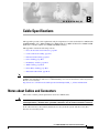
1
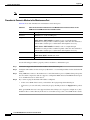
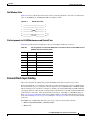
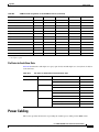
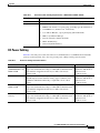
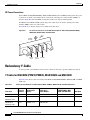
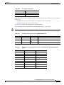
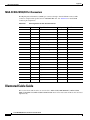
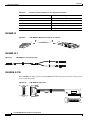
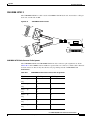
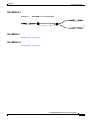
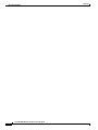
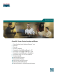
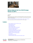
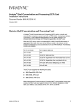
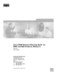
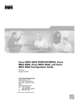
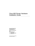
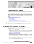
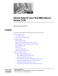
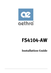
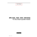
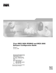
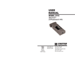
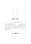
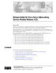
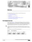
A P P E N D I X
B
Cable Specifications
This appendix provides cable requirements and pin assignments for cables used with Cisco MGX 8850
(PXM1E/PXM45), Cisco MGX 8850/B, Cisco MGX 8950, Cisco MGX 8830 and Cisco MGX 8830/B
multiservice switches and the Cisco MGX 8880 Media Gateway.
This appendix contains the following sections:
Note
•
Notes about Cables and Connectors, page B-1
•
Control and Clock Cabling, page B-3
•
External Alarm Cabling, page B-9
•
Power Cabling, page B-11
•
Redundancy Y-Cable, page B-14
•
Trunk Cabling, page B-16
•
Frame Relay Cabling, page B-17
•
Illustrated Cable Guide, page B-22
The information in this guide does not apply to the Cisco MGX 8850 (PXM1) switch. For MGX 8850
(PXM1) cable information, refer to Cisco MGX 8850 Edge Concentrator Installation and Configuration,
Release 1.1.3 located at:
http://www.cisco.com/univercd/cc/td/doc/product/wanbu/mgx8850/1_1_31/instconf/index.htm
Notes about Cables and Connectors
This section contains general explanations about Cisco MGX cables.
Warning
For NEBS Level 3 compliance to GR-1089 (Second-Level Lightning Surge and Intra-building AC Power
Fault Requirements), shielded cables, grounded at both ends, must be used on all metallic interfaces.
In all cable references, the transmit (Tx) direction is away from the system, and the receive (Rx)
direction is toward the system.
Cisco MGX 8800/8900 Series Hardware Installation Guide
Releases 2 - 5.2, Part Number OL-4545-01, Rev. H0, May 2006
B-1
Appendix
Notes about Cables and Connectors
Cable and Connector Naming Conventions
The suffix to the model number indicates the length of the cable. For example, 5610-50 indicates a
50-foot cable. Sometimes the suffix indicates the cable length in inches, rather than feet. This typically
occurs on Y-cables or adaptor cables.
Some entries in the cable tables include the gender of the connector and the number of pins. For example,
EIA/TIA-232/M25-M25 indicates a cable terminated with a male DB-25 connector at each end.
Cable Lengths
Cables are available in standard lengths of 10 feet (3 meters), 25 feet (7.6 meters), 50 feet (15 meters),
75 feet (22.8 meters), and 100 feet (30 meters). Lengths of 100 feet (30 meters) to 600 feet (183 meters)
can be specially ordered.
Standard Cisco MGX 8850 (PXM1E/PXM45), MGX 8850/B, and MGX 8880 Cables
The standard cables that Cisco can supply for the Cisco MGX 8850 (PXM1E/PXM45) and MGX 8850/B
systems appear in Table B-1.
Table B-1
Standard Cisco MGX 8850 and MGX 8850/B Cables Available from Cisco
Model Number
Description
Usage
CAB-T3E3-PL-AD
75 ohms coax/SMB-BNC
T3 or E3 trunk interface
ASSY CBL SMB (M) to BNC (F) T3 or E3 trunk interface
CAB-T3E3-PL-AD-6
T3/E3 SMB to SMB Posi-Lok
Redundant usage
Posi-Lok SMB to BNC 6 Ad
T3 or E3 trunk interface
CAB-T3E3-PL-CE-AD T3/E3 SMB-BNC Posi-Lok A
T3 or E3 trunk interface (International)
CAB-T3E3-PL-CE-Y
T3/E3 SMB-BNC Posi-Lok Y
Redundant usage (International)
CAB-SMB-BNC-Y
Posi-lok SMB to BNC Y Ca
Redundant usage
CAB-T3E3-PL-Y-6
Posi-lok SMB to BNC 6 Y
Redundant usage
CAB-MCC-T1E1
CAB-MCC-T1E1-Y
Mini-coaxial (MCC) to BNC
cable
E1 interface
E1 interface (Redundant usage)
CAB-RBBN-16-T1E1
CAB-RBBN-16-T1E1Y
36-pin to 50-pin straight cable
with RBBN connector
T1 or E1 interface
T1 or E1 interface (Redundant usage)1
5620
EIA/TIA-232/M25-F25
PXM-UI-S3 maintenance port to control
terminal, Cisco WAN Manager, or
external window device
5621
EIA/TIA-232/M25-M25 special
Control or maintenance port to modem
Ground cable
(customer-supplied)
DC power.
See Table B-13 for details.
Cisco MGX 8800/8900 Series Hardware Installation Guide
B-2
Releases 2 - 5.2, Part Number OL-4545-01, Rev. H0, May 2006
Appendix
Control and Clock Cabling
Table B-1
Standard Cisco MGX 8850 and MGX 8850/B Cables Available from Cisco (continued)
Model Number
Description
Usage
Molex-pigtail
(customer-supplied)
DC power.
See Table B-13 for details.
Spade lug-pigtail
(customer-supplied)
DC power.
See Table B-13 for details.
1. Two cables required per back card, one TX and one RX.
Standard Cisco MGX 8950 Cables
The standard cables that Cisco can supply for the Cisco MGX 8950 system appear inTable B-2.
Table B-2
Standard Cisco MGX 8950 Cables Available from Cisco
Model Number
Description
Usage
CAB-T3E3-PL-AD-6
75 Ω coax/SMB-BNC, 6 feet
T3 or E3 trunk interface
ASSY CBL SMB(M) to BNC(F)
T3 or E3 trunk interface
T3/E3 SMB to SMB Posi-Lok
Redundant usage
Posi-lok SMB to BNC 6 Ad
T3 or E3 trunk interface
CAB-T3E3-PL-AD-6
CAB-T3E3-PL-CE-AD T3/E3 SMB-BNC Posi-lok A
T3 or E3 trunk interface
CAB-T3E3-PL-CE-Y
T3/E3 SMB-BNC Posi-lok Y
Redundant usage
CAB-SMB-BNC-Y
Posi-lok SMB to BNC Y Ca
Redundant usage
CAB-T3E3-PL-Y-6
Posi-lok SMB to BNC 6 Y
Redundant usage
5620
EIA/TIA-232/M25-F25
PXM-UI-S3 maintenance port to control
terminal, Cisco WAN Manager, or
external window device
5621
EIA/TIA-232/M25-M25 special
Control or maintenance port to modem
5601
Ground cable
DC power
5670
Molex-pigtail
DC power
5671
Spade lug-pigtail
DC power
Control and Clock Cabling
This section describes the cables that can connect to the PXM-UI-S3 or PXM-UI-S3/B user interface
back card.
Maintenance and Control Ports
The maintenance (or modem) port and the control (or console) port connect a switch or gateway to an
ASCII terminal, workstation, or modem for remote alarm reporting or system monitoring. These ports
are labeled MP or CP on the user interface back card. See Figure 2-63 on page 2-121 and Figure 2-64
on page 2-122 for the locations of these ports. Table B-3 provides cabling details.
Cisco MGX 8800/8900 Series Hardware Installation Guide
Releases 2 - 5.2, Part Number OL-4545-01, Rev. H0, May 2006
B-3
Appendix
Control and Clock Cabling
Note
The PXM-UI-S3/B user interface card does not have a maintenance port.
Procedure to Connect a Modem to the Maintenance Port
Table B-3 lists cable information for maintenance and control ports.
Table B-3
Cable and Connector Information for the Maintenance and Control Ports on the
PXM-UI-S3 and PXM-UI-S3/B User Interface Cards
Cable Parameter
Description
Interface
EIA/TIA-232—both are DTE ports.
Suggested cable
MGX 8950: Uses only 8 conductor
MGX 8850 or MGX 8850/B: 24 AWG, 25-wire. A straight-through
EIA/TIA-232 cable provides a terminal or printer connection. For an interface
with modems on either port, a null modem cable might be necessary.
MGX 8830 or MGX 8830/B: 24 AWG, 8-wire. A straight-through
EIA/TIA-232 cable provides a terminal or printer connection. For an interface
with modems on either port, a null modem cable might be necessary.
Cable connector
MGX 8850 and MGX 8950: RJ-48, subminiature, male.
MGX 8830: RJ-45, subminiature, male.
Maximum cable length 50 feet (15.24 m).
Use the following procedure to properly connect a modem to a maintenance port.
Step 1
Connect the suggested cable from the modem to the maintenance port.
Step 2
Configure an IP address for the serial port (s10) and also a second unique address for the destination IP
address.
Step 3
Using 9600 baud, connect to the modem. Use a serial line interface protocol (SLIP) client package that
does not enable compression and also supports a configurable EOF character. The MGX switch expects
to see an EOF character of 300 in base 8.
Step 4
Try to telnet or ping the destination IP address configured.
•
If the correct SLIP client is used, you should see the login prompt when telnetting in.
•
If incorrect, you can still verify connectivity is up by checking statistics on dspipif s10 for packets
in.
If the special EOF character is not supported, then after 576 bytes, it is logged as an input error. (You
should be able to connect directly from a PC or via modem as long as the correct SLIP client is used.)
Cisco MGX 8800/8900 Series Hardware Installation Guide
B-4
Releases 2 - 5.2, Part Number OL-4545-01, Rev. H0, May 2006
Appendix
Control and Clock Cabling
Null Modem Cable
Figure B-1 shows a null modem cable that is used for connecting modems to the control or maintenance
ports on the PXM-UI-S3 and PXM-UI-S3/B User Interface Cards.
Null Modem Cable
1
1
7
7
2
2
3
3
6
6
20
20
S6189
Figure B-1
Pin Assignments for RJ-48 Maintenance and Control Ports
Table B-4 provides the pin assignments for the associated RJ-48 and RJ-45 connectors.
Table B-4
Pin Assignments for the RJ-48 Maintenance and Control Ports on the PXM-UI-S3 and
PXM-UI-S3/B User Interface Cards
Pin No.
Name
Description
1
RTS out
Request to send
2
DTR out
Data terminal ready
3
TxD
Transmit data
4
GND
Chassis ground
5
GND
Chassis ground
6
RxD
Receive data
7
DSR
Data set ready
8
CTS
Clear to send
External Clock Input Cabling
This section explains the cabling that provides the MGX switch with an external clock source.
If external equipment or a local digital central office provides synchronization to the Cisco MGX switch,
the external clock source is connected to the user interface back card (PXM-UI-S3 or PXM-UI-S3/B).
The user interface back card has two external clock input ports labeled EXT CLK1 and EXT CLK2 that
can support either T1 or E1 external clock input, but not both. That is, both EXT CLK1 and EXT CLK2
clocks must be set the same, either T1 or E1. The clock may be 1.544 Mbps or 2.048 Mbps. Refer to
Table 2-44 on page 2-120 for information about which switch is compatible with which user interface
back card, and see Figure 2-63 on page 2-121 and Figure 2-64 on page 2-122 for locations of the external
clock ports.
The PXM-UI-S3 or PXM-UI-S3/B cards go into slots 7 and 8 for the following switches:
•
MGX 8850 (PXM1E/PXM45) and MGX 8850/B
•
MGX 8950
Cisco MGX 8800/8900 Series Hardware Installation Guide
Releases 2 - 5.2, Part Number OL-4545-01, Rev. H0, May 2006
B-5
Appendix
Control and Clock Cabling
The PXM-UI-S3 or PXM-UI-S3/B cards go into slots 1 and 2 for the MGX 8830 and MGX 8830/B
switches.
For redundancy where one user interface back card is present, connect to both ports, using EXT CLK1
as the primary source and EXT CLK2 as the secondary source.
For redundant PXM configurations where two user interface back cards are present, use a Y-cable to
connect to the EXT CLK1 input of Slot 7 and the EXT CLK1 input of Slot 8. For BITS source protection,
connect another Y-cable to the EXT CLK2 input of Slot 7 and the EXT CLK2 input of Slot 8. (For
MGX 8830 switches, these cards would be in slots 1 and 2.)
Cable Specifications for Y-Cables and Cable Adapters for Clocking
There are two types of Y-cables for clocking:
Note
•
One type has an RJ-45 plug at the single end, and RJ-45 connectors at the Y ends
•
One type has a BNC coax connector at the single end, and RJ-45 connectors at the Y ends
In systems with redundant PXM cards and an external clock source, the single external clock source
should be connected to both PXM-UI-S3 cards using a short Y-cable.
A wire-wrap adapter can be used for clocking. See “Connect the External Clock Using a Wire-Wrap
Adapter” section on page B-7.
A cable adaptor with an RJ-45 connector on one end and a BNC coax connector at the other end can be
used for clocking.
The maximum cable length is 533 feet (162.46 m) between the MGX switch and the first repeater or
channel service unit (CSU). Selection of cable length equalizers is used. Wire build-out is required.
T1/E1 Clock Input Cable Information
The T1 RJ-48 clock port can accept either a T1 or an E1 Building Integrated Timing Supply/Synchronous
Equipment Timing Source (BITS/SETS) clock input signal. The E1 RJ-45 clock port can accept twisted
pair or 75-ohm coaxial cable. See Table B-5 for cable and signal information for the external clock.
Table B-5
Cable and Signal Information for the External Clock Ports on the PXM-UI-S3 or
PXM-UI-S3B Card
Carrier
Cable Media
Signal Type (Data or Sync)
T1
22 AWG, twisted pair with shield. 100-ohm
Data
E1
22 AWG, twisted pair with shield. 120-ohm, bipolar
Data
or
75-ohm coaxial cable
Building Integrated Timing Supply (BITS) Clock Connector Pin Assignments
For MGX 8850 (PXM1E/PXM45), MGX 8850/B, MGX 8950 switches, and the MGX 8880 Media
Gateway, the RJ-48 BITS clock connector has a 100-ohm termination for T1 and a 120-ohm termination
for E1.
Cisco MGX 8800/8900 Series Hardware Installation Guide
B-6
Releases 2 - 5.2, Part Number OL-4545-01, Rev. H0, May 2006
Appendix
Control and Clock Cabling
Note
Make sure that the 100-ohm termination is selected when you configure the clocks for T1. You need to
connect only the RX Ring, the RX Tip, and the Ground (pins 4, 5, and 6).
Table B-6 shows the pin assignment for the RJ-48 BITS clock connector.
Table B-6
Pin Assignments for the RJ-48 BITS Clock Connector
Pin No.
Signal
1
TX ring
2
TX tip
3
Ground
4
RX ring
5
RX tip
6
Ground1
7
TTP ring
8
TTP tip
1. No connection on the MGX 8830 and MGX 8830/B
Connect the External Clock
The section provides the following installation procedures for connecting the external clock:
•
“Connect the External Clock Using an RJ-45 Connection” section on page B-7
•
“Connect the External Clock Using a Wire-Wrap Adapter” section on page B-7
Connect the External Clock Using an RJ-45 Connection
Complete the following steps to connect the external clock.
Tip
We recommend that you label each data cable at both ends to identify its source and destination.
Step 1
Verify that you have a PXM-UI-S3 or PXM-UI-S3/B back card installed in slots 7 and 8 in the upper rear
bay of the switch. (In an MGX 8830 and MGX 8830/B, these cards would be in slots 1 and 2.)
Step 2
Connect the cable connector to the EXT CLK 1 port on the user interface back card.
Step 3
Connect the other end of the cable to the clock source.
Step 4
Repeat Step 1 through Step 3 as necessary for each external clock connection.
Connect the External Clock Using a Wire-Wrap Adapter
The optional RJ-45 to wire-wrap adapter (PXM-WIREWRAP=) connects an external building integrated
timing supply (BITS) clock source to the PXM-UI-S3 or PXM-UI-S3/B using s wire-wrap connection
instead of an RJ-45 connection (see Figure B-2).
Cisco MGX 8800/8900 Series Hardware Installation Guide
Releases 2 - 5.2, Part Number OL-4545-01, Rev. H0, May 2006
B-7
Appendix
Control and Clock Cabling
Optional RJ-45 to Wire-wrap
52804
Figure B-2
Note
The eight pins of the adapter are marked and have a one-to-one correlation to the eight lines on the RJ-45
connector.
When you install the RJ-45 to wire-wrap adapter, you do not need to remove the card from its slot or
turn off the power. However, you should wire-wrap the cable conductors to the applicable pins on the
adapter before you plug the adapter into the card.
Complete the following steps to connect the external clock using the wire-wrap adapter:
Step 1
Remove the pin cover from the adapter (see Figure B-3). The pin cover provides ESD shielding.
Removing the Pin Cover from the Adapter
52803
Figure B-3
Insert the shielded clock source cable through the hole of the pin cover. See Figure B-4.
Note
You must use a shielded clock source cable to ensure EMI containment.
Figure B-4
Note
Inserting the Cable through the Pin Cover
8
4
7
3
6
2
5
1
52805
Step 2
The length of the exposed (unshielded) wires should be 2 to 4 inches. The maximum allowable
length is 4 inches.
Cisco MGX 8800/8900 Series Hardware Installation Guide
B-8
Releases 2 - 5.2, Part Number OL-4545-01, Rev. H0, May 2006
Appendix
External Alarm Cabling
Step 3
Use a wire-wrapping tool to wrap the shield drain wire to the ground pin (pin 3 or 6) of the adapter. The
shield drain wire is the bare wire shown in Figure B-5.
Figure B-5
Wires Wire-Wrapped to Pins
8
7
6
3
2
1
53281
5
4
Step 4
Use a wire-wrapping tool to wrap the two remaining wires to the pin of the adapter.
Step 5
Slide the pin cover over the pins and onto the body of the adapter after all of the wires are connected.
Step 6
Insert the RJ-45 connector of the adapter into the EXT CLK1 or EXT CLK2 port on the PXM-UI-S3 or
PXM-UI-S3/B.
Step 7
If the faceplate of the PXM-UI-S3 or PXM-UI-S3/B has a mating tapped hole, hand tighten the
strain-relief screw to provide additional strain relief.
Step 8
Connect the opposite end of the shielded cable to the external BITS clock source.
External Alarm Cabling
The network alarm cable connects to the ALARM connector on the PXM-UI-S3 or PXM-UI-S3/B user
interface card.
Alarm Cable Information
This section describes cables, connectors, and pin assignments for network alarm cabling.
Alarm Cable Information for MGX Switches
Table B-7 describes the Alarm cable used for the MGX 8850 (PXM1E/PXM45), MGX 8850/B,
MGX 8950, MGX 8830 and MGX 8830/B switches.
Table B-7
External Alarm Cable and Connector Information for MGX Switches
Cable Parameter
Description
Interface
Dry-contact relay closure
Wire
24 AWG, shielded, 6-pair
Connector
DB-15, subminiature, male
Cisco MGX 8800/8900 Series Hardware Installation Guide
Releases 2 - 5.2, Part Number OL-4545-01, Rev. H0, May 2006
B-9
Appendix
External Alarm Cabling
Alarm Connector Pin Assignments
Table B-8 describes the Alarm connector pin assignments for the different MGX multiservice switches.
Table B-8
Pin Assignments for the DB-15 ALARM Connector
MGX 8850 (PXM1/PXM45), MGX 8850/B,
MGX 8950 Only
MGX 8830, MGX 8830/B Only
Pin # Alarm
Pin # Alarm
Description
Normally open
Description
1
Audible—critical Normally on
1
Audible—Major
2
Visual—critical
Normally on
2
3
Visual—critical
Normally off
3
Audible—Minor
Normally open
4
Audible—major
Common
4
Visual—Major
Normally open
5
Visual—major
Common
5
6
Audible—minor
Normally on
6
Visual—Minor
Normally open
7
Visual—minor
Normally on
7
unused
n.c.
8
Visual—minor
Normally off
8
unused
n.c.
9
Visual—critical
Normally off
9
Normally closed
10
Visual—critical
Common
10
Normally closed
11
Audible—major
Normally on
11
Common
12
Visual—minor
Normally on
12
Normally closed
13
Visual—major
Normally off
13
Normally closed
14
Audible—minor
Common
14
Common
15
Visual—minor
Common
15
Common
Common
unused
n.c.
Connector Pin Functions for Audio and Visual Alarms
Table B-9 shows the pin numbers and functions on the ALARM connector on the PXM-UI-S3 and
PXM-UI-S3/B user interface back card.
Table B-9
•
When Audio Alarm is enabled, the Audio Alarm On and Audio Alarm Common pins are closed
(short circuit).
•
When Audio Alarm is disabled, the Audio Alarm On and Audio Alarm Common pins are opened
(open circuit).
•
When Visual Alarm is enabled, the Visual Alarm On and Visual Alarm Common pins are closed,
and the Visual Alarm Off pin is opened.
•
When Visual Alarm is disabled, the Visual Alarm Off and Visual Alarm Common pins are closed,
and the Visual Alarm On pin is opened.
PXM-UI-S3 Pin Assignment on the ALARM Connector
Pin Name
Pin No.
Audio Enable
1
Critical Audio Alarm On
1
S
Critical Audio Alarm Common
9
Common
Audio Disable
O
2
Common
Visual Enable
Visual Disable
—
—
—
—
Cisco MGX 8800/8900 Series Hardware Installation Guide
B-10
Releases 2 - 5.2, Part Number OL-4545-01, Rev. H0, May 2006
Appendix
Power Cabling
Table B-9
PXM-UI-S3 Pin Assignment on the ALARM Connector (continued)
Pin Name
Pin No.
Audio Enable
Audio Disable
Visual Enable
Visual Disable
Critical Visual Alarm On
2
—
—
S
O
Critical Visual Alarm Common
10
—
—
Common
Common
Critical Visual Alarm Off
3
—
—
O
S
Major Audio Alarm On
11
S
O
—
—
Major Audio Alarm Common
4
Common
Common
—
—
Major Visual Alarm On
12
—
—
S
O
Major Visual Alarm Common
5
—
—
Common
Common
Major Visual Alarm Off
13
—
—
O
S
Minor Audio Alarm On
6
S
O
—
—
Minor Audio Alarm Common
14
Common
Common
—
—
Minor Visual Alarm On
7
—
—
S
O
Minor Visual Alarm Common
15
—
—
Common
Common
Minor Visual Alarm Off
8
—
—
O
S
1. S = Signal is shorted with Common
2. O = Signal is opened
Pin States for Each Alarm State
Table B-10 summarizes which pins are open (open circuit) and which pins are closed (short circuit) for
each alarm state.
Table B-10
Pin States for Each Audio and Visual Alarm State
Alarm
Alarm State
Pin
Pin State
Audio alarm
Enabled
Audio Alarm On
Closed
Audio Alarm Common
Closed
Audio Alarm On
Open
Audio Alarm Common
Open
Visual Alarm On
Closed
Visual Alarm Common
Closed
Visual Alarm Off
Open
Visual Alarm On
Open
Visual Alarm Common
Closed
Visual Alarm Off
Closed
Disabled
Visual alarm
Enabled
Disabled
Power Cabling
This section provides information on providing AC and DC power cabling for the MGX switch.
Cisco MGX 8800/8900 Series Hardware Installation Guide
Releases 2 - 5.2, Part Number OL-4545-01, Rev. H0, May 2006
B-11
Appendix
Power Cabling
AC Power Cabling—MGX 8850 (PXM1E/PXM45), MGX 8850/B and MGX 8880
We provide a 6-foot (1.8-meter) AC power cord for an AC-powered system. This AC power cord is
available for the following countries:
•
Argentina: Cisco Part Number CAB-ACR
•
Australia: Cisco Part Number PWRCD-ANZ
•
Continental Europe: Cisco Part Number PWRCD-EU
•
Great Britain: Cisco Part Number PWRCD-GBI
•
Ireland: Cisco Part Number PWRCD-GBI
•
Italy: Cisco Part Number PWRCD-IT
•
Japan: Cisco Part Number PWRCD-NA
•
New Zealand: Cisco Part Number PWRCD-ANZ
•
North America: Cisco Part Number PWRCD-NA (NEMA L6-20 twistlock plug)
For the number of power cords that support your MGX 8850 (PXM1E/PXM45), MGX 8850/B and
MGX 8880 switches, see Table 1-5.
AC Power Cabling—MGX 8950
We provide a 10-foot (3 meter) AC power cord for an AC-powered system. This AC power cord is
available for the following countries:
•
Europe: Cisco Part Number PWRCD-30A-EU
•
North America: Cisco Part Number PWRCD-30A-NA
Table B-11 shows the power cords requirements for the MGX 8950 switch.
Table B-11
AC Power Cable and Plug Requirements—MGX 8950
Cable Parameter
Description
Cable
Provided with 10 feet (2.3 m) of 3-conductor wire with plug.
Plug (customer end)
30A NEMA L6-30, 3-prong plug (United States)
For international use, the line cord is hard-wired with an IEC309 plug.
For the number of power cords that support your MGX 8950 switch, see Table 3-14.
AC Power Cabling—MGX 8830 and MGX 8830/B
Either Cisco or the customer can provide the AC power cord. See Table B-12 for the power cords that
Cisco can supply. In addition, you can special-order AC cables with other plugs or different lengths. If
you want to construct the power cord, it must mate with an IEC320 (C-14) 10/15A male receptacle on
the back of the AC power module.
Cisco MGX 8800/8900 Series Hardware Installation Guide
B-12
Releases 2 - 5.2, Part Number OL-4545-01, Rev. H0, May 2006
Appendix
Power Cabling
Table B-12
AC Power Cable and Plug Requirements—MGX 8830 and MGX 8830/B
Cable Parameter
Description
Cable
Provided with 8 feet (2.3 meters) of 3-conductor wire with plug.
Plug (customer end)
•
20A NEMA L6-20P, twist lock plug (United States)
•
NEMA5-15P 125V/15 A 3-prong plug, grounding type (North America)
•
15A NEMA 5-15 (domestic U.S. and Canada)
•
13 A 250 Vac BS1363, 3-prong fused plug (UK and Ireland)
•
CEE 7/7 (Continental Europe)
•
AS3112 (Australia and New Zealand)
•
CEI23-16/VII (Italy)
•
125V/15A (North America)
DC Power Cabling
Table B-13 lists DC power cable and connector recommendations for each MGX switch and media
gateway system. Typically, Cisco does not provide power cabling for DC-powered systems.
Table B-13
DC Power Cabling Recommendations
Switch Name
DC Cable Wiring
DC Cable Connection
MGX 8850
(PXM1E/PXM45) and
MGX 8850/B
Three conductor, 6 AWG (10 square mm) or larger, solid or stranded
copper wire with insulation rating for 140°F (60°C) minimum with
wire insulation stripped back 0.25 in (6.35 mm) at the chassis
connector end.
Panduit terminal lug (part
number LC AS6-10-L) or
equivalent to fit
no. 10-32 screws.
MGX 8950
Three conductor, 6 AWG (10 square mm) recommended wire gauge,
min. 60 degrees Celsius insulation rating, copper conductors only.
Panduit LC AS6-10-L terminal lug or equivalent to fit no. 10-32
screws.
Panduit terminal lug (part
number LC AS6-10-L) or
equivalent to fit
no. 10-32 screws.
MGX 8830 and
MGX 8830/B
Three conductor, 10 AWG recommended wire gauge, solid or stranded EURO Block.
copper wire with insulation rating for 140°F (60°C) minimum with
wire insulation stripped back 0.25 in (6.35 mm) at the chassis
connector end.
MGX 8880 Media
Gateway
Three conductor, 6 AWG (10 square mm) or larger, solid or stranded
copper wire with insulation rating for 140°F (60°C) minimum with
wire insulation stripped back 0.25 in (6.35 mm) at the chassis
connector end.
Panduit terminal lug (part
number LC AS6-10-L) or
equivalent to fit
no. 10-32 screws.
Cisco MGX 8800/8900 Series Hardware Installation Guide
Releases 2 - 5.2, Part Number OL-4545-01, Rev. H0, May 2006
B-13
Appendix
Redundancy Y-Cable
DC Power Connections
For the MGX 8850 (PXM1E/PXM45), MGX 8850/B, MGX 8950, and MGX 8880 systems, DC power
connections are made to the terminal block on the back of the DC power entry modules (PEMs), as
shown in Figure B-6. The DC PEMs are installed on the back of the air intake plenum.
For MGX 8830 or MGX 8830/B systems, DC power connections are made to the DC power entry
modules (PEMs) at the rear of the switch.
See Table B-13 for details on DC power cabling and connections.
Figure B-6
DC Power Connections on DC PEM Terminal Block—MGX 8850 (PXM1E/PXM45),
MGX 8850/B, MGX 8950, and MGX 8880
-48V
38228
RTN
48 VDC
return
Safety
ground
– 48 VDC
Redundancy Y-Cable
Y-cables provide card redundancy. This section contains Y cable Cisco product numbers by switch.
Y Cables for MGX 8850 (PXM1E/PXM45), MGX 8850/B and MGX 8880
Table B-14 lists the Y-cables used with various MGX 8850 (PXM1E/PXM45), MGX 8850/B, and MGX
8880 cards.
Table B-14
Y-Cable Product Numbers for MGX 8850 (PXM1E /PXM45), MGX 8850/B, and MGX 8880 Cards
Type/Standard
Interface
Y Cable Cisco
Product Number
MGX 8850
(PXM1E/PXM45), MGX
8850/B, and MGX 8880
CAB-SSIO-RJ45
x
Back Card
Connector
Hardware
PXM-UI-S3/B
RJ-45
PXM-UI-S3
RJ-45
EIA/TIA-232
CAB-5686-04
x
RJ-45
T1 BITS clock
CAB-5686-04
x
MGX 8950
x
PXM-UI-S3/B
PXM-UI-S3
PXM-UI-S3/B
Cisco MGX 8800/8900 Series Hardware Installation Guide
B-14
Releases 2 - 5.2, Part Number OL-4545-01, Rev. H0, May 2006
Appendix
Redundancy Y-Cable
Table B-14
Y-Cable Product Numbers for MGX 8850 (PXM1E /PXM45), MGX 8850/B, and MGX 8880 Cards (continued)
Back Card
Connector
Hardware
Type/Standard
Interface
Y Cable Cisco
Product Number
MGX 8850
(PXM1E/PXM45), MGX
8850/B, and MGX 8880
PXM-UI-S3
RJ-45
E1 BITS clock
CAB-5686-04
x
RJ-45
E1 BITS clock
CAB-5686-04
x
DB-15
Alarm output
CAB-5607-10 (10-in. Y)
x
x
PXM-HD
SC
MMF
CAB-MMF-Y-SC
x
x
BNC-3T3-M
BNC
75 ohm, coaxial
CAB-BNC-Y/B
x
AXSM
LC
SMF
CAB-MMF-LC
CAB-MMF-LC-Y
x
x
AXSM
MTRJ
MMF
CAB-MTRJ-SC-MM-3M
CAB-MTRJ-SC-MM-5M
x
x
AXSM
SC
SMF
CAB-SMF-Y-SC
CAB-SMF-SC (several)
x
x
AXSM
MCC
Miniature coaxial
cable, E1
CAB-MCC-BNC
CAB-MCC-BNC-Y
x
RBBN
T1/E1
CAB-RBBN-16-T1E1-Y
CAB-RBBN-16-T1E11
x
PXM-UI-S3
RJ45
EIA/TIA-232
CAB-5684-04
PXM-UI-S3
RJ45
EIA/TIA-232
CAB-5684-04
PXM-UI-S3
RJ45
T1 BITS Clock
CAB-5686-04
PXM-HD
SC
SMF
CAB-SMF-Y-SC
MGX 8950
PXM-UI-S3/B
PXM-UI-S3
PXM-UI-S3/B
PXM-UI-S3
PXM-UI-S3/B
PXM1E
AXSM
PXM1E
1. Two cables required per back card, one TX and one RX.
Y Cables for MGX 8950
Table B-15 lists the Y-cables used with various Cisco MGX 8950 cards.
Table B-15
Y-Cable Product Numbers for MGX 8950 Cards
MGX 8950 Card
Connector
Hardware
Type/Standard
Interface
Y Cable Product Number
PXM-UI-S3
RJ45
EIA/TIA-232
CAB-5684-04 (6-inch Y)
PXM-UI-S3
RJ45
EIA/TIA-232
CAB-5684-04
PXM-UI-S3
RJ45
T1 BITS Clock
CAB-5686-04 (6-inch Y)
PXM-UI-S3
DB15
Alarm Output
CAB-5607-10 (10-inch Y)
Cisco MGX 8800/8900 Series Hardware Installation Guide
Releases 2 - 5.2, Part Number OL-4545-01, Rev. H0, May 2006
B-15
Appendix
Trunk Cabling
Table B-15
Y-Cable Product Numbers for MGX 8950 Cards (continued)
MGX 8950 Card
Connector
Hardware
Type/Standard
Interface
AXSM
LC
SMF
AXSM
MTRJ
MMF
AXSM
SC
MMF
Y Cable Product Number
CAB-MMF-Y-SC
Trunk Cabling
This section provides information about T3 and E3 trunk cabling.
T3 Trunk Cabling
A trunk cable connects each T3 port on the SMB-8T3 back card to a T3 port on the colocated MGX 8220
node. See Table B-16 for information about the T3 trunk cable wiring and connector.
Table B-16
T3 Trunk Cable and Connector Information
Cable Parameter
Description
Type
75-ohm coaxial cable (RG-59 B/U for short runs; AT&T 734A for longer
runs). Two per T3 line (transmit and receive).
Maximum length
450 feet between the Cisco MGX 8850 or MGX 8950 switch and the DSX-3.
450 feet between the Cisco MGX 8830 switch and the other equipment.
Connector
Terminated in male SMB. Rx is received from trunk; Tx is transmitted to
trunk.
See Table B-17 for details on SMB pin functions.
Table B-17
T3 Connector Pin Functions
Connector
Description
Rx SMB
Receive T3 from trunk
Tx SMB
Transmit T3 to trunk
E3 Trunk Cabling
A trunk cable connects each E3 port on the SMB-8E3 back card to an E3 port on the colocated MGX
8220 node. See Table B-18 for information about the E3 trunk cable wiring and connector.
Cisco MGX 8800/8900 Series Hardware Installation Guide
B-16
Releases 2 - 5.2, Part Number OL-4545-01, Rev. H0, May 2006
Appendix
Frame Relay Cabling
Table B-18
E3 Trunk Cable and Connector Information
Cable Parameter
Description
Type
75-ohm coaxial cable (RG-59 B/U for short runs, AT&T 734A for longer
runs). Two per E3 line (transmit and receive).
Maximum length
100 feet between the Cisco MGX 8850 switch and the CS/DSU.
450 feet maximum between the Cisco MGX 8950 switch and the DSX-3.
Connector
Terminated in male SMB. Rx is received from trunk; Tx is transmitted to
trunk.
See Table B-19 for details on SMB pin functions.
Table B-19
E3 Connector Pin Functions
Connector
Description
Rx SMB
Receive E3 from trunk
Tx SMB
Transmit E3 to trunk
Frame Relay Cabling
This section describes the cabling and connector pin assignments for the Frame Relay cards.
Note
The Frame Relay Cabling section does not apply to the MGX 8950 switch or MGX 8880 gateway.
T1 Cabling
T1 trunk cables connect the customer DSX-1 cross-connect point or T1 channel service unit (CSU) to
the Cisco MGX 8850 or MGX 8830 switch at the T1 back card.
See Table B-20 for T1 trunk cable and connector information.
Table B-20
T1 Trunk/Circuit Line Cable and Connector Specifications
Cable Parameter
Description
Cable type
Western Electric 22 AWG, ABAM individually shielded twisted pair (100
ohm balanced). Two pair per T1 line (one transmit and one receive).
Cable connector
RJ-48C male. (Figure B-7 illustrates the RJ-48 connector schematic.)
Maximum cable length
655 feet (199.64 meters) maximum between the Cisco MGX 8850 or
MGX 8830 switch and the first repeater or CSU. A selection of cable
length equalizers is available.
Cisco MGX 8800/8900 Series Hardware Installation Guide
Releases 2 - 5.2, Part Number OL-4545-01, Rev. H0, May 2006
B-17
Appendix
Frame Relay Cabling
See Table B-21 for pin assignments for the RJ-48C T1 and E1 connector.
Table B-21
Note
RJ-48C T1 and E1 Connector Pin Assignments
Pin No.
Description
1
Transmit Ring
2
Transmit Tip
3
Transmit Shield
4
Receive Tip
5
Receive Ring
6
Receive Shield
Transmit direction is toward the T1 trunk.
See Figure B-7 for an RJ-48 connector schematic.
Figure B-7
RJ-48 Connector Schematic
RJ-48 Pins
In
In
TTIP
TRNG
2
1
5
4
RTIP
RRNG
Out
Out
3
shield
shield
26270
6
Cisco MGX 8800/8900 Series Hardware Installation Guide
B-18
Releases 2 - 5.2, Part Number OL-4545-01, Rev. H0, May 2006
Appendix
Frame Relay Cabling
E1 Cabling
E1 trunk cables connect the customer DSX-1 cross-connect point or E1 CSU to the MGX switch at the
FRSM E1 back card (SMB-8E1).
See Table B-22 for E1 trunk cable and connector information.
Table B-22
E1 Trunk/Circuit Line Cable and Connector Specification
Cable Parameter
Description
Cable type
(BNC-8E1)
75-ohm coax cable for unbalanced connection. Two cables or pairs
(one transmit and one receive) per E1 line.
Cable connector
16 female SMB for unbalanced connection.
Maximum cable
length
Approximately 100 meters (328 feet) maximum between the Cisco MGX 8850
or Cisco MGX 8830 switch and the first repeater or CSU. A selection of cable
length equalizers is available.
See Table B-21 for pin assignments for the RJ-48C T1 and E1 connector.
See Table B-23 for pin assignments for the RJ-48C E1 connector—unbalanced.
Table B-23
RJ-48C E1 Connector Pin Assignments—Unbalanced
Connector
Description
Rx BNC
Receive E1 from trunk
Tx BNC
Transmit E1 to trunk
MGX-12IN1-S8 Back Card Cables
The back card for the MGX-FRSM-HS2/B is the MGX-12IN1-S8. Each port on the back card connects
through a DTE version or DCE version of the Cisco 12IN1 cable. The signal on the back card depends
on whether the back card connector is DTE or DCE and whether the back card has been set as X.21 or
V.35 as shown in Table B-24.
For the signals on the back card, see Table B-25 and Table B-26. The tables show the signal acronym,
signal name, and signal source.
Table B-24
12IN1-S8 and 12IN1-S4 Back Card Cable Types
Cable
Type
X.21
V.35
DCE
X.21 DCE
V.35 DCE
DTE
X.21 DTE
V.35 DTE
Cisco MGX 8800/8900 Series Hardware Installation Guide
Releases 2 - 5.2, Part Number OL-4545-01, Rev. H0, May 2006
B-19
Appendix
Frame Relay Cabling
Table B-25
V.35 Signals
Acronym
Signal Name
Signal
Source
RTS
Request to Send
DTE
DTR
Data Terminal Ready
DTE
CTS
Clear To Send
DCE
DSR
Data Set Ready
DCE
DCD
Data Carrier Detect
DCE
GND
Ground
both
B_LL
Local Loopback
DTE
GND
Ground
both
TxD+
Transmit Data
DTE
TxD–
Transmit Data
DTE
RxD+
Receive Data
DCE
RxD–
Receive Data
DCE
TXCE
Secondary Clear to Send
DTE
TXCE
Secondary Clear to Send
DTE
RxC+
Receive Clock
DCE
RxC–
Receive Clock
DCE
TxC+
Transmit Clock
DCE
TxC–
Transmit Clock
DCE
Table B-26
X.21 Signals
Signal
Name
Mode_2
Local connections
Mode_DCE
Local connections
Ground
Shield Ground
O_TXD/RSC+
Transmit +
OTXD/RXD-
Transmit -
O_RTS/CTS+
Control +
O_RTS/CTS-
Control -
I_RDX/TXD+
Receive +
I_RXD/TXD-
Receive -
ICTS/RTS+
Indication +
I_CTS/RTS-
Indication -
I_RXC/TXCE+
Timing +
Cisco MGX 8800/8900 Series Hardware Installation Guide
B-20
Releases 2 - 5.2, Part Number OL-4545-01, Rev. H0, May 2006
Appendix
Frame Relay Cabling
Table B-26
X.21 Signals (continued)
Signal
Name
I_RXC/TXCE-
Timing -
GND
CCT Ground
Each cable can have a male or female connector at the far end. Also, the available clock sources depend
on the mode:
•
In DTE mode, the clock source is either line or ST (ST is a wire in the cable).
•
In DCE mode, the clock source is the front card.
See Table B-27 for the relationship between cabling and modes.
For part numbers of the standard and non-standard 12IN1 cables, see Table B-28.
Note
The cable type and part number are printed on a plastic band located near the smaller connector.
Table B-27
Cabling and Clock Sources for the MGX-FRSM-HS2/B
Mode
Type of Cable
Clock Source
Mode of Far End
DTE
DTE
Line
DCE (male or female connector at far end)
DCE
DCE
Internal (front
card)
DTE (male or female connector at far end)
DTE_ST
DTE
ST line
DCE (male or female connector at far end)
Table B-28
Cabling Types and Part Numbers for X.21 and V.35 Protocols for MGX-FRSM-xxxx
Cards
Type of Cable
Far End Connector
Part Number
X.21 DTE
Male (standard)
72-1440-01
X.21 DCE
Female (standard)
72-1427-01
V.35 DTE
Male (standard)
72-1428-01
V.35 DTE
Female (non-standard)
72-1436-01
V.35 DCE
Female (standard)
72-1429-01
V.35 DCE
Male (non-standard)
72-1437-01
V.35 DTE-DCE
—
72-1441-01
Straight-through
—
72-1478-01
Loopback plug
—
72-1479-01
Cisco MGX 8800/8900 Series Hardware Installation Guide
Releases 2 - 5.2, Part Number OL-4545-01, Rev. H0, May 2006
B-21
Appendix
Illustrated Cable Guide
MGX-SCSI2-2HSSI/B Port Connectors
The High-Speed Serial Interface (HSSI) port connects through a female SCSI-II connector This
connector complies with specifications in ANSI/TIA/EIA-613. See Table B-29 for the SCSI-II
connector pin assignments.
Table B-29
Pin Assignments for the SCSI-II Connector
Pin No.
Name
Signal Function
Polarity
Signal Source
11
SD
Send Data
Positive
DTE
36
4
Negative
RD
Receive Data
29
6
ST
Send Timing
RT
Receive Timing
TT
Terminal Timing
CA
DCE Available
TA
DTE Available
LA
Loop Ckt A
DCE
Positive
DTE
Positive
DTE
Negative
LB
Loop Ckt B
37
5
Positive
Negative
35
12
DCE
Negative
33
10
Positive
Negative
28
8
Positive
Negative
13
3
Positive
Negative
27
6
DCE
Negative
31
2
Positive
Positive
DTE
Negative
LC
Loop Ckt C
30
Positive
DCE
Negative
SG
Signal Ground
Illustrated Cable Guide
This section shows which cables are used for Cisco MGX 8850 (PXM1E/PXM45), MGX 8850/B,
MGX 8950, MGX 8830, MGX 8830/B and MGX 8880 chassis and cards. Cables in this section are listed
alphabetically.
Cisco MGX 8800/8900 Series Hardware Installation Guide
B-22
Releases 2 - 5.2, Part Number OL-4545-01, Rev. H0, May 2006
Appendix
Illustrated Cable Guide
List of Cables by Front and Back Card Type
Table B-30 lists cables by front and back card types. The table includes Y-cables, 1:1 cables, adaptor
cables, and special cables.
Table B-30
List of Cables by Front and Back Card Types
Back Card
Front Card Type Types
PXM1E-8-155
APS or SFP
Optics
PXM-UI-S3/B
MCC-8-155
SFP-8-155
MGX-APS-CON
MGX-8850-APS-CON
MGX-APS-CON
MGX-8850-APS-CON
SMFIR-1-155-SFP
SMFLR-1-155-SFP
MMF-1-155-SFP
PXM1E-4-155
PXM-UI-S3/B
MMF-4-155/C
Cable Description
Y-Cables
DB15(M) to DB15(F) Y cable
10'
RJ48(M) to RJ48(F) Y cable 4"
RJ48(M) to RJ48(F) Y cable 6"
SS(M) to 3xRJ48(F) Y cable 6"
Balun for 120ohm to 75ohm
conversion
CAB-5607-10
CAB-5686-04
CAB-5686-06
MCC(M) to BNC(F) simplex
MCC(M) to BNC(F) Y-cable
simplex
SMFIR LC to LC cable simplex
10'
SMFIR LC to LC Y cable simplex 6'
SMFLR LC to LC cable simplex
10'
SMFLR LC to LC Y cable simplex 6'
MMF LC to LC cable simplex
10'
MMF LC to LC Y cable simplex
6'
DB15(M) to DB15(F) Y cable
10'
RJ48(M) to RJ48(F) Y cable 4"
RJ48(M) to RJ48(F) Y cable 6"
SS(M) to 3xRJ48(F) Y cable 6"
Balun for 120ohm to 75ohm
conversion
1:1 Cables
Adaptor Cables
CAB-SSIO=RJ45
CAB-MCC-BNC
CAB-MCC-BNC-Y
CAB-SMFIR-LC
CAB-SMFIR-LC-Y
CAB-SMFLR-LC
CAB-SMFLR-LC-Y
CAB-MMF-LC
CAB-MMF-LC-Y
CAB-5607-10
CAB-5686-04
CAB-5686-06
CAB-SSIO=RJ45
APS recommended
SMFIR-4-155/C
APS recommended
SMFLR-4-155/C
APS recommended
Cisco MGX 8800/8900 Series Hardware Installation Guide
Releases 2 - 5.2, Part Number OL-4545-01, Rev. H0, May 2006
B-23
Appendix
Illustrated Cable Guide
Table B-30
List of Cables by Front and Back Card Types (continued)
Back Card
Front Card Type Types
PXM1E-8-T3E3
PXM-UI-S3/B
SMB-8-T3
SMB-8-E3
APS or SFP
Optics
Cable Description
Y-Cables
DB15(M) to DB15(F) Y cable
10'
RJ48(M) to RJ48(F) Y cable 4"
RJ48(M) to RJ48(F) Y cable 6"
SS(M) to 3xRJ48(F) Y cable 6"
Balun for 120ohm to 75ohm
conversion
CAB-5607-10
CAB-5686-04
CAB-5686-06
SMB(M) to BNC(F) Y cable simplex 6"
SMB(M) to BNC(F) simplex 6"
SMB(M) to SMB(M) simplex 6'
SMB(M) to BNC(F) simplex 6"
Bundle of 6x CAB-T3E3-PL-AD
Bundle of 12x
CAB-T3E3-PL-AD
Bundle of 16x
CAB-T3E3-PL-AD
Bundle of 24x
CAB-T3E3-PL-AD
SMB(M) to BNC(F) Y cable simplex 6"
Bundle of 6x CAB-T3E3-PL-Y
Bundle of 12x CAB-T3E3-PL-Y
Bundle of 16x CAB-T3E3-PL-Y
Bundle of 24x CAB-T3E3-PL-Y
SMB(M) to BNC(F) simplex 6"
CE Europe
SMB(M) to BNC(F) Y cable simplex 6" CE Europe
CAB-5681-06
SMB(M) to BNC(F) Y cable simplex 6"
SMB(M) to BNC(F) simplex 6"
SMB(M) to SMB(M) simplex 6'
SMB(M) to BNC(F) simplex 6"
Bundle of 6x CAB-T3E3-PL-AD
Bundle of 12x
CAB-T3E3-PL-AD
Bundle of 16x
CAB-T3E3-PL-AD
Bundle of 24x
CAB-T3E3-PL-AD
SMB(M) to BNC(F) Y cable simplex 6"
Bundle of 6x CAB-T3E3-PL-Y
Bundle of 12x CAB-T3E3-PL-Y
Bundle of 16x CAB-T3E3-PL-Y
Bundle of 24x CAB-T3E3-PL-Y
SMB(M) to BNC(F) simplex 6"
CE Europe
SMB(M) to BNC(F) Y cable simplex 6" CE Europe
CAB-5681-06
1:1 Cables
Adaptor Cables
CAB-SSIO=RJ45
CAB-5698-6
CAB-5682-06
CAB-T3E3-PL-AD
CAB-T3E3-PL-AD-6
CAB-T3E3-PL-AD-12
CAB-T3E3-PL-AD-16
CAB-T3E3-PL-AD-24
CAB-SMB-BNC-Y
CAB-T3E3-PL-Y-6
CAB-T3E3-PL-Y-12
CAB-T3E3-PL-Y-16
CAB-T3E3-PL-Y-24
CAB-T3E3-PL-CE-AD
CAB-T3E3-PL-CE-Y
CAB-5698-6
CAB-5682-06
CAB-T3E3-PL-AD
CAB-T3E3-PL-AD-6
CAB-T3E3-PL-AD-12
CAB-T3E3-PL-AD-16
CAB-T3E3-PL-AD-24
CAB-SMB-BNC-Y
CAB-T3E3-PL-Y-6
CAB-T3E3-PL-Y-12
CAB-T3E3-PL-Y-16
CAB-T3E3-PL-Y-24
CAB-T3E3-PL-CE-AD
CAB-T3E3-PL-CE-Y
Cisco MGX 8800/8900 Series Hardware Installation Guide
B-24
Releases 2 - 5.2, Part Number OL-4545-01, Rev. H0, May 2006
Appendix
Illustrated Cable Guide
Table B-30
List of Cables by Front and Back Card Types (continued)
Back Card
Front Card Type Types
PXM1E-T3E3-155
APS or SFP
Optics
PXM-UI-S3/B
MGX-T3E3-155
(OC3/STM1 ports)
APS not required
SMFIR-1-155-SFP
SMFLR-1-155-SFP
MMF-1-155-SFP
(T3E3 ports)
PXM1E-16-T1E1
PXM-UI-S3/B
MCC-16-E1
RBBN-16-T1E1
PXM45
PXM45/B2
PXM45/C2
Cable Description
Y-Cables
DB15(M) to DB15(F) Y cable
10'
RJ48(M) to RJ48(F) Y cable 4"
RJ48(M) to RJ48(F) Y cable 6"
SS(M) to 3xRJ48(F) Y cable 6"
Balun for 120ohm to 75ohm
conversion
CAB-5607-10
CAB-5686-04
CAB-5686-06
SMFIR LC to LC cable simplex
SMFIR LC to LC Y cable simplex
SMFLR LC to LC cable simplex
SMFLR LC to LC Y cable simplex
MMF LC to LC cable simplex
MMF LC to LC Y cable simplex
MCC(M) to BNC(F) simplex
MCC(M) to BNC(F) Y-cable
simplex
DB15(M) to DB15(F) Y cable
10'
RJ48(M) to RJ48(F) Y cable 4"
RJ48(M) to RJ48(F) Y cable 6"
SS(M) to 3xRJ48(F) Y cable 6"
Balun for 120ohm to 75ohm
conversion
MCC(M) to BNC(F) simplex
MCC(M) to BNC(F) Y-cable
simplex
RBBN 36p(M) to RBBN36p(F)
Y-cable simplex
2xRBBN 36p(M) to
1xRBBN50p(F)
PXM-HD
Connectors on this card are not
used.
PXM-UI-S3
DB15(M) to DB15(F) Y cable
10'
RJ48(M) to RJ48(F) Y cable 4"
RJ48(M) to RJ48(F) Y cable 6"
Balun for 120ohm to 75ohm
conversion
PXM-HD
Connectors on this card are not
used.
PXM-UI-S3
DB15(M) to DB15(F) Y cable
10'
RJ48(M) to RJ48(F) Y cable 4"
RJ48(M) to RJ48(F) Y cable 6"
Balun for 120ohm to 75ohm
conversion
PXM-HD
Connectors on this card are not
used.
PXM-UI-S3/B
DB15(M) to DB15(F) Y cable
10'
RJ48(M) to RJ48(F) Y cable 4"
RJ48(M) to RJ48(F) Y cable 6"
SS(M) to 3xRJ48(F) Y cable 6"
Balun for 120ohm to 75ohm
conversion
1:1 Cables
Adaptor Cables
CAB-SSIO=RJ45
CAB-SMFIR-LC
CAB-SMFIR-LC-Y
CAB-SMFLR-LC
CAB-SMFLR-LC-Y
CAB-MMF-LC
CAB-MMF-LC-Y
CAB-MCC-BNC
CAB-MCC-BNC-Y
CAB-5607-10
CAB-5686-04
CAB-5686-06
CAB-SSIO=RJ45
CAB-MCC-BNC
CAB-MCC-BNC-Y
CAB-RBBN-T1E1-Y
1
CAB-5607-10
CAB-5686-04
CAB-5686-06
CAB-5607-10
CAB-5686-04
CAB-5686-06
CAB-5607-10
CAB-5686-04
CAB-5686-06
CAB-SSIO=RJ45
Cisco MGX 8800/8900 Series Hardware Installation Guide
Releases 2 - 5.2, Part Number OL-4545-01, Rev. H0, May 2006
B-25
Appendix
Illustrated Cable Guide
Table B-30
List of Cables by Front and Back Card Types (continued)
Back Card
Front Card Type Types
AXSM-1-2488
APS or SFP
Optics
Cable Description
Y-Cables
SMB(M) to BNC(F) Y cable simplex 6"
SMB(M) to BNC(F) simplex 6"
SMB(M) to SMB(M) simplex 6'
SMB(M) to BNC(F) simplex 6"
Bundle of 6x CAB-T3E3-PL-AD
Bundle of 12x
CAB-T3E3-PL-AD
Bundle of 16x
CAB-T3E3-PL-AD
Bundle of 24x
CAB-T3E3-PL-AD
SMB(M) to BNC(F) Y cable simplex 6"
Bundle of 6x CAB-T3E3-PL-Y
Bundle of 12x CAB-T3E3-PL-Y
Bundle of 16x CAB-T3E3-PL-Y
Bundle of 24x CAB-T3E3-PL-Y
SMB(M) to BNC(F) simplex 6"
CE Europe
SMB(M) to BNC(F) Y cable simplex 6" CE Europe
CAB-5681-06
1:1 Cables
Adaptor Cables
CAB-5698-6
CAB-5682-06
SMFSR-1-2488
SMFLR-1-2488
SMFXLR-1-2488
AXSM-1-2488/B
AXSM-2-622-E
AXSM-4-622
SMFSR-1-2488/B
MGX-APS-CON
MGX-8850-APS-CON
SMFLR-1-2488/B
MGX-APS-CON
MGX-8850-APS-CON
SMFXLR-1-2488/B
MGX-APS-CON
MGX-8850-APS-CON
SMFIR-1-622/C
MGX-APS-CON
MGX-8850-APS-CON
SMFLR-1-622/C
MGX-APS-CON
MGX-8850-APS-CON
SMFIR-2-622
SMFLR-2-622
AXSM-4-622/B
AXSM-8-155-E
SMFIR-2-622/B
MGX-APS-CON
MGX-8850-APS-CON
SMFLR-2-622/B
MGX-APS-CON
MGX-8850-APS-CON
SMB-4-155
MGX-APS-CON
MGX-8850-APS-CON
CAB-T3E3-PL-AD
CAB-T3E3-PL-AD-6
CAB-T3E3-PL-AD-12
CAB-T3E3-PL-AD-16
CAB-T3E3-PL-AD-24
CAB-SMB-BNC-Y
CAB-T3E3-PL-Y-6
CAB-T3E3-PL-Y-12
CAB-T3E3-PL-Y-16
CAB-T3E3-PL-Y-24
CAB-T3E3-PL-CE-AD
CAB-T3E3-PL-CE-Y
MMF-4-155/C
MGX-APS-CON
MGX-8850-APS-CON
SC to SC MMF Y cable simplex
CAB-MMF-Y-SC
SMFIR-4-155/C
MGX-APS-CON
MGX-8850-APS-CON
SC to SC SMF Y-cable simplex
CAB-SMF-Y-SC
SMFLR-4-155/C
MGX-APS-CON
MGX-8850-APS-CON
SC to SC SMF Y-cable simplex
CAB-SMF-Y-SC
Cisco MGX 8800/8900 Series Hardware Installation Guide
B-26
Releases 2 - 5.2, Part Number OL-4545-01, Rev. H0, May 2006
Appendix
Illustrated Cable Guide
Table B-30
List of Cables by Front and Back Card Types (continued)
Back Card
Front Card Type Types
APS or SFP
Optics
AXSM-16-155
MGX-APS-CON
MGX-8850-APS-CON
MMF-8-155-MT
Cable Description
Y-Cables
1:1 Cables
MTRJ to SC MM duplex cable
3m
MTRJ to SC MM duplex cable
5m
SMFIR-8-155-LC
SMFLR-8-155-LC
AXSM-16-155/B
SMB-4-155
CAB-MTRJ-SC-MM-3
M
CAB-MTRJ-SC-MM-5
M
MGX-APS-CON
MGX-8850-APS-CON
CAB-SMFIR-LC
LC to LC SMFIR simplex 10'
LC to LC SMFIR Y cable simplex 2m
CAB-SMFIR-LC-Y
LC to LC SMFLR simplex 10'
LC to LC SMFLR Y cable simplex 2m
CAB-SMFLR-LC-Y
MGX-APS-CON
MGX-8850-APS-CON
CAB-SMFLR-LC
MGX-APS-CON
MGX-8850-APS-CON
SMB(M) to BNC(F) Y cable simplex 6"
SMB(M) to BNC(F) simplex 6"
SMB(M) to SMB(M) simplex 6'
SMB(M) to BNC(F) simplex 6"
Bundle of 6x CAB-T3E3-PL-AD
Bundle of 12x
CAB-T3E3-PL-AD
Bundle of 16x
CAB-T3E3-PL-AD
Bundle of 24x
CAB-T3E3-PL-AD
SMB(M) to BNC(F) Y cable simplex 6"
Bundle of 6x CAB-T3E3-PL-Y
Bundle of 12x CAB-T3E3-PL-Y
Bundle of 16x CAB-T3E3-PL-Y
Bundle of 24x CAB-T3E3-PL-Y
SMB(M) to BNC(F) simplex 6"
CE Europe
SMB(M) to BNC(F) Y cable simplex 6" CE Europe
MMF-8-155-MT/B
CAB-5681-06
CAB-5698-6
SMFIR-8-155-LC/B
CAB-5682-06
CAB-T3E3-PL-AD
CAB-T3E3-PL-AD-6
CAB-T3E3-PL-AD-12
CAB-T3E3-PL-AD-16
CAB-T3E3-PL-AD-24
CAB-SMB-BNC-Y
CAB-T3E3-PL-Y-6
CAB-T3E3-PL-Y-12
CAB-T3E3-PL-Y-16
CAB-T3E3-PL-Y-24
CAB-T3E3-PL-CE-AD
CAB-T3E3-PL-CE-Y
MGX-APS-CON
MGX-8850-APS-CON
MTRJ to SC MM duplex cable
3m
MTRJ to SC MM duplex cable
5m
SMFIR-8-144-LC/B
Adaptor Cables
CAB-MTRJ-SC-MM-3
M
CAB-MTRJ-SC-MM-5
M
MGX-APS-CON
MGX-8850-APS-CON
CAB-SMFIR-LC
LC to LC SMFIR simplex 10'
LC to LC SMFIR Y cable simplex 2m
CAB-SMFIR-LC-Y
LC to LC SMFLR simplex 10'
LC to LC SMFLR Y cable simplex 2m
CAB-SMFLR-LC-Y
MGX-APS-CON
MGX-8850-APS-CON
CAB-SMFLR-LC
Cisco MGX 8800/8900 Series Hardware Installation Guide
Releases 2 - 5.2, Part Number OL-4545-01, Rev. H0, May 2006
B-27
Appendix
Illustrated Cable Guide
Table B-30
List of Cables by Front and Back Card Types (continued)
Back Card
Front Card Type Types
AXSM-16-T3E3
SMB-8-T3
SMB-8-E3
APS or SFP
Optics
Cable Description
Y-Cables
SMB(M) to BNC(F) Y cable simplex 6"
SMB(M) to BNC(F) simplex 6"
SMB(M) to SMB(M) simplex 6'
SMB(M) to BNC(F) simplex 6"
Bundle of 6x CAB-T3E3-PL-AD
Bundle of 12x
CAB-T3E3-PL-AD
Bundle of 16x
CAB-T3E3-PL-AD
Bundle of 24x
CAB-T3E3-PL-AD
SMB(M) to BNC(F) Y cable simplex 6"
Bundle of 6x CAB-T3E3-PL-Y
Bundle of 12x CAB-T3E3-PL-Y
Bundle of 16x CAB-T3E3-PL-Y
Bundle of 24x CAB-T3E3-PL-Y
SMB(M) to BNC(F) simplex 6"
CE Europe
SMB(M) to BNC(F) Y cable simplex 6" CE Europe
CAB-5681-06
SMB(M) to BNC(F) Y cable simplex 6"
SMB(M) to BNC(F) simplex 6"
SMB(M) to SMB(M) simplex 6'
SMB(M) to BNC(F) simplex 6"
Bundle of 6x CAB-T3E3-PL-AD
Bundle of 12x
CAB-T3E3-PL-AD
Bundle of 16x
CAB-T3E3-PL-AD
Bundle of 24x
CAB-T3E3-PL-AD
SMB(M) to BNC(F) Y cable simplex 6"
Bundle of 6x CAB-T3E3-PL-Y
Bundle of 12x CAB-T3E3-PL-Y
Bundle of 16x CAB-T3E3-PL-Y
Bundle of 24x CAB-T3E3-PL-Y
SMB(M) to BNC(F) simplex 6"
CE Europe
SMB(M) to BNC(F) Y cable simplex 6" CE Europe
CAB-5681-06
1:1 Cables
Adaptor Cables
CAB-5698-6
CAB-5682-06
CAB-T3E3-PL-AD
CAB-T3E3-PL-AD-6
CAB-T3E3-PL-AD-12
CAB-T3E3-PL-AD-16
CAB-T3E3-PL-AD-24
CAB-SMB-BNC-Y
CAB-T3E3-PL-Y-6
CAB-T3E3-PL-Y-12
CAB-T3E3-PL-Y-16
CAB-T3E3-PL-Y-24
CAB-T3E3-PL-CE-AD
CAB-T3E3-PL-CE-Y
CAB-5698-6
CAB-5682-06
CAB-T3E3-PL-AD
CAB-T3E3-PL-AD-6
CAB-T3E3-PL-AD-12
CAB-T3E3-PL-AD-16
CAB-T3E3-PL-AD-24
CAB-SMB-BNC-Y
CAB-T3E3-PL-Y-6
CAB-T3E3-PL-Y-12
CAB-T3E3-PL-Y-16
CAB-T3E3-PL-Y-24
CAB-T3E3-PL-CE-AD
CAB-T3E3-PL-CE-Y
Cisco MGX 8800/8900 Series Hardware Installation Guide
B-28
Releases 2 - 5.2, Part Number OL-4545-01, Rev. H0, May 2006
Appendix
Illustrated Cable Guide
Table B-30
List of Cables by Front and Back Card Types (continued)
Back Card
Front Card Type Types
AXSM-16-T3E3/B
APS or SFP
Optics
SMB-8-T3
SMB-8-E3
Cable Description
Y-Cables
SMB(M) to BNC(F) Y cable simplex 6"
SMB(M) to BNC(F) simplex 6"
SMB(M) to SMB(M) simplex 6'
SMB(M) to BNC(F) simplex 6"
Bundle of 6x CAB-T3E3-PL-AD
Bundle of 12x
CAB-T3E3-PL-AD
Bundle of 16x
CAB-T3E3-PL-AD
Bundle of 24x
CAB-T3E3-PL-AD
SMB(M) to BNC(F) Y cable simplex 6"
Bundle of 6x CAB-T3E3-PL-Y
Bundle of 12x CAB-T3E3-PL-Y
Bundle of 16x CAB-T3E3-PL-Y
Bundle of 24x CAB-T3E3-PL-Y
SMB(M) to BNC(F) simplex 6"
CE Europe
SMB(M) to BNC(F) Y cable simplex 6" CE Europe
CAB-5681-06
SMB(M) to BNC(F) Y cable simplex 6"
SMB(M) to BNC(F) simplex 6"
SMB(M) to SMB(M) simplex 6'
SMB(M) to BNC(F) simplex 6"
Bundle of 6x CAB-T3E3-PL-AD
Bundle of 12x
CAB-T3E3-PL-AD
Bundle of 16x
CAB-T3E3-PL-AD
Bundle of 24x
CAB-T3E3-PL-AD
SMB(M) to BNC(F) Y cable simplex 6"
Bundle of 6x CAB-T3E3-PL-Y
Bundle of 12x CAB-T3E3-PL-Y
Bundle of 16x CAB-T3E3-PL-Y
Bundle of 24x CAB-T3E3-PL-Y
SMB(M) to BNC(F) simplex 6"
CE Europe
SMB(M) to BNC(F) Y cable simplex 6" CE Europe
CAB-5681-06
1:1 Cables
Adaptor Cables
CAB-5698-6
CAB-5682-06
CAB-T3E3-PL-AD
CAB-T3E3-PL-AD-6
CAB-T3E3-PL-AD-12
CAB-T3E3-PL-AD-16
CAB-T3E3-PL-AD-24
CAB-SMB-BNC-Y
CAB-T3E3-PL-Y-6
CAB-T3E3-PL-Y-12
CAB-T3E3-PL-Y-16
CAB-T3E3-PL-Y-24
CAB-T3E3-PL-CE-AD
CAB-T3E3-PL-CE-Y
CAB-5698-6
CAB-5682-06
CAB-T3E3-PL-AD
CAB-T3E3-PL-AD-6
CAB-T3E3-PL-AD-12
CAB-T3E3-PL-AD-16
CAB-T3E3-PL-AD-24
CAB-SMB-BNC-Y
CAB-T3E3-PL-Y-6
CAB-T3E3-PL-Y-12
CAB-T3E3-PL-Y-16
CAB-T3E3-PL-Y-24
CAB-T3E3-PL-CE-AD
CAB-T3E3-PL-CE-Y
Cisco MGX 8800/8900 Series Hardware Installation Guide
Releases 2 - 5.2, Part Number OL-4545-01, Rev. H0, May 2006
B-29
Appendix
Illustrated Cable Guide
Table B-30
List of Cables by Front and Back Card Types (continued)
Back Card
Front Card Type Types
AXSM-16-T3E3-E
SMB-8-T3
SMB-8-E3
AXSM-32-T1E1-E3
MCC-16-E1
RBBN-16-T1E1
APS or SFP
Optics
Cable Description
Y-Cables
SMB(M) to BNC(F) Y cable simplex 6"
SMB(M) to BNC(F) simplex 6"
SMB(M) to SMB(M) simplex 6'
SMB(M) to BNC(F) simplex 6"
Bundle of 6x CAB-T3E3-PL-AD
Bundle of 12x
CAB-T3E3-PL-AD
Bundle of 16x
CAB-T3E3-PL-AD
Bundle of 24x
CAB-T3E3-PL-AD
SMB(M) to BNC(F) Y cable simplex 6"
Bundle of 6x CAB-T3E3-PL-Y
Bundle of 12x CAB-T3E3-PL-Y
Bundle of 16x CAB-T3E3-PL-Y
Bundle of 24x CAB-T3E3-PL-Y
SMB(M) to BNC(F) simplex 6"
CE Europe
SMB(M) to BNC(F) Y cable simplex 6" CE Europe
CAB-5681-06
SMB(M) to BNC(F) Y cable simplex 6"
SMB(M) to BNC(F) simplex 6"
SMB(M) to SMB(M) simplex 6'
SMB(M) to BNC(F) simplex 6"
Bundle of 6x CAB-T3E3-PL-AD
Bundle of 12x
CAB-T3E3-PL-AD
Bundle of 16x
CAB-T3E3-PL-AD
Bundle of 24x
CAB-T3E3-PL-AD
SMB(M) to BNC(F) Y cable simplex 6"
Bundle of 6x CAB-T3E3-PL-Y
Bundle of 12x CAB-T3E3-PL-Y
Bundle of 16x CAB-T3E3-PL-Y
Bundle of 24x CAB-T3E3-PL-Y
SMB(M) to BNC(F) simplex 6"
CE Europe
SMB(M) to BNC(F) Y cable simplex 6" CE Europe
CAB-5681-06
MCC(M) to BNC(F) simplex
MCC(M) to BNC(F) Y-cable
simplex
RBBN 36p(M) to RBBN 36p(F)
Y-cable simplex
2xRBBN 36p(M) to 1xRBBN
50p(F)
1:1 Cables
Adaptor Cables
CAB-5698-6
CAB-5682-06
CAB-T3E3-PL-AD
CAB-T3E3-PL-AD-6
CAB-T3E3-PL-AD-12
CAB-T3E3-PL-AD-16
CAB-T3E3-PL-AD-24
CAB-SMB-BNC-Y
CAB-T3E3-PL-Y-6
CAB-T3E3-PL-Y-12
CAB-T3E3-PL-Y-16
CAB-T3E3-PL-Y-24
CAB-T3E3-PL-CE-AD
CAB-T3E3-PL-CE-Y
CAB-5698-6
CAB-5682-06
CAB-T3E3-PL-AD
CAB-T3E3-PL-AD-6
CAB-T3E3-PL-AD-12
CAB-T3E3-PL-AD-16
CAB-T3E3-PL-AD-24
CAB-SMB-BNC-Y
CAB-T3E3-PL-Y-6
CAB-T3E3-PL-Y-12
CAB-T3E3-PL-Y-16
CAB-T3E3-PL-Y-24
CAB-T3E3-PL-CE-AD
CAB-T3E3-PL-CE-Y
CAB-MCC-BNC
CAB-MCC-BNC-Y
CAB-RBBN-T1E1-Y
1
Cisco MGX 8800/8900 Series Hardware Installation Guide
B-30
Releases 2 - 5.2, Part Number OL-4545-01, Rev. H0, May 2006
Appendix
Illustrated Cable Guide
Table B-30
List of Cables by Front and Back Card Types (continued)
Back Card
Front Card Type Types
FRSM-12-T3E3
APS or SFP
Optics
SMB-6-T3E3
MGX-VISM-PR-8T1
AX-RJ48-8T1
MGX-VISM-PR-8E1
AX-SMB-8E1
Cable Description
Y-Cables
SMB(M) to BNC(F) Y cable simplex 6"
SMB(M) to BNC(F) simplex 6"
SMB(M) to SMB(M) simplex 6'
SMB(M) to BNC(F) simplex 6"
Bundle of 6x CAB-T3E3-PL-AD
Bundle of 12x
CAB-T3E3-PL-AD
Bundle of 16x
CAB-T3E3-PL-AD
Bundle of 24x
CAB-T3E3-PL-AD
SMB(M) to BNC(F) Y cable simplex 6"
Bundle of 6x CAB-T3E3-PL-Y
Bundle of 12x CAB-T3E3-PL-Y
Bundle of 16x CAB-T3E3-PL-Y
Bundle of 24x CAB-T3E3-PL-Y
SMB(M) to BNC(F) simplex 6"
CE Europe
SMB(M) to BNC(F) Y cable simplex 6" CE Europe
CAB-5681-06
RJ48(M) to DB9(F) 6"
RJ48(M) to DB9(F) 18"
RJ48(M) to DB9(F) 6"
RJ48(M) to DB9(F) 18"
1:1 Cables
Adaptor Cables
CAB-5698-6
CAB-5682-06
CAB-T3E3-PL-AD
CAB-T3E3-PL-AD-6
CAB-T3E3-PL-AD-12
CAB-T3E3-PL-AD-16
CAB-T3E3-PL-AD-24
CAB-SMB-BNC-Y
CAB-T3E3-PL-Y-6
CAB-T3E3-PL-Y-12
CAB-T3E3-PL-Y-16
CAB-T3E3-PL-Y-24
CAB-T3E3-PL-CE-AD
CAB-T3E3-PL-CE-Y
-
CAB-5688-06
CAB-5688-18
CAB-5689-06
CAB-5689-18
AX-R-RJ48-8T1
SMB(M) to BNC(F) simplex 6"
SMB(M) to SMB(M) simplex 6'
SMB(M) to BNC(F) simplex 6"
Bundle of 6x CAB-T3E3-PL-AD
Bundle of 12x
CAB-T3E3-PL-AD
Bundle of 16x
CAB-T3E3-PL-AD
Bundle of 24x
CAB-T3E3-PL-AD
SMB(M) to BNC(F) simplex 6"
CE Europe
CAB-5682-06
CAB-5698-6
CAB-T3E3-PL-AD
CAB-T3E3-PL-AD-6
CAB-T3E3-PL-AD-12
CAB-T3E3-PL-AD-16
CAB-T3E3-PL-AD-24
CAB-T3E3-PL-CE-AD
AX-R-SMB-8E1
AX-RJ48-8E1
RJ48(M) to DB9(F) 6"
RJ48(M) to DB9(F) 18"
RJ48(M) to DB9(F) 6"
RJ48(M) to DB9(F) 18"
-
CAB-5688-06
CAB-5688-18
CAB-5689-06
CAB-5689-18
RJ48(M) to DB9(F) 6"
RJ48(M) to DB9(F) 18"
RJ48(M) to DB9(F) 6"
RJ48(M) to DB9(F) 18"
-
CAB-5688-06
CAB-5688-18
CAB-5689-06
CAB-5689-18
AX-R-RJ48-8E1
MGX-RJ48-8E1
Cisco MGX 8800/8900 Series Hardware Installation Guide
Releases 2 - 5.2, Part Number OL-4545-01, Rev. H0, May 2006
B-31
Appendix
Illustrated Cable Guide
Table B-30
List of Cables by Front and Back Card Types (continued)
Back Card
Front Card Type Types
APS or SFP
Optics
MGX-SRME
MGX-SMFIR-1-155
MGX-8850-APS-CON
MGX-STM1-EL-1
MGX-APS-CON
MGX-8850-APS-CON
MGX-SRM-3T3/C
MGX-BNC-3T3-M
MGX-RPM-PR-256
MGX-MMF-FE
Cable Description
Y-Cables
SMF SC to SMF SC Y cable
simplex
CAB-SMF-Y-SC
SMB(M) to BNC(F) Y cable simplex 6"
SMB(M) to BNC(F) simplex 6"
SMB(M) to SMB(M) simplex 6'
SMB(M) to BNC(F) simplex 6"
Bundle of 6x CAB-T3E3-PL-AD
Bundle of 12x
CAB-T3E3-PL-AD
Bundle of 16x
CAB-T3E3-PL-AD
Bundle of 24x
CAB-T3E3-PL-AD
SMB(M) to BNC(F) Y cable simplex 6"
Bundle of 6x CAB-T3E3-PL-Y
Bundle of 12x CAB-T3E3-PL-Y
Bundle of 16x CAB-T3E3-PL-Y
Bundle of 24x CAB-T3E3-PL-Y
SMB(M) to BNC(F) simplex 6"
CE Europe
SMB(M) to BNC(F) Y cable simplex 6" CE Europe
CAB-5681-06
BNC(M) to BNC-(F) Y cable
simplex 6"
CAB-BNC-Y
CAB-BNC-Y/B
1:1 Cables
Adaptor Cables
CAB-5698-6
CAB-5682-06
CAB-T3E3-PL-AD
CAB-T3E3-PL-AD-6
CAB-T3E3-PL-AD-12
CAB-T3E3-PL-AD-16
CAB-T3E3-PL-AD-24
CAB-SMB-BNC-Y
CAB-T3E3-PL-Y-6
CAB-T3E3-PL-Y-12
CAB-T3E3-PL-Y-16
CAB-T3E3-PL-Y-24
CAB-T3E3-PL-CE-AD
CAB-T3E3-PL-CE-Y
MGX-RJ45-4E/B
MGX-RJ45-FE
MGX-RPM-1FE-CP
MGX-RJ45-5-ETH
MGX-RPM-PR-512
MGX-MMF-FE
MGX-RJ45-4E/B
MGX-RJ45-FE
MGX-RPM-1FE-CP
MGX-RJ45-5-ETH
MGX-RPM-XF-512
MGX-XF-UI
MGX-1GE
MGX-2-GE
MGX-1OC12
POS-IR
GLC-LH-SM
GLC-SX-MM
GLC-ZX-SM
MGX-2OC-12
POS-IR
GLC-LH-SM
GLC-SX-MM
GLC-ZX-SM
AX-CESM-8T1
AX-RJ48-8T1
AX-CESM-8T1/B
AX-RJ48-8T1
RJ48(M) to DB9(F) 6"
RJ48(M) to DB9(F) 18"
RJ48(M) to DB9(F) 6"
RJ48(M) to DB9(F) 18"
-
CAB-5688-06
CAB-5688-18
CAB-5689-06
CAB-5689-18
RJ48(M) to DB9(F) 6"
RJ48(M) to DB9(F) 18"
RJ48(M) to DB9(F) 6"
RJ48(M) to DB9(F) 18"
-
CAB-5688-06
CAB-5688-18
CAB-5689-06
CAB-5689-18
AX-R-RJ48-8T1
AX-R-RJ48-8T1
Cisco MGX 8800/8900 Series Hardware Installation Guide
B-32
Releases 2 - 5.2, Part Number OL-4545-01, Rev. H0, May 2006
Appendix
Illustrated Cable Guide
Table B-30
List of Cables by Front and Back Card Types (continued)
Back Card
Front Card Type Types
AX-CESM-8E1
APS or SFP
Optics
AX-SMB-8E1
Cable Description
SMB(M) to BNC(F) simplex 6"
SMB(M) to SMB(M) simplex 6'
SMB(M) to BNC(F) simplex 6"
Bundle of 6x CAB-T3E3-PL-AD
Bundle of 12x
CAB-T3E3-PL-AD
Bundle of 16x
CAB-T3E3-PL-AD
Bundle of 24x
CAB-T3E3-PL-AD
SMB(M) to BNC(F) simplex 6"
CE Europe
Y-Cables
1:1 Cables
Adaptor Cables
CAB-5682-06
CAB-5698-6
CAB-T3E3-PL-AD
CAB-T3E3-PL-AD-6
CAB-T3E3-PL-AD-12
CAB-T3E3-PL-AD-16
CAB-T3E3-PL-AD-24
CAB-T3E3-PL-CE-AD
AX-R-SMB-8E1
RJ48(M) to DB9(F) 6"
RJ48(M) to DB9(F) 18"
RJ48(M) to DB9(F) 6"
RJ48(M) to DB9(F) 18"
-
CAB-5688-06
CAB-5688-18
CAB-5689-06
CAB-5689-18
MGX-RJ48-8E1
RJ48(M) to DB9(F) 6"
RJ48(M) to DB9(F) 18"
RJ48(M) to DB9(F) 6"
RJ48(M) to DB9(F) 18"
-
CAB-5688-06
CAB-5688-18
CAB-5689-06
CAB-5689-18
AX-SMB-8E1
SMB(M) to BNC(F) simplex 6"
SMB(M) to SMB(M) simplex 6'
SMB(M) to BNC(F) simplex 6"
Bundle of 6x CAB-T3E3-PL-AD
Bundle of 12x
CAB-T3E3-PL-AD
Bundle of 16x
CAB-T3E3-PL-AD
Bundle of 24x
CAB-T3E3-PL-AD
SMB(M) to BNC(F) simplex 6"
CE Europe
AX-RJ48-8E1
AX-R-RJ48-8E1
AX-FRSM-8E1
CAB-5682-06
CAB-5698-6
CAB-T3E3-PL-AD
CAB-T3E3-PL-AD-6
CAB-T3E3-PL-AD-12
CAB-T3E3-PL-AD-16
CAB-T3E3-PL-AD-24
CAB-T3E3-PL-CE-AD
AX-R-SMB-8E1
AX-RJ48-8E1
RJ48(M) to DB9(F) 6"
RJ48(M) to DB9(F) 18"
RJ48(M) to DB9(F) 6"
RJ48(M) to DB9(F) 18"
-
CAB-5688-06
CAB-5688-18
CAB-5689-06
CAB-5689-18
RJ48(M) to DB9(F) 6"
RJ48(M) to DB9(F) 18"
RJ48(M) to DB9(F) 6"
RJ48(M) to DB9(F) 18"
-
CAB-5688-06
CAB-5688-18
CAB-5689-06
CAB-5689-18
AX-R-RJ48-8E1
MGX-RJ48-8E1
Cisco MGX 8800/8900 Series Hardware Installation Guide
Releases 2 - 5.2, Part Number OL-4545-01, Rev. H0, May 2006
B-33
Appendix
Illustrated Cable Guide
Table B-30
List of Cables by Front and Back Card Types (continued)
Back Card
Front Card Type Types
AX-FRSM-8E1-C
AX-SMB-8E1
APS or SFP
Optics
Cable Description
Y-Cables
1:1 Cables
Adaptor Cables
CAB-5682-06
SMB(M) to BNC(F) simplex 6"
SMB(M) to SMB(M) simplex 6'
SMB(M) to BNC(F) simplex 6"
Bundle of 6x CAB-T3E3-PL-AD
Bundle of 12x
CAB-T3E3-PL-AD
Bundle of 16x
CAB-T3E3-PL-AD
Bundle of 24x
CAB-T3E3-PL-AD
SMB(M) to BNC(F) simplex 6"
CE Europe
CAB-5698-6
CAB-T3E3-PL-AD
CAB-T3E3-PL-AD-6
CAB-T3E3-PL-AD-12
CAB-T3E3-PL-AD-16
CAB-T3E3-PL-AD-24
CAB-T3E3-PL-CE-AD
AX-R-SMB-8E1
RJ48(M) to DB9(F) 6"
RJ48(M) to DB9(F) 18"
RJ48(M) to DB9(F) 6"
RJ48(M) to DB9(F) 18"
-
CAB-5688-06
CAB-5688-18
CAB-5689-06
CAB-5689-18
MGX-RJ48-8E1
RJ48(M) to DB9(F) 6"
RJ48(M) to DB9(F) 18"
RJ48(M) to DB9(F) 6"
RJ48(M) to DB9(F) 18"
-
CAB-5688-06
CAB-5688-18
CAB-5689-06
CAB-5689-18
AX-RJ48-8T1
RJ48(M) to DB9(F) 6"
RJ48(M) to DB9(F) 18"
RJ48(M) to DB9(F) 6"
RJ48(M) to DB9(F) 18"
-
CAB-5688-06
CAB-5688-18
CAB-5689-06
CAB-5689-18
RJ48(M) to DB9(F) 6"
RJ48(M) to DB9(F) 18"
RJ48(M) to DB9(F) 6"
RJ48(M) to DB9(F) 18"
-
CAB-5688-06
CAB-5688-18
CAB-5689-06
CAB-5689-18
AX-RJ48-8E1
AX-R-RJ48-8E1
AX-FRSM-8T1
AX-R-RJ48-8T1
AX-FRSM-8T1-C
AX-RJ48-8T1
MGX-FRSM-2CT3
MGX-BNC-2T3
BNC(M) to BNC-(F) Y cable
simplex 6"
CAB-BNC-Y
CAB-BNC-Y/B
MGX-FRSM-2T3E3
MGX-BNC-2T3
BNC(M) to BNC-(F) Y cable
simplex 6"
CAB-BNC-Y
CAB-BNC-Y/B
MGX-BNC-2E3
BNC(M) to BNC-(F) Y cable
simplex 6"
CAB-BNC-Y
CAB-BNC-Y/B
MGX-BNC-2E3A
BNC(M) to BNC-(F) Y cable
simplex 6"
CAB-BNC-Y
CAB-BNC-Y/B
SCSI2-2HSSI/B
SCSI2(M) to SCSI2(F) Y cable
15"
CAB-SCSI2-Y
MGX-12IN1-8S
SS(M) to V.35(M) DTE 10'
SS(M) to V.35(F) DTE 10'
(uncommon)
SS(M) to V.35(F) DCE 10'
SS(M) to V.35(M) DCE 10'
(uncommon)
SS(M) to X.21(F) DCE 10'
SS(M) to X.21(M) DTE 10'
SS(M) Loopback tester (no
product ID)
AX-R-RJ48-8T1
MGX-FRSM-HS2/B4
CAB-SS-V35MT
CAB-SS-V35FT
CAB-SS-V35FC
CAB-SS-V35MC
CAB-SS-X21FC
CAB-SS-X21MT
Cisco MGX 8800/8900 Series Hardware Installation Guide
B-34
Releases 2 - 5.2, Part Number OL-4545-01, Rev. H0, May 2006
Appendix
Illustrated Cable Guide
Table B-30
List of Cables by Front and Back Card Types (continued)
Back Card
Front Card Type Types
MPSM-8-T1E1
APS or SFP
Optics
AX-RJ48-8T1
Cable Description
Y-Cables
1:1 Cables
Adaptor Cables
RJ48(M) to DB9(F) 6"
RJ48(M) to DB9(F) 18"
RJ48(M) to DB9(F) 6"
RJ48(M) to DB9(F) 18"
-
CAB-5688-06
CAB-5688-18
CAB-5689-06
CAB-5689-18
RJ48(M) to DB9(F) 6"
RJ48(M) to DB9(F) 18"
RJ48(M) to DB9(F) 6"
RJ48(M) to DB9(F) 18"
-
CAB-5688-06
CAB-5688-18
CAB-5689-06
CAB-5689-18
AX-R-RJ48-8T1
AX-RJ48-8E1
AX-R-RJ48-8E1
AX-SMB-8E1
SMB to BNC Y-Cable
CAB-SMB-BNC-Y
RBBN 36p(M) to RBBN36p(F)
RBBN Y-cable
CAB-RBBN-T1E1-Y
AX-R-SMB-8E1
MPSM-16-T1E1
RBBN-16-T1E1-1N
CAB-RBBN-T1E11
1
MCC-16-E1-1N
CAB-MCC-BNC
MCC(M) to BNC(F) simplex
MCC(M) to BNC(F) Y-cable
simplex
CAB-MCC-BNC-Y
MCC(M) to BNC(F) simplex
MCC(M) to BNC(F) Y-cable
simplex
CAB-MCC-BNC-Y
RED-16-T1E1
MCC-16-E1
RBBN-16-T1E1
CAB-MCC-BNC
CAB-RBBN-T1E11
RBBN 36p(M) to RBBN36p(F)
RBBN Y-cable
CAB-RBBN-T1E1-Y
1
MPSM-T3E3-155
Single-mode Fiber Y-cable with
LC connector, IR or LR
Multi-mode fiber Y-cable with
LC connector
CAB-SMF-LC-Y
BNC-3-T3E3
BNC(M) to BNC-(F) Y cable
simplex 6"
CAB-BNC-Y
SMB-2-155-EL
SMB(M) to BNC(F) Y cable simplex 6"
CAB-SMB-BNC-Y
SFP-2-155
CAB-MMF-LC-Y
CAB-BNC-Y/B
1. Two cables required per back card, one TX and one RX
2. Special cable CAB-ADPT-75-120
3. Special cable CAB-RBBN-T1E1
4. Special cable 72-1479-01
List of Cables Illustrated in this Appendix
Table B-31 lists the cables that are illustrated in the remainder of this appendix. Cables appear in
alphabetical order. The number of cables illustrated in this cable guide will increase with each release
of this hardware installation guide.
Table B-31
Location of Cable Illustrations in This Appendix
Cable Name
Cable Location in this Appendix
CAB-MMF-LC
Figure B-7 on page B-36
CAB-MMF-LC-Y
Figure B-8 on page B-36
CAB-RBBN-16-T1E1
Figure B-9 on page B-36
Cisco MGX 8800/8900 Series Hardware Installation Guide
Releases 2 - 5.2, Part Number OL-4545-01, Rev. H0, May 2006
B-35
Appendix
Illustrated Cable Guide
Table B-31
Location of Cable Illustrations in This Appendix (continued)
Cable Name
Cable Location in this Appendix
CAB-RBBN-16T1E1-Y
Figure B-10 on page B-37
CAB-SMFIR-LC
Figure B-11 on page B-38
CAB-SMFIR-LC-Y
Figure B-12 on page B-39
CAB-SMFLR-LC
Not shown. See Figure B-11 on page B-38
CAB-SMFLR-LC-Y
Not shown. See Figure B-12 on page B-39
CAB-MMF-LC
CAB-MMF-LC (Multimode LC Cable) (72-3742-01)
116369
Figure B-8
CAB-MMF-LC-Y
CAB-MMF-LC-Y (72-3811-01) Cable
116423
Figure B-9
CAB-RBBN-16-T1E1
The CAB-RBBN-16-T1E1 cable is used on the RBBN-16-T1E1 back card. You need two cables per back
card, one TX and one RX.
Figure B-10
CAB-RBBN-16-T1E1 Cable
36
1
19
101879
18
50
26
25
1
Cisco MGX 8800/8900 Series Hardware Installation Guide
B-36
Releases 2 - 5.2, Part Number OL-4545-01, Rev. H0, May 2006
Appendix
Illustrated Cable Guide
CAB-RBBN-16T1E1-Y
The CAB-RBBN-16T1E1-Y cable is used on the RBBN-16-T1E1 back card. You need two cables per
back card, one TX and one RX.
Figure B-11
CAB-RBBN-16T1E1-Y Cable
18
36
1
101880
19
36
18
50
26
25
1
19
1
CAB-RBBN-16T1E1 Cable Connector Pin Assignments
The CAB-RBBN-16T1E and CAB-RBBN-16T1E1-Y cable connectors pin assignments are shown
inTable B-32. In the RBBN card, Tx and Rx are separated into two connectors, and the cable is identical
for both connectors. That is why the table lists only tip and ring instead of TTIP/TRING and
RTIP/RRING.
Table B-32
CAB-RBBN-16T1E1 Cable Connector Pin Assignments
Signal name
36-Pin Plug
50-Pin Plug
Line 1 – tip
18
26
ring
36
1
Line 2 – tip
17
27
ring
35
2
Line 3 – tip
16
28
ring
34
3
Line 4 – tip
15
29
ring
33
4
Line 5 – tip
14
30
ring
32
5
Line 6 – tip
13
31
ring
31
6
Cisco MGX 8800/8900 Series Hardware Installation Guide
Releases 2 - 5.2, Part Number OL-4545-01, Rev. H0, May 2006
B-37
Appendix
Illustrated Cable Guide
Table B-32
CAB-RBBN-16T1E1 Cable Connector Pin Assignments (continued)
Signal name
36-Pin Plug
50-Pin Plug
Line 7 – tip
12
32
ring
30
7
Line 8 – tip
11
33
ring
29
8
Line 9 – tip
8
34
ring
26
9
Line 10 – tip
7
35
ring
25
10
Line 11 – tip
6
36
ring
24
11
Line 12 – tip
5
37
ring
23
12
Line 13 – tip
4
38
ring
22
13
Line 14 – tip
3
39
ring
21
14
Line 15 – tip
2
40
ring
20
15
Line 16 – tip
1
41
ring
19
16
Unused pins
9, 10, 27, and 28
17 to 25
42 to 50
CAB-SMFIR-LC
CAB-SMFIR-LC (72-1932-01) Cable
116422
Figure B-12
Cisco MGX 8800/8900 Series Hardware Installation Guide
B-38
Releases 2 - 5.2, Part Number OL-4545-01, Rev. H0, May 2006
Appendix
Illustrated Cable Guide
CAB-SMFIR-LC-Y
CAB-SMFIR-LC-Y (72-1931-01) Cable
116421
Figure B-13
CAB-SMFLR-LC
See Figure B-12 on page B-38.
CAB-SMFLR-LC-Y
See Figure B-13 on page B-39.
Cisco MGX 8800/8900 Series Hardware Installation Guide
Releases 2 - 5.2, Part Number OL-4545-01, Rev. H0, May 2006
B-39
Appendix
Illustrated Cable Guide
Cisco MGX 8800/8900 Series Hardware Installation Guide
B-40
Releases 2 - 5.2, Part Number OL-4545-01, Rev. H0, May 2006