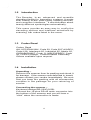
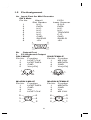
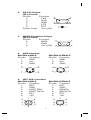
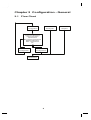
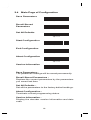
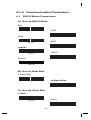
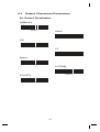
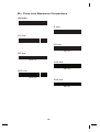
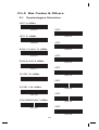
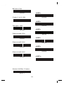
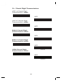
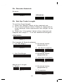
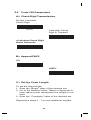
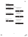
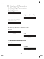
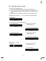
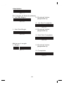
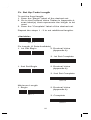
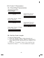
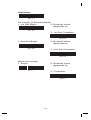
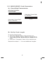
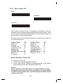
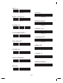
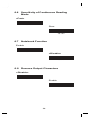
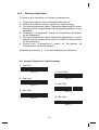
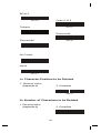
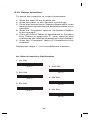
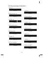
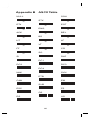
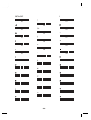
1
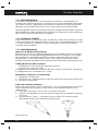
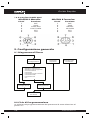
CCD Barcode Scanner Guida Rapida di Programmazione Programming Manual Cod. KR.L1 www.Kraun.it Guida Rapida Indice 1. Descrizione III 1.6.1 Uscita Tastiera PC 1.6.2 Uscita RS 232 1.6.3 Emulazione Uscita WAND 1.6.4 Interfaccia ADB 1.6.5 Interfaccia NEC 9801 V VI VI VI VII 1.1 Avviso 1.2 Introduzione 1.3 Lettura Codici 1.4 Installazione 1.5 Descrizione Funzioni Pin 1.6 Uscita III IV IV IV V V 2. Configurazione generale VII Programming Manual IX 2.1 Diagramma di Flusso 2.2 Ciclo di Programmazione 2.3 Impostazioni Predefinite VII VII VIII www.Kraun.it Guida Rapida 1. Descrizione 1.1 Avviso Aiutaci a proteggere lambiente, rispetta la normativa! Apparecchiature Elettriche ed Elettroniche da Dismettere Questo prodotto non deve essere smaltito come rifiuto urbano, ma deve essere oggetto di raccolta separata. Tutti i prodotti oggetto di raccolta separata sono identificati con il seguente simbolo: Se questo prodotto non è più utilizzato e se desiderate liberarvene, potete: Consegnare gratuitamente questa apparecchiatura ai centri di raccolta presso il Vs. comune di residenza. Consegnare gratuitamente questa apparecchiatura al Punto Vendita presso cui è stato effettuato lacquisto in occasione dellacquisto di una nuova apparecchiatura, a condizione che la stessa sia di tipo equivalente e con funzioni analoghe. Una modalità diversa di trattamento di questo prodotto, quando diviene inutilizzabile, può provocare danni enormi sullambiente e sulla salute umana per effetto del suo contenuto in piombo, mercurio, cadmio, cromo esavalente, bifenili polibromurati (pbb) e etile di difenile polibromurato (pbde). Sanzioni Le sanzioni sono stabilite dalla normativa nazionale; nello specifico il Decreto Legislativo n. 22 del 5 febbraio 1997 e successive modifiche, stabilisce nellArt 14 il Divieto di Abbandono. Le sanzioni previste dallArt 50 prevedono: [ ] chiunque [ ] abbandona o deposita rifiuti ovvero li immette nelle acque superficiali o sotterranee è punito con la sanzione amministrativa pecuniaria da lire duecentomila (Euro 103,29) a lire unmilioneduecentomila (Euro 619,75) [ ]. III www.Kraun.it Guida Rapida 1.2 Introduzione Il Lettore di codici è uno strumento avanzato e versatile per i sistemi di codifica a barre. Funziona con una varietà di tipologie di codici a barre, dispositivi di lettura e interfacce del computer. Identifica automaticamente circa venti differenti simbologie. Questa guida offre un modo facile di configurazione delle opzioni di decodifica e delle selezioni di interfaccia, attraverso la scansione dei codici a barre elencati di seguito. 1.3 Lettura Codici Codici di lettura: UPC/EAN/JAN, Code 39, Code 39 Full ASCII, Code 128, Interleave 25, Industrial 25, Matrix 25, CODABAR/NW7, Code 11, MSI/PLESSEY, Code 93, China Postage, Code 32/Prodotti Farmaceutici Italiani. 1.4 Installazione Apertura della confezione: Rimuovere il lettore dallimballaggio e controllare che sia integro. Se il prodotto risulta danneggiato durante il trasporto, si prega di contattare immediatamente il punto vendita dove è stato acquistato. In tal caso assicurarsi che nella confezione siano presenti tutti gli accessori forniti per poter effettuare la restituzione. Collegamento del Lettore: - Attraverso la porta della tastiera (PS/2) - Attraverso la porta USB Collegare il connettore maschio RS-45 a 10 pin al lettore. Avvenuto il collegamento, si sentirà un click. Installare il lettore al sistema: 1. Spegnere il sistema 2. Effettuare il collegamento ad una specifica porta del sistema 3. Avviare il sistema Cavo di Commutazione: Prima di rimuovere il cavo dal lettore, si raccomanda di accertarsi che il sistema sia spento e che non vi sia alimentazione nel dispositivo. 1. Cercare il piccolo foro-Pin in fondo allunità. 2. Usare una graffetta con curvatura regolare e inserire la punta nel foro. 3. Si sentirà un click. A questo punto sfilare il cavo tirando delicatamente la protezione di gomma. Serie SG/LG IV www.Kraun.it Guida Rapida Serie SD 1.5 Descrizione Funzioni Pin Ingresso per Mini Decoder DB 9 Maschio Pin N° 1 2 3 4 5 6 7 8 9 WAND/Slot Reader N.C. DATA N.C. N.C. N.C. N.C. GND SHIELD +5V CCD/Laser Scanner S.O.S. DATA N.C. N.C. TRIGGER P. E. GND SHIELD +5V 1.6 Uscita 1.6.1 Uscita Tastiera PC DIN 5 Maschio Pin. N° 1 2 4 5 V Funzione HOST CLK HOSTDATA GND Vcc(+5V) Pin. N° 1 2 4 5 Funzione KB CLK KBDATA GND Vcc(+5V) www.Kraun.it Guida Rapida MiniDIN 6 Maschio Pin N° 1 3 4 5 Funzione HOSTDATA GND Vcc HOST CLK MiniDIN 6 Femmina Pin N° 1 3 4 5 Funzione KB DATA GND Vcc KB CLK 1.6.2 Uscita RS-232 DB 9 Femmina Pin. N° 2 3 5 7 8 Alimentazione Funzione TXD RXD GND CTS RTS Vcc (+5V) 1.6.3 Emulazione Uscita WAND DB 9 Femmina Pin. N° 2 7 9 Funzione DATA GND Vcc (+5V) 1.6.4 Interfaccia ADB MiniDIN 4 Maschio Pin N° 1 3 4 VI Funzione ADB Vcc GND MiniDIN 4 Femmina Pin N° 1 3 4 Funzione ADB Vcc GND www.Kraun.it Guida Rapida 1.6.5 Interfaccia NEC 9801 MiniDIN 8 Maschio Pin N° 1 2 3 4 5 8 Funzione RST GND HOST RDY HOST DATA RTY +5V MiniDIN 8 Femmina Pin N° 1 2 3 4 5 8 Funzione RST GND KB RDY KB DATA RTY +5V 2. Configurazione generale 2.1 Diagramma di Flusso Inizia Configurazione Richiama Parametri Impostati Imposta tutto Predefinito Selezione Interfaccia Selezione Porta Ingresso Comunicazione Parametri Parametri Codici a Barre Parametri MSR Parametri Vari ecc. Annulla Configurazione Termina Configurazione Salva Parametri 2.2 Ciclo di Programmazione Lo schema di programmazione dei parametri è stato descritto al punto 2.1. VII www.Kraun.it Guida Rapida In sintesi, lutente deve: 1. Leggere (puntando il lettore sul codice corrispondente e premendo il pulsante) il codice Inizia Configurazione. 2. Leggere tutti i codici necessari per la programmazione personalizzata del prodotto. 3. Leggere il codice Termina Configurazione per terminare la programmazione. 4. Per salvare le impostazioni programmate, basta leggere il codice Salva Parametri. 5. Per tornare alle Impostazioni Iniziali (default), basta leggere il codice Imposta Tutto Predefinito. 2.3 Impostazioni Predefinite Le impostazioni predefinite sono indicate di seguito con i simboli < > e in grassetto. Si possono cambiare le impostazioni seguendo le procedure indicate nel manuale. Per salvare le impostazioni in modo permanente, bisogna leggere il codice Salva Parametri al paragrafo 2.4 del Programming Manual (pag. 10), altrimenti le impostazioni andranno perdute appena spento il lettore e tutti i parametri saranno riportati alla precedente impostazione. Leggendo il codice Imposta Tutto Predefinito, le impostazioni saranno riportate alla configurazione predefinita (default). Per tutte le altre programmazioni consultare il Programming Manual al paragrafo 2.4 (pag. 10). Attenzione!! Per la programmazione dei codici per prodotti farmaceutici italiani vedere il Programming Manual a pag. 26 Avvertenza Qualsiasi variazione fatta dallutilizzatore o da altri non autorizzati può compromettere la conformità e la sicurezza del prodotto di cui il produttore non si ritiene responsabile. VIII www.Kraun.it CCD Barcode Scanner Programming Manual Cod. KR.L1 Contents Chapter 1 1.1 1.2 1.3 1.4 1.5 Notice ....................................................... Introduction ........................................... Codes Read ........................................... Installation .............................................. Pin Assignment ...................................... Chapter 2 2.1 2.2 2.3 2.4 Description Configuration - General Flow Chart ............................................. Loop of Programming ........................... Factory Default Settings ........................ Main Page of Configuration ................... Chapter 3 3 4 4 4 6 8 9 9 10 Interface and Reading Mode Selection 3.1 Interface Selection ................................. 11 3.2 Memory Function .................................... 11 3.3 Reading Mode Selection ........................ 12 Chapter 4 4.1 4.2 4.3 4.4 4.5 Communication Parameters RS232 Mode Parameters ...................... Keyboard Wedge Mode Parameters..... Output Characters Parameters ............. Wand Emulation Mode Parameters...... OCIA Mode Parameters ........................ Chapter 5 13 15 17 19 20 Bar Codes & Others 5.1 Symbologies Selection ......................... 5.2 UPC/EAN/JAN Parameters ................... 5.3 Code 39 Parameters ............................. 5.4 Code 128 Parameters ........................... 5.5 Interleave 25 Parameters ...................... 5.6 Industrial 25 Parameters ....................... 5.7 Matrix 25 Parameters ............................ 5.8 CODABAR/NW7 Parameters ............... 5.9 Code 93 Parameters ............................. 5.10 Code 11 Parameters ............................. 5.11 MSI/PLESSEY Code Parameters ......... 1 21 24 26 28 30 32 34 36 38 40 42 5.12 BC412 Code Parameters ...................... 44 5.13 Code 2 of 6 Parameters ........................ 46 5.14 Telepen Parameters ............................... 48 Chapter 6 Miscellaneous Parameters 6.1 Language Selection .............................. 6.2 Bar Code ID .......................................... 6.3 Reading Level ........................................ 6.4 Accuracy ............................................... 6.5 Buzzer Beep Tone ................................. 6.6 Sensitivity of Continuous Reading Mode ... 6.7 Notebook Function ................................ 6.8 Reverse Output Characters .................. 6.9 Set Up Deletion ...................................... 6.10 Set Up Insertion ..................................... 6.11 Set Up IR Sensor ..................................... 50 52 55 55 55 56 56 56 57 60 63 Appendix A. B. C. Decimal Value Tables ............................ 63 ASCII Tables .......................................... 64 Function Key Tables .............................. 68 2 1.1 Notice T he manufacturer s hall not be liable for technical or editorial errors or omissions contained herein; nor for incidental or cons equential damages in connection with the furnishing, performance, or use of this publication. F C C A pproval T his device had been tes t in accorda nce with the procedure s given in ANS I C 63.4 (1992) and confirmed to complies with the limits for a C LAS S B digital pursua nt to part 15 of the F C C R ules . C E S tandards T he C E mark as s hown here indicate s this product had been tested in accordance with the procedure s given in E uropean C ouncil Directive 89/336/E E C and confirmed to comply with the E urope an S ta ndard E N55022:1994/ A1: 1995 C las s B , E N 55024/1998. T his ma rking s hown on the produc t or its lite ra ture , indic a te s tha t it s hould not be dis pos e d with othe r hous e holds wa s te s a t the e nd of its working life . To pre ve nt pos s ible ha rm to the e nvironme nt or huma n he a lthy from unc ontrolle d wa s te dis pos a l , ple a s e s epa ra te this from other types of wa s tes a nd recycle it re s pons ibly to promote the s us ta ina ble re us e of ma teria l res ources . H ous e hold us e rs s hould c onta c t e ithe r the re ta ile r whe re the y purc ha s e d this produc t, or the ir loc a l gove rnme nt offic e , for de ta ils of whe r a nd how the y can take this item fore environm entally s afe recycling. B us ines s us ers s hould contact their s upplier and check the terms a nd conditions of the purcha s e 3 1.2 Introduction The Decoder is an advanced and versatile decoding facility for barcoding systems .It works with variety of bar code types, reading devices, and computer interfaces. It discriminates about twenty different symbologies automatically. This menu provide an easy way to config the decoding options and interface selections by scanning bar codes listed in the menu. 1.3 Codes Read Codes Read ALL UPC/EAN/JAN , Code 39, Code 39 Full ASCII, Code 128, Interleave 25, Industrial 25, Matrix 25, CODABAR/NW7, Code 11, MSI/PLESSEY, Code 93, China Postage, Code32/Italian Pharmacy Others available upon request. 1.4 Installation Unpacking – Remove the scanner from its packing and check it for damage. If the scanner was defected in transit, please contact your vendor immediately. Be sure that you keep the packing with all accessories contains in the package for your returning of service. Connecting the scanner – Keyboard wedge/RS-232C/USB: Connect the 10-pins RS-45 male connector into the bottom of the scanner and you will hear a “click” when the connection is made. 4 Power supply for RS-232C scanner– There are 3 ways to supplying the power, use external +5V power supply, use optional power cable (KBDC) which taking the power from KB wedge or if the host supports +5V power from pin 9. Installing the scanner to the Host System – 1. Turn off the host system. 2. Connect the power if needed. 3. Connect to the proper port on the host system. 4. Turn on the host system. Switching cable – Before removing the cable from the scanner, it is recommended that the power on the host system is off and the power supply has been disconnected from unit. 1. Find the small “Pin-hole” on the bottom of the unit. 2. Use a bended regular paperclip and insert the tip into the hole. 3. You will head a “click”, then gentle on the strainrelief of the cable and it will slide out of the scanner. SG/LG Series SD Series 5 1.5 Pin Assignment A> Input Port for Mini Decoder DB 9 Male Pin No. Wand / CCD / Slot Reader Laser Scanner 1 N.C. S.O.S. 2 DATA DATA 3 N.C. N.C. 4 N.C. N.C. 5 N.C. TRIGGER 6 N.C. P. E. 7 GND GND 8 SHIELD SHIELD 9 +5V +5V 1 5 6 9 B> Output Port 1. PC Keyboard Output DIN 5 MALE DIN 5 FEMALE Pin No. Function Pin No. Function 1 HOST CLK 1 KB CLK 2 HOSTDATA 2 KBDATA 4 GND 4 GND 5 Vcc(+5V) 5 Vcc(+5V) 1 3 1 3 5 4 5 2 4 2 MiniDIN 6 MALE Pin No. Function 1 HOSTDATA 3 GND 4 Vcc 5 HOST CLK MiniDIN 6 FEMALE Pin No. Function 1 KBDATA 3 GND 4 Vcc 5 KB CLK 5 3 6 4 6 4 5 3 1 2 2 1 6 2. RS-232 Output DB 9 Female Pin No. Function 5 2 TXD 3 RXD 5 GND 9 7 CTS 8 RTS Power Lead Vcc (+5V) 3. WAND Emulation Output DB 9 Female Pin No. Function 2 DATA 7 GND 9 Vcc (+5V) 4. ADB Interface MiniDIN 4 MALE Pin No. Function 1 ADB 3 Vcc 4 GND 1 6 5 1 9 6 MiniDIN 4 FEMALE Pin No. Function 1 ADB 3 Vcc 4 GND 3 4 4 3 1 2 2 1 5. NEC 9801 Interface MiniDIN 8 MALE Pin No. Function 1 RST 2 GND 3 HOST RDY 4 HOST DATA 5 RTY 8 +5V 6 3 1 7 4 MiniDIN 8 FEMALE Pin No. Function 1 RST 2 GND 3 KB RDY 4 KB DATA 5 RTY 8 +5V 8 5 2 8 5 2 7 7 4 6 3 1 Chapter 2 Configuration - General 2.1 Flow Chart Start Configuration Recall Parameter Interface Selection Input Port Selection Communication Parameters Bar Codes Parameters MSR Parameters Misc .Parameters etc. Abort Configuration End Configuration Save Parameters 8 Set All Defaults 2.2 Loop of Programming The philosophy of programming parameters has been shown on the flow chart of 2.1. Basically user should 1. Scan Start of Configuration. 2. Scan all necessary labels for parameters that meet applications. 3. Scan End of Configuration to end the programming. 4. To permanently save the settings you programmed, just scan label for Save Parameters. 5. To go back to the Default Settings, just scan label for Set All Defaults. 2.3 Factory Default Settings The factory default settings are shown with < > and bold in the following sections. You can make your own settings by following the procedures in this manual. If you want to save the settings permanently, you should scan the label of "Save Parameters" in chapter 2.4, otherwise the settings will not be saved after the decoder power is off, and all settings will go back to previous settings. By scanning "Set All Default" label, the settings will go back to the factory default settings. 9 2.4 Main Page of Configuration Save Parameters %$ + / 0 Recall Stored Parameters %$ + / 1 Set All Defaults %$ + / 2 Start Configuration %$ + / 3 End Configuration %$ + / 4 Abort Configuration %$ + / 6 Version Information %$ + / 5 Save Parameters The parameter settings will be saved permanently. Recall Stored Parameters Replace the current parameters by the parameters you saved last time. Set All Defaults Set all the parameters to the factory default settings. Abort Configuration Terminate current programming status. Version Information Display the decoder version information and date code. 10 Chapter 3 Interface and Reading Mode Selection 3.1 Interface Selection <Keyboard Mode> %0 0 U0 RS232 Mode %0 0 U8 WAND Emulation %0 0 M2 OCIA Mode %0 0 M4 USB Mode %0 XO8 3.2 Memory Function <Enable> %0 XI 2 Disable %0 XI 0 11 3.3 Reading Mode Selection <Good Read OFF> %0 2 7 1 Trigger ON/OFF %0 2 7 0 Continuous/Trigger OFF %0 2 7 2 Testing %0 2 7 5 Continuous/Auto Power On %0 2 7 3 Flash %0 2 7 4 Flash/Auto Power On %0 2 7 6 Reserved1 %0 2 7 7 Reserved2 %0 9 F8 Reserved3 %0 9 F9 Reserved4 %0 9 FA Reserved5 %0 9 FB 12 Ch.4 Communication Parameters 4.1 RS232 Mode Parameters A> Set Up BAUD Rate 600 1200 %0 Y7 0 2400 %0 Y7 1 4800 %0 Y7 2 <9600> %0 Y7 3 19200 %0 Y7 7 38400 %0 Y7 4 %0 Y7 5 B> Set Up Data Bits 7 Data Bits <8 Data Bits> %0 Y8 0 %0 Y8 8 C> Set Up Stop Bits <1 Bit> 2 Bits %0 YO8 %0 YO0 13 D> Set Up Parity <None> Even %0 YN7 Odd %0 YN2 Mark %0 YN3 Space %0 YN1 %0 YN0 E> Handshaking RTS/CTS Enable <RTS/CTS Disable> %0 1 8 8 ACK/NAK Enable %0 1 8 0 <ACK/NAK Disable> %0 1 4 4 XON/XOFF Enable %0 1 4 0 <XON/XOFF Disable> %0 3 K4 %0 3 K0 14 4.2 Keyboard Wedge Mode Parameters A> Terminal Type <IBM PC/AT, PS/2> IBM PC/XT %0 ZF0 IBM PS/2 25, 30 %0 ZF1 NEC 9800 %0 ZF2 Apple Desktop Bus(ADB) %0 ZF3 IBM 5550 %0 ZF4 IBM 122 Key (1) %0 ZF5 IBM 102 Key %0 ZF6 IBM 122 Key (2) %0 ZF7 Reserved 1 %0 ZF8 Reserved 2 %0 ZF9 Reserved 3 %0 ZFA Reserved 4 %0 ZFB Reserved 5 %0 ZFC %0 ZFD 15 B> Upper/Lower Case <No Change> %0 3 3 0 Upper Case %0 3 3 1 Lower Case %0 3 3 2 C> Send Character by ALT Method Enable %0 3 O8 <Disable> %0 3 O0 D> Select Numerical Pad ON %0 1 K4 <OFF> %0 1 K0 16 4.3 Output Characters Parameters A> Select Terminator <CR+LF> %7 S2 + None %7 S7 + CR %7 S0 + LF %7 S1 + Space %7 S4 + HT(TAB) %7 S3 + STX-ETX %7 S5 + 17 B> Time-out Between Characters <0 ms> %0 0 7 0 5 ms %0 0 7 1 10 ms %0 0 7 2 25 ms %0 0 7 3 50 ms %0 0 7 4 100 ms %0 0 7 5 200 ms %0 0 7 6 300 ms %0 0 7 7 18 4.4 Wand Emulation Mode Parameters A> TTL Level Representation <Bar Equals High> %0 2 K4 Bar Equals Low %0 2 K0 B> Scan Speed Selection <Fast> %0 2 8 8 Slow %0 2 8 0 C> Output Format Selection <Output as Code 39> %0 2 O8 Output as Code 39 Full ASCII %0 2 O0 Output as Original Code Format %0 XK4 19 4.5 OCIA Mode Parameters <NCR 8 Bit Format> %0 2 J 0 NCR 9 Bit Format %0 2 J 1 Spectra-Physics %0 2 J 2 Nixdorf %0 2 J 3 20 Ch.5 Bar Codes & Others 5.1 Symbologies Selection UPC-A <ON> OFF %0 A4 4 UPC-E <ON> %0 A4 0 OFF %0 BO8 EAN-13/JAN-13 <ON> %0 BO0 OFF %0 A2 2 EAN-8/JAN-8 <ON> %0 A2 0 OFF %0 A1 1 CODE 39 <ON> %0 A1 0 OFF %0 EO8 CODE 128 <ON> %0 EO0 OFF %0 FO8 CODABAR/NW7 <ON> %0 FO0 OFF %0 J O8 %0 J O0 21 Interleave 25 <ON> OFF %0 GO8 Industrial 25 ON %0 GO0 <OFF> %0 HO8 Matrix 25 ON %0 HO0 <OFF> %0 I O8 CODE 93 ON %0 I O0 <OFF> %0 KO8 CODE 11 ON %0 KO0 <OFF> %0 L O8 China Postage ON %0 L O0 <OFF> %0 MO8 MSI/PLESSEY ON %0 MO0 <OFF> %0 NO8 %0 NO0 22 BC412 ON <OFF> %0 OO8 Code 2 of 6 ON %0 OO0 <OFF> %0 PO8 Telepen ON %0 PO0 <OFF> %0 TO8 Reserved4 ON %0 TO0 <OFF> %0 QO8 Reserved5 ON %0 QO0 <OFF> %0 RO8 %0 RO0 Reserved6 ON <OFF> %0 SO8 %0 SO0 Select All Bar Codes %1 A/ + 23 5.2 UPC/EAN/JAN Parameters A> Reading Type UPCA=EAN13 ON UPCA=EAN13<OFF> %0 AK4 ISBN Enable %0 AK0 ISBN <Disable> %0 B8 8 ISSN Enable %0 B8 0 ISSN <Disable> %0 B4 4 Decode with Supplement %0 B4 0 <Autodiscriminate Supplement> %0 1 O0 %0 1 O8 B> Supplementals Set Up <Not Transmit> Transmit 2 Code %0 B3 3 Transmit 5 Code %0 B3 1 Transmit 2&5 Code %0 B3 2 %0 B3 0 24 C> Check Digit Transmission UPC-A Check Digit Transmission <ON> OFF %0 AI 2 UPC-E Check Digit Transmission <ON> %0 AI 0 OFF %0 BI 2 EAN-8 Check Digit Transmission <ON> %0 BI 0 OFF %0 A8 8 EAN-13 Check Digit Transmission <ON> %0 A8 0 OFF %0 AH1 ISSN Check Digit Transmission <ON> %0 AH0 OFF %0 BK4 %0 BK0 25 5.3 Code 39 Parameters A> Type of Code <Standard> Full ASCII %0 EH1 %0 EH0 Italian Pharmacy/Code 32 <OFF> Italian Pharmacy/ Code 32 ON %0 E8 0 %0 E8 8 B> Check Digit Transmission <Do Not Calculate Check Digit> Calculate Check Digit & Transmit %0 EM2 Calculate Check Digit & Not Transmit %0 EM6 %0 EM4 C> Output Start/Stop Character Enable <Disable> %0 E4 4 %0 E4 0 26 D> Decode Asterisk Enable <Disable> %0 E2 2 %0 E2 0 E> Set Up Code Length To set the fixed length: 1. Scan the "Begin" label of the desired set. 2. Go to the Decimal Value Tables in Appendix A, scan label(s) that represents the length to be read. 3. Scan the "Complete" label of the desired set. Repeat the steps 1 - 3 to set additional lengths. <Variable> %4 E1 + Fix Length (2 Sets Available) 1. 1st Set Begin 2. Decimal Value (Appendix A) 3. 1st Set Complete %4 E0 0 %4 E0 1 1. 2nd Set Begin 2. Decimal Value (Appendix A) %4 E0 0 3. 2nd Set Complete %4 E0 2 Minimum Length 1. Begin 2. Decimal Value (Appendix A) 3. Complete %2 + - / %2 C0 + 27 5.4 Code 128 Parameters A> Check Digit Transmission Do Not Calculate Check Digit %0 FN1 Calculate Check Digit & Transmit %0 FN7 <Calculate Check Digit & Not Transmit> %0 FN5 B> Append FNC2 ON %0 F8 8 <OFF> %0 F8 0 C> Set Up Code Length To set the fixed length: 1. Scan the "Begin" label of the desired set. 2. Go to the Decimal Value Tables in Appendix A, scan label(s) that represents the length to be read. 3. Scan the "Complete" label of the desired set. Repeat the steps 1 - 3 to set additional lengths. 28 <Variable> %4 F1 + Fix Length (2 Sets Available) 1. 1st Set Begin 2. Decimal Value (Appendix A) %4 F0 0 3. 1st Set Complete %4 F0 1 1. 2nd Set Begin 2. Decimal Value (Appendix A) %4 F0 0 3. 2nd Set Complete %4 F0 2 Minimum Length 1. Begin 2. Decimal Value (Appendix A) %2 + - / 3. Complete %2 C1 + 29 5.5 Interleave 25 Parameters A> Check Digit Transmission <Do Not Calculate Check Digit> %0 GN3 Calculate Check Digit & Transmit %0 GN7 Calculate Check Digit & Not Transmit %0 GN5 B> Set Up Number of Character <Even> %0 G8 8 Odd %0 G8 0 C> Brazilian Banking Code <Disable> %0 G4 0 Enable %0 G4 4 30 D> Set Up Code Length To set the fixed length: 1. Scan the "Begin" label of the desired set. 2. Go to the Decimal Value Tables in Appendix A, scan label(s) that represents the length to be read. 3. Scan the "Complete" label of the desired set. Repeat the steps 1 - 3 to set additional lengths. <Variable> %4 G1 + Fix Length (2 Sets Available) 1. 1st Set Begin 2. Decimal Value (Appendix A) %4 G0 0 3. 1st Set Complete %4 G0 1 1. 2nd Set Begin 2. Decimal Value (Appendix A) %4 G0 0 3. 2nd Set Complete %4 G0 2 Minimum Length 1. Begin 2. Decimal Value (Appendix A) %2 + - / 3. Complete %2 C2 + 31 5.6 Industrial 25 Parameters A> Check Digit Transmission <Do Not Calculate Check Digit> %0 HN3 Calculate Check Digit & Transmit %0 HN7 Calculate Check Digit & Not Transmit %0 HN5 B> Set Up Code Length To set the fixed length: 1. Scan the "Begin" label of the desired set. 2. Go to the Decimal Value Tables in Appendix A, scan label(s) that represents the length to be read. 3. Scan the "Complete" label of the desired set. Repeat the steps 1 - 3 to set additional lengths. 32 <Variable> %4 H1 + Fix Length (2 Sets Available) 1. 1st Set Begin 2. Decimal Value (Appendix A) %4 H0 0 3. 1st Set Complete %4 H0 1 1. 2nd Set Begin 2. Decimal Value (Appendix A) %4 H0 0 3. 2nd Set Complete %4 H0 2 Minimum Length 1. Begin 2. Decimal Value (Appendix A) %2 + - / 3. Complete %2 C3 + 33 5.7 Matrix 25 Parameters A> Check Digit Transmission <Do Not Calculate Check Digit> %0 I N3 Calculate Check Digit & Transmit %0 I N7 Calculate Check Digit & Not Transmit %0 I N5 B> Set Up Code Length To set the fixed length: 1. Scan the "Begin" label of the desired set. 2. Go to the Decimal Value Tables in Appendix A, scan label(s) that represents the length to be read. 3. Scan the "Complete" label of the desired set. Repeat the steps 1 - 3 to set additional lengths. 34 <Variable> %4 I 1 + Fix Length (2 Sets Available) 1. 1st Set Begin 2. Decimal Value (Appendix A) %4 I 0 0 3. 1st Set Complete %4 I 0 1 1. 2nd Set Begin 2. Decimal Value (Appendix A) %4 I 0 0 3. 2nd Set Complete %4 I 0 2 Minimum Length 1. Begin 2. Decimal Value (Appendix A) %2 + - / 3. Complete %2 C4 + 35 5.8 CODABAR/NW7 Parameters A> Set Up Start/Stop Characters Upon Transmission ON <OFF> %0 J H1 %0 J H0 B> Transmission Type of Start/Stop <A/B/C/D> <Start> <A/B/C/D> <Stop> %0 4 VF A Start %0 4 FF A Stop %0 4 V1 B Start %0 4 F1 B Stop %0 4 V2 C Start %0 4 F2 C Stop %0 4 V4 D Start %0 4 F4 D Stop %0 4 V8 %0 4 F8 36 C> Set Up Code Length To set the fixed length: 1. Scan the "Begin" label of the desired set. 2. Go to the Decimal Value Tables in Appendix A, scan label(s) that represents the length to be read. 3. Scan the "Complete" label of the desired set. Repeat the steps 1 - 3 to set additional lengths. <Variable> %4 J 1 + Fix Length (2 Sets Available) 1. 1st Set Begin 2. Decimal Value (Appendix A) %4 J 0 0 3. 1st Set Complete %4 J 0 1 1. 2nd Set Begin 2. Decimal Value (Appendix A) %4 J 0 0 3. 2nd Set Complete %4 J 0 2 Minimum Length 1. Begin 2. Decimal Value (Appendix A) %2 + - / 3. Complete %2 C5 + 37 5.9 Code 93 Parameters A> Check Digit Transmission <Calculate Check 2 Digits & Not Transmit> %0 KN4 Do Not Calculate Check Digit %0 KN3 B> Set Up Code Length To set the fixed length: 1. Scan the "Begin" label of the desired set. 2. Go to the Decimal Value Tables in Appendix A, scan label(s) that represents the length to be read. 3. Scan the "Complete" label of the desired set. Repeat the steps 1 - 3 to set additional lengths. 38 <Variable> %4 K1 + Fix Length (2 Sets Available) 1. 1st Set Begin 2. Decimal Value (Appendix A) %4 K0 0 3. 1st Set Complete %4 K0 1 1. 2nd Set Begin 2. Decimal Value (Appendix A) %4 K0 0 3. 2nd Set Complete %4 K0 2 Minimum Length 1. Begin 2. Decimal Value (Appendix A) %2 + - / 3. Complete %2 C6 + 39 5.10 Code 11 Parameters A> Check Digit Transmission <Do Not Calculate Check Digit> Calculate Check 1 Digit & Transmit %0 L N3 %0 L N7 Calculate Check 1 Digit & Not Transmit Calculate Check 2 Digits & Transmit %0 L N5 %0 L N6 Calculate Check 2 Digits & Not Transmit %0 L N4 B> Set Up Code Length To set the fixed length: 1. Scan the "Begin" label of the desired set. 2. Go to the Decimal Value Tables in Appendix A, scan label(s) that represents the length to be read. 3. Scan the "Complete" label of the desired set. Repeat the steps 1 - 3 to set additional lengths. 40 <Variable> %4 L 1 + Fix Length (2 Sets Available) 1. 1st Set Begin 2. Decimal Value (Appendix A) %4 L 0 0 3. 1st Set Complete %4 L 0 1 1. 2nd Set Begin 2. Decimal Value (Appendix A) %4 L 0 0 3. 2nd Set Complete %4 L 0 2 Minimum Length 1. Begin 2. Decimal Value (Appendix A) %2 + - / 3. Complete %2 C7 + 41 5.11 MSI/PLESSEY Code Parameters A> Check Digit Transmission <Do Not Calculate Check Digit> Calculate Check Digit & Transmit %0 NN3 %0 NN7 Calculate Check Digit & Not Transmit %0 NN5 B> Set Up Code Length To set the fixed length: 1. Scan the "Begin" label of the desired set. 2. Go to the Decimal Value Tables in Appendix A, scan label(s) that represents the length to be read. 3. Scan the "Complete" label of the desired set. Repeat the steps 1 - 3 to set additional lengths. 42 <Variable> %4 N1 + Fix Length (2 Sets Available) 1. 1st Set Begin 2. Decimal Value (Appendix A) %4 N0 0 3. 1st Set Complete %4 N0 1 1. 2nd Set Begin 2. Decimal Value (Appendix A) %4 N0 0 3. 2nd Set Complete %4 N0 2 Minimum Length 1. Begin 2. Decimal Value (Appendix A) %2 + - / 3. Complete %2 C9 + 43 5.12 BC 412 Code Parameters A> Check Digit Transmission Do Not Calculate Check Digit <Calculate Check Digit & Transmit> %0 ON3 %0 ON7 Calculate Check Digit & Not Transmit %0 ON5 B> Set Up Code Length To set the fixed length: 1. Scan the "Begin" label of the desired set. 2. Go to the Decimal Value Tables in Appendix A, scan label(s) that represents the length to be read. 3. Scan the "Complete" label of the desired set. Repeat the steps 1 - 3 to set additional lengths. 44 <Variable> %4 O1 + Fix Length (2 Sets Available) 1. 1st Set Begin 2. Decimal Value (Appendix A) %4 O0 0 3. 1st Set Complete %4 O0 1 1. 2nd Set Begin 2. Decimal Value (Appendix A) %4 O0 0 3. 2nd Set Complete %4 O0 2 Minimum Length 1. Begin 2. Decimal Value (Appendix A) %2 + - / 3. Complete %2 CA+ 45 5.13 Code 2 of 6 Parameters A> Check Digit Transmission Do Not Calculate Check Digit <Calculate Check Digit & Transmit> %0 PN3 %0 PN7 Calculate Check Digit & Not Transmit %0 PN5 B> Set Up Code Length To set the fixed length: 1. Scan the "Begin" label of the desired set. 2. Go to the Decimal Value Tables in Appendix A, scan label(s) that represents the length to be read. 3. Scan the "Complete" label of the desired set. Repeat the steps 1 - 3 to set additional lengths. 46 <Variable> %4 P1 + Fix Length (2 Sets Available) 1. 1st Set Begin 2. Decimal Value (Appendix A) %4 P0 0 3. 1st Set Complete %4 P0 1 1. 2nd Set Begin 2. Decimal Value (Appendix A) %4 P0 0 3. 2nd Set Complete %4 P0 2 Minimum Length 1. Begin 2. Decimal Value (Appendix A) %2 +- / 3. Complete %2 CB+ 47 5.14 Telepen Parameters A> Type of Code <Telepen ASCII> Telepen Numeric %0 T8 0 %0 T8 8 B> Check Digit Transmission Do Not Calculate Check Digit Calculate Check Digit & Transmit %0 TN3 <Calculate Check Digit & Not Transmit> %0 TN7 %0 TN5 C> Set Up Code Length To set the fixed length: 1. Scan the "Begin" label of the desired set. 2. Go to the Decimal Value Tables in Appendix A, scan label(s) that represents the length to be read. 3. Scan the "Complete" label of the desired set. Repeat the steps 1 - 3 to set additional lengths. 48 <Variable> %4 T1 + Fix Length (2 Sets Available) 1. 1st Set Begin 2. Decimal Value (Appendix A) %4 T0 0 3. 1st Set Complete %4 T0 1 1. 2nd Set Begin 2. Decimal Value (Appendix A) %4 T0 0 3. 2nd Set Complete %4 T0 2 Minimum Length 1. Begin 2. Decimal Value (Appendix A) %2 +- / 3. Complete %2 CF+ 49 Ch.6 Miscellaneous Parameters 6.1 Language Selection <US English> %0 ZV0 UK English %0 ZV1 Italian %0 ZV2 Spanish %0 ZV3 French %0 ZV4 German %0 ZV5 Swedish %0 ZV6 Switzerland %0 ZV7 Hungarian %0 ZV8 Japanese %0 ZV9 50 Belgium %0 ZVA Portuguese %0 ZVB Denmark %0 ZVC Netherlands %0 ZVD Turkey %0 ZVE Reserved1 %0 ZVF 51 6.2 Bar Code ID ON <OFF> %0 0 H1 %0 0 H0 Default %9 1 3 + With this function ON, a leading character will be added to the output string while scanning code, user may refer to the following table to know what kind of bar code is being scanned. Please refer to the table below for matching code ID of codes read in. Code Type UPC-A EAN-8 CODE 39 Interleave 25 Matrix 25 CODE 93 China Postage BC412 Telepen ID A C E G I K M O T Code Type UPC-E EAN-13 CODE 128 Industrial 25 Codabar/NW7 CODE 11 MSI/PLESSEY Code 2 of 6 ID B D F H J L N P User Define Code ID To set the code ID: 1. Scan the symbologies label. 2. Go to the ASCII Tables in Appendix B, scan label that represents the desired code ID. Note: User define code ID will override default value. Program will not check the conflict. It is possible to have more than two symbologies which have same code ID. 52 UPC-A UPC-E %9 1 A+ EAN-13/JAN-13 %9 1 B+ EAN-8/JAN-8 %9 1 Y+ CODE 39 %9 1 Z+ CODE 128 %9 1 E+ CODABAR/NW7 %9 1 F+ Interleave 25 %9 1 J + Industrial 25 %9 1 G+ Matrix 25 %9 1 H+ CODE 93 %9 1 I + CODE 11 %9 1 K+ China Postage %9 1 L + MSI/PLESSEY %9 1 M+ BC412 %9 1 N+ %9 1 O+ 53 Code 2 of 6 %9 1 P+ Telepen %9 1 T+ Reserved4 %9 1 Q+ Reserved5 %9 1 R+ Reserved6 %9 1 S+ 54 6.3 Reading Level Bar Equals High <Bar Equals Low> %0 3 I 2 %0 3 I 0 6.4 Accuracy <1 Time> 2 Times %0 1 3 0 3 Times %0 1 3 1 4 Times %0 1 3 2 %0 1 3 3 6.5 Buzzer Beep Tone <High> Medium %0 1 J 3 Low %0 1 J 2 Off %0 1 J 1 %0 1 J 0 55 6.6 Sensitivity of Continuous Reading Mode <Fast> %0 3 8 8 Slow %0 3 8 0 6.7 Notebook Function Enable %0 3 4 4 <Disable> %0 3 4 0 6.8 Reverse Output Characters <Disable> %0 3 H0 Enable %0 3 H1 56 6.9 Setup Deletion To setup the deletion of output characters: 1. Scan the label of the desired set below. 2. Scan the label of the desired symbology. 3. Go to theDecimal Value Tables inAppendixA, scan label(s) that represents the desired position to be deleted. 4. Scan the "Complete" label of "Character Position to be Deleted". 5. Go to theDecimal Value Tables inAppendixA, scan label(s) that represents the number of characters to be deleted. 6. Scan the "Complete" label of "Number of Characters to be Deleted". Repeat the steps 1 - 6 to set additional deletion. A> Select Deletion Set Number 1. 1st Set 2. 2nd Set %8 0 0 + 3. 3rd Set %8 0 1 + 4. 4th Set %8 0 2 + 5. 5th Set %8 0 3 + 6. 6th Set %8 0 4 + %8 0 5 + 57 B> Symbologies Selection UPC-A UPC-E %8 1 A+ EAN-13/JAN-13 %8 1 B+ EAN-8/JAN-8 %8 1 Y+ CODE 39 %8 1 Z+ CODE 128 %8 1 E+ CODABAR/NW7 %8 1 F+ Interleave 25 %8 1 J + Industrial 25 %8 1 G+ Matrix 25 %8 1 H+ CODE 93 %8 1 I + CODE 11 %8 1 K+ China Postage %8 1 L + MSI/PLESSEY %8 1 M+ %8 1 N+ 58 BC412 Code 2 of 6 %8 1 O+ Telepen %8 1 P+ Resvered4 %8 1 T+ Resvered5 %8 1 Q+ %8 1 R+ All Codes %8 1 S+ None %8 1 4 + C> Character Position to be Deleted 1. Decimal Value (AppendixA) 2. Complete %8 2 0 + D> Number of Characters to be Deleted 1. Decimal Value (AppendixA) 2. Complete %8 3 0 + 59 6.10 Setup Insertion To setup the insertion of output characters: 1. Scan the label of the desired set. 2. Scan the label of the desired symbology. 3. Go to theDecimal Value Tables inAppendix A, scan label(s) that represents the desired position to be inserted. 4. Scan the "Complete" label of "Character Position to be Inserted". 5. Go to the ASCII Tables in Appendix B or Function Key Tables in Appendix C, scan label(s) that represents the desired characters to be inserted. 6. Scan the "Complete" label of "Characters to be Inserted". Repeat the steps 1 - 6 to set additional insertion. A> Select Insertion Set Number 1. 1st Set 2. 2nd Set %5 0 0 + 3. 3rd Set %5 0 1 + 4. 4th Set %5 0 2 + 5. 5th Set %5 0 3 + 6. 6th Set %5 0 4 + %5 0 5 + 60 B> Symbologies Selection UPC-A UPC-E %5 1 A+ EAN-13/JAN-13 %5 1 B+ EAN-8/JAN-8 %5 1 Y+ CODE 39 %5 1 Z+ CODE 128 %5 1 E+ CODABAR/NW7 %5 1 F+ Interleave 25 %5 1 J + Industrial 25 %5 1 G+ Matrix 25 %5 1 H+ CODE 93 %5 1 I + CODE 11 %5 1 K+ China Postage %5 1 L + MSI/PLESSEY %5 1 M+ %5 1 N+ 61 BC412 Code 2 of 6 %5 1 O+ Telepen %5 1 P+ Resvered4 %5 1 T+ Resvered5 %5 1 Q+ %5 1 R+ All Codes %5 1 S+ None %5 1 4 + C> Character Position to be Inserted 1. Decimal Value (AppendixA) 2. Complete %5 2 0 + D> Characters to be Inserted 1. ASCII Table (Appendix B) 2. Complete %5 3 0 + 62 6.11 Setup IR Sensor <Disable> %0 XH0 Enable %0 XH1 63 Appendix A Decimal Value Table 0 1 2 3 4 5 6 7 8 9 64 Appendix B ASCII Table NULL 00 SOH STX ETX 01 02 03 ENQ ACK 04 05 06 07 08 0A 0B 0D 0E 10 11 13 14 16 17 19 1A RS EM SUB ESC 1B SYN ETB CAN 18 DC3 DC4 NAK 15 DLE DC1 DC2 12 CR SO SI 0F LF VT FF 0C BEL BS HT 09 EOT FS GS 1C 1D 1E US 1F 65 SPACE 20 ! " 21 22 23 % 24 25 26 ( 27 28 29 + 2A 2B 2C . 2D 2E 2F 1 30 31 32 4 33 34 35 7 36 37 38 : 39 3A 3B = 3C 3D 3E 3F 66 40 B 41 42 43 E 44 45 46 H 47 48 49 K 4A 4B 4C N 4D 4E 4F Q 50 51 52 T 53 54 55 W 56 57 58 Z 59 5A 5B ] 5C 5D 5E 5F 67 60 b 61 62 63 e 64 65 66 h 67 68 69 k 6A 6B 6C n 6D 6E 6F q 70 71 72 t 73 74 75 w 76 77 78 z 79 7A 7B } 7C 7D 7E DEL 7F 68 Appendix C Function Key Table F1 F2 C0 C1 F3 C2 F4 F5 C3 C4 F6 C5 F7 F8 C6 C7 F9 C8 F10 F11 C9 CA F12 CB Insert Delete CC CD Home CE Page Up Page Down CF D0 End D1 Left Right D2 D3 Up D4 Down D5 69