1
UniVista User’s Guide
Release 1.0
Inside...
Navigating UniVista
Configuring UniVista parameters
Performing Device Management Tasks Using UniVista
Monitoring and Maintaining UniVista
Part No. 600-09000-001, Rev. 2
June 2008
Copyright
Beta Draft Confidential
Copyright © 2007 Proliphix, Inc. All Rights Reserved.
The following are trademarks of Proliphix, Inc.:
All other trademarks are the property of their respective owners.
This document contains information that is the property of Proliphix, Inc. This document may not be
copied, reproduced, reduced to any electronic medium or machine readable form, or otherwise
duplicated, and the information herein may not be used, disseminated or otherwise disclosed, except with
the prior written consent of Proliphix, Inc.
ii
UniVista User’s Guide, Release 1.0
Part No. 600-09000-001, Rev. 2
Beta Draft Confidential
Software License Agreement
License for Customer Use of Proliphix Software
IMPORTANT NOTICE -- READ CAREFULLY: This License For Customer Use of PROLIPHIX
Software ("LICENSE") is the agreement which governs use of the software of PROLIPHIX Corporation
and its subsidiaries ("PROLIPHIX") downloadable herefrom, including computer software and
associated printed materials ("SOFTWARE"). By downloading, installing, copying, or otherwise using
the SOFTWARE, you agree to be bound by the terms of this LICENSE. If you do not agree to the terms
of this LICENSE, do not download or run the SOFTWARE.
RECITALS
Use of PROLIPHIX's products requires three elements: the SOFTWARE, a PROLIPHIX Thermostat,
and a personal computer. The SOFTWARE is protected by copyright laws and international copyright
treaties, as well as other intellectual property laws and treaties. The SOFTWARE is not sold, and instead
is only licensed for use, strictly in accordance with this document. The hardware is protected by various
patents, and is sold, but this LICENSE does not cover that sale, since it may not necessarily be sold as a
package with the SOFTWARE. This LICENSE sets forth the terms and conditions of the SOFTWARE
LICENSE only.
DEFINITIONS
Customer. Customer means the entity or individual that downloads the SOFTWARE.
GRANT OF
LICENSE
Rights and Limitations of Grant. PROLIPHIX hereby grants Customer the following non-exclusive,
non-transferable right to use the SOFTWARE, with the following limitations:
Rights. Customer may install and use one copy of the SOFTWARE on a single computer, and except for
making one back-up copy of the Software, may not otherwise copy the SOFTWARE. This LICENSE of
SOFTWARE may be used concurrently on different computers.
Limitations.
No Reverse Engineering. Customer may not reverse engineer, decompile, or disassemble the
SOFTWARE, nor attempt in any other manner to obtain the source code.
No Separation of Components. The SOFTWARE is licensed as a single product. Its component parts may
not be separated for use on more than one computer, nor otherwise used separately from the other parts.
No Rental. Customer may not rent or lease the SOFTWARE to someone else.
TERMINATION
This LICENSE will automatically terminate if Customer fails to comply with any of the terms and
conditions hereof. In such event, Customer must destroy all copies of the SOFTWARE and all of its
component parts.
Defensive Suspension. If Customer commences or participates in any legal proceeding against
PROLIPHIX, then PROLIPHIX may, in its sole discretion, suspend or terminate all license grants and
any other rights provided under this LICENSE during the pendency of such legal proceedings.
COPYRIGHT
All title and copyrights in and to the SOFTWARE (including but not limited to all images, photographs,
animations, video, audio, music, text, and other information incorporated into the SOFTWARE), the
accompanying printed materials, and any copies of the SOFTWARE, are owned by PROLIPHIX, or its
suppliers. The SOFTWARE is protected by copyright laws and international treaty provisions.
Accordingly, Customer is required to treat the SOFTWARE like any other copyrighted material, except
as otherwise allowed pursuant to this LICENSE and that it may make one copy of the SOFTWARE
solely for backup or archive purposes.
APPLICABLE
LAW
This LICENSE shall be deemed to have been made in, and shall be construed pursuant to, the laws of the
Commonwealth of Massachusetts. The United Nations Convention on Contracts for the International Sale
of Goods is specifically disclaimed.
UniVista User’s Guide
Part No. 600-09000-001, Rev. 2
iii
Software License Agreement
DISCLAIMER OF
WARRANTIES
AND
LIMITATION ON
LIABILITY
Beta Draft Confidential
No Warranties. TO THE MAXIMUM EXTENT PERMITTED BY APPLICABLE LAW, THE
SOFTWARE IS PROVIDED "AS IS" AND PROLIPHIX AND ITS SUPPLIERS DISCLAIM ALL
WARRANTIES, EITHER EXPRESS OR IMPLIED, INCLUDING, BUT NOT LIMITED TO,
IMPLIED WARRANTIES OF MERCHANTABILITY AND FITNESS FOR A PARTICULAR
PURPOSE.
No Liability for Consequential Damages. TO THE MAXIMUM EXTENT PERMITTED BY
APPLICABLE LAW, IN NO EVENT SHALL PROLIPHIX OR ITS SUPPLIERS BE LIABLE FOR
ANY SPECIAL, INCIDENTAL, INDIRECT, OR CONSEQUENTIAL DAMAGES WHATSOEVER
(INCLUDING, WITHOUT LIMITATION, DAMAGES FOR LOSS OF BUSINESS PROFITS,
BUSINESS INTERRUPTION, LOSS OF BUSINESS INFORMATION, OR ANY OTHER
PECUNIARY LOSS) ARISING OUT OF THE USE OF OR INABILITY TO USE THE SOFTWARE,
EVEN IF PROLIPHIX HAS BEEN ADVISED OF THE POSSIBILITY OF SUCH DAMAGES.
OTHER
iv
If any provision of this LICENSE is inconsistent with, or cannot be fully enforced under, the law, such
provision will be construed as limited to the extent necessary to be consistent with and fully enforceable
under the law. This LICENSE is the final, complete and exclusive agreement between the parties relating
to the subject matter hereof, and supersedes all prior or contemporaneous understandings and agreements
relating to such subject matter, whether oral or written. This LICENSE may only be modified in writing
signed by an authorized officer of PROLIPHIX. Customer agrees that it will not ship, transfer or export
the SOFTWARE into any country, or use the SOFTWARE in any manner, prohibited by the United
States Bureau of Export Administration or any export laws, restrictions or regulations.
UniVista User’s Guide
Part No. 600-09000-001, Rev. 2
Beta Draft Confidential
Contents
Preface
Chapter 1
Understanding and Installing UniVista
Overview 1-2
Operating Requirements 1-4
Hardware Requirements 1-4
Software Requirements 1-4
Network Requirements 1-4
UniVista Time Synchronization 1-5
Licensing 1-6
Chapter 2
Navigating UniVista
Accessing UniVista 2-2
Understanding the Menu Bar 2-4
Understanding the Management Tabs 2-4
System Summary Tab 2-5
Administration Tab 2-6
Understanding the Folder Tree 2-7
Understanding Modes of Operation Using Single Device Selection and Group Device(s)
Selection 2-9
Single Device Selection Mode 2-9
Group Device(s) Selection Mode 2-10
Performing Bulk or Multiple Configuration Changes 2-11
Summary of Selecting a Single Device or Mulitple Devices 2-12
Understanding Account Permission Levels 2-13
Chapter 3
Configuring UniVista Parameters
Configuring System Setup Information 3-3
Adding a Folder 3-5
Adding a Device 3-6
Example 1 3-8
Example 2 3-10
Example 3 3-12
UniVista User’s Guide
Part No. 600-09000-001, Rev. 2
v
Contents
Chapter 4
Beta Draft Confidential
Performing Device Management Tasks Using UniVista
Accessing the Management Functions 4-2
Status & Control Page 4-4
General Settings Page 4-10
Alarms Settings Page 4-14
Schedules Settings Page 4-18
Thermostat Scheduling using the Calendar Page 4-19
Day Class Schedule 4-20
Default Weekly Schedule 4-21
Calendar View 4-22
Special Day Selection Example 1 4-23
Special Day Selection Example 2 4-24
Thermostat Scheduling using Special Days 4-24
Network Settings Page 4-25
HVAC Settings Page 4-30
Sensor Settings Page 4-42
Remote Access Page 4-45
Remote Server Configuration 4-45
Installer Info Page 4-49
Usage Counters Page 4-50
Chapter 5
Maintaining and Monitoring UniVista
Managing Devices 5-2
Viewing a Device’s Information 5-2
Editing a Device 5-3
Deleting a Device 5-4
Managing Folders 5-5
Editing a Folder 5-5
Deleting a Folder 5-6
Managing Accounts 5-7
Adding Accounts 5-8
Associating Accounts and Folders 5-10
Editing Accounts 5-11
Deleting Accounts 5-12
Managing Groups 5-13
Creating a Group 5-15
Loading a Group 5-16
Adding Devices to and Removing Devices from a Group 5-17
Editing a Group 5-19
Unloading a Group 5-19
Selecting and De-Selecting all Groups 5-19
Deleting a Group 5-20
Using Configuration Files 5-21
Creating a Configuration File 5-23
Saving a Configuration File 5-24
Applying a Configuration File 5-25
Editing a Configuration File 5-26
Copying a Configuration File 5-27
Deleting a Configuration File 5-27
vi
UniVista User’s Guide
Part No. 600-09000-001, Rev. 2
Beta Draft Confidential
Contents
Viewing Action and Alarm Information 5-28
Viewing log files for an Individual Device 5-28
Displaying the Callhome Log 5-29
Displaying the Action Log 5-30
Displaying the Alarm Log 5-31
Viewing log files for the Entire Network 5-33
Action Logs 5-33
Alarm Logs 5-34
Viewing all Alarms in the Folder Tree 5-34
Managing the License Subscription 5-35
Viewing the License Subscription 5-35
Updating the License Subscription 5-36
Viewing System Information 5-36
Logging Out of UniVista 5-37
Appendix A
Configuration Worksheet
UniVista User’s Guide
Part No. 600-09000-001, Rev. 2
vii
Contents
viii
Beta Draft Confidential
UniVista User’s Guide
Part No. 600-09000-001, Rev. 2
Beta Draft Confidential
Figures
List of Figures
Figure 1-1
Figure 1-2
Figure 2-1
Figure 2-2
Figure 2-3
Figure 2-4
Figure 2-5
Figure 2-6
Figure 2-7
Figure 2-8
Figure 2-9
Figure 3-1
Figure 3-2
Figure 3-3
Figure 3-4
Figure 3-5
Figure 3-6
Figure 3-7
Figure 3-8
Figure 3-9
Figure 3-10
Figure 3-11
Figure 4-1
Figure 4-2
Figure 4-3
Figure 4-4
Figure 4-5
Figure 4-6
Figure 4-7
Figure 4-8
Figure 4-9
Figure 4-10
Figure 4-11
Figure 4-12
Figure 4-13
Figure 4-14
Figure 4-15
Figure 4-16
Figure 4-17
Figure 4-18
Figure 4-19
Figure 4-20
Figure 4-21
Figure 5-1
Figure 5-2
Figure 5-3
Figure 5-4
Figure 5-5
UniVista User’s Guide
Part No. 600-09000-001, Rev. 2
Beta License 1-6
Trial License 1-6
Download and/or Start UniVista Window 2-2
UniVista Login Window 2-2
UniVista Main Window 2-3
Menu Bar 2-4
Management Functions 2-4
Folder Tree 2-7
Single Device Selection Mode Example 2-9
Group Device(s) Selection Mode Example 2-10
Bulk Configuration Changes Example 2-11
Adding a Device Overview 3-2
System Setup Window 3-3
Add Folder Window 3-5
Add Device Window 3-6
Example 1 - Simple Network 3-8
Example 1 - Add Device Window 3-9
Example 2 - Single Firewall 3-10
Example 2 - Add Device Window 3-11
Example 3 - Double Firewall 3-12
Example 3 - Add Device Window #1 3-13
Example 3 - Add Device Window #2 3-14
Function Frame 4-2
Status and Control Page 4-4
General Settings Page 4-10
Alarm Settings Page 4-14
Schedules Settings - Calendar Page 4-18
Special Days Page 4-18
Day Class Scheduling 4-19
Day Class Schedules Table 4-20
Default Weekly Schedule Table 4-21
Calendar View Window 4-22
Special Day Selection Window 4-22
Special Day Selection - Example 1 Page 4-23
Special Day Selection - Example 2 Page 4-24
Special Days - Newly Added Schedule 4-24
Network Settings Page 4-25
HVAC Settings Page - Fuel Burner 4-30
HVAC Settings Page - Heat Pump 4-31
Sensor Settings Page 4-42
Remote Access Page 4-45
Installer Info Page 4-49
Usage Counters Page 4-50
Device Info Window 5-2
Edit Device Window 5-3
Confirm Device Delete Window 5-4
Edit Folder Window 5-5
Confirm Device Delete Window 5-6
ix
Beta Draft Confidential
Figures
Figure 5-6
Figure 5-7
Figure 5-8
Figure 5-9
Figure 5-10
Figure 5-11
Figure 5-12
Figure 5-13
Figure 5-14
Figure 5-15
Figure 5-16
Figure 5-17
Figure 5-18
Figure 5-19
Figure 5-20
Figure 5-21
Figure 5-22
Figure 5-23
Figure 5-24
Figure 5-25
Figure 5-26
Figure 5-27
Figure 5-28
Figure 5-29
Figure 5-30
Figure 5-31
Figure 5-32
Figure 5-33
x
Administration Accounts Frame 5-7
Add Account Window 5-8
Edit Account Dialog Window 5-11
Confirm Account Dialog Window 5-12
Load Group Window 5-13
Selected Configuration File 5-14
Add Group Window 5-15
Load Group Window 5-16
Load Group Display 5-16
Save Group Window 5-17
Newly Added Device Window 5-18
Edit Group Window 5-19
Delete Group Window 5-20
Confirm Group Delete Window 5-20
Configurations Folder 5-22
Add Configuration Window 5-23
Configurations - Function Frame 5-24
Edit Configurations Window 5-26
Copy Configuration Window 5-27
Confirm Configuration Delete Window 5-27
Callhome Log 5-29
Action Log 5-30
Alarm Log 5-31
Action Logs - System-Wide Window 5-33
Alarm Logs - System-Wide 5-34
License Description 5-35
System Summary Window 5-36
Logout - Alert Window 5-37
UniVista User’s Guide
Part No. 600-09000-001, Rev. 2
Beta Draft Confidential
Tables
List of Tables
Table 2-1
Table 2-2
Table 3-1
Table 3-2
Table 4-1
Table 4-2
Table 4-3
Table 4-4
Table 4-5
Table 4-6
Table 4-7
Table 4-8
Table 4-9
Table 4-10
Table 5-1
Table 5-2
Table 5-3
Table 5-4
Table 5-5
Table 5-6
UniVista User’s Guide
Part No. 600-09000-001, Rev. 2
System Summary Tab Icons 2-5
Administration Tab Icons 2-6
Administrations - System Setup Fields 3-4
Add Device Fields 3-7
Status and Control Field Descriptions 4-5
General Settings Field Descriptions 4-11
Alarm Settings Field Descriptions 4-14
Day Class Schedule Field Descriptions 4-20
Default Weekly Schedule Field Descriptions 4-21
Network Settings Field Descriptions 4-26
HVAC Settings Field Descriptions 4-32
Sensor Settings Field Descriptions 4-43
Remote Access Page Field Descriptions 4-46
Usage Counters Page Field Descriptions 4-51
Add Account Dialog Box Fields 5-8
Callhome Log Fields 5-29
Action Log Fields 5-31
Alarm Log Fields 5-32
Action Log - System-Wide Fields 5-33
Alarm Log - System-Wide Fields 5-34
xi
Tables
xii
Beta Draft Confidential
UniVista User’s Guide
Part No. 600-09000-001, Rev. 2
Beta Draft Confidential
Preface
The UniVista User’s Guide describes how to manage Proliphix network devices
remotely using UniVista, the Proliphix Device Management Software.
Audience
This guide is intended for managers and/or facilities managers or those responsible for
managing multiple thermostats remotely in small or medium size buildings, multiple
buildings, or corporate environments.
As a reader of this guide you should be familiar with the use of an Internet browser
(for example Internet Explorer or Mozilla) and a working knowledge on general data
networking principles. You should have prior experience with establishing a local area
network in either a home or office. You should understand the basic principles of
connecting patch panels and switches as well as configuring features on a firewall
router.
Be sure to read the Software Release Notes (SRN) that accompanies this product. The
SRN contains the most current product information and requirements.
UniVista User’s Guide, Release 1.0
Part No. 600-09000-001, Rev. 2
xiii
Beta Draft Confidential
Preface
Proliphix Documentation Library
The following documentation is available for Proliphix products. Software Release
Notes ship with each product. For ordering information, see Technical Publications
(page -xvi).
Proliphix Product
Title
Audience
NT10e, NT20e,
NT100e/h, NT120e/h,
NT130e/h, NT150e/h,
and NT160e/h
Proliphix Thermostat Installation Guide
For customers who want to install the Basic and
Professional series thermostat.
EPA 20 and EPA 60
Proliphix Ethernet Power Adapter Installation
Guide
For customers who want to install the EPA-20 or
EPA-60 Ethernet Power Adapter.
NT10e, NT20e,
NT100e/h, NT120e/h,
NT130e/h, NT150e/h,
and NT160e/h
Proliphix Remote Management Setup and
User’s Guide
For customers who want to remotely manage
their thermostats through secure authentication at
the Proliphix website.
TM220e/h and
TM250e/h
Thermal Management Series Network
Thermostat Configuration Guide
(TM220e/h and TM250e/h)
For customers who want to access and control
their Proliphix Thermal Management series
thermostat through either the Thermostat Device
Interface or more specifically through the
browser-based Thermostat Management
Interface (TMI).
NT100e/h, NT120e/h,
NT130e/h, NT150e/h,
and NT160e/h
Professional Series Network Thermostat
Configuration Guide
(NT100e/h, NT120e/h, NT130e/h, NT150e/h,
and NT160e/h)
For customers who want to access and control
their Proliphix Professional series thermostat
through either the Thermostat Device Interface or
more specifically through the browser-based
Thermostat Management Interface (TMI).
NT10e and NT20e
Basic Series Network Thermostat
Configuration Guide
(NT10e and NT20e)
For customers who want to access and control
their Proliphix Basic series thermostat through
either the Thermostat Device Interface or more
specifically through the browser-based
Thermostat Management Interface (TMI).
NT10e, NT20e,
NT100e/h, NT120e/h,
NT130e/h, NT150e/h,
NT160e/h TM220e/h,
and TM250e/h
UniVista Installation Guide
For customers who want to install UniVista.
NT10e, NT20e,
NT100e/h, NT120e/h,
NT130e/h, NT150e/h,
NT160e/h TM220e/h,
and TM250e/h
UniVista User’s Guide
For customers who want to manage their
Proliphix devices remotely using UniVista.
xiv
UniVista User’s Guide, Release 1.0
Part No. 600-09000-001, Rev. 2
Beta Draft Confidential
Preface
Conventions
This guide uses the following conventions, when applicable:
Description
Convention and Example
Commands or keywords, file or path names
Boldface font
Variable parameters for which you supply values
<courier italics>
Options and arguments for which you supply values
[]
Information that the user must enter
Courier Bold font
Screen messages or system output
Courier Regular font
Selecting a menu item
Menu => Option
Book titles, new terms, and emphasized text
Italics
Additional information that may apply to the subject text.
Note
Proceed carefully to avoid possible equipment damage or data loss.
Caution
Proceed carefully to avoid possible personal injury.
Warning
Provide helpful suggestions.
Tip
UniVista User’s Guide, Release 1.0
Part No. 600-09000-001, Rev. 2
xv
Beta Draft Confidential
Preface
Technical Publications
Customers can obtain product documentation on our web site at
http://www.proliphix.com/Documenation.aspx.
Note
Documentation is available for currently supported product releases.
Documentation is available in Adobe PDF format. You can view PDFs online using
the Adobe Reader ® 6.0 or later. To download the latest version of the Adobe
Reader software from the Adobe web site, click
http://www.adobe.com/products/acrobat/readstep2.html.
Technical Support
Proliphix Technical Support provides technical support between the hours of 9:00 AM
and 5:00 PM Eastern Time, Monday through Friday. Extended 7/24 contracts are
available.
When contacting Proliphix Technical Support, please have the following information
available:
Product model and serial number
Type of heating/cooling system (for example, gas, oil, or electric; warm air, hot
water, heat pump, steam or gravity)
Location and number of wires attached to the Proliphix thermostat
To contact Proliphix Technical Support:
Proliphix, Inc.
www.proliphix.com
3 Lan Drive
Westford, MA 01886
E-mail: [email protected]
Telephone support
1-866-IPLIVING
Fax: Attention Proliphix Technical Support
1-978-692-3378
xvi
UniVista User’s Guide, Release 1.0
Part No. 600-09000-001, Rev. 2
Beta Draft Confidential
Preface
Proliphix Welcomes Your Comments
You can mail, email, or fax your comments. Please include the document part number
in the subject line of your email or fax message.
E-mail: [email protected]
Fax: Attention Technical Publications
978-692-3378
Proliphix, Inc.
Technical Publications
3 Lan Drive
Westford, MA 01886
UniVista User’s Guide, Release 1.0
Part No. 600-09000-001, Rev. 2
xvii
Preface
xviii
Beta Draft Confidential
UniVista User’s Guide, Release 1.0
Part No. 600-09000-001, Rev. 2
Beta Draft Confidential
Chapter
1
Understanding and Installing UniVista
This chapter provides an overview of UniVista. It also describes the hardware,
software, and network operating requirements, as well as the different types of
licensing UniVista supports.
Specifically, it describes the following sections:
Overview (page 1-2)
Operating Requirements (page 1-4)
UniVista Time Synchronization (page 1-5)
Licensing (page 1-6)
UniVista User’s Guide
Part No. 600-09000-001, Rev. 2
1-1
Beta Draft Confidential
CHAPTER 1: Understanding and Installing UniVista
Overview
UniVista is a java-based application that enables you to organize, configure, and
manage multiple devices (thermostats) at the same time in order to streamline your
day-to-day operations. Using UniVista, you can manage a number of devices installed
throughout a large geographic area from one main location.
UniVista provides a clean and simple graphical interface used to manage a few or
hundreds of Proliphix Network Thermostats that may be located across multiple
geographically separated facilities. Paired with Proliphix Network Thermostats,
UniVista offers a complete HVAC monitoring and control solution with
unprecedented ease-of-use for HVAC management in any small to medium-sized
facility.
The graphical client interface is communicated to the user’s desktop or laptop
computer after an authenticated user login. The UniVista client interface organizes all
enterprise Network Thermostats neatly in a familiar Windows-style folder hierarchy
and clearly displays the most pertinent thermostat status along with any alarm or alert
notifications. The thermostat status is periodically updated automatically making total
enterprise thermostat monitoring easy and efficient.
Function Frames are used to control a single or group of Network Thermostats and are
purposely similar to the respective Network Thermostat Web pages. Function Frame
parameters are easily modified through convenient drop-down menus, which provide
for unprecedented ease of schedule programming and HVAC settings changes. For
more information on Function Frames, see Accessing the Management Functions
(page 4-2).
Configuration files (or Templates) enable you to save settings that you wish to store
for application to other groups of Network Thermostats. You can save an unlimited
number of Schedule Configurations or HVAC Configurations. For more information
on Configuration files, see Using Configuration Files (page 5-21).
User access to UniVista may be limited by the Administrator to only those devices
that are within the responsibility of the user. Control of any devices outside the user’s
account privileges are restricted. For more information about user access, see
Understanding Account Permission Levels (page 2-13).
1-2
UniVista User’s Guide
Part No. 600-09000-001, Rev. 2
Beta Draft Confidential
Overview
The following is a list of UniVista features and benefits:
Features
–
Hierarchical Device Organization
–
Single or Group Device Control
–
Functional or Geographical
–
Thermostat Grouping
–
Immediate Visual Alarm Notification
–
Continual Device Status Monitoring
–
Stored Schedule Configurations
–
Stored HVAC Settings Configurations
–
Hierarchical User Account Management
–
Familiar Functional Thermostat Control
–
E-mail or Text Message Fault Reporting
–
Standards Based TCP/IP Communications
Benefits
–
Leverages both the enterprise data network and the Internet
–
Administer common changes to multiple thermostats
–
Save predefined common or specific device settings
–
Restrict user access privileges
–
Save groups of selected thermostats
UniVista User’s Guide
Part No. 600-09000-001, Rev. 2
1-3
Beta Draft Confidential
CHAPTER 1: Understanding and Installing UniVista
Operating Requirements
This section lists the hardware, software, and network requirements for accessing
UniVista.
Note
Prior to configuring and managing devices, you must know the IP address for each
device. Use Appendix A, Configuration Worksheet to record the information.
Hardware Requirements
To run UniVista, the following minimum hardware is required:
Microsoft Windows XP Professional, Service Pack 2
Windows Server 2003 R2 (32 bit version only, 64 bit version not supported)
1 GB of RAM, 200 MB of hard disk space, Intel Pentium 4/AMD equivalent or
greater processor
Proliphix recommends a minimum of a 19” landscape monitor.
Note
Software Requirements
To log into UniVista remotely, you must have the following:
Note
Internet Explorer 6.x or Firefox 1.x.
Java Runtime Environment (JRE) version 1.5.0_12 or 1.5.0_14
The JRE is automatically installed by Java Web Start when the client is invoked. If
you are behind a firewall and unable to invoke access, the JRE has been included
on the UniVista Installation CD in the Client directory. For more information,
contact Technical Support (page -xvi).
Network Requirements
To support UniVista, your network must meet the following requirements:
1-4
If the server is behind a firewall, you must have a port forward configured on the
HTTP port and the SSL port back to UniVista.
A DNS name for the server (see step 2 on page 2-2).
UniVista User’s Guide
Part No. 600-09000-001, Rev. 2
Beta Draft Confidential
UniVista Time Synchronization
UniVista Time Synchronization
The UniVista Server synchronizes the time on all of the thermostats based off the
local PC’s time setting.
The server should be basing its time off an NTP service to insure proper time which in
turn is broadcast out to the thermostats.
Every night at midnight, the UniVista Server polls all the thermostats and time
synchronizes them based on their current time zone settings.
UniVista User’s Guide
Part No. 600-09000-001, Rev. 2
1-5
Beta Draft Confidential
CHAPTER 1: Understanding and Installing UniVista
Licensing
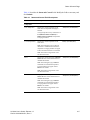
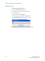
UniVista supports three types of licensing: Beta, Trial, and Server. A Beta license
expires on a specific date. When you have a Beta license then each time you log into
UniVista a dialog similar to the one show below appears indicating when your license
expires. See Figure 1-1.
Figure 1-1
Beta License
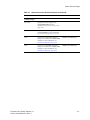
A Trial license expires 30 days from the time UniVista was installed. When you have
a Trial license then each time you log into UniVista a dialog similar to the one shown
below appears indicating when the license is due to expire. See Figure 1-2.
Figure 1-2
Trial License
A Trial license allows for up to 100 devices to be configured using UniVista and 5
concurrent users. For example, if 2 users are logged in as the admin user then this
counts as 2 users.
A Server license does not expire, therefore no dialog appears.
Note
Once a license has expired, a dialog appears indicating the license has expired. You
are able to access UniVista, however you are not able to manage the folder tree or
configure devices using the Function Frame until the license subscription is updated.
To update the license subscription, see Updating the License Subscription (page
5-36).
1-6
UniVista User’s Guide
Part No. 600-09000-001, Rev. 2
Beta Draft Confidential
Chapter
2
Navigating UniVista
This chapter describes how to navigate UniVista and understand account permissions.
Specifically, it describes the following sections:
Accessing UniVista (page 2-2)
Understanding the Menu Bar (page 2-4)
Understanding the Management Tabs (page 2-4)
Understanding the Folder Tree (page 2-7)
Summary of Selecting a Single Device or Mulitple Devices (page 2-12)
Understanding Account Permission Levels (page 2-13)
UniVista User’s Guide
Part No. 600-09000-001, Rev. 2
2-1
CHAPTER 2: Navigating UniVista
Beta Draft Confidential
Accessing UniVista
To access UniVista:
1
Open a browser window.
2
Enter http://<server IP address> in the browser window.
The Download and/or Start UniVista window appears. See Figure 2-1.
Figure 2-1
3
Note
Download and/or Start UniVista Window
Click Download and/or Start UniVista.
If the Warning - Security window appears, click Always trust content from this
publisher then click Run to verify this window does not appear again.
The UniVista login window appears. See Figure 2-2.
Figure 2-2
2-2
UniVista Login Window
UniVista User’s Guide
Part No. 600-09000-001, Rev. 2
Beta Draft Confidential
4
Accessing UniVista
Enter admin in both the Username and Password fields.
After you log in as the Administrator then you can modify the password.
Note
5
Click Login.
The UniVista main window appears. See Figure 2-3.
Figure 2-3
UniVista Main Window
The Application Information window also appears and displays the license
information specific to the client. For more information, see Licensing (page 1-6).
6
Note
Click OK.
For information about updating your license, see Updating the License
Subscription (page 5-36).
UniVista User’s Guide
Part No. 600-09000-001, Rev. 2
2-3
CHAPTER 2: Navigating UniVista
Beta Draft Confidential
Understanding the Menu Bar
The main menu bar (see Figure 2-4) is displayed at the top of the UniVista screen,
with the current location (active window) displayed with a blue outline. From this
menu, you can perform various management tasks, as well as end your current
session.
Figure 2-4
Menu Bar
Menu Bar
Many of the primary menus, for example: Device, Folder, Group, Configuration,
Account, and System contain a drop-down list that you can use to navigate to
different windows and perform functions specific to that menu item. For example,
using the Device menu you can add, delete, and edit devices.
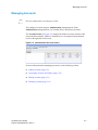
Understanding the Management Tabs
UniVista is divided into two management tabs (see Figure 2-5):
System Summary - Used for device, schedule, and alarm management. For more
information on the System Summary tab, see System Summary Tab (page 2-5).
Administration - Used for account/permission management. For more information
on the Administration tab, see Administration Tab (page 2-6).
Figure 2-5
Management Functions
Management Tabs
2-4
UniVista User’s Guide
Part No. 600-09000-001, Rev. 2
Beta Draft Confidential
Understanding the Management Tabs
System Summary Tab
The System Summary management tab (see Figure 2-5) allows you to manage and
schedule your devices, as well as monitor alarm activity. It is divided into the
following two frames:
Status Frame - Displays the folder tree that contains all the devices organized by
location as well as their current status and settings. For more information about the
folder tree, see Understanding the Folder Tree (page 2-7).
Function Frame - Used to configure the devices and access the log files. For more
information about the Function Frame, see Accessing the Management Functions
(page 4-2).
Table 2-1 describes the icons located under the System Summary tab.
Table 2-1
ICON
System Summary Tab Icons
Click to...
Display the columns in the Status Frame to the lowest amount of space needed for
that column to be displayed.
Display all the devices with alarms in the folder tree.
Display and hide the Function Frame.
Select which column(s) you want to display in the Function Frame.
Select how often you want the screen to automatically refresh: 15 Seconds. 30
Seconds, 45 Seconds, 1 Minute, or 5 Minutes.
UniVista User’s Guide
Part No. 600-09000-001, Rev. 2
2-5
Beta Draft Confidential
CHAPTER 2: Navigating UniVista
Administration Tab
The Administration management tab allows you to configure and manage user
accounts.
Table 2-2 describes the icons located under the Administration tab.
Table 2-2
ICON
Administration Tab Icons
Click to...
Add a user account.
Associate a user account and folder.
Edit a user account.
Delete a user account.
Note
2-6
For more information on managing user accounts, see Managing Accounts (page
5-7).
UniVista User’s Guide
Part No. 600-09000-001, Rev. 2
Beta Draft Confidential
Understanding the Folder Tree
Understanding the Folder Tree
Each management tab uses a navigation hierarchy displayed as a “folder tree” (see
Figure 2-6) to manage the information with which it is associated. The folder tree
looks similar to the directory structure in Windows Explorer.
In the:
Note
System Summary tab, the folder tree is displayed in the Status Frame and is
divided into three main folders:
–
Devices - Displays all the devices that have been assigned to a specific folder.
–
Unassigned Devices - Displays all the devices that have not been assigned to
a folder.
–
Configurations - Displays the various configuration files you create and
store. For more information, see Using Configuration Files (page 5-21).
Administration tab, the folder tree is displayed in the Accounts Frame.
UniVista displays only those folders associated with the specific user’s account
permission level to which they are assigned. For more information about user
accounts, see Managing Accounts (page 5-7).
Figure 2-6
Folder Tree
Folder Tree
UniVista User’s Guide
Part No. 600-09000-001, Rev. 2
2-7
Beta Draft Confidential
CHAPTER 2: Navigating UniVista
Each folder may contain sub-folders and/or devices. The folders expand and collapse
and you can navigate through the folder by:
Note
double-clicking anywhere on the folder line.
clicking the
or
to the left of the folder icon.
You can manage each Proliphix device individually by accessing the panel
associated with each device. To save time, UniVista groups certain management
tasks and enables you to apply these tasks to multiple devices at the same time.
Although you can create custom names for folders, Proliphix recommends using a
six-level hierarchical structure similar to the one shown below:
Region (Massachusetts)
County (Middlesex County)
Town (Bedford)
School (Bedford High School)
Building (Building A)
Floor (First Floor)
2-8
UniVista User’s Guide
Part No. 600-09000-001, Rev. 2
BetaUnderstanding
DraftModes
Confidential
of Operation Using Single Device Selection and Group Device(s) Selection
Understanding Modes of Operation Using Single Device
Selection and Group Device(s) Selection
UniVista supports the following two modes of operation for selecting devices:
Single Device Selection - For information on selecting a single device, see Single
Device Selection Mode (page 2-9).
Group Device Selection - For information on selecting multiple devices, see Group
Device(s) Selection Mode (page 2-10).
Single Device Selection Mode
A Single Device selection occurs when you click and highlight the name of an
individual device but do not click (check) the box in front of the device name. When
you select a single device it displays its current status across the Status Frame page, as
well as the selected Function Frame page.
For example, in Figure 2-7 Steam Table is highlighted (notice the box is not checked)
and therefore displays all its information on both the Status Frame page and the Status
& Control information on the Function Frame page.
Figure 2-7
Single Device Selection Mode Example
Steam Table
Note
Function Frame page display
In Single Device Selection Mode, you can monitor and configure that specific
device only.
UniVista User’s Guide
Part No. 600-09000-001, Rev. 2
2-9
CHAPTER 2: Navigating UniVista
Beta Draft Confidential
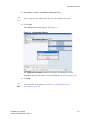
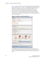
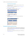
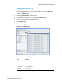
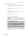
Group Device(s) Selection Mode
A Group Device selection occurs when you click (check) the box next to each device.
As soon as you click the box in front of a device it is considered to be in Group mode
(Group View). When you select one or more devices by clicking the box in front of
the device(s), it displays its current status across the Status Frame page, however the
Function Frame page does not display any specific information. Whether you select a
single device or multiple devices, the Function Frame displays “--” in all the fields,
which indicates that each device in the group may be configured differently.
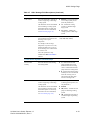
For example, in Figure 2-8 the Steam Table box is clicked (checked) and the line is
highlighted, therefore all its information is displayed on the Status Frame page.
However, the Status & Control information on Function Frame page displays “--” in
all the fields.
Figure 2-8
Group Device(s) Selection Mode Example
Box selected device
Steam Table
Note
2-10
In Group Device Selection Mode, you can monitor and configure one or more
devices at a time, which is referred to as “bulk” or “multiple” configuration
changes. For more information, see Performing Bulk or Multiple Configuration
Changes (page 2-11).
UniVista User’s Guide
Part No. 600-09000-001, Rev. 2
BetaUnderstanding
DraftModes
Confidential
of Operation Using Single Device Selection and Group Device(s) Selection
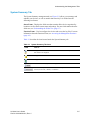
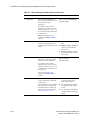
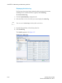
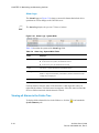
Performing Bulk or Multiple Configuration Changes
This feature enables you to make configuration changes to multiple devices at the
same time. You can select multiple devices and make a change or changes to certain
parameters. When you submit this change, all clicked (checked) devices (or Group
members) receive this same change at the same time. This allows you to update or
change device settings at multiple remote locations with one single submission.
For example, you have a need to change the heat setting on three devices and each
device is on their own separate floor (1st FL, 2nd FL & 3rd FL) in the building. You
can simply click (check) the box for each device. Go to the Function Frame page and
set the heat to the new temperature you want all three devices set to and click Submit.
All three devices are updated simultaneously. This eliminates the need to go to three
different devices on your system and make the changes individually or manually go to
each thermostat on each floor and make the changes.
For example, Figure 2-9 displays three devices where their heat/cool temperatures are
changed simultaneously by the one command. It also displays those changes in yellow
highlight, which indicates the change took place and is in the override condition
temporarily.
Figure 2-9
Bulk Configuration Changes Example
Yellow highlighted devices
UniVista User’s Guide
Part No. 600-09000-001, Rev. 2
2-11
CHAPTER 2: Navigating UniVista
Beta Draft Confidential
Summary of Selecting a Single Device or Mulitple Devices
To select a single device or multiple devices:
Note
Note
Note
2-12
1
Click the System Summary management tab.
2
From the folder tree, do one of the following to identify the device(s) you want to add:
To select a single device, click the name of the device and verify there is not a
check in the box.
To select multiple devices, click the boxes next to each device.
To select a specific group of devices, load the appropriate group. For information
about loading groups, see Loading a Group (page 5-16).
You can also add devices to and remove devices from a group. For more
information, see Adding Devices to and Removing Devices from a Group (page
5-17).
If multiple devices are selected because a group is loaded or boxes are checked
and you highlight a device outside of the group then you are unable to make
changes to that single highlighted device or to the group. If you want to make
changes to the highlighted device then you must first unload the group. If you want
to make change to the group then you must first highlight a member of the group.
If you select a single device then Function Frame displays the configuration
information for that specific device. If you select more than one device then
Function Frame displays “--” in all the fields indicating that each device in the
group may be configured differently.
UniVista User’s Guide
Part No. 600-09000-001, Rev. 2
Beta Draft Confidential
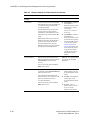
Understanding Account Permission Levels
Understanding Account Permission Levels
UniVista supports three different levels of accounts and permissions. These
permissions are associated with a user’s hierarchy in the folder tree and determine the
actions the user can perform and the window(s) they can view and/or access and edit.
UniVista supports the following account permission levels:
Administrator - Has ability to do perform all functions: manipulate the folder tree,
apply configuration changes to one or more devices, manage the application settings,
and administer accounts.
There may be only one Administrator account.
Note
Manager - Has ability to apply application changes to one ore more devices.
User - Has ability to view only the folder/devices to which they are assigned.
Note
Users cannot make any changes to any devices within the folders to which they are
assigned.
UniVista User’s Guide
Part No. 600-09000-001, Rev. 2
2-13
CHAPTER 2: Navigating UniVista
2-14
Beta Draft Confidential
UniVista User’s Guide
Part No. 600-09000-001, Rev. 2
Beta Draft Confidential
Chapter
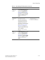
3
Configuring UniVista Parameters
This chapter describes how to initially configure UniVista, which includes system
setup information, adding folders, and adding devices to the folders.
Specifically, it describes the following sections:
Note
Configuring System Setup Information (page 3-3)
Adding a Folder (page 3-5)
Adding a Device (page 3-6)
This chapter lists the tasks in the order in which they should be performed to add a
device.
Only the Administrator may perform any of the tasks listed in this chapter.
Note
UniVista User’s Guide
Part No. 600-09000-001, Rev. 2
3-1
CHAPTER 3: Configuring UniVista Parameters
Beta Draft Confidential
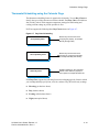
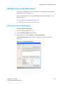
Figure 3-1 outlines the necessary steps to add a device to UniVista and shows the
menu path to access each step. You should perform each task in the order shown in
Figure 3-1.
Figure 3-1
1
2
3
3
3-2
Adding a Device Overview
Configuring System Setup Information (page 3-3)
Adding a Folder (page 3-5)
Adding a Device (page 3-6)
UniVista User’s Guide
Part No. 600-09000-001, Rev. 2
Beta Draft Confidential
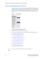
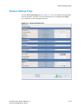
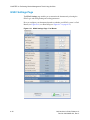
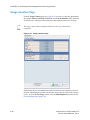
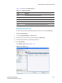
Configuring System Setup Information
Configuring System Setup Information
From the Administration management tab you can add the SMTP Server IP Address
and contact E-mail address.
To configure the System Setup information:
1
Click the Administration management tab.
2
Select System => System Setup.
The System Setup window appears. See Figure 3-2.
Figure 3-2
UniVista User’s Guide
Part No. 600-09000-001, Rev. 2
System Setup Window
3-3
CHAPTER 3: Configuring UniVista Parameters
3
Beta Draft Confidential
Complete the fields as described in Table 3-1.
Table 3-1
Administrations - System Setup Fields
Field
Description
Callhome Server IP Address Settings
Server Direct IP
Address
The IP address of the UniVista server. This may be a local IP address if your
UniVista server is on your local network (LAN) or may be a remote IP address if
your UniVista Server is at a remote site.
Note: This Server Direct IP Address is determined automatically to match the
given MAC address and cannot be configured.
Server Direct
Port
The port on which UniVista is listening for HTTP requests.
Firewall IP
Address
The IP address of the server as seen on the public side of the firewall, if a firewall
exists. Consult your IT professionals for this address information.
Firewall Port
The port of the server as seen on the public side of the firewall, if a firewall
exists. Consult your IT professionals for this address information.
Note: The default port used is port 80 and cannot be configured.
SMTP Server Settings
SMTP Server IP
Address
The SMTP server IP address, which is the same as the SMTP Server IP Address
or DNS name.
SMTP Server
Port
The SMTP server port.
SMTP Username
Note: The default port used is 25 and the port address may be configured.
The SMTP username, if needed, which is the username associated with your
SMTP Server provider.
Note: This field is left blank if your SMTP server does not require authentication.
SMTP Password
The SMTP password, if needed, which is the password associated with your
SMTP Username.
Note: This field is left blank if your SMTP server does not require authentication.
From E-mail
Address
The E-mail address UniVista uses to notify the SMTP server.
Test E-mail Settings
E-mail Address
The E-mail address UniVista uses to test the SMTP settings. When you click
Send Test then a test E-mail is generated and sent to this address.
Note: This E-mail address is not stored in the database.
Maintenance E-mail Settings
E-mail Address
The E-mail address UniVista uses to forward the logs for diagnostic information.
Note: This E-mail address is not stored in the database.
4
3-4
Click Submit to save the information.
UniVista User’s Guide
Part No. 600-09000-001, Rev. 2
Beta Draft Confidential
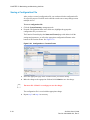
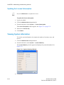
Adding a Folder
Adding a Folder
You can add a folder from the main menu, as well as from the folder tree itself.
To add a new folder:
1
Click the System Summary management tab.
2
Click the folder into which you want to add a folder.
3
Do one of the following:
Right-click and select Add Folder.
From the main menu, select Folder => Add Folder.
The Add Folder window appears. See Figure 3-3.
Figure 3-3
Add Folder Window
4
Enter a Name (required) and Description (optional) for the new folder.
5
Click Submit.
The folder appears beneath the higher level folder in the folder tree.
Note
You cannot rename or delete the three highest level folders: Device, Unassigned
Devices, and Configurations.
UniVista User’s Guide
Part No. 600-09000-001, Rev. 2
3-5
CHAPTER 3: Configuring UniVista Parameters
Beta Draft Confidential
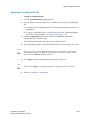
Adding a Device
You can add a device to a folder from the main menu, as well as from the folder tree
itself.
To add a device to a folder:
1
Click the System Summary management tab.
1
Click the folder into which you want to add a device.
2
Do one of the following:
Right-click and select Add Device.
From the main menu, select Device => Add Device.
The Add Device window appears. See Figure 3-4.
Figure 3-4
3-6
Add Device Window
UniVista User’s Guide
Part No. 600-09000-001, Rev. 2
Beta Draft Confidential
3
Adding a Device
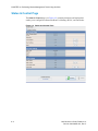
Complete the fields as described in Table 3-2.
Table 3-2
Add Device Fields
Field
Description
Device Settings
Name
Complete this field to have UniVista set the device’s name when the
device is added. If this field is left blank, the current device name is
preserved.
Type
The hardware device identifier.
Description
Complete this field to record information about the device such as physical
location, control area, etc.
Note: The information is stored in UniVista and not in the device itself.
Admin Password
Admin Password
Complete this field to specify the Administrator password of the device it
is different from the default admin.
Note: This does not change the Administrator password.
Network Settings
Device IP Address
The direct IP address of the device if there is no firewall located between
the UniVista server and the device. If there is a firewall then this is the IP
address of the firewall.
IP Addr Method
The dynamic (DHCP) or static assignment.
Device Port
The direct port of the device if there is no firewall located between the
UniVista server and the device. If this field is left blank then the default
value of 80 is used. If there is a firewall then this is the firewall port to
which the device has been mapped.
Server Network Settings
Device Location
Specifies if communication from the UniVista server to the device must
pass through a firewall.
If there is no firewall between the UniVista server and the device then
choose Direct.
If there is a firewall then choose Behind Firewall.
Note: This is only for the direction from the UniVista server to the device.
Server Location
Specifies if communication from the device to the UniVista server must
pass through a firewall.
If there is no firewall between the device and the UniVista server then
choose Direct.
If there is a firewall then choose Behind Firewall.
Note: This is only for the direction from the device to the UniVista server.
Time Zone Settings
UniVista User’s Guide
Part No. 600-09000-001, Rev. 2
Specifies the time zone in which the device is physically located.
3-7
CHAPTER 3: Configuring UniVista Parameters
4
Beta Draft Confidential
Click Submit.
The device is listed within the folder in the folder tree.
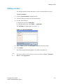
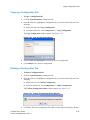
Example 1
Figure 3-5 is an example of a simple network setup where the UniVista server and all
devices are located on a local area network. There may be separate Ethernet segments
as shown below (192.168.111.x, 192.168.112.x), but all devices are directly
accessible from the UniVista server.
Figure 3-5
Example 1 - Simple Network
192.168.111.115
192.168.111.34
Office #1
UniVista Server
192.168.111.x
192.168.111.35
Hall #1
Router
192.168.112.x
192.168.112.45
Atrium #2
3-8
UniVista User’s Guide
Part No. 600-09000-001, Rev. 2
Beta Draft Confidential
Adding a Device
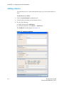
Figure 3-6 shows the Add Device window for adding the thermostat labeled Atrium
#2 shown in Figure 3-5. The Atrium #2 thermostat has a non-default admin password.
Both the Server Location and Device Location fields are set to Direct. The Server
Network Settings shows both firewalls disabled since there is no firewall in this
device addition. However, the Server Firewall shows an IP address because the Server
Firewall field has been set in the System Setup dialog.
Figure 3-6
UniVista User’s Guide
Part No. 600-09000-001, Rev. 2
Example 1 - Add Device Window
3-9
CHAPTER 3: Configuring UniVista Parameters
Beta Draft Confidential
Example 2
Figure 3-7 shows an example of a network configuration that contains firewalls in
front of the devices. This situation can occur when different departments within an
organization have firewalls to control access to their local networks. Note that there is
no firewall in front of the UniVista server and on the diagram the Port Forwarding
information to allow access to the devices.
Figure 3-7
Example 2 - Single Firewall
192.168.0.x
192.168.111.115
UniVista Server
Device
192.168.0.35 is
“Port Forwarded”
to Port 8080
192.168.111.201
192.168.0.35
Office #2
192.168.111.x
192.168.111.200
Device
192.168.0.45 is
“Port Forwarded”
to Port 8081
192.168.0.45
192.168.111.5
Hall #1
Atrium #2
192.168.0.x
3-10
UniVista User’s Guide
Part No. 600-09000-001, Rev. 2
Beta Draft Confidential
Adding a Device
Figure 3-8 shows the Add Device window for adding the thermostat labeled Office #2
shown in Figure 3-7. In this example, the device was just installed and the Name field
is filled in so the device is assigned a name during setup. The Admin Password field is
blank since the admin password is the default value. Note how in the Server Network
Settings that the Device IP Address line has changed to Firewall IP Address. This is
because Device Location was set to Firewall. The value of the IP address is set to that
of the firewall and the Firewall port is set to 8080 to correspond to the port forwarding
setup.
Figure 3-8
UniVista User’s Guide
Part No. 600-09000-001, Rev. 2
Example 2 - Add Device Window
3-11
CHAPTER 3: Configuring UniVista Parameters
Beta Draft Confidential
Example 3
Figure 3-9 shows a network with firewalls located at both the UniVista server and at
the devices. In this example, The UniVista server is located in the Main Office
location. The devices are located locally within the Main Office and at remote store
locations. The Internet is used to tie the store locations to the Main Office.
Figure 3-9
Example 3 - Double Firewall
192.168.0.45
192.168.111.115
Floor #2
The UniVista
Server is “Port
Forwarded” to
Port 81
192.168.0.x
The device
192.168.0.45 is
“Port Forwarded”
to Port 8080
69.14.117.200
External Internet
Address
UniVista Server
70.11.111.34
External Internet
Address
192.168.111.x
Internet
192.168.111.5
Hall #1
90.11.111.35
External Internet
Address
Store #3
91.112.11.35
External Internet
Address
The device
192.168.0.45 is
“Port Forwarded”
to Port 8080
Main Office
192.168.0.x
The device
192.168.0.45 is
“Port Forwarded”
to Port 8080
192.168.0.45
192.168.0.x
192.168.0.45
Floor #2
3-12
Floor #2
Store #2
Store #1
UniVista User’s Guide
Part No. 600-09000-001, Rev. 2
Beta Draft Confidential
Adding a Device
Figure 3-10 shows the Add Device window for adding the thermostat labeled Hall #1.
shown in Figure 3-9. This device was previously installed so that no Name field is
needed. The Admin Password field is needed because it has been changed.
Figure 3-10
UniVista User’s Guide
Part No. 600-09000-001, Rev. 2
Example 3 - Add Device Window #1
3-13
CHAPTER 3: Configuring UniVista Parameters
Beta Draft Confidential
Figure 3-11 shows the Add Device window for adding the thermostat labeled Floor #2
in Store #3 shown in Figure 3-9. This is a new installation such that the Name field is
populated. The Firewall IP Address is set to the IP address of Store #3’s firewall.
Store #3’s firewall has been setup to port forward external port 8080 to the
192.168.0.45 device. Notice how both location fields have been set to Behind
Firewall. The Server Network Settings diagram reflects the logical layout of the
network. The Device, Floor #2 does not show an IP address because it is unknown
until the device has been added to the UniVista server. A later call to Edit Device will
show the local IP address.
Figure 3-11
Example 3 - Add Device Window #2
The remaining devices can be added in a similar fashion. If more than one device
exists at a location, multiple port forwarding entries will be required. Each device will
have the same Firewall IP address. However, the Firewall Port will change for each
device.
3-14
UniVista User’s Guide
Part No. 600-09000-001, Rev. 2
Beta Draft Confidential
Chapter
4
Performing Device Management Tasks
Using UniVista
This chapter describes how to access the Function Frame and perform
device-management tasks, for example: display the temperature status, schedule, and
HVAC settings, configure addressing and security information, and configure HVAC
type and heating/cooling cycles.
Specifically, it describes how to use the following pages to perform the appropriate
device-management task with which the page is associated:
Status & Control Page (page 4-4)
General Settings Page (page 4-10)
Alarms Settings Page (page 4-14)
Schedules Settings Page (page 4-18)
Network Settings Page (page 4-25)
HVAC Settings Page (page 4-30)
Sensor Settings Page (page 4-42)
Remote Access Page (page 4-45)
Installer Info Page (page 4-49)
Usage Counters Page (page 4-50)
UniVista User’s Guide, Release 1.0
Part No. 600-09000-001, Rev. 2
4-1
Beta Draft Confidential
CHAPTER 4: Performing Device Management Tasks Using UniVista
Accessing the Management Functions
Function Frames are used to control a single or group of Network Thermostats and are
purposely similar to the respective Network Thermostat Web pages. Function Frame
parameters are easily modified through convenient drop-down menus, which provide
for unprecedented ease of schedule programming and HVAC settings changes. See
Figure 4-1.
Figure 4-1
Function Frame
To display the device-management tasks:
1
From the Function Frame, click the drop-down list.
2
Select an option from the drop-down list and continue with the appropriate section:
Status & Control Page (page 4-4)
General Settings Page (page 4-10)
Alarms Settings Page (page 4-14)
Schedules Settings Page (page 4-18)
Network Settings Page (page 4-25)
HVAC Settings Page (page 4-30)
Sensor Settings Page (page 4-42)
Remote Access Page (page 4-45)
Installer Info Page (page 4-49)
Usage Counters Page (page 4-50)
The Function Frame displays the fields specific to each device.
Note
4-2
UniVista User’s Guide, Release 1.0
Part No. 600-09000-001, Rev. 2
Beta Draft Confidential
Note
Accessing the Management Functions
For information about viewing the Log files, see Viewing Action and Alarm
Information (page 5-28).
UniVista User’s Guide, Release 1.0
Part No. 600-09000-001, Rev. 2
4-3
Beta Draft Confidential
CHAPTER 4: Performing Device Management Tasks Using UniVista
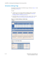
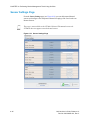
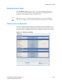
Status & Control Page
The Status & Control page (see Figure 4-2) contains parameters and settings that
enable you to configure the thermostat Heat/Cool Settings, HVAC, and Fan modes.
Figure 4-2
4-4
Status and Control Page
UniVista User’s Guide, Release 1.0
Part No. 600-09000-001, Rev. 2
Beta Draft Confidential
Status & Control Page
Table 4-1 describes the Status and Control fields. Modify the fields as necessary and
click Submit.
Table 4-1
Status and Control Field Descriptions
Field
Description
Parameters
Displays the current temperature of the
local sensor if temperature averaging is
disabled.
-30°F(-34°C) to 199°F(95°C)
Temperature
Zone Temperature
Average temperature of any combination of
Local, Remote Sensor #1 (RS #1) or
Remote Sensor #2 (RS #2) if temperature
averaging is enabled.
Local (Temperature)
Displays the current temperature of the
local sensor.
45°F(7°C) to 95°F(35°C)
Note: This field appears grey if the local
thermostat is enabled but not included in
temperature averaging and does not appear
at all if the local thermostat is not enabled.
Note: This field is not applicable on the
NT100e/h thermostat.
RS #1
Displays the current temperature of Remote
Sensor #1 if this remote thermal sensor is
installed and enabled.
-30°F(-34°C) to 199°F(95°C)
Note: This field appears grey if RS #1 is
enabled but not included in temperature
averaging and does not appear at all if
RS #1 is not enabled.
Note: This field is not applicable on the
NT100e/h thermostat.
RS #2
Displays the current temperature of Remote
Sensor #2 if this remote thermal sensor is
installed and enabled.
-30°F(-34°C) to 199°F(95°C)
Note: This field appears grey if RS #2 is
enabled but not included in temperature
averaging and does not appear at all if
RS #2 is not enabled.
Note: This field is not applicable on the
NT100e/h thermostat.
UniVista User’s Guide, Release 1.0
Part No. 600-09000-001, Rev. 2
4-5
Beta Draft Confidential
CHAPTER 4: Performing Device Management Tasks Using UniVista
Table 4-1
Status and Control Field Descriptions (Continued)
Field
Description
Parameters
Relative Humidity
(NT150e/h,
NT160e/h, and
TM250e/h only)
Displays the relative humidity for the
thermostat.
10% to 90% RH
Override
Displays whether Heat or Cool settings are
different from the current scheduled
settings.
The NT150e/h, NT160e/h, and TM250e/h
thermostats are capable of measuring the
relative humidity of the local air. The
relative humidity is sampled once per
minute and has an accuracy of ±3.0%. The
reading includes temperature compensation
for temperature readings significantly
different from 77°F.
Changes made to either the Heat or Cool
settings (which force an override) remain at
those settings until the next scheduled
Period change. At the Period change, the
settings for either/both heat or cool follow
the schedule. For more information, see
Schedule Settings (page 4-7).
Cool Setting
Select the current temperature programmed
for the cooling (A/C) system.
40°F(4.5°C) to 99°F(37°C)
Note: This field appears grey if the HVAC
Mode is set to Heat or Off and does not
appear at all if Cool Control setting on the
HVAC Settings page is disabled.
Heat Setting
Select the current temperature programmed
for the heating system.
40°F(4.5°C) to 99°F(37°C)
Note: This field appears grey if the HVAC
Mode is set to Cool or Off and does not
appear at all if Heat Control setting on the
HVAC Settings page is disabled.
Hold
or
Hold/OBO
(NT130e/h and
NT160e/h only)
4-6
Displays the current state for both the Heat
and Cool setting.
Note: When activated on the NT130e/h and
NT160e/h the Hold function changes to One
Button Overide and the Hold duration
setting is used as an OBO duration setting.
Hold – Hold mode is
enabled. (Does not apply
to NT130e/h and
NT160e/h)
Off (default) – Hold
mode is disabled.
One Button Override One Button Override is
enabled (NT130e/h and
NT160e/h only)
UniVista User’s Guide, Release 1.0
Part No. 600-09000-001, Rev. 2
Beta Draft Confidential
Table 4-1
Status & Control Page
Status and Control Field Descriptions (Continued)
Field
Description
Parameters
Schedule Settings
Day Class
Displays the current settings for the
scheduled Day Class. For more
information, see Schedules Settings Page
(page 4-18).
Period
Displays the current settings for the
scheduled Period. For more information,
see Schedules Settings Page (page 4-18).
Cool
Displays the current Cool temperature
setting as set within the current Day Class
schedule. For more information, see
Schedules Settings Page (page 4-18).
40°F(4.5°C) to 99°F(37°C)
Heat
Displays the current Heat temperature
setting as set within the current Day Class
schedule. For more information, see
Schedules Settings Page (page 4-18).
40°F(4.5°C) to 99°F(37°C)
UniVista User’s Guide, Release 1.0
Part No. 600-09000-001, Rev. 2
4-7
Beta Draft Confidential
CHAPTER 4: Performing Device Management Tasks Using UniVista
Table 4-1
Status and Control Field Descriptions (Continued)
Field
Description
Parameters
Displays the current state of the heating or
cooling system. If a state change is made
while viewing this page, click Refresh to
update the status.
Heat – First stage heat is
actively heating.
Heat2 – First stage and
second stage heat are
actively heating. (Fuel
Burner)
Aux Ht – First stage and
auxiliary heat are actively
heating. (Heat Pump)
Cool – First stage cool is
actively cooling.
Cool2 – First stage and
second stage A/C are
actively cooling.
Off – Neither the heating
system or cooling system
is active.
Off – The thermostat is
disabled from controlling
either the heating or
cooling system.
Heat – Heating system
only.
Cool – Cooling system
only.
Auto – Automatic
changeover between
heating and cooling
systems.
Off – The operation of the
fan is off.
On – The fan is
operating.
HVAC Settings
HVAC State
HVAC Mode
Select and controls the current mode setting
for the HVAC system.
The thermostat can be configured to control
the heat system only, cool system only,
automatically change over between heating
and cooling systems, or control neither
system.
Fan Relay State
4-8
Displays the current state of the HVAC fan.
UniVista User’s Guide, Release 1.0
Part No. 600-09000-001, Rev. 2
Beta Draft Confidential
Table 4-1
Status & Control Page
Status and Control Field Descriptions (Continued)
Field
Description
Parameters
Fan Mode
Select and control the current state setting
for the HVAC fan.
Auto – Heating or
cooling system controls
the operation of the fan.
On – User forces the fan
to the on state
independent of the
operation of the HVAC
system.
Schedule – The operation
of the fan adheres to a
schedule as defined by the
user on the Occupied,
Unoccupied, and Other
Day Class pages. For
more information, See
Schedules Settings Page
(page 4-18).
Note: When in Schedule
mode, the fan continues
to work in Auto mode as
well.
Active – The External
Relay has been activated.
Inactive – The External
Relay is not active.
External Relay State
(NT150e/h,
NT160e/h, and
TM250e/h only)
UniVista User’s Guide, Release 1.0
Part No. 600-09000-001, Rev. 2
Displays the current state of the External
Relay.
4-9
Beta Draft Confidential
CHAPTER 4: Performing Device Management Tasks Using UniVista
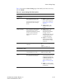
General Settings Page
The General Settings page (see Figure 4-3) contains parameters and settings that
enable you to configure the thermostat name and location and set filter replacement
reminders.
Figure 4-3
4-10
General Settings Page
UniVista User’s Guide, Release 1.0
Part No. 600-09000-001, Rev. 2
Beta Draft Confidential
General Settings Page
Table 4-2 describes the General Settings fields. Modify the fields as necessary and
click Submit.
Table 4-2
General Settings Field Descriptions
Field
Description
Parameters
Enter a name for the device.
Unique 13 character
identifier
Zone Name
Device Name
You can use the thermostat location in this
field, for example, Classroom 1. This identifier
is known as the host name within the data
network.
Site Name
Enter a name used to identify the thermostat if
more than one thermostat intercommunicates
with the Proliphix Web Server.
25 alpha-numeric
character name
For more information, see the Proliphix
Remote Access Guide.
Thermostat
Serial Number
Displays the device’s serial number.
Firmware Version
Displays the firmware version.
Model Number
Displays the hardware model.
Hardware Version
Displays the hardware version.
Backlight
Select the LCD backlight control.
Display Contrast
UniVista User’s Guide, Release 1.0
Part No. 600-09000-001, Rev. 2
Select a value between 20 (lowest contrast
between the graphics characters and the
background) and 40 (highest character contrast
to the background) to indicate the LCD display
contrast control.
Eight digit alpha-numeric
thermostat serial number,
for example, 8438F399
Delay (default) – The
backlight is
illuminated when you
click a button and
remains illuminated
for 16 seconds after
the last button is
clicked.
Off – The backlight is
disabled from
activation. An
ambient backlight
remains visible.
20, 22, 24, 26, 28
(default), 30, 32, 34, 36,
38, 40
4-11
Beta Draft Confidential
CHAPTER 4: Performing Device Management Tasks Using UniVista
Table 4-2
General Settings Field Descriptions (Continued)
Field
Description
Parameters
Button Lockout
Select to indicate the Button Lockout status.
Disable (default) –
Allows normal
thermostat button
activity.
Enable – Prevents
user access at the
thermostat button
interface except for
limited or no
temperature
adjustments.
0 (default) – No
temperature
adjustments are
allowed. All
thermostat buttons are
disabled.
1 through 20 –
(Fahrenheit) Allowed
temperature limits
above and below the
current scheduled
temperature settings.
For example, if this
value is set to 2, the
Up and Down buttons
may be used to select
a temperature within
the range of 2°F
below/above the
current scheduled
temperature set point.
.5 through 10 –
(Celsius) Allowed
temperature limits
above and below the
current scheduled
temperature settings.
When enabled, this feature prevents a user
from directly altering the settings of the
thermostat from the thermostat’s button
interface and the button lockout icon appears
on the thermostat LCD screen.
When Button Lockout is:
Set Point Override
Disabled, this specifies the time interval
for the Hold function in which the
thermostat temperature settings are held
independent of schedule changes due to
Period or Day Class advancements.
Enabled on the NT130e/h and NT160e/h,
the Hold function on the Status and
Control page changes to Hold/OBO and
the Hold duration setting is used as an
OBO duration setting.
Select to restrict the use of the thermostat
buttons to allow only limited temperature
adjustments to be made above and below the
preset temperature schedules.
Note: This field is disabled if Button Lockout
is set to Disable.
4-12
UniVista User’s Guide, Release 1.0
Part No. 600-09000-001, Rev. 2
Beta Draft Confidential
Table 4-2
General Settings Page
General Settings Field Descriptions (Continued)
Field
Description
Parameters
Date and Time
Set Date and Time
Displays the date, time, and time zone of the
selected device, along with the current local
time for reference.
The Set Date and Time function is used to
immediately update the time on a device.
Under normal operation, the UniVista server
sets the device’s time once a day to ensure
proper schedule operation.
Set Time
Click to set the time and date on the device.
The date and time of the device can be set by
clicking the Set Time checkbox and clicking
Submit. The time that is set on the device is
determined on the UniVista server according to
the server’s time and the device’s time zone.
US DST
Click to indicate whether the thermostat should
adhere to the Unites States Daylight Savings
Time program, while maintaining the date and
time U.S.
Daylight Savings Time (US DST) stipulates
that the time shall be set ahead an hour at the
end of the first Saturday of the month of April
every year. In addition, the time shall be set
back an hour at the end of the last Saturday of
the month of October every year.
Save and Restore Configuration
Configuration
UniVista User’s Guide, Release 1.0
Part No. 600-09000-001, Rev. 2
Save
Restore
4-13
Beta Draft Confidential
CHAPTER 4: Performing Device Management Tasks Using UniVista
Alarms Settings Page
The Alarm Settings page (see Figure 4-4) contains parameters and settings that
enable you to configure alarm information.
Figure 4-4
Alarm Settings Page
Table 4-3 describes the Alarm Settings fields. Modify the fields as necessary and
click Submit.
Table 4-3
Alarm Settings Field Descriptions
Field
Description
Parameters
Select to indicate the low temperature
threshold detection status.
The value set by this parameter is
monitored by the thermostat and
compared against the current Zone
Temperature. If the current Zone
Temperature falls below this value,
an alarm condition is set and the status
is displayed on the Status & Control
Page (page 4-4).
Zone Alarms
Low
Temp(erature)
Limit
Disable (default) – No low
temperature limit is set.
-30°F(-34.5°C) to 200°F(93°C)
In addition, this alarm will be sent to
the Proliphix web site to trigger an
E-mail notification if this function is
Enabled.
Note: This is a major (red) alarm
condition.
4-14
UniVista User’s Guide, Release 1.0
Part No. 600-09000-001, Rev. 2
Beta Draft Confidential
Table 4-3
Alarms Settings Page
Alarm Settings Field Descriptions (Continued)
Field
Description
Parameters
Low
Temp(erature)
Dismiss
If a Low Temp Limit alarm is set and
is noted in the Low Temp Dismiss
field then the Condition Repaired
box must be checked and the Zone
Temperature must be above the Low
Temp Limit or the Low Temp Limit
must be set to Disable for the alarm
condition to be cleared upon a
Submit.
High
Temp(erature)
Limit
Select to indicate the high temperature
threshold detection status.
The value set by this parameter is
monitored by the thermostat and
compared against the current Zone
Temperature. If the current Zone
Temperature rises above this value, an
alarm condition is set and the status is
displayed on the Status & Control
Page (page 4-4). In addition, this
alarm is sent to the Proliphix web site
to trigger an E-mail notification if this
function is Enabled.
Disable (default) – No high
temperature limit is set.
-30°F(-34.5°C) to 200°F(93°C)
Note: This is a major (red) alarm
condition.
High
Temp(erature)
Dismiss
UniVista User’s Guide, Release 1.0
Part No. 600-09000-001, Rev. 2
If a High Temp Limit alarm is set and
is noted in the High Temp Dismiss
field then the Condition Repaired
box must be checked and the Zone
Temperature must be below the High
Temp Limit or the High Temp Limit
must be set to Disable for the alarm
condition to be cleared upon a
Submit.
4-15
Beta Draft Confidential
CHAPTER 4: Performing Device Management Tasks Using UniVista
Table 4-3
Alarm Settings Field Descriptions (Continued)
Field
Description
Parameters
High Humidity
Limit
(NT150e/h and
NT160e/h only)
Select to indicate the high humidity
threshold detection status.
Disable (default) – No high
humidity limit is set.
This value is monitored by the
thermostat and compared against the
current Relative Humidity. If the
current Relative Humidity rises
above this value, an alarm condition is
set and the status is displayed on the
Status & Control Page (page 4-4). In
addition, this alarm is sent to the
Proliphix web site to trigger an E-mail
notification if this function is
Enabled.
10%RH to 90%RH – High
Humidity Limit in 5%
increments.
If a High Humidity Limit alarm is set
and is noted in the High Humidity
Dismiss field then the Condition
Repaired box must be checked and
the relative humidity must be below
the High Humidity Limit or the High
Humidity Limit must be set to
Disable for the alarm condition to be
cleared upon a Submit.
Note: This is a major (red) alarm
condition.
High
Temp(erature)
Dismiss
4-16
If a High Temp Limit alarm is set and
is noted in the High Temp Dismiss
field then the Condition Repaired
box must be checked and the Zone
Temperature must be below the High
Temp Limit or the High Temp Limit
must be set to Disable for the alarm
condition to be cleared upon a
Submit.
UniVista User’s Guide, Release 1.0
Part No. 600-09000-001, Rev. 2
Beta Draft Confidential
Table 4-3
Alarms Settings Page
Alarm Settings Field Descriptions (Continued)
Field
Description
Parameters
Select to remind you that the HVAC
system requires maintenance.
Disables (default) – Interval
reminder disabled.
This feature allows you to set time
intervals between changing and/or
cleaning the HVAC filter. If enabled,
an alarm condition is set after the
pre-set interval has expired, and is
displayed on the Status & Control
Page (page 4-4).
10, 30, 60, 90, 120, 240, 365
Runtime Days – The runtime
interval after which an alarm will
be set to remind the user of the
need for HVAC maintenance.
Filter Alarms
Filter (change)
Reminder
In addition, this alarm is sent to the
Proliphix web site to trigger an E-mail
notification if this function is
Enabled.
Note: This is a minor (yellow) alarm
condition.
The TMI displays the following additional fields upon different settings and conditions of the Filter
Reminder state.
Filter Usage
Displays a running tally of Runtime
Days (x.x) which have elapsed since
the previous Filter Last Replaced
date.
If this value is greater than the preset
Runtime Days, it is displayed in red
and an alarm is generated indicating
that the Filter Reminder interval has
expired.
Note: This field is displayed only
when Filter Reminder in enabled.
Filter Last
Replaced
Click to force the current thermostat
date and time into the Date and Time
field above and restart the interval set
within the Filter Reminder field
above.
For example, if the filter is changed
prior to the Filter Reminder interval
expiration, checking this box and
clicking Submit restarts the interval
timer.
Note: This field is displayed only
when Filter Reminder in enabled.
UniVista User’s Guide, Release 1.0
Part No. 600-09000-001, Rev. 2
4-17
Beta Draft Confidential
CHAPTER 4: Performing Device Management Tasks Using UniVista
Schedules Settings Page
The Schedules Settings function is divided into 2 pages: Calendar (see Figure 4-5) and
Special Days (see Figure 4-6).
From the:
4-18
Calendar page you can configure different scheduling options to customize
heating, cooling, or fan schedules. For more information, see Thermostat
Scheduling using the Calendar Page (page 4-19).
Special Days page you can schedule a specific day or group of days. For more
information, see Thermostat Scheduling using Special Days (page 4-24).
Figure 4-5
Schedules Settings - Calendar Page
Figure 4-6
Special Days Page
UniVista User’s Guide, Release 1.0
Part No. 600-09000-001, Rev. 2
Beta Draft Confidential
Schedules Settings Page
Thermostat Scheduling using the Calendar Page
The thermostat scheduling feature is organized in a hierarchy. You use Day Classes to
classify the types of days that are used in the schedule. Each Day Class is divided into
four Periods, each of which supports temperature settings for both heating and
cooling, and fan settings to provide periodic air flow.
UniVista supports the following three Day Classes shown in Figure 4-7.
Figure 4-7
Day Class Scheduling
Occupied Day Class
Defines days in which the user is
occupying the property, for example,
Monday through Friday.
Unoccupied Day Class
Defines days in which the user is
currently not occupying the property,
for example Saturday and Sunday
Other Day Class
Classifies holidays or other extended
periods of time when the property is
unoccupied, for example December 25.
Each Day Class supports the following four non-overlapping periods of time in which
you can independently specify heat, cool, fan, and aux relay (NT160e/h only) settings:
Morning (pre-business hours)
Day (business hours)
Evening (after business hours)
Night (unoccupied hours)
UniVista User’s Guide, Release 1.0
Part No. 600-09000-001, Rev. 2
4-19
Beta Draft Confidential
CHAPTER 4: Performing Device Management Tasks Using UniVista
Day Class Schedule
The Day Class Schedules table displays Occupied, UnOccupied, and Other Day
Class Schedules (see Figure 4-8). The Day Class Schedules table displays the day
class periods and period start times within each row of the table, as well as the heat
and cool settings for each period in each day class.
Figure 4-8
Day Class Schedules Table
From the Occupied (Occup), Unoccupied (UnOcc), or Other Class Schedule page,
you can assign both heat and cool temperature settings, as well as fan schedule
settings in each of the four schedule periods.
Use Table 4-4 to modify the Day Class Schedules table fields.
Table 4-4
Day Class Schedule Field Descriptions
Field
Description
Period
Displays one of four time periods of the
day.
Time
Select a time period. Includes AM / PM
indicator.
Parameter
15 minute increments
Note: You can modify the time period in 5
minute increments on the NT130e/h and
NT160e/h models only.
Heat (Temp)
Select a heat temperature setback setting.
40°F(3.5°C) to 99°F(36°C)
Cool (Temp)
Select a cool temperature setback setting.
40°F(3.5°C) to 99°F(36°C)
Fan
Schedule
Select the time in each hour of the Period
in which the fan will be On.
Disable/Off (default) – No fan
operation scheduled within this
Period.
On – Fan is forced On for the
entire hour, for every hour, within
this Period.
15, 30, 45 minutes – Fan is forced
On for this selected duration,
beginning at the top of the hour,
for every hour, within this period.
The schedule begins on the hour and
advances for the duration specified.
Note: Within the hour of each Period but
outside the schedule interval, the fan
reverts to AUTO mode to ensure proper
operation for either a heating or cooling
call to the HVAC system.
4-20
UniVista User’s Guide, Release 1.0
Part No. 600-09000-001, Rev. 2
Beta Draft Confidential
Table 4-4
Schedules Settings Page
Day Class Schedule Field Descriptions (Continued)
Field
Description
Parameter
Aux Relay
(NT160e/h
only)
Select the time in each hour of the Period
in which the External Relay Trigger will be
On.
Off (default) – No External Relay
Trigger scheduled within this
Period.
The schedule begins on the hour and
advances for the duration specified.
On – External Relay Trigger is
forced On for the entire hour, for
every hour, within this Period.
15, 30, 45 minutes – External
Relay Trigger is forced On for this
selected duration, beginning at the
top of the hour, for every hour,
within this Period.
Default Weekly Schedule
The Default Weekly Schedule table (see Figure 4-9) provides a template that you can
use to apply the three day classes to each day of the week, for every week of the year.
UniVista applies this weekly template to every week in each month that is visible in
the Calendar View table at the bottom of the Schedules Settings Page (page 4-18).
Figure 4-9
Default Weekly Schedule Table
From the Default Weekly Schedule table, you can assign one of three Day Classes
(Occupied, Unoccupied, or Other) to each of the seven days of the week.
Use Table 4-5 to modify the Default Weekly Schedule table fields.
Table 4-5
Default Weekly Schedule Field Descriptions
Field
Description
Description
Day
Displays the seven days of the week.
Sun - Sat
Class
Select one of three Day Classes for
each day of the week.
Occup – Occupied Day Class
Unocc– Unoccupied Day Class
Other – Other Day Class
Note: See Figure 4-7 on page 4-19
for more information.
UniVista User’s Guide, Release 1.0
Part No. 600-09000-001, Rev. 2
4-21
Beta Draft Confidential
CHAPTER 4: Performing Device Management Tasks Using UniVista
Calendar View
The Calendar View (see Figure 4-10) displays the day class settings for each day of
the month.
Figure 4-10
Calendar View Window
To modify any day class in the Calendar View, click the date within the calendar.
The Special Day Selection window (see Figure 4-11) appears. From this page, you
can select any day of the current or future month and assign a day class different from
what is specified in the Default Weekly Schedule (page 4-21).
Figure 4-11
Special Day Selection Window
For example, if your Default Weekly Schedule is configured for every Monday
through Friday as Occupied and you want to schedule a national holiday or a
company shutdown, go to the Special Day page and configure the day(s) or week(s)
as Other schedule. This allows you to designate certain days, weeks, or months to be
different from the default schedule.
4-22
UniVista User’s Guide, Release 1.0
Part No. 600-09000-001, Rev. 2
Beta Draft Confidential
Schedules Settings Page
You can enter as little as one day or as many as 90 days as a duration for the
special day.
Note
To add or edit a Special Day:
1
Click directly on any date in the Calendar View. See Figure 4-10 on page 4-22.
Figure 4-11 on page 4-22 appears.
2
Note
Do one of the following:
To add a Special Day, modify the table as needed and click Add.
To modify a Special day, modify the table as needed and click Submit.
To remove a Special Day, click Remove.
You can also add a Special Day from by selecting Schedule Settings => Special
Day in the Function Frame.
Special Day Selection Example 1
In Figure 4-10 on page 4-22, January 25, 2008 is displayed as an Occupied Day
Class. In Figure 4-12, January 25, 2008 is modified to be and Unoccupied Day Class.
This represents a change to the default weekly schedule for the last week in January
and requires a single Special Days entry.
Figure 4-12
Special Day Selection - Example 1 Page
UniVista User’s Guide, Release 1.0
Part No. 600-09000-001, Rev. 2
4-23
Beta Draft Confidential
CHAPTER 4: Performing Device Management Tasks Using UniVista
Special Day Selection Example 2
To add a week-long period to the thermostat schedule from the January 27, 2008
through February 2, 2008:
1
Click directly on the 27th on the Calendar View. See Figure 4-10 on page 4-22.
Figure 4-12 on page 4-23 appears.
2
Modify Duration to 7 and Day Class to Other. See Figure 4-13.
Figure 4-13
3
Special Day Selection - Example 2 Page
Click Add.
The Calendar is updated to include the newly added week-long Special Days
schedule. See Figure 4-14.
Figure 4-14
Special Days - Newly Added Schedule
Thermostat Scheduling using Special Days
In addition to scheduling a specific day or group of days from the Calendar page, you
can select any day of the current or future month and assign a day class different from
what is specified in the Default Weekly Schedule (page 4-21) using the Special Days
page. See Figure 4-6 on page 4-18.
Modify the fields as you would using the Calendar page. For more information, see
Calendar View (page 4-22).
4-24
UniVista User’s Guide, Release 1.0
Part No. 600-09000-001, Rev. 2
Beta Draft Confidential
Network Settings Page
Network Settings Page
From the Network Settings page (see Figure 4-15) you can configure the appropriate
network parameters specific to your local network such as configuring the Syslog
server address to receive messages and alerts.
Figure 4-15
Network Settings Page
UniVista User’s Guide, Release 1.0
Part No. 600-09000-001, Rev. 2
4-25
Beta Draft Confidential
CHAPTER 4: Performing Device Management Tasks Using UniVista
Table 4-6 describes the Network Settings fields. Modify the fields as necessary and
click Submit.
Table 4-6
Network Settings Field Descriptions
Field
Description
Parameters
MAC Address
Displays a factory assigned value
installed in the thermostat which uniquely
identifies the thermostat on the local
network for transmitting and receiving
network information.
00:11:49:AB:CD:EF where
AB:CD:EF is a unique value
for each thermostat.
IP Address Method
Select the method by which the
thermostat receives the unique Internet
Protocol address for the local network. IP
addressing can be either automatically
assigned via a local DHCP server or
manually (Static) assigned by the user.
DHCP (default) – IP
addressing method is
DHCP assigned.
Static – IP address is
manually assigned by the
user.
Displays the IP subnet on which the
thermostat IP address is assigned. The
subnet can include 256, 65536 or
16772216 IP addresses.
X.Y.Z.C – Class C
address subnet. There can
be 256 IP addresses in this
subnet.
Note: You must click Submit after
changing this parameter to invoke a
software reset to set the new value.
X.Y.B.B – Class B address
subnet. There can be
65,536 IP addresses in this
subnet.
X.A.A.A – Class A
address subnet. There can
be 16,772,216 IP
addresses in this subnet.
Addressing
After the initial configuration of the
thermostat, you should assign IP address
to Static to ensure a permanent IP address
assignment for remote access or for
simplified local access.
IP Address
Displays the unique Internet Protocol
address either assigned statically or by
DHCP. For more information, see IP
Address Method.
Note: You must click Submit after
changing this parameter to invoke a
software reset to set the new value.
Subnet Mask
4-26
UniVista User’s Guide, Release 1.0
Part No. 600-09000-001, Rev. 2
Beta Draft Confidential
Table 4-6
Network Settings Page
Network Settings Field Descriptions (Continued)
Field
Description
Parameters
Gateway (Address)
Displays the IP address of the router
which acts as a gateway for the
thermostats to communicate to other
devices in another subnet. The thermostat
uses this address when it needs to
communicate with the Proliphix Web
Server for remote access.
A.B.C.D – Four field standard
dot notation for IP address
designation.
Note: You must click Submit after
changing this parameter to invoke a
software reset to set the new value.
Firewall Settings
Inbound Port
Enter the IP port number to be configured
on a local firewall router to allow inbound
WAN traffic access to the thermostat for
remote management.
wxyz – (default = 8081) Four
digit (max) standard IP port
number designation.
This feature is used only by the Proliphix
Remote Management Server. The
thermostat uses this value, along with the
WAN IP address, to notify the server
which port is to be used when the server
wants to contact the thermostat on an
internal LAN.
Web Server
HTTP Port
Enter the IP port number of the HTTP
server within the thermostat.
his field defines the IP port number
assigned to the web server internal to the
thermostat for remote access.
wxyz – Four digit (max)
standard IP port number
designation. The default port
number is 80.
Note: If you are trying to access the
thermostat’s Web pages, then you must be
able to access the thermostat on this port.
Note: You must click Submit after
changing this parameter to invoke a
software reset to set the new value.
LAN
Auto-Discovery
Broadcast Port
Enter to which port the thermostat
responds to queries when interrogated by
the Device Locator program in the
Proliphix Device Utility tool.
The Device Locator Program is a utility
program that allows you to auto-discover
the Proliphix devices on your network.
UniVista User’s Guide, Release 1.0
Part No. 600-09000-001, Rev. 2
4-27
Beta Draft Confidential
CHAPTER 4: Performing Device Management Tasks Using UniVista
Table 4-6
Network Settings Field Descriptions (Continued)
Field
Description
Parameters
Click to restrict access to the thermostat
from network devices whose IP addresses
are outside the range specified in the
accompanying fields.
Local Subnet – (default is
unchecked) The
thermostat can be accessed
within a class C subnet.
For example,
192.168.111.x where “x”
is 0 to 254.
User Defined – (default is
unchecked) The
thermostat can be accessed
by network devices which
reside in the address space
as specified by both the
Network Address and
Network Mask fields. This
option is typically used in
corporate environments
with large LANs which
include many routed
subnets.
Security
Access Filter
Network administrators can provision
varying levels of security based on
combinations of the administrator/user
passwords as well as these address filter
levels.
Note: If both of these option levels are
disabled (unchecked), the thermostat is
exposed to access from all network
devices located anywhere in the IP
address space and is only protected with
user/admin password authentication.
Network Address
Displays the unique Internet Protocol
address required in conjunction with the
Network Mask to allow network
accesses.
A.B.C.D – Four field standard
dot notation for IP address
designation.
Note: To access this field, the Access
Filter must be active.
Network Mask
Displays the Network Mask required in
conjunction with the Network Address to
allow network accesses.
This field defines the IP subnet from
which network accesses is allowed. The
subnet can include 256, 65536 or
16772216 IP addresses.
Note: To access this field, the Access
Filter must be active.
4-28
X.Y.Z.C – Class C
address subnet. There can
be 255 IP addresses in this
subnet.
X.Y.B.B – Class B address
subnet. There can be
65,536 IP addresses in this
subnet.
X.A.A.A – Class A
address subnet. There can
be 16,772,216 IP
addresses in this subnet.
UniVista User’s Guide, Release 1.0
Part No. 600-09000-001, Rev. 2
Beta Draft Confidential
Table 4-6
Network Settings Page
Network Settings Field Descriptions (Continued)
Field
Description
Parameters
Enter the Syslog server IP address. The IP
address can be either a single address,
multicast, or broadcast address.
A.B.C.D – Four field standard
dot notation for IP address
designation.
Syslog Setup
Address
Alarms that are delivered to the Proliphix
Remote Management Server are also
delivered to the Syslog server. The alarm
status is delivered to the Proliphix Remote
Management Server independent of the
Syslog messages. Note that you can
disable Syslog messages by setting either
the destination IP address or port address
to zero (0.0.0.0 or 0).
Port
Enter the Syslog server IP port, which
allows you to use a custom program to
receive alarm/alert notifications.
wxyz – Four digit (max)
standard IP port number
designation. The default port
number is 514.
Repeat Interval
Select the Syslog messaging periodic
interval. This is the rate at which Syslog
messages are emitted from the thermostat.
1, 5, 30, 60 –The amount of
time in minutes between
successive Syslog messages
sent by the thermostat after an
error event and before the error
event is cleared.
Syslog alarm/alert messages are sent to
the Syslog server every minute until the
alarm/alert condition is cleared on the
thermostat. Alarm/alert messages are sent
with a Local7 Facility Code and with a
severity level of Alert as defined in RFC
3164.
In addition to alarms and alerts, the
System Start event (generated during
thermostat start up) is also reported to the
Syslog server. These events are not
repetitive but only occur once when the
event occurs.
UniVista User’s Guide, Release 1.0
Part No. 600-09000-001, Rev. 2
4-29
Beta Draft Confidential
CHAPTER 4: Performing Device Management Tasks Using UniVista
HVAC Settings Page
The HVAC Settings page enables you to customize the thermostat by selecting the
HVAC type and setting heating and cooling parameters.
How you configure your thermostat depends on whether your HVAC system is a Fuel
Burner (see Figure 4-16) or a Heat Pump (see Figure 4-17 on page 4-31).
Figure 4-16
4-30
HVAC Settings Page - Fuel Burner
UniVista User’s Guide, Release 1.0
Part No. 600-09000-001, Rev. 2
Beta Draft Confidential
Figure 4-17
HVAC Settings Page
HVAC Settings Page - Heat Pump
UniVista User’s Guide, Release 1.0
Part No. 600-09000-001, Rev. 2
4-31
Beta Draft Confidential
CHAPTER 4: Performing Device Management Tasks Using UniVista
Table 4-7 describes the Advanced Settings fields. Modify the fields as necessary and
click Submit.
Table 4-7
HVAC Settings Field Descriptions
Field
Description
Parameters
Select the type of HVAC system,
either Fuel Burner (default) or
Heat Pump.
Fuel Burner (default) –
Specifies the HVAC system
burns fossil fuels, gas or oil.
Typically the system includes
either an oil or gas fired boiler
or furnace. See Figure 4-16 on
page 4-30 and continue with If
Your HVAC System is a Fuel
Burner (page 4-32).
Heat Pump – Specifies that the
HVAC system is based on an
electric compressor. See
Figure 4-17 on page 4-31 and
continue with If Your HVAC
System is a Heat Pump (page
4-33).
Disable – No heating system
exists. (A/C only thermostat.)
Enabled
1H – Enables the heating
system as a standard single
stage system.
2H (default) – Enables the
heating system as a dual stage
system.
HVAC
Confirmation
HVAC System Type
Note: When selecting between
either Fuel Burner or Heat Pump
or between Heat Pump and Fuel
Burner, the HVAC Mode must be
set to Off prior to selecting the
opposite setting. For more
information, see the Status &
Control Page (page 4-4).
If Your HVAC System is a Fuel Burner
Heat Control
Select the thermostat’s capability to
control a single stage or dual stage
cooling system.
The thermostat can also be disabled
from controlling a heating system
and instead operate as a cool-only
thermostat. For more information,
see Cool Control (page 4-33).
2nd Stage Offset
Select the second stage heat set
point temperature referenced to the
first stage heat set point
temperature.
0, -2, -3, -4, -5, -6 °F (0, -1.0, -1.5,
-2.0, -2.5, -3.0 °C)
For example, if the first stage
temperature set point is set to 70°F,
and this parameter were set to -3°F,
the second stage heat would activate
at or below 67°F.
Note: This parameter is only
enabled when 2H Heat Control is
selected.
4-32
UniVista User’s Guide, Release 1.0
Part No. 600-09000-001, Rev. 2
Beta Draft Confidential
Table 4-7
HVAC Settings Page
HVAC Settings Field Descriptions (Continued)
Field
Description
Parameters
Cool Control
Select the thermostat’s capability to
control a single stage or dual stage
cooling system.
Disabled – Specifies that there
is no cooling system present.
(heat-only thermostat.)
The thermostat can also be disabled
from controlling a cooling system
and instead operate as a heat-only
thermostat. For more information,
see Heat Control (page 4-32).
1C – Enables the cooling
system as a standard single
stage system.
2C (default) – Enables the
cooling system as a dual stage
system.
Select the second stage cool set
point temperature referenced to the
first stage cool set point
temperature.
0, +2, +3, +4, +5, +6 °F (0, +1.0,
+1.5, +2.0, +2.5, +3.0 °C)
2nd Stage Offset
For example, if the first stage
temperature set point is set to 72°F,
and this parameter were set to 3°F,
the second stage A/C would activate
at or above 75°F.
Note: This parameter is only
enabled when 2H Cool Control is
selected.
If Your HVAC System is a Heat Pump
Reverse Valve
Polarity
Heat Control
UniVista User’s Guide, Release 1.0
Part No. 600-09000-001, Rev. 2
O – Indicates that the heat
pump normally runs in heat
mode and when the reversing
valve is activated then the heat
pump will run in cooling mode.
B – Indicates that the heat pump
normally runs in cool mode and
when the reversing valve is
activated then the heat pump
will run in heating mode.
Select the thermostat’s capability to
control a single stage or dual stage
cooling system.
Disable – Specifies that there is
no heating system present. (A/C
only thermostat.)
The thermostat can also be disabled
from controlling a heating system
and instead operate as a cool-only
thermostat. For more information,
see Cool Control (page 4-33).
Enabled
2H (default) – Enables the heat
pump as a dual stage heating
system.
1H – Enables the heat pump as
a standard single stage heating
system.
Select the direction of the heating
and cooling modes.
4-33
Beta Draft Confidential
CHAPTER 4: Performing Device Management Tasks Using UniVista
Table 4-7
HVAC Settings Field Descriptions (Continued)
Field
Description
Parameters
2nd Stage Offset
Select the second stage heat set
point temperature referenced to the
first stage heat set point
temperature.
0,-2, -3, -4, -5, -6 °F (0,-1.0, -1.5,
-2.0, -2.5, -3.0 °C)
For example, if the first stage
temperature set point is set to 70°F,
and this parameter were set to -3°F,
the second stage heat would activate
at or below 67°F.
Note: This parameter is only
enabled when 2H Heat Control is
selected.
Auxiliary Heat
Aux Heat Offset
Select a secondary source of heat
outside the heat pump system, for
example, electric baseboard or a gas
furnace.
Select the Auxiliary Heat set point
temperature referenced to the first
stage heat set point temperature.
Disable – Disables Auxiliary
Heat.
Enable w/ Comp – Enables the
compressor when Auxiliary
Heat is active.
Enable w/o Comp – Disables
the compressor when Auxiliary
heat is active.
0,-2, -3, -4, -5, -6 °F (0,-1.0, -1.5,
-2.0, -2.5, -3.0 °C)
For example, if the first stage
temperature set point is set to 70°F,
and this parameter were set to -3°F,
the auxiliary heat would activate at
or below 67°F.
Note: This parameter is only
enabled when Auxiliary Heat is
enabled.
Cool Control
4-34
Select the thermostat’s capability to
control a single stage or dual stage
cooling system.
Disable – Specifies that there is
no cooling system present.
(Heat only thermostat.)
The thermostat can also be disabled
from controlling a cooling system
and instead operate as a heat-only
thermostat. For more information,
see Heat Control (page 4-32).
2C – Enables the heat pump as
a standard dual stage cooling
system.
1C – Enables the heat pump as
a standard single stage cooling
system.
UniVista User’s Guide, Release 1.0
Part No. 600-09000-001, Rev. 2
Beta Draft Confidential
Table 4-7
HVAC Settings Page
HVAC Settings Field Descriptions (Continued)
Field
Description
Parameters
2nd Stage Offset
Select the second stage cool set
point temperature referenced to the
first stage cool set point
temperature.
0, +2, +3, +4, +5, +6 °F (0, +1.0,
+1.5, +2.0, +2.5, +3.0 °C)
For example, if the first stage
temperature set point is set to 72°F,
and this parameter were set to 3°F,
the second stage A/C would activate
at or above 75°F.
Note: This parameter is only
enabled when 2H Cool Control is
selected.
UniVista User’s Guide, Release 1.0
Part No. 600-09000-001, Rev. 2
4-35
Beta Draft Confidential
CHAPTER 4: Performing Device Management Tasks Using UniVista
Table 4-7
HVAC Settings Field Descriptions (Continued)
Field
Description
Parameters
Thermostat Configuration
Hold Mode Duration
(NT100e/h,
NT120e/h, and
NT150e/h only)
Hold/OBO
(One Button
Override) Duration
(NT130e/h and
NT160e/h only)
Compressor Delay
Select the time interval in which the
thermostat temperature setting are
held independent of schedule
changes due to Period or Day Class
advancements.
0 – The Hold period is
indefinite and the temperature
setting are “held” until the user
removes this condition.
1, 3(default), 8, 12, 24 –The
amount of time in hours in
which the current temperature
setting are “held” and inhibited
from change.
When Button Lockout is disabled,
this specifies the time interval for
the Hold function in which the
thermostat temperature settings are
held independent of schedule
changes due to Period or Day Class
advancements. When Button
Lockout is enabled, this specifies
the time interval for One Button
Override (OBO) in which the
thermostat temperature setpoints of
Class #1 Day Period are used.
Perm – The period is indefinite
and the temperature setting are
either “held” or referred back to
the temperature settings noted
in the Day Class Schedule for
the specific Period until the user
removes this condition.
1, 2, 3(default), 4, 8, 12, 24 –
The amount of time in hours in
which the current temperature
settings are either “held” or
referred back to the temperature
settings noted in the Class #1
Day Period.
Select the minimum time (in
minutes) between successive
heating, cooling or heat to cool and
cool to heat cycles in heat pump
applications.
0 – Enables the cooling system
to cycle immediately upon
completion of the previous
cycle.
Note: This is a diagnostic
feature and should not be left
in this state or compressor
short cycling and subsequent
damage may occur to the
compressor.
3(default) through 10 – Time
in minutes required between the
completion of a cooling cycle
and the next subsequent cooling
cycle.
This parameter ensures a safe heat
pump compressor delay or off time
guaranteed between cycles.
This parameter may also be used in
fuel burner mode, whereby this
parameter ensures a safe A/C
compressor delay or off time
guaranteed between A/C cycles.
2nd Stage Delay
4-36
Select the delay between the 1st
stage activation and 2nd stage
activation. This feature also controls
the delay when configured as a
single stage heat pump and when the
start of an Auxiliary Heat cycle
occurs.
0, 15, 30, 45, 60, 90 - Time in
minutes.
UniVista User’s Guide, Release 1.0
Part No. 600-09000-001, Rev. 2
Beta Draft Confidential
Table 4-7
HVAC Settings Page
HVAC Settings Field Descriptions (Continued)
Field
Description
Parameters
Fan on Heat
Select to control the fan state during
heating cycles.
Enabled – The fan is forced
‘on’ during heat cycles.
In most HVAC applications, heat
activation automatically turns on the
fan, but in radiant or baseboard heat
applications, the fan is activated by
the thermostat upon a call for heat if
this feature is enabled.
Disabled – The fan is not
forced on during heat cycles.
Select to establish the temperature
limits above and below the
established setpoint, within which
the heating or cooling cycle is
activated and maintained.
The anticipator algorithm operates
within this differential range about
the setpoint. Optimal comfort is
achieved when this differential is set
to 2 (default) or 1°F above to 1°F
below the setpoint. Reduced cycle
time is achieved with a larger
differential setting, for example, 4
or 2°F above to 2°F below the
setpoint.
Setpoint Differential
2 °F (1 °C)– +/- 1 °F, (.5 °C)
within the setpoint.
3 °F (2.5 °C) +/- 1.5°F, (.75 °C)
within the setpoint.
4 °F (2 °C)- +/- 2 °F, (1.0 °C)
within the setpoint.
5 °F (2.5 °C)- +/- 2.5 °F, (1.25
°C) within the setpoint.
6 °F (3 °C)-+/- 3 °F, (1.5 °C)
within the setpoint.
Note: This feature is most often
used with the Max Cycles per hour
features below.
Max Cool Cycles/hr
Select to limit the number of cooling
cycles every hour.
For example, if the value is 3 then a
cooling cycle can be invoked once
in each of the three 20-minute
hourly intervals. A subsequent call
for cool after the initial cool call in a
20-minute interval is deferred until
the start of the next 20-minute
interval.
Disable – This feature is
disabled and unlimited cooling
cycles are allowed.
1-6, 10, 12 – The allowable
number of cooling cycles per
hour.
Note: This feature:
UniVista User’s Guide, Release 1.0
Part No. 600-09000-001, Rev. 2
Can be defeated by the user if
changes are made to override
the setpoint settings, either at
the thermostat or via the TMI.
Only applies to scheduled
temperature settings.
4-37
Beta Draft Confidential
CHAPTER 4: Performing Device Management Tasks Using UniVista
Table 4-7
HVAC Settings Field Descriptions (Continued)
Field
Description
Parameters
Max Heat Cycles/hr
Select to limit the number of heating
cycles every hour.
Disable – This feature is
disabled and unlimited heating
cycles are allowed.
1-6, 10, 12 – The allowable
number of heating cycles per
hour.
Disable – This feature is
disabled and the A/C system
may not be used to reduce
humidity.
10% – 90% – Humidity
threshold expressed in 5%
increments.
For example, if the value is 5 then a
cooling cycle can be invoked once
in each of the five 12-minute hourly
intervals. A subsequent call for heat
after the initial heat call in a
12-minute interval is deferred until
the start of the next 12 minute
interval.
Note: This feature:
A/C Humidity
Control
(NT150e/h and
NT160e/h only)
4-38
Can be defeated by the user if
changes are made to override
the setpoint settings, either at
the thermostat or via the TMI.
Only applies to scheduled
temperature settings.
Select a relative humidity value
from 10% to 90%.
When the measured RH rises above
a preset threshold, the HVAC
cooling cycle is initiated. The cycle
continues until the humidity level
falls 5% below the trigger level or
until a heat setpoint is encountered.
When a heat setpoint is
encountered, the HVAC heating
cycle is invoked. After the heat
setpoint has been satisfied, the
HVAC cooling cycle (to satisfy
humidity requirements) is delayed
for 5 minutes. Humidity control is
intended for moderate moisture
control. High humidity
environments should also include
secondary dehumidification
equipment.
UniVista User’s Guide, Release 1.0
Part No. 600-09000-001, Rev. 2
Beta Draft Confidential
Table 4-7
HVAC Settings Page
HVAC Settings Field Descriptions (Continued)
Field
Description
Parameters
External/Auxiliary Relay Configuration
Ext/Aux Relay
Trigger
(NT150e/h and
NT160e/h only)
Select to activate in response to the
following events.
Zone temperature above a
temperature threshold
Zone temperature below a
temperature threshold
Relative Humidity above a
temperature threshold
Relative Humidity below a
temperature threshold
Scheduled time occurs
Disable – Disables the External
Relay Trigger.
Above Humidity – Upper limit
above which excessive relative
humidity activates the External
Relay. For more information,
see Threshold (NT150e/h and
NT160e/h only) (page 4-40).
When the relative humidity falls
5% below the trigger point, the
External Relay is deactivated.
Below Humidity – Lower limit
below which lower relative
humidity activates the External
Relay. For more information,
see Threshold (NT150e/h and
NT160e/h only) (page 4-40).
When the relative humidity
rises 5% above the trigger
point, the External Relay is
deactivated.
Above Temperature – Upper
limit above which temperature
activates the External Relay.
When the temperature falls
below trigger threshold minus
the setpoint differential, the
relay is deactivated.
Below Temperature – Lower
limit below which temperature
activates the External Relay.
When the temperature rises
above the trigger threshold plus
the setpoint differential, the
relay is deactivated.
Scheduled – The External
Relay Trigger is scheduled.
Note: The Scheduled option is
available on the NT160e/h only.
The temperature range is from -30°F
to +200°F. The humidity range is
from 10% to 90%.
The above/below temperature relay
activation is used to turn on
alarming equipment. The
above/below humidity feature is
used to control external
humidification/dehumidification
equipment.
UniVista User’s Guide, Release 1.0
Part No. 600-09000-001, Rev. 2
4-39
Beta Draft Confidential
CHAPTER 4: Performing Device Management Tasks Using UniVista
Table 4-7
HVAC Settings Field Descriptions (Continued)
Field
Description
Parameters
Threshold
(NT150e/h and
NT160e/h only)
Depending on the action selected by
the Ext/Aux Relay Trigger
(NT150e/h and NT160e/h only)
(page 4-39), this field selects the
limits of either temperature or
relative humidity as required by the
External Relay Trigger action
above.
0% to 90% RH – For Above
humidity limits. When the
relative humidity rises above
this trigger point, the external
relay is activated. When the
relative humidity falls 5%
below the trigger point, the
relay is deactivated.
This setting is measured in either %
relative humidity or degrees
Fahrenheit/Celsius.
0% to 90% RH – For Below
humidity limits. When the
relative humidity falls below
the trigger point, the external
relay is activated. When the
relative humidity rises 5%
above the trigger point, the
relay is deactivated.
Activate Polarity
(NT150e/h and
NT160e/h only)
4-40
Select Open or Closed for the
active state of the External Relay.
For example, when the relay is set to
a polarity of Closed, the relay closes
and completes the external circuit
when activated.
-30°F(-34°C) to 200°F(95°C) –
For Above temperature limits.
When the average temperature
rises above this trigger point,
the External Relay is activated.
When the temperature falls
below trigger setpoint minus the
setpoint differential, the relay is
deactivated.
-30°F(-34°C) to 200°F(95°C) –
For Below temperature limits.
When the average temperature
falls below the trigger point, the
External Relay is activated.
When the temperature rises
above the trigger setpoint plus
the setpoint differential, the
relay is deactivated.
Open – Contacts are open and
the external circuit is
unswitched.
Closed – Contacts are closed
and the external circuit is
completed.
UniVista User’s Guide, Release 1.0
Part No. 600-09000-001, Rev. 2
Beta Draft Confidential
Table 4-7
HVAC Settings Page
HVAC Settings Field Descriptions (Continued)
Field
Description
Parameters
Activate HVAC Fan
(NT150e/h and
NT160e/h only)
Select Enable to activate the HVAC
fan when the External Relay is
activated.
Enable – Allow airflow in the
duct work during External
Relay activation.
The HVAC fan turns off when the
External Relay is deactivated. This
feature is best applied when
humidification or de/humidification
is performed by additional
equipment outside the HVAC
system but the same duct work is
used.
Disable – Disallow airflow in
the duct work during External
Relay activation.
No Action (default) – A
software reset is NOT
performed after clicking
Submit.
Normal Reboot
Factory Reset – Invokes a
software reset after clicking
Submit.
Caution: When you select
Factory Reset all default
settings are restored and
override the current settings.
Thermostat Initialization
Reset on Submit
Select to perform a software reset on
the thermostat.
All current settings are maintained
after the execution of this reset. This
reset is performed to return the
thermostat to a known state after
abnormal behavior.
UniVista User’s Guide, Release 1.0
Part No. 600-09000-001, Rev. 2
4-41
Beta Draft Confidential
CHAPTER 4: Performing Device Management Tasks Using UniVista
Sensor Settings Page
From the Sensor Settings page (see Figure 4-18) you can add external thermal
sensors and configure zone temperature thermal averaging of the Local or the two
Remote Sensors.
Note
This page is not available on the NT100e/h Network Thermostat because the
NT100e/h does not support external thermal sensors.
Figure 4-18
4-42
Sensor Settings Page
UniVista User’s Guide, Release 1.0
Part No. 600-09000-001, Rev. 2
Beta Draft Confidential
Sensor Settings Page
Table 4-8 describes the Sensor Settings page fields. Modify the fields as necessary
and click Submit.
Table 4-8
Sensor Settings Field Descriptions
Field
Description
Local Sensor
State
Select to indicate the state of the
internal thermostat thermal sensor.
Disable – The internal thermal
sensor is disabled. No Local
Sensor value is displayed on
the Status and Control Page
(page 4-4).
Enable (default) – The
internal thermal sensor is
enabled.
Enable (default) – The
internal thermal sensor
participates in the algebraic
averaging. The Zone
Temperature now reflects the
average temperature of the
averaged measurements.
Disable – The thermostat
internal sensor is excluded
from the thermal averaging
calculations.
The internal thermal sensor may be
disabled if only remote sensing is
desired.
Sensor Averaging
Sensor Correction
Select to indicate if the thermostat
internal thermal sensor should
participate in the algebraic averaging
of either or both of the Remote
Sensors if the Local Sensor is
enabled.
Select a value to adjust the sensor for
calibration.
-5 °F (-2.8 °C) through +5°F
(2.8°C)
Note: The default is 0.
Remote Sensor 1 and 2
Name
State
UniVista User’s Guide, Release 1.0
Part No. 600-09000-001, Rev. 2
Enter the name (15 characters) for the
external thermal sensor #1/#2.
RS 1 / RS 2
Select if the external thermal sensor
#1 is installed on the thermostat.
Disable (default) – A remote
external thermal sensor is not
connected to the thermostat.
No Remote Sensor #1 or #2
value is displayed on the
Status & Control Page (page
4-4).
Enable – A remote external
thermal sensor is connected to
the thermostat.
Note: The default is none.
4-43
Beta Draft Confidential
CHAPTER 4: Performing Device Management Tasks Using UniVista
Table 4-8
Sensor Settings Field Descriptions (Continued)
Field
Description
Sensor Averaging
Select if the remote thermal sensor is
to participate in the algebraic
averaging of either or both of the
thermostat (local) sensor or the
remaining Remote Sensor.
Disable (default) – Algebraic
thermal averaging is disabled.
Enable – Remote Sensor
#1/#2 is included in the
thermal averaging
calculations. The Zone
temperature now reflects the
average temperature of the
averaged measurements.
Thermistor (default) –
Thermistor-based thermal
sensors.
Analog – Analog-based
thermal sensors.
Contact - Sensors has two
values: OPEN and Closed.
Note: This parameter is visible only
if the Remote Sensor #1/#2 State is
enabled.
Sensor Type
Select the remote sensor type so that
the appropriate temperature
translation table is used to calculate
the temperature value.
Note: Consult the Proliphix web site
for a list of sensors available in either
type.
Sensor Correction
Select the calibration or temperature
offset compensation for this remote
thermal sensor.
Offset adjustments are added or
subtracted from the actual
temperature read from this sensor and
displayed as the apparent
temperature. This apparent
temperature is available for
averaging with the other sensors if
Sensor Averaging is selected.
4-44
-5 °F (-2.8 °C) through +5°F
(2.8°C) – Offset temperature in
degrees Fahrenheit or Celsius
increments.
Note: The default is 0.
UniVista User’s Guide, Release 1.0
Part No. 600-09000-001, Rev. 2
Beta Draft Confidential
Remote Access Page
Remote Access Page
From the Remote Access page (see Figure 4-19) you can configure parameters
necessary to invoke and control the intercommunication of the thermostat with a
remote server, for example UniVista, for remote access.
Note
When Remote Access is enabled all alarm notifications are sent to the Proliphix
Web Server IP address for processing and subsequent transmission as an E-mail.
Remote Server Configuration
You can access the thermostat remotely from anywhere in the world using a web
browser. By default, Proliphix thermostats intercommunicate with UniVista. Certain
parameters must be configured in this section to facilitate the remote access feature.
Figure 4-19
Remote Access Page
UniVista User’s Guide, Release 1.0
Part No. 600-09000-001, Rev. 2
4-45
Beta Draft Confidential
CHAPTER 4: Performing Device Management Tasks Using UniVista
Table 4-9 describes the Remote Access page fields. Modify the fields as necessary
and click Submit.
Table 4-9
Remote Access Page Field Descriptions
Field
Description
Parameters
Select to control whether the Remote
Server service is enabled.
Disable (default) –
Remote Server function is
disabled.
Enable – The thermostat
is enabled to
communicate with
UniVista.
Alarm Notification
Remote Access
Remote access is the term used to describe
the management and control of the
thermostat from networks outside the local
subnet on which the thermostat resides.
Remote access provides the thermostat
with the ability to be controlled from either
across the Internet or across multiple
corporate subnets to a private UniVista
server.
Remote Server Configuration
Server Address
Enter the IP address of the UniVista server.
Four field standard dot
notation for IP address
designation.
Server Port
Enter the outgoing IP port number which is
used to communicate to with the UniVista
server.
Port number of the UniVista
server.
Interval
Select the time interval after which the
thermostat intercommunicates with the
UniVista server to self identify itself as an
active and reachable thermostat.
1(default) - 24 hrs
This interval is repeated continually as long
as Remote Access is enabled.
Last Attempt
Displays the status of the last attempted
intercommunication between the
thermostat and the remote server.
If there is a good communication
connection between the thermostat and the
remote server, the server deems that the
thermostat is “reachable” and accessible by
a user through the Internet or across the
corporate network.
4-46
mm.dd.yyyy – Date of
last attempt to access the
remote server.
Note: Default status is No
Attempt.
hh.mm.ss – Time since
last attempt to access the
remote server.
Note: Default status is No
Attempt.
UniVista User’s Guide, Release 1.0
Part No. 600-09000-001, Rev. 2
Beta Draft Confidential
Table 4-9
Remote Access Page
Remote Access Page Field Descriptions (Continued)
Field
Description
Parameters
Last Attempt Result
Displays the status of last attempt to initiate
the communication to the remote server.
Success – Last attempt to
initiate the
communication to the
remote server was a
success.
Fail – Last attempt to
initiate the
communication to the
remote server was not
successful.
mm.dd.yyyy – Date of
last successful
communication with the
remote server. Note:
Default status is No
Attempt.
hh.mm.ss – Time since
last successful
communication with the
remote server. Note:
Default status is None.
Last Success
Displays the status of the last
intercommunication between the
thermostat and the remote server.
If there is a good communication
connection between the thermostat and the
remote server, the server deems that the
thermostat is reachable and accessible by a
user through the Internet.
Customer
Information
Customer ID
Enter a unique customer identifier assigned
by Proliphix after you register your
thermostat at www.proliphix.com.
Registration is required prior to obtaining
this ID to ensure that only authorized
Proliphix customers may participate in
remotely managing their thermostats.
Eight digit, alpha-numeric
identifier assigned by
Proliphix in the form of
78F3-AC62.
Note: The field is required only if you want
to use the Proliphix Web Server as the
remote server for remotely accessing their
thermostat. For more information, see
Proliphix Installer Remote Management
Guide.
UniVista User’s Guide, Release 1.0
Part No. 600-09000-001, Rev. 2
4-47
Beta Draft Confidential
CHAPTER 4: Performing Device Management Tasks Using UniVista
Table 4-9
Remote Access Page Field Descriptions (Continued)
Field
Description
Parameters
PDMS Information
4-48
Last Modified
Displays the last time an operation
occurred that changed a value on the
device.
Last Contact
Displays the last time the device contacted
the server.
Record Created
Displays the time the device was first
entered into UniVista.
UniVista User’s Guide, Release 1.0
Part No. 600-09000-001, Rev. 2
Beta Draft Confidential
Installer Info Page
Installer Info Page
From the Installer Info page (see Figure 4-20) you can view the installer’s contact
information.
Figure 4-20
Installer Info Page
UniVista User’s Guide, Release 1.0
Part No. 600-09000-001, Rev. 2
4-49
Beta Draft Confidential
CHAPTER 4: Performing Device Management Tasks Using UniVista
Usage Counters Page
From the Usage Counters page (see Figure 4-21) you can view the relay information,
for example: Heat1, Aux Heat, Cool1, Fan, and the External Relay (NT150e/h and
NT160e/h only), which provides a minute-accurate duration activity for all relays.
Note
The usage counters that are displayed depend on how your thermostat is
configured.
Figure 4-21
Usage Counters Page
Each counter directly accumulates the number of minutes each relay has been active.
Only the Admin(istrator) account can reset the current value for each of the counters
to zero. To reset the Fan Usage counter, click the Filter Replaced check box on the
General Settings Page (page 4-10).
4-50
UniVista User’s Guide, Release 1.0
Part No. 600-09000-001, Rev. 2
Beta Draft Confidential
Usage Counters Page
Table 4-10 describes the Usage Counter page fields. Modify the fields as necessary
and click Submit.
Table 4-10
Usage Counters Page Field Descriptions
Field
Description
Parameter
Relay Counters
Heat1
Displays the first stage Heat1 relay minute
activity counter. The Admin account user
can reset this field by setting Reset
Counters in the Last Counter Reset field.
Heat2
Displays the first stage Heat2 relay minute
activity counter. The Admin account user
can reset this field by setting Reset
Counters in the Last Counter Reset field.
Note: This field is available in fuel burner
mode only.
Aux Heat
Displays the first stage Aux Heat relay
minute activity counter. The Admin
account user can reset this field by setting
Reset Counters in the Last Counter Reset
field.
Note: This field is available in heat pump
mode only.
Cool1
Displays the first stage Cool1 relay minute
activity counter. The Admin account user
can reset this field by setting Reset
Counters in the Last Counter Reset field.
Cool2
Displays the second stage Cool2 relay
minute activity counter. The Admin
account user can reset this field by setting
Reset Counters in the Last Counter
Reset field.
Note: This field is available in fuel burner
mode only.
Fan
Displays the Fan relay minute activity
counter. Can be reset only by resetting the
Filter Reminder Alarm setting on the
General Settings Page (page 4-10).
Filter Usage
Aux Relay
(NT150e/h and
NT160e/h only)
UniVista User’s Guide, Release 1.0
Part No. 600-09000-001, Rev. 2
Displays the External Relay minute
activity counter. The Admin account user
can reset this field by setting Reset
Counters in the Last Counter Reset field.
4-51
Beta Draft Confidential
CHAPTER 4: Performing Device Management Tasks Using UniVista
Table 4-10
Usage Counters Page Field Descriptions (Continued)
Field
Description
Parameter
Counter Status and Control
Include Heat Usage
in Fan Usage
Last Counter Reset
4-52
Select to include heating cycle run time in
systems where the fan is used to deliver
heat, for example, forced hot air systems.
Yes to include heating
cycle run time.
No to not include heating
cycle run time.
Displays the date and time of the last
manual reset of the Relay Counters.
No Action (default)
Reset Counters – Select
to return the counters to
zero value (except fan)
after clicking Submit.
–
mm.dd.yyyy – Date
of the last manual
reset of the Relay
Counters.
–
hh.mm.ss – Time
since last the last
manual reset of the
Relay Counters.
UniVista User’s Guide, Release 1.0
Part No. 600-09000-001, Rev. 2
Beta Draft Confidential
Chapter
5
Maintaining and Monitoring UniVista
This chapter describes the maintenance and monitoring functions you can perform
using UniVista.
Specifically, it describes the following sections:
Managing Devices (page 5-2)
Managing Folders (page 5-5)
Managing Accounts (page 5-7)
Managing Groups (page 5-13)
Using Configuration Files (page 5-21)
Viewing Action and Alarm Information (page 5-28)
Managing the License Subscription (page 5-35)
Viewing System Information (page 5-36)
Logging Out of UniVista (page 5-37)
You can perform these functions in any order.
Note
UniVista User’s Guide
Part No. 600-09000-001, Rev. 2
5-1
CHAPTER 5: Maintaining and Monitoring UniVista
Beta Draft Confidential
Managing Devices
In addition to adding devices to the folder tree (see Adding a Device (page 3-6)), you
can view and modify a device’s information and delete devices from the folder tree.
For more information about managing devices, see the following sections:
Viewing a Device’s Information (page 5-2)
Editing a Device (page 5-3)
Deleting a Device (page 5-4)
Viewing a Device’s Information
You can view the a device’s network and model information, for example, IP address,
port, and serial number.
To view a device’s network and model information:
1
Click the System Summary management tab.
1
Select the device for which you want to view information.
2
Do one of the following:
Right-click and select Device Info.
From the main menu, select Device => Device Info.
The Device Info window appears and displays the device’s network and model
information. See Figure 5-1.
Figure 5-1
3
5-2
Device Info Window
Click Close.
UniVista User’s Guide
Part No. 600-09000-001, Rev. 2
Beta Draft Confidential
Managing Devices
Editing a Device
To edit a device’s information:
1
Click the System Summary management tab.
1
From the folder tree, select the device you want to edit.
2
Do one of the following:
Right-click and select Edit Device.
From the main menu, select Device => Edit Device.
The Edit Device window appears. See Figure 5-2.
Figure 5-2
Edit Device Window
3
Modify the fields as necessary. For more information, see Table 3-2 on page 3-7.
4
Click Submit.
UniVista User’s Guide
Part No. 600-09000-001, Rev. 2
5-3
CHAPTER 5: Maintaining and Monitoring UniVista
Beta Draft Confidential
Deleting a Device
To delete a device from the folder tree:
1
Click the System Summary management tab.
1
From the folder tree, select the device you want to delete.
2
Do one of the following:
Right-click and select Delete Device.
From the main menu, select Device => Delete Device.
The Confirm Device Delete window appears. See Figure 5-3.
Figure 5-3
3
5-4
Confirm Device Delete Window
Click Yes to delete the device or No to cancel without any changes.
UniVista User’s Guide
Part No. 600-09000-001, Rev. 2
Beta Draft Confidential
Managing Folders
Managing Folders
In addition to adding folders to the folder tree (see Adding a Folder (page 3-5)), you
can edit and delete devices from the folder tree.
For more information about managing folders, see the following sections:
Editing a Folder (page 5-5)
Deleting a Folder (page 5-6)
Editing a Folder
To edit a folder’s information:
1
Click the System Summary management tab.
1
From the folder tree, select the folder you want to edit.
2
Do one of the following:
Right-click and select Edit Folder.
From the main menu, select Folder => Edit Folder.
The Edit Folder window appears. See Figure 5-4.
Figure 5-4
Edit Folder Window
3
Modify the Name and/or Description as necessary.
4
Click Submit.
UniVista User’s Guide
Part No. 600-09000-001, Rev. 2
5-5
CHAPTER 5: Maintaining and Monitoring UniVista
Beta Draft Confidential
Deleting a Folder
To delete a folder from the folder tree:
1
Click the System Summary management tab.
1
From the folder tree, select the folder you want to delete.
2
Do one of the following:
Right-click and select Delete Folder.
From the main menu, select Folder => Delete Folder.
The Confirm Folder Delete window appears. See Figure 5-5.
Figure 5-5
3
5-6
Confirm Device Delete Window
Click Yes to delete the device or No to cancel without any changes.
UniVista User’s Guide
Part No. 600-09000-001, Rev. 2
Beta Draft Confidential
Managing Accounts
Managing Accounts
Only the Administrator can manage accounts.
Note
You configure accounts using the Administration management tab. From
Administration management tab, you can add, delete, and edit user accounts.
The Accounts Frame (see Figure 5-6) displays the folder tree on the left side of the
screen and the usernames, folders to which the user’s are assigned, and permission
levels on the right side of the screen.
Figure 5-6
Administration Accounts Frame
For more information about managing accounts, see the following sections:
Adding Accounts (page 5-8)
Associating Accounts and Folders (page 5-10)
Editing Accounts (page 5-11)
Deleting Accounts (page 5-12)
UniVista User’s Guide
Part No. 600-09000-001, Rev. 2
5-7
CHAPTER 5: Maintaining and Monitoring UniVista
Beta Draft Confidential
Adding Accounts
To add a new account:
1
Click the Administration management tab.
2
Select a folder within the folder tree.
3
Do one of the following:
From the main menu, select Account => Add Account.
From under the Administration tab, click the Add Account icon
From anywhere within the Accounts Frame, right-click and select Add Account.
.
The Add Account window appears. See Figure 5-7.
Figure 5-7
4
Add Account Window
Complete the fields as described in Table 5-1.
Table 5-1
Add Account Dialog Box Fields
Field
Description
Security Settings
Security Level
5-8
Select a security level for the user.
UniVista User’s Guide
Part No. 600-09000-001, Rev. 2
Beta Draft Confidential
Table 5-1
Managing Accounts
Add Account Dialog Box Fields (Continued)
Field
Description
*Username
Enter a username for this user.
*Password
Enter a password for this user.
*Retype Password
Enter the same user password again.
Notification Settings
*E-mail Addr
Enter the E-mail address for this user.
SMS E-mail Addr
Enter the SMS E-mail address for this user.
Contact Settings
5
*First Name
Enter the first name of the person for which this user account is being
created.
*Last Name
Enter the last name of the person for which this user account is being
created.
Address 1
Enter the address.
Address 2
Enter the address.
City
Enter the city.
State/Province
Enter the state or province.
Zip/Postal Code
Enter the zip or postal code.
Phone #
Enter the phone number associated with this user account.
Click OK.
The new account is added to the user list on the right side of the Function Frame.
UniVista User’s Guide
Part No. 600-09000-001, Rev. 2
5-9
CHAPTER 5: Maintaining and Monitoring UniVista
Beta Draft Confidential
Associating Accounts and Folders
To associate a folder with an account:
1
Click the Administration management tab.
2
Select a user account.
3
Select a folder within the folder tree.
4
Do one of the following:
From the main menu, select Account => Associate Account.
From under the Administration tab, click the Associate Account icon
From anywhere within the Accounts Frame, right-click and select Associate
Account.
.
The selected folder and account are now associated and the folder name appears in the
account table.
5-10
UniVista User’s Guide
Part No. 600-09000-001, Rev. 2
Beta Draft Confidential
Managing Accounts
Editing Accounts
To edit an existing account:
1
Click the Administration management tab.
2
Select the user account you want to edit.
3
Do one of the following:
Right-click and select Edit Account.
From the main menu, select Account => Edit Account.
From under the Administration tab, click the Edit Account icon
.
The Edit Account window appears. See Figure 5-8.
Figure 5-8
4
Edit Account Dialog Window
Click Submit.
UniVista User’s Guide
Part No. 600-09000-001, Rev. 2
5-11
CHAPTER 5: Maintaining and Monitoring UniVista
Beta Draft Confidential
Deleting Accounts
To delete an existing account:
1
Click the Administration management tab.
2
Select the user account that you want to delete.
3
Do one of the following:
Right-click and select Delete Account.
From the main menu, select Account => Delete Account.
From under the Administration tab, click the Delete Account icon
.
The Confirm Account Delete window appears. See Figure 5-9.
Figure 5-9
4
5-12
Confirm Account Dialog Window
Click Yes to delete the account or No to cancel without any changes.
UniVista User’s Guide
Part No. 600-09000-001, Rev. 2
Beta Draft Confidential
Managing Groups
Managing Groups
Only the Administrator and Managers can manage groups.
Note
Groups are used to manage a number of devices with common features and/or
attributes. You can assign a device and/or folder to a group and use this group during
aggregate operations.
To overall process to create, configure, load, and use groups:
1
Create (add) a new group.
For information on creating groups, see Creating a Group (page 5-15).
2
Select which folders and/or devices you want to add to this group.
For information on adding folders and/or devices to a group see, Adding Devices to
and Removing Devices from a Group (page 5-17).
3
Select Groups => Load Group.
The Load Group window appears. See Figure 5-10.
Figure 5-10
Load Group Window
4
Select the appropriate group from the drop-down list.
5
Click Submit to load this group of folders/devices.
UniVista User’s Guide
Part No. 600-09000-001, Rev. 2
5-13
CHAPTER 5: Maintaining and Monitoring UniVista
6
Beta Draft Confidential
Once this group is loaded, select/highlight the configuration file(s) you want to apply
to the group.
For example, in Figure 5-11 the configuration file General Schedule is
selected/highlighted.
Figure 5-11
Selected Configuration File
Selected/highlighted configuration file
The configuration file is displayed in the Function Frame window.
7
Click Apply to apply the configuration file to the devices in the group.
You have now successfully created and loaded your group and successfully updated
the configurations to all the devices in that group.
In addition to creating groups, you can view the members of the group, add devices to
and remove devices from an existing group, edit a group’s name and/or description,
and delete groups. For more information, see the following sections:
For more information about managing groups, see the following sections:
5-14
Creating a Group (page 5-15)
Loading a Group (page 5-16)
Adding Devices to and Removing Devices from a Group (page 5-17)
Editing a Group (page 5-19)
Unloading a Group (page 5-19)
Selecting and De-Selecting all Groups (page 5-19)
Deleting a Group (page 5-20)
UniVista User’s Guide
Part No. 600-09000-001, Rev. 2
Beta Draft Confidential
Managing Groups
Creating a Group
To create a new group:
1
Click the System Summary management tab.
2
In the folder tree, click the box(es) next to the device(s) and/or folder(s) for which you
want to create a group.
For information about selecting devices, see Summary of Selecting a Single Device
or Mulitple Devices (page 2-12).
Note
3
From the main menu, select Group => Add Group.
The Add Group window appears. See Figure 5-12.
Figure 5-12
Add Group Window
4
Enter a Name (required) and a Description (optional) for the new group.
5
Click Submit.
UniVista User’s Guide
Part No. 600-09000-001, Rev. 2
5-15
CHAPTER 5: Maintaining and Monitoring UniVista
Beta Draft Confidential
Loading a Group
To load and view a specific group of devices:
1
Click the System Summary management tab.
2
From the main menu, select Group => Load Group.
The Load Group window appears. See Figure 5-13.
Figure 5-13
Load Group Window
3
From the drop-down list, click the arrow to display all configured groups and select
the group you would like to load.
4
Click Submit.
The folder tree displays a
next to all the:
Folders that are members or contain a member of the group.
Devices that are members.
See Figure 5-14.
Figure 5-14
Load Group Display
Group Name
5-16
UniVista User’s Guide
Part No. 600-09000-001, Rev. 2
Beta Draft Confidential
Managing Groups
When a group or dynamic group is loaded then the current values within the
Function Frame display “--” to show each member of the group may be configured
differently.
Note
The name of the group is displayed at the bottom of the Status Frame.
Note
Adding Devices to and Removing Devices from a Group
To add a device to or remove a device from an existing group:
1
Click the System Summary management tab.
1
Load the group to which you want to add/remove a device or folder.
For information about loading groups, see Loading a Group (page 5-16).
2
In the folder tree:
Click the box(es) next to the device(s) and/or folder(s) you want to add to the
group.
Un-click the box(es) next to the device(s) and/or folder(s) you want to remove
from the group.
For additional information about selecting devices, see Summary of Selecting a
Single Device or Mulitple Devices (page 2-12).
Note
3
From the main menu, select Group => Save Group.
The Confirm Save Group window appears. See Figure 5-15.
Figure 5-15
UniVista User’s Guide
Part No. 600-09000-001, Rev. 2
Save Group Window
5-17
CHAPTER 5: Maintaining and Monitoring UniVista
4
Beta Draft Confidential
Click OK to confirm the change or Cancel to cancel without any changes.
If you click OK, the folder tree:
Note
Displays a
(see Figure 5-16 on page 5-18) next to the:
–
Device, indicating the device is now assigned to the group.
–
Folder(s) in which the device is contained, indicating a device contained in
the folder is now assigned to the group.
Removes the
next to the:
–
Device, indicating the device is no longer assigned to the group.
–
Folder(s) in which the device is contained, indicating a device contained in
the folder is no longer assigned to the group.
The
is removed from the folder(s) only if the newly removed device was the only
device in the Folder(s) associated with the group.
Figure 5-16
Newly Added Device Window
Device just added to the group.
5-18
UniVista User’s Guide
Part No. 600-09000-001, Rev. 2
Beta Draft Confidential
Managing Groups
Editing a Group
To modify the name and/or description of a group:
1
Click the System Summary management tab.
2
Load the group for which you want to modify the name and/or description.
For information about loading groups, see Loading a Group (page 5-16).
3
From the main menu, select Group => Edit Group.
The Edit Group window appears. See Figure 5-17.
Figure 5-17
Edit Group Window
4
Edit the Name and/or Description as needed.
5
Click Submit.
Unloading a Group
To unload a group, from the main menu click Group => Unload Group.
Selecting and De-Selecting all Groups
You can select and de-select all the groups at one time. To do so, from the main menu
click:
Note
Group => Select All to select all the groups.
Group => De-Select All to de-select all the groups.
When you toggle back and fourth between Select All and De-Select All, the name
of the last loaded group is displayed at the bottom of the Function Frame.
UniVista User’s Guide
Part No. 600-09000-001, Rev. 2
5-19
CHAPTER 5: Maintaining and Monitoring UniVista
Beta Draft Confidential
Deleting a Group
When you delete a group, you delete only the association between the device and
the group. You do not delete the device itself.
Note
To delete a group:
1
Click the System Summary management tab.
2
From the main menu, select Group => Delete Group.
The Delete Group window appears. See Figure 5-18.
Figure 5-18
Delete Group Window
3
From the drop-down list, click the arrow to display all configured groups and select
the name of the group you would like to delete.
4
Click Submit.
The Confirm Group Delete window appears. See Figure 5-19.
Figure 5-19
5
5-20
Confirm Group Delete Window
Click Yes to delete the group or No to cancel without any changes.
UniVista User’s Guide
Part No. 600-09000-001, Rev. 2
Beta Draft Confidential
Using Configuration Files
Using Configuration Files
You can configure multiple devices at once using configuration files. Each
configuration file acts as a “virtual” thermostat, meaning that you configure each page
just as you would configure a thermostat. Each page displays “--” in all the fields. If
you do not enter anything into these fields then the fields are not modified when the
configuration file is applied to a device. You can make a single change to multiple
devices at once or configure multiple devices in their entirety.
The intent of these configuration files is to build a configuration file with specific set
of parameters but not necessarily configure all the Function Frame option parameters,
however that may be done as well.
The following is a list of the Function Frame pages that you can configure:
Status & Control
General Settings
Alarm Settings
Schedule Settings
–
Calendar
–
Special Day
Network Settings
HVAC Settings
Sensor Settings
Remote Access
Installer Info
Usage Counters
For example, you can create one configuration file to define the Schedule Settings
parameters only and then download the configuration file to one or multiple devices to
apply the changes to the Scheduled Settings pages. In addition, you could configure
all the Function Frame parameters for each category/page and have a complete
configuration defined that could be applied to one or multiple devices.
When you create your first configuration file, you must create it manually and click
Submit to save the changes. You must click the Submit button for each page you
modify before moving to a new category/page. For more information, see Creating a
Configuration File (page 5-23).
UniVista User’s Guide
Part No. 600-09000-001, Rev. 2
5-21
CHAPTER 5: Maintaining and Monitoring UniVista
Note
Beta Draft Confidential
Each page of the Function Frame contains a superset of parameters specific to that
page. Therefore, there may be fields on each page that do not apply to all device
models.
You create configuration files and save them to the Configurations folder in the
folder tree. See Figure 5-20.
Figure 5-20
Configurations Folder
Configurations Folder
For more information about using configuration files, see the following sections:
5-22
Creating a Configuration File (page 5-23)
Saving a Configuration File (page 5-24)
Applying a Configuration File (page 5-25)
Editing a Configuration File (page 5-26)
Copying a Configuration File (page 5-27)
Deleting a Configuration File (page 5-27)
UniVista User’s Guide
Part No. 600-09000-001, Rev. 2
Beta Draft Confidential
Using Configuration Files
Creating a Configuration File
To create a new configuration file:
1
Click the System Summary management tab.
2
From the folder tree, highlight the Configurations folder and do one of the following:
Right-click and select Add Configuration.
From the main menu, select Configuration => Add Configuration.
The Add Configuration window appears. See Figure 5-21.
Figure 5-21
Add Configuration Window
3
Enter a Name (required) and a Description (optional) for the new configuration file.
4
Select the appropriate Time Zone (optional) for the new configuration file.
5
Click Submit to save the new configuration file.
UniVista User’s Guide
Part No. 600-09000-001, Rev. 2
5-23
CHAPTER 5: Maintaining and Monitoring UniVista
Beta Draft Confidential
Saving a Configuration File
After you have created a configuration file you can then tailor the configuration file
for a specific purpose. Each file can be tailored to make one or many changes across
multiple devices.
To save a configuration file:
1
Click the System Summary management tab.
2
From the Configuration folder in the folder tree, highlight the appropriate
configuration file you want to save.
The Function Frame displays the Status and Control page with dashes in all the
settings and parameters, as well as the appropriate configuration filename at the
bottom of the Function Frame. See Figure 5-22.
Figure 5-22
Configurations - Function Frame
3
Select the appropriate page in the Function Frame you want to modify.
4
Make the change to the appropriate field and click Submit to save the change.
You must click “Submit” on each page to save the change.
Note
The configuration file is saved with the appropriate change.
5
5-24
Repeat step 3 and step 4 as necessary.
UniVista User’s Guide
Part No. 600-09000-001, Rev. 2
Beta Draft Confidential
Using Configuration Files
Applying a Configuration File
To apply a configuration file:
1
Click the System Summary management tab.
2
From the folder tree, select the device(s) to which you want to apply a configuration
file:
3
Click the box(es) for the appropriate device(s) and verify that at least one device is
highlighted.
To apply a configuration file to a specific group of devices, load the appropriate
group. For more information, see Loading a Group (page 5-16).
From the Configurations folder in the folder tree, highlight the appropriate
configuration file you want to apply.
The Function Frame displays the pages for the configuration file.
4
Select the appropriate page in the Function Frame that you want to apply to the device.
If necessary, you can make additional changes to each page of the configuration
file immediately before you apply the file to the device. To make a change, modify
the file and click Submit. Continue with step 5.
Note
If
5
Click Apply to apply the configuration for that page to the device.
You must click Apply on each page to apply the configuration file to the device.
Note
6
Repeat step 4 and step 5 as necessary.
UniVista User’s Guide
Part No. 600-09000-001, Rev. 2
5-25
CHAPTER 5: Maintaining and Monitoring UniVista
Beta Draft Confidential
Editing a Configuration File
To edit a configuration file’s name, description, and/or timezone:
1
Click the System Summary management tab.
2
From the folder tree, highlight the configuration file you want to edit and do one of the
following:
Right-click and select Edit Configuration.
From the main menu, select Configuration => Edit Configuration.
The Edit Configuration window appears. See Figure 5-23.
Figure 5-23
5-26
Edit Configurations Window
3
Edit the Name, Description, and/or Time Zone as needed.
4
Click Submit.
UniVista User’s Guide
Part No. 600-09000-001, Rev. 2
Beta Draft Confidential
Using Configuration Files
Copying a Configuration File
To copy a configuration file:
1
Click the System Summary management tab.
2
From the folder tree, highlight the configuration file you want to edit and do one of the
following:
Right-click and select Copy Configuration.
From the main menu, select Configuration => Copy Configuration.
The Copy Configuration window appears. See Figure 5-24.
Figure 5-24
Copy Configuration Window
3
Edit the Name and Description as needed for the new configuration.
4
Click Submit to save the new configuration.
Deleting a Configuration File
To delete a configuration file:
1
Click the System Summary management tab.
2
From the folder tree, highlight the configuration file you want to edit and do one of the
following:
Right-click and select Delete Configuration.
From the main menu, select Configuration => Delete Configuration.
The Confirm Configuration Delete window appears. See Figure 5-25.
Figure 5-25
3
Confirm Configuration Delete Window
Click Yes to delete the configuration file or No to cancel without saving any changes.
UniVista User’s Guide
Part No. 600-09000-001, Rev. 2
5-27
CHAPTER 5: Maintaining and Monitoring UniVista
Beta Draft Confidential
Viewing Action and Alarm Information
UniVista logs all actions and alarms that occur on a specific device, as well as over the
entire network as they occur.
For more information about viewing actions and alarms, see the following sections:
Viewing log files for an Individual Device (page 5-28)
Viewing log files for the Entire Network (page 5-33)
Viewing all Alarms in the Folder Tree (page 5-34)
Viewing log files for an Individual Device
You view the log files for a specific device using the Function Frame (see Figure 4-1
on page 4-2). From this window you can navigate to the Callhome Log, Action Log,
and Alarm Log pages.
For more information about the log files for a specific device, see the following
sections:
5-28
Displaying the Callhome Log (page 5-29)
Displaying the Action Log (page 5-30)
Displaying the Alarm Log (page 5-31)
UniVista User’s Guide
Part No. 600-09000-001, Rev. 2
Beta Draft Confidential
Viewing Action and Alarm Information
Displaying the Callhome Log
UniVista stores the times the device has contacted the server in the Callhome Log.
To view the Callhome Log:
1
Click the System Summary management tab.
2
Select the device for which you want to display the Callhome Log.
3
From the Function Frame, click the drop-down list.
4
Select Callhome Log.
The Callhome Log appears. See Figure 5-26.
Figure 5-26
Callhome Log
Table 5-2 describes the Callhome Log fields.
Table 5-2
Callhome Log Fields
Field
Displays...
Time
The time the device contacted the server.
Hostname
The name of the device that contacted the server.
Local Address
The server IP address.
Sitename
The server name.
Forwarding Port
The server port.
HTTP Port
The HTTP port.
UniVista User’s Guide
Part No. 600-09000-001, Rev. 2
5-29
CHAPTER 5: Maintaining and Monitoring UniVista
Beta Draft Confidential
Displaying the Action Log
UniVista stores the actions being performed and the arguments to that action,
including devices to which the action is applied, in the Action Log.
To view the Action Log:
1
Click the System Summary management tab.
2
Select the folder or device for which you want to display the Action Log.
You can view the Action Log for both a folder and a device.
Note
3
From the Function Frame, click the drop-down list.
4
Select Action Log.
The Action Log appears. See Figure 5-27.
Figure 5-27
5-30
Action Log
UniVista User’s Guide
Part No. 600-09000-001, Rev. 2
Beta Draft Confidential
Viewing Action and Alarm Information
Table 5-3 describes the Action Log fields.
Table 5-3
Action Log Fields
Field
Displays...
Time
The date and time the action was performed.
Action
The type of action performed.
Target
The name of the device on which the action was performed.
Result
The result of the action.
User
The account information of the user who performed the action.
Displaying the Alarm Log
UniVista stores the alarm information generated on the device in the Alarm Log.
To view the Alarm Log:
1
Click the System Summary management tab.
2
Select the device for which you want to display the Alarm Log.
3
From the Function Frame, click the drop-down list.
4
Select Alarm Log.
The Alarm Log appears. See Figure 5-28.
Figure 5-28
UniVista User’s Guide
Part No. 600-09000-001, Rev. 2
Alarm Log
5-31
CHAPTER 5: Maintaining and Monitoring UniVista
Beta Draft Confidential
Table 5-4 describes the Alarm Log fields.
Table 5-4
5-32
Alarm Log Fields
Field
Displays...
Time
The date and time the alarm occurred.
Type
The type of alarm that occurred.
Severity
The alarm’s severity.
Message
The reason for the alarm.
UniVista User’s Guide
Part No. 600-09000-001, Rev. 2
Beta Draft Confidential
Viewing Action and Alarm Information
Viewing log files for the Entire Network
You view the log files generated for the entire network using the Action Logs and
Alarm Logs tabs located directly below the Status Frame (see Figure 2-6 on
page 2-7).
Note
The Action Logs and Alarm Logs tables are updated as new actions occur and new
alarms are generated.
Action Logs
The Action Logs (see Figure 5-29) displays system-wide actions that include device
operations as well as changes to the UniVista server.
The Action Log displays the previous 72 hours of actions.
Note
Figure 5-29
Action Logs - System-Wide Window
Table 5-5 describes the system-wide Action Log fields.
Table 5-5
Action Log - System-Wide Fields
Field
Displays...
Action Status
The type of action that occurred.
Target
The device or system element on which the action was performed.
Account
The user account that performed the action.
Time
The date and time the action occurred.
Click an action to select the action. If the action has a valid target, such as changing a
setting on the thermostat, when you right-click the action a Visit Node menu item
appears. Select this menu item and the device or folder associated with the action is
selected.
UniVista User’s Guide
Part No. 600-09000-001, Rev. 2
5-33
CHAPTER 5: Maintaining and Monitoring UniVista
Beta Draft Confidential
Alarm Logs
The Alarm Logs (see Figure 5-30) shows system-wide alarms that include device
operations as well as changes to the UniVista server.
The Alarm Log displays the previous 72 hours of alarms.
Note
Figure 5-30
Alarm Logs - System-Wide
Table 5-6 describes the system-wide Alarm Log fields.
Table 5-6
Alarm Log - System-Wide Fields
Field
Displays...
Alarm Status
The type of alarm that occurred along with the color of the severity.
Target
Message
If the icon is red or yellow, the alarm has been set.
If the icon is green, the alarm has been cleared.
The device or system element that generated the alarm.
Additional information about the alarm.
Note: For temperature/Humidity related alarms, alarm thresholds and actual
readings may be displayed.
Time
The date and time the alarm occurred or was cleared.
Click an alarm to select the alarm. If the alarm has a valid target then when you
right-click the alarm a Visit Node menu item appears. Select this menu item and the
device or folder associated with the alarm is selected.
Viewing all Alarms in the Folder Tree
To display all the alarmed devices in the folder tree, click the
System Summary tab.
5-34
icon beneath the
UniVista User’s Guide
Part No. 600-09000-001, Rev. 2
Beta Draft Confidential
Managing the License Subscription
Managing the License Subscription
You can view and update the license subscription. For information about the license
subscription, see Licensing (page 1-6).
For more information about viewing and updating the license subscription, see the
following sections:
Viewing the License Subscription (page 5-35)
Updating the License Subscription (page 5-36)
Viewing the License Subscription
To view the license subscription:
1
Log in as an admin, manager, or user.
2
Click the Administration management tab.
3
From the main menu, select System => License Subscription.
The License Description window appears and displays the license details. See
Figure 5-31.
Figure 5-31
UniVista User’s Guide
Part No. 600-09000-001, Rev. 2
License Description
5-35
CHAPTER 5: Maintaining and Monitoring UniVista
Beta Draft Confidential
Updating the License Subscription
Only the Administrator can update the license.
Note
To update the license subscription:
1
Log in as an admin.
2
Click the Administration management tab.
3
From the main menu, select System => License Subscription.
The License Description window appears. See Figure 5-31 on page 5-35.
4
Enter the new License Key.
5
Click Submit.
Viewing System Information
To view the system information, for example, the number of accounts, users, and
devices:
1
Click the Administration management tab.
2
From the main menu, select System => System Summary.
The System Summary window appears and displays the system information. See
Figure 5-32.
Figure 5-32
3
5-36
System Summary Window
Click Close.
UniVista User’s Guide
Part No. 600-09000-001, Rev. 2
Beta Draft Confidential
Logging Out of UniVista
Logging Out of UniVista
To end your current session:
1
From the main menu, click Logout.
The Logout-Alert window appears. See Figure 5-33.
Figure 5-33
2
Logout - Alert Window
Click Yes to end your current session or No to cancel the logout.
The system ends your session and returns you to the UniVista Login window. See
Figure 2-2 on page 2-2.
UniVista User’s Guide
Part No. 600-09000-001, Rev. 2
5-37
CHAPTER 5: Maintaining and Monitoring UniVista
5-38
Beta Draft Confidential
UniVista User’s Guide
Part No. 600-09000-001, Rev. 2
Beta Draft Confidential
Appendix
A
Configuration Worksheet
Use the following worksheet to record configuration information including the device
name and admin password for each device.
Device Name
Admin Password
UniVista User’s Guide
Part No. 600-09000-001, Rev. 2
Direct/Firewall IP
Address
Direct/Firewall
Port
Description
A-1
Beta Draft Confidential
APPENDIX A:
Device Name
A-2
Admin Password
Direct/Firewall IP
Address
Direct/Firewall
Port
Description
UniVista User’s Guide
Part No. 600-09000-001, Rev. 2
Beta Draft Confidential
Index
editing 5-3
selecting 2-12
viewing information 5-2
A
Accounts
adding 5-8
associating with folders 5-10
deleting 5-12
editing 5-11
Adding
device to a folder 3-6
folder to the folder tree 3-5
Administration tab 2-4
icons 2-6
Alarm Settings page 4-14
Alarms
viewing alarm log 5-34
viewing alarms in folder tree 5-34
E
External thermal sensors
settings 4-43
F
Filter
set change reminder 4-17
Firewall settings 4-27
Folder tree
C
Calendar view 4-22
Configuration files
applying 5-25
copying 5-27
creating 5-23
deleting 5-27
editing 5-26
saving 5-24
adding a folder 3-5
hierarchy 2-8
navigating 2-8
viewing alarms 5-34
Folders
adding a device 3-6
deleting 5-6
editing 5-5
Fuel burner
settings for 4-32
Function Frame 2-5
D
G
Day class 4-19
Default weekly schedule 4-21
Devices
Gateway address 4-27
General Settings page 4-10
Groups
accessing management functions 4-2
adding to the folder tree 3-2
deleting 5-4
UniVista User’s Guide, Release 1.0
Part No. 600-09000-001, Rev. 2
adding and removing devices 5-17
creating 5-15
deleting 5-20
Index-1
Index
editing 5-19
loading 5-16
selecting and deselecting 5-19
unloading 5-19
groups 5-13
N
Network mask 4-28
Network Settings page 4-25
H
Heat pump
settings for 4-33
HVAC Settings page 4-30
fuel burner 4-32
heat pump 4-33
HVAC state 4-8
O
Occupied day class
described 4-19
Other day class
described 4-19
Overview
I
UniVista 1-2
Installer information 4-49
Installing
hardware requirements 1-4
network requirements 1-4
software requirements 1-4
R
Relative humidity 4-6, 4-9
Remote Access page 4-45
remote server configuration 4-45
Remote sensor
L
current temperature 4-5
License 1-6
Requirements
installing and operating 1-4
updating 5-36
viewing 5-35
Log files
action log 5-30
alarm log 5-31
callhome log 5-29
S
Logging out of UniVista 5-37
Schedules Settings page 4-18
M
Selecting
MAC address 4-26
Management functions
Alarm Settings page 4-14
General Settings page 4-10
HVAC Settings page 4-30
Network Settings page 4-25
Remote Access page 4-45
Schedules Settings page 4-18
Sensor Settings page 4-42
Status and Control page 4-4
Usage Counters page 4-50
Managing
accounts 5-7
configuration files 5-21
devices 5-2
folders 5-5
Index-2
Calendar 4-19
Special Days 4-24
Security 4-28
group of devices 2-12
multiple devices 2-12
single device 2-12
Sensor Settings page 4-42
SMTP Server IP address 3-3
Special days 4-22
Status and Control page 4-4
Status Frame 2-5
Subnet mask 4-26
System information
viewing 5-36
System Summary tab 2-4
Function Frame 2-5
icons 2-5
Status Frame 2-5
UniVista User’s Guide, Release 1.0
Part No. 600-09000-001, Rev. 2
Beta Draft Confidential
Index
T
Thermostat
scheduling 4-19, 4-24
U
UniVista
accessing 2-2
account permissions 2-13
folder tree 2-7
logging out 5-37
menu bar 2-4
Unoccupied day class
described 4-19
Usage Counters page 4-50
UniVista User’s Guide, Release 1.0
Part No. 600-09000-001, Rev. 2
Index-3
Index
Index-4
UniVista User’s Guide, Release 1.0
Part No. 600-09000-001, Rev. 2