1
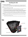
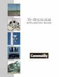
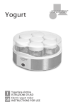
Distributed Design Series™
DA6 Architectural Loudspeaker
Installation and Operation Manual
DA6
Introduc on
Available in white or black and designed to mimic a ligh ng sconce, Community’s DA6 Architectural Surface-Mount
Loudspeaker is a high-performance product which doubles as an a rac ve architectural element that can be painted to match
a room décor.
The DA6 shares its innova ve coaxial transducer and crossover with other members of Community’s Distributed
Design Series loudspeaker family. This means Distributed Design Series ceiling loudspeakers, surface-mount loudspeakers,
pendant speakers and DA6 architectural loudspeakers can be used where needed in a restaurant, hotel lobby, conference
center or other facility while maintaining consistent voicing (sound quality) throughout. This also means Distributed Design
Series subwoofers, like the D10SUB (ceiling loudspeaker) or DS8SUB (surface mount loudspeaker) are excellent complements
to the DA6 when addi onal low-frequency support is desired. The DA6 is easy to install and can be used in 8-ohm mode or in
70-volt/100-volt mode for distributed systems.
Applica ons
Use one or two DA6s for music or voice in mee ng rooms, party rooms, o ces and other small spaces. Use mul ple
DA6s, in a distributed system, for restaurants and lounges, hotel lobbies and assembly rooms, classrooms and conference
rooms, museums, conven on centers, houses of worship, shopping malls, sports facility suites and concourses and other
public spaces.
Despite its compact size, Community’s DA6 is capable of rela vely high SPL levels (see Speci ca ons). Thus, in many
cases, DA6s may be used in moderate to high-noise environments like sports facility concourses, shopping malls or similar
public spaces.
Using the DA6 with Other D-Series Loudspeakers
Community’s D-Series includes ceiling loudspeakers, surface-mount loudspeakers, pendant loudspeakers and the DA6
architectural loudspeaker. All D-Series loudspeakers of a given size use the same innova ve coaxial transducer and crossover
network. That means the performance and voicing (sound quality) are uniform among all three loudspeaker styles allowing
designers to freely mix styles to match room décor or layout while maintaining uniform sound quality throughout a facility.
Wh ere to Insta ll t he DA6
In most installa ons, DA6s will be distributed along a wall some distance above the listeners’ heads, aiming down into
the room. The following chart and guidelines will help designers determine the best loca on and spacing for a par cular
installa on.
General Placement Guidelin es
Each DA6 creates a cone-shaped coverage pa ern approximately 100° wide that emanates from the face of the
loudspeaker poin ng downwards at an angle of 26° from the wall. When possible, locate the DA6s so that all listeners are
within the coverage pa ern of at least one DA6.
For the best voice intelligibility and in noisy or reverberant environments, overlap the coverage of adjacent DA6s by
20% to 30%. For low-level background music, it’s acceptable to install the DA6s farther apart. It may also be acceptable to
install the DA6s farther apart in voice systems when noise and reverbera on levels are low (see chart).
In high-ceiling spaces, such as sports facility concourses or airport wai ng areas, installing the DA6s near the ceiling
allows a wider spacing with good coverage (see chart). However, if the room is noisy or reverberant, consider installing the
DA6s at a lower height on the wall. Although this moun ng height will require a larger quan ty of DA6s, it will increase voice
intelligibility without the need for higher SPL levels.
CAUTION: Installa on of DA6 loudspeakers should only be performed by trained and
quali ed personnel. It is strongly recommended that a licensed and cer ed professional
structural engineer approve the moun ng. Severe injury and/or loss of life may occur if
this product is improperly installed.
Community DA6 Installa on/Opera on Manual — Page 2
DA6
How to U se the Spacing Chart
The DA6 Spacing Guide chart gives guidelines for DA6 spacing at di erent installa on heights. The shaded areas are
Community’s recommended spacing for a given installa on height and loudspeaker density. Follow these steps to use the
chart:
1) Determine the audience height. For example, a restaurant audience is probably seated (3.9 . / 1.2 m ear
height) whereas the audience in the lobby of a public building is probably standing (5.6 . / 1.7 m ear height).
2) Choose the desired DA6 installa on height in the Standing Audience or the Seated Audience column. The installa on
height is speci ed as the ver cal center line of the loudspeaker.
3) Follow the row to the Maximum E ec ve Distance column. For best results, this is the farthest distance any listener
should be located away from the DA6s.
4) Choose the desired DA6 horizontal spacing in the DA6 Horizontal Spacing Density column group as follows:
a)
Use the High Density column for noisy or reverberant spaces where voice intelligibility is cri cal.
b) Use the Medium Density column for less noisy spaces with some absorp on (like carpe ng and acous c ceiling les)
where voice intelligibility is important.
c)
Use the Low Density column for rela vely quiet spaces where the program is primarily background or foreground
music with occasional, non-cri cal voice paging.
d) Use the Very Low Density column for music and occasional, non-cri cal voice paging when it is acceptable to hear
some varia on in sound level from place to place in the room.
5) If there is a range of possible installa on heights, study the chart for di erent heights to determine the best combina on
of height and spacing for the installa on. Use Community’s recommended spacing (shaded area) whenever possible.
DA6 Spacing Guide (Along Wall or Boundary)
DA6 Vertical Height
STEP 1 & 2
Standing
Audience
(5.6 ft. / 1.7 m
ear height)
m
ft
2.6
8.5
9.5
2.9
3.2
10.5
3.5
11.5
3.8
12.5
13.5
4.1
4.4
14.5
4.7
15.5
5.0
16.5
17.5
5.3
Cover Distance
DA6 Horizontal Spacing Density
STEP 3
Seated
Maximum
Audience
Effective Distance
(3.9 ft. / 1.2 m
from Wall*
ear height)
m
m
ft
ft
3.4
2.1
7.0
11.0
3.7
8.0
2.4
12.0
4.0
2.7
9.0
13.0
4.8
3.0
10.0
15.6
5.6
3.4
11.0
18.2
6.4
12.0
3.7
20.8
7.1
4.0
13.0
23.4
7.6
4.3
14.0
25.0
7.6
4.6
15.0
25.0
7.6
16.0
4.9
25.0
STEP 4
High
±2.5dB)
ft
6.0
6.5
7.0
7.5
8.5
9.5
10.5
11.5
12.0
12.0
m
1.8
2.0
2.1
2.3
2.6
2.9
3.2
3.5
3.7
3.7
Medium
±3dB)
ft
8.5
9.2
9.9
10.6
12.0
13.4
14.8
16.3
17.0
17.0
Low
±3.5dB)
m
2.6
2.8
3.0
3.2
3.7
4.1
4.5
5.0
5.2
5.2
ft
12.0
13.0
14.0
15.0
17.0
19.0
21.0
23.0
24.0
24.0
m
3.7
4.0
4.3
4.6
5.2
5.8
6.4
7.0
7.3
7.3
Very Low
±4dB)
ft
17.0
18.4
19.8
21.2
24.0
26.9
29.7
32.5
33.9
33.9
m
5.2
5.6
6.0
6.5
7.3
8.2
9.1
9.9
10.3
10.3
* Measured perpendicular from the wall surface, not the flight distance from the loudspeaker to listener
Safe Moun ng
Select a loca on for the DA6 that allows it to be securely mounted to a building structural member. Do not mount
the DA6 to a drywall or plaster wall unless the DA6 moun ng plate is also securely fastened to a building structural
member.
The DA6 moun ng plate has holes that match standard 1 or 2-gang electrical outlet boxes. This is a convenient way
to meet local codes and bring concealed wiring to the DA6 but, by itself, moun ng to an electrical box is not usually a
su cient structural moun ng system. When moun ng the DA6 to an electrical box, use the addi onal moun ng holes in the
DA6 moun ng plate to securely fasten the DA6 to a building structural member.
Community DA6 Installa on/Opera on Manual — Page 3
DA6
Installing the DA6
Wir ing the Instal la on
Bring the speaker cable to each DA6 loca on before moun ng the DA6 to the wall. Use 16-gauge or larger stranded
speaker cable for best results. Leave approximately 6” (15 cm) of speaker cable coming out of the wall at each loca on for
connec on to the DA6. When the DA6 is mounted to the wall, this speaker cable will be pushed back into the wall or electrical
box.
Moun ng and Wiring the DA6
Bring the speaker cable through the center hole in the DA6 moun ng plate (Figure 1). Then, securely fasten the DA6
moun ng plate to the wall and electrical box (if used). Con rm safe moun ng to a building structural member.
Locate and examine the Euro socket on the rear of the DA6. The inside pair of connec ons are for the loudspeaker.
The outside pair of connec ons are paralleled to the inside pair and are provided for convenient daisy-chaining to the next DA6
in a distributed system. Note the le pair of connec ons is posi ve or “+” and the right pair of connec ons is nega ve or “-“.
Strip about 1/4” (6 mm) from each speaker wire and a ach them to the provided Euro connector. Correct polarity is
cri cal for proper opera on so con rm that the + wire is connected to posi on #2 and the - wire is connected to posi on #3 on
the Euro connector. If the next loudspeaker is to be connected in daisy-chain fashion, connect its wires to posi on #1 (+) and
posi on #4 (-).
Use a straight-blade or Phillips screwdriver to set the DA6 tap switch to the posi on chosen by the system designer.
This must be done before moun ng the DA6 to the wall.
Plug the Euro connector into the Euro socket on the rear of the DA6. The connector should seat rmly in the socket.
Figure 1
Euro Socket
Moun ng
Plate
Tap Switch
Euro Connector
Community DA6 Installa on/Opera on Manual — Page 4
DA6
To mount the DA6 to the wall, slip it over the moun ng plate and slide the DA6 downwards to snap it into place
(Figure 2). This completes the moun ng and wiring process.
Figure 2
Figure 3
Figure 4
Uninstalling the DA6
Should it become necessary to remove the DA6 from its moun ng loca on, the loudspeaker locking mechanism
must be released via the small hole on the bo om of the DA6 (Figure 4). A speci c tool is not provided for this purpose. Any
simple tool, such as an Allen key or screwdriver, can be used. The tool should be at least 4” (102mm) long and no more than
0.2” (5mm) in diameter (a standard length #1 Phillips Screwdriver is usually an adequate size). Push upwards and hold to
disengage the spring-loaded locking mechanism. While con nuing to push upwards and holding the locking mechanism in
the disengaged posi on, carefully li the DA6 straight up (about 1/2” inch) and o of the moun ng bracket. Once clear of
the bracket, the DA6 can be removed from the wall, the Euro connector disconnected, and the removal tool may be
withdrawn.
Community DA6 Installa on/Opera on Manual — Page 5
DA6
Outdoor Usage
The Community DA6 is inherently weather-resistant and may be installed outdoors. To protect the connectors and
wiring from corrosion, apply a small amount of silicon seal to the speaker wires as they enter the Euro connector a er making
the connec ons.
Pain ng the DA6
Ty p e o f P a i n t
These loudspeakers’ ABS plas c cabinets accept almost any type of latex or enamel (oil based) paint. We recommend
applica on of two coats. Note however that pain ng the grille requires spray pain ng.
Pain n g Process
Follow this procedure to obtain the best results:
1.
Remove the grille and carefully remove the grille foam from the grille (the foam cannot be painted). Discard the original
grille foam, it cannot be re-used. Order replacement DA6 grille foam from Community.
2.
Clean the grille assembly and the loudspeaker cabinet by rubbing them with a lightly dampened cloth. Do not use
abrasives such as sandpaper or steel wool.
Cau on: NEVER use abrasives, gasoline, kerosene, acetone, methyl ethyl ketone (MEK), paint thinner, harsh
detergents or other chemicals. These chemicals may permanently damage the nish. Some are also toxic and
highly ammable.
3.
Mask the loudspeakers so that the surrounds, cones and center areas will not receive any paint. We advise against using
conven onal masking tape and NEVER use duct tape in this applica on; these kinds of tape generally leave adhesive
residue that can be di cult to remove and that may actually cause damage. Painters tape is best.
4.
er cleaning, apply two or more thin coats of either latex or oil-based paints. Latex paint will adhere be er if an oilbased primer is used rst. Apply the paint with a roller or brush, or spray it on, except as noted below.
5.
Use ONLY spray paint on the grille assembly; using a roller or brush to paint the grille is apt to cause its metal perforated
holes to become clogged with paint. The grille should be painted separately, when it is not in place on the loudspeaker.
6.
ach the replacement grille foam to the grille using an aerosol spray adhesive. For best results it may be necessary to
spray adhesive on both the grille and foam. Spray adhesive very lightly on the foam to prevent clogging the pores. The
replacement foam will be oversized. It must be applied to the grille, then trimmed to size once in place.
Community DA6 Installa on/Opera on Manual — Page 6
DA6
Warranty and Service Informa on
.
TRANSFERABLE WARRANTY “(LIMITED)” VALID IN THE USA ONLY
The Distributed Design DA6 Loudspeaker Systems are designed and backed by Community Professional Loudspeakers.
For complete warranty informa on within the USA please refer to the Warranty Card enclosed with the product. Please call
610-876-3400 to locate your nearest Authorized Field Service Sta on. For Factory Service call 610-876-3400. You must obtain
a Return Authoriza on (R/A) number prior to the return of your product for factory service.
WARRANTY INFORMATION AND SERVICE
FOR COUNTRIES OTHER TH AN THE USA
To obtain speci c warranty informa on and available service loca ons for countries other than the United States of
America, contact the authorized Community Distributor for your speci c country or region.
SH IP PING D AMAG E
If the product is damaged during transit you must le a damage claim directly with the freight company. Be sure to
save the carton and packing materials, as damage claims can be denied if these materials are not retained. If evidence of
physical damage exists upon arrival, be cau ous before signing the delivery acceptance receipt. O en, the ne print will
waive your right to le a claim for damage or loss a er you sign it. Make sure that the number of cartons shown on the freight
documents have actually been delivered.
FIND THE LATEST ONLINE
Visit Community at
informa on.
p://www.communitypro.com for the latest version of this manual and the most recent product
E C S TAT E M E N T O F C O N F O R M I T Y
This document con rms that the range of products of Community Professional Loudspeakers bearing the CE label meets
all of the requirements in the EMC direc ve 89/336/EEC laid down by the Member States Council for adjustment of legal
requirements. Furthermore, the products comply with the rules and regula ons referring to the electromagne c
compa bility of devices from 30-August-1995.
The Community Professional Loudspeaker products bearing the CE label comply with the following harmonized or
na onal standards: DIN EN 55013:08-1991, DIN EN 55020:05-1995, DIN EN 55082-1:03-1993
The authorized declara on and compa bility cer
The responsible manufacturer is the company:
ca on resides with the manufacturer and can be viewed upon request.
Community Light & Sound
333 East 5th Street
Chester, PA 19013 USA
TEL: 1-610 876-3400 / FAX: 1-610 874-0190
Chester, PA USA
September 2012
Community DA6 Installa on/Opera on Manual — Page 7
Distributed Design Series™
DA6 SPECIFICATIONS
Loudspeaker Type:
Frequency Range
(Half-Space):
Nominal -6dB Beamwidth:
Crossover Frequency:
Sensitivity (1w/1m):
Nominal Impedance:
Power Capacity:
Max SPL (1m Free Space):
Autoformer Taps--70V:
100V:
Enclosure Type:
Environmental:
Colors:
Mounting System:
6.5-inch, two-way, full-range, coaxial, surface mount loudspeaker,
8 ohm or 70V/100V operation
80 Hz to 20 kHz (-3 dB)
65 Hz to 22 kHz (-10 dB)
115° conical (1 kHz to 6 kHz)
1.2 kHz
93 dB (125 Hz to 12.5 kHz) half space
91 dB (250 Hz to 4 kHz) half space
8 ohms
RMS 100W (28.3V)
Program 250W (44.7V)
Peak 400W (56.6V)
113 dB (119 dB Peak) 8 ohm tap
60W, 30W, 15W, 7.5W and low impedance
60W, 30W, 15W and low impedance
High-Strength, Impact-Resistant, Injection-Molded ABS Plastic (Paintable)
IP55 (per IEC529), designed to Mil Spec 810 Standards
White or Black (Paintable)
Included flush-mount wall bracket
(fits 1 or 2-gang electrical box - not included)
Dimensions—Height:
Width:
Depth:
11.2 inches (284.2 mm)
15.3 inches (388.7 mm)
8.3 inches (211.5 mm)
Loudspeaker Weight:
11.9 lbs (5.4 kg)
Shipping Weight:
17.7 lbs (8.0 kg)
Community strives to improve its products on a continual basis. Specifications are therefore subject to change without notice.
Community Professional Loudspeakers
333 East Fi h Street
Chester, PA 19013-4511 USA
TEL: 1-(610) 876-3400 FAX: 1-(610) 874-0190
www.communitypro.com
© 2012 All Rights Reserved
13SEPT2012