1
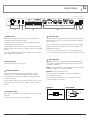
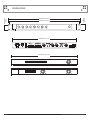
REAR PANEL
CLASS 2 WIRING
POWER
1
OUTPUT 2
OUTPUT 3
2
VCA 1
CLASS 2 WIRING
0VDC
OUTPUT 4
VCA 2
+24VDC
VCA 3
VCA 4
4 channel model shown here
Made in The Philippines
OUTPUT 1
INPUT 4
LEVEL 4
LEVEL 3
3
1 Mains Input
Mains input is via a 3-pin IEC socket. A mains cable to suit your region is
provided with your Australian Monitor amplifier.
The amplifier may be isolated from the mains supply with the mains switch
provided. All models are internally fused.
The AMD2100P model operates from a wide range supply of 90 to 264VAC
while all remaining models are internally configured for either 115V or 230VAC
operation.
Please contact Australian Monitor should your amplifier need to be changed
from its shipped voltage configuration.
2 Battery Input
24 VDC input for emergency power systems.
INPUT 3
INPUT 2
LEVEL 2
LEVEL 1
INPUT 1
4
ETHERNET
5
6
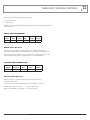
5 Ethernet Port
The Ethernet port provides PC connectivity for use with the supplied software
application and also remote control and status monitoring for use with third
party control systems.
A pair of LED indicators provide link activity and link speed status feedback.
Modules for both Crestron and AMX control systems are available from the
Australian Monitor web site.
For users of other control systems, please refer to the Third Party Control
Protocol section later in this document for a detailed description of the protocol.
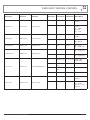
6 Logic Controls
VCA: Remote VCA level controls per channel. An Australian Monitor RC1
remote panel or any 500 kohm potentiometer may be connected between
the GND pin and a VCA pin.
GRN: Low Power Standby Mode. The amplifier will enter low power standby
mode when the GRN pin is connected to the GND pin.
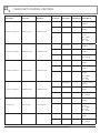
3 Amplifier Outputs
Amplifier outputs are terminated on 5.08” pitch removable connectors.
Mating connectors are provided with your Australian Monitor amplifier.
Each amplifier channel output provides 4 Ohm (voice coil), 70V and 100V
(constant voltage) outputs.
RS232: Serial port for third party control.
Modules for both Crestron and AMX control systems are available from
the Australian Monitor web site.
Refer to the Third Party Control Protocol section later in this document
for detailed description of the protocol.
For each amplifier channel, only one output type should be used. You may use
a different output type for each channel ie. 4 Ohms on Channel 1, 100V on
Channel 2.
Ethernet
Female XLR
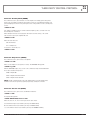
4 Amplifier Inputs
Balanced line level XLR inputs. The pin configurations are as per the diagram
to the right.
Input level controls are provided for each input channel.
AMD SERIES INSTALLATION AND OPERATION MANUAL
LINK/ACTIVITY
ON: Link Activity
FLASH: Activity
SPEED
OFF: 10Mbps
ON: 100Mbps
PIN 2
HOT
(+)
PIN 1
GND
PIN 3
COLD
(–)
PAGE 5