1
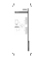
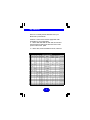
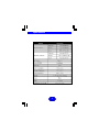
©1999 ATEN Technology, Inc. All Rights Reserved. Microsoft and Windows 98 are registered trademarks of Microsoft Corporation. IBM is a registered trademark of International Business Machines, Inc. Macintosh, G3/G4 and iMac are registered trademarks of Apple Computer, Inc. ATEN is a registered trademark of ATEN Technology, Inc. IOGEAR is a registered trademark of ATEN Technology, Inc. ATEN Technology makes no warranty of any kind with regards to the information presented in this document. All information furnished here is for informational purposes only and is subject to change without notice. ATEN Technology assumes no responsibility for any inaccuracies or errors that may appear in this document. Packing List The complete IOGEAR MiniView package consists of: TM • • • • One MiniView KVM switch Two or four sets of custom cables, depending on the model. G-CS12 comes with two cables while G-CS14 comes with four. One User Manual One Quick-Start Setup Guide TM Note: If your computers use AT keyboard connectors, please contact us for a free set of PS/2-AT adapters. Please check to make sure that all components are included and nothing is damaged. If you discover a problem, please contact your dealer. Before connecting your MiniView , read the manual thoroughly and follow the installation and operation procedures carefully in order to prevent any damage to the unit and/or any devices it connects to. Packing List TM Contents Introduction ……...…………...……... 01 Features ………………………………... 02 Hardware Requirements …………… 03 Installation …………………..………… 04 Operation ………………………….……. 06 Manual Port Selection HotKey Port Selection …………….………. 07 Auto Scan Mode ………………………….... 08 Next/Last Mode ……………………….……. 09 Appendix A ……………………………… 10 Specifications Appendix B ……………………………… 11 Troubleshooting Appendix C ………………………………. 12 Contacting IOGEAR Appendix D ………………………………. Contents Radio Interference / Warranty 13 Introduction Thank you for purchasing one of the smallest and most feature-rich KVM switches on the market. IOGEAR’s KVM switches are first-rate connectivity accessories designed to help reduce the frustration of managing multiple computer systems. With the MiniView series by IOGEAR, you can access multiple computers from a single console (keyboard, mouse and monitor). The MiniView provides two convenient methods to access connected computers. Change ports easily via the push button selection switch located on the unit’s side panel, or by entering Hot Key combinations from the keyboard. Setup is fast and easy; plugging cables into their appropriate ports is all that is entailed. There is no software to configure, no installation routines and no incompatibility problems. Since the MiniView intercepts keyboard input directly, it works on any PS/2 compatible hardware platform and with all operating systems. There is no better way to save time and money than with a MiniView . By allowing a single console to manage the attached computers, the MiniView eliminates the expense of purchasing a separate keyboard, monitor and mouse for each PC. Additionally, these switches save all the extra space multiple consoles would take up, and eliminate the inconvenience and wasted effort involved in constantly having to move from one PC to the other. TM TM TM TM We hope you enjoy using your MiniView KVM switch, yet another first-rate connectivity solution from IOGEAR. TM Introduction TM 1 Features Supports Microsoft IntelliMouse, Logitech MouseMan+, FirstMouse+, IBM Scroll Point Mouse and many others Keyboard and mouse emulation for error free PC booting Hot pluggable – add or remove connected PCs without powering off the MiniView TM Full Plug-n-Play monitor support Caps Lock, Num Lock and Scroll Lock status is saved and restored when switching ports Supports video resolutions up to 1920 x 1440 Easy installation - no software required Built-in Auto Scan Mode Uses standard connectors to connect PC’s Easy to operate - PC selection via push button or Hot Keys Compatible with all operating platforms LED display for easy status monitoring Saves time, space, power and equipment costs Power-free design – the MiniView draws power from the attached computers Features TM 2 Hardware Requirements Console One VGA, SVGA, or Multisync monitor capable of the highest resolution that you will be using on any PC in the installation One PS/2 mouse One PS/2 keyboard or One AT keyboard w/ a PS/2 keyboard adapter PC The following equipment must be installed on each PC that is to be connected to the system: One VGA, SVGA or Multisync video card One PS/2 mouse port One PS/2 or AT keyboard port * See the note under Cables in the next section. Note: The keyboard and mouse cables have PS/2 connectors at each end. If your PC uses a standard AT style keyboard socket, you will need an AT-PS/2 keyboard adapter in order to plug the cable into the PC’s keyboard port. Be aware, however, that because of the wiring and pin assignments, attempting to use standard extender cables with adapters at both ends will not work. You cannot use an AT-PS/2 adapter at the end that plugs into the MiniViewTM. The MiniViewTM supports PS/2 mice only. Please note that PS/2-serial converters will not afford proper functionality with your MiniViewTM KVM switch. Require... ... Hardware Require Cables Although it’s possible to use standard extender cables to connect the PCs to the MiniViewTM, for optimum signal integrity and to simplify the layout we strongly recommend that you use the high quality custom cables that are provided as part of the package. 3 Installation Installation Before you begin, make sure that the computers you’re going to connect to the MiniViewTM are turned off. 4 1 Plug the monitor, keyboard, and mouse into the console port connectors of the MiniViewTM unit. 2 Use the extender cables (as described in the Hardware Requirements and Unpacking sections) to connect the monitor, keyboard and mouse ports of the PCs to the MiniViewTM CPU ports, as shown in the diagram to the right. If your PC uses an AT style connector for the keyboard port, connect a PS/2-AT adapter to the end of the cable that will connect to the PC. If you don’t have a PS/2-AT adapter available, please contact us and we’ll be happy to provide one at no extra charge. 3 Turn on the power to the connected PCs. Installation Installation... Installation... 5 Operation Controlling the PCs in your MiniViewTM configuration from a single console couldn’t be easier. Two port selection methods provide instant access to any attached PC: Manual Port Selection Hot Key Port Selection Note: When powering-on, the MiniViewTM switches to port 1 by default. If the PC attached to port 1 is inactive, the monitor will be blank so it may appear as if the unit is not functioning. This is not the case. Simply use one of the port selection methods described below to switch to the active PC on a different port. Operation Manual Port Selection With manual port selection, you simply press the Port Selection button on the side panel of the MiniViewTM to switch between computers. The selected LED on the top panel will light up to indicate which port is active. 6 Operation... Operation... Hot Key Port Selection Hot Key navigation allows you to select the active PC directly from the keyboard, instead of having to manually select it by pressing the Port Selection button. The MiniView provides several Hot Key navigation features: TM ♦ ♦ ♦ Active port selection Auto Scan Mode Last/Next Mode Note: For Hot Key operations that begin by pressing and releasing the Ctrl + Alt + Shift combination, please remember that the keys must all be on the same side of the keyboard (i.e. Left Ctrl + Left Alt + Left Shift or Right Ctrl + Right Alt + Right Shift). 2-Port MiniViewTM Press and release the Left Ctrl or Right Ctrl key twice. Note: The combination must be on the same side of the keyboard (Left Ctrl + Left Ctrl or Right Ctrl + Right Ctrl) 4-Port MiniViewTM 1. Press and release Ctrl + Alt + Shift 2. Key in the appropriate Port ID (1, 2, etc.) 3. Press [Enter] Operation Selecting the Active Port: Each CPU port is assigned a numeric ID (CPU1, CPU2, etc.). You access the PCattached to a port by specifying the Port ID as part of the Hot Key combination as follows: 7 Operation... Auto Scan Mode: The Auto Scan feature automatically switches between the connected PCs at regular intervals so that you can monitor their activity without having to take the trouble of switching yourself. To invoke Auto Scan Mode, key in the following Hot Key combination: 2-Port MiniViewTM: Press and release the Left Shift key, then press and release the Right Shift key (Left Shift + Right Shift). Once scanning begins, it continues until you press the [Spacebar] to exit Auto Scan Mode. The port that was active at the time scanning stopped remains active. 4-Port MiniViewTM: 1 Press and release Ctrl + Alt + Shift 2 Press and release 0 (zero) 3 Press [Enter] Operation Once scanning begins, it continues until you press the [Spacebar] to exit Auto Scan Mode. The port that was currently active at the time scanning stopped remains active. 8 Note: While Auto Scan Mode is in effect, none of the other keyboard keys will function. You must exit Auto Scan Mode by pressing the [Spacebar] in order to use the console for anything else. Operation... Operation... Next/Last Mode: The Last/Next feature is provided to enable you to quickly switch back and forth between computers in order to monitor them manually, instead of using Auto Scan Mode. This method lets you monitor a particular computer for as long or as little as you like - as opposed to Auto Scan Mode, which switches after a fixed interval. To invoke Last/Next Mode, key in the following Hot Key combination: 1. Press and release Ctrl + Alt + Shift 2. Press and release 9 3. Press [Enter] Operation Once Last/Next Mode is active, pressing the Left Shift key (LShift) switches to the previous computer (from the currently active one) while pressing RShift switches to the next computer in the configuration. 9 Appendix A Specifications: Port Selection Hot Keys /Port Selection Button Keyboard: PS/2 & AT Mouse: PS/2 Keyboard: 6-pin mini-DIN (F) Emulation LEDs Console Connectors PC Connectors Port-Selected Mouse: 6-pin mini-DIN (F) Monitor: HDB-15 VGA (F) Keyboard: 6-pin mini-DIN (F) Mouse: 6-pin mini-DIN (F) Monitor: HDB-15 VGA (F) Video Resolution Max: 1920 x 1440, DDC2B AutoScan Interval L E D A c tiv ity Power Consumption O ff Housing 3 seconds O n ( s t eTemperature ady) Operating M e a n in g DC 5V 20mA Port is not selected Plastic Port is not connected to an 5°C ~ 40°C a c t i v e P C -20°C ~ 60°CP o r t i s c o n n e c t e d t o a n active PC and is being o f f , e q 0u ~a l80% l y ) RH, Noncondensing accessed in Auto Scan M ode G-CS12: 4.9 ounces Weight Port is connected to an F l a s h i n g ( l o n g o n ; s h o rG-CS14: t o f f ) 8.1aounces ctive PC and is being accesed in Next/Last M ode G-CS12: 4.0" x 3.4" x 1.1" Dimensions (L x W x H) G-CS14: 6.7" x 3.4" x 1.1" Storage Temperature Appendix A Flashing (on & Humidity 10 LED Display LED Activity Meaning Off Port is not selected On (steady) Port is selected Flashing (on & off, equally) Port is connected to an active PC and is being accessed in Auto Scan Mode Flashing (long on; short off) Port is connected to an active PC and is being accesed in Next/Last Mode Appendix B Troubleshooting: Note: If you are experiencing any erratic behavior from your MiniViewTM, first make sure there are no problems with the cables and that they are all properly connecetd. Problem The keyboard is not responding. Possible Cause Action The keyboard needs to be reset. Disconnect the keyboard from the MiniViewTM, wait a few seconds and plug it back in. The MiniViewTM needs to be reset. Shut down the computers and disconnect the keyboard from the MiniViewTM. Power off the MiniViewTM, wait a few seconds, reconnect the keyboard and power The mouse is not responding. Video is distorted or non-existant. The mouse needs to be reset. Disconnect the mouse from the MiniViewTM then reconnect it. The MiniViewTM needs to be reset. Shut down the computers and the MiniViewTM. Wait a few seconds then power everything on. The mouse is in an unsupported mode. The MiniViewTM does not support some combo mice (with extra buttons and wheels), which can be used as either a PS/2 or serial mouse. If the mouse is in serial mode, switch the mouse to PS/2 mode if you wish to use the extra buttons or wheel. If the problem persists, try using a different mouse or a different mouse driver. A serial mouse or serial mouse port is included in the system configuration The MiniViewTM G-CS12 and G-CS14 were designed to operate only with PS/2 mice and PS/2 computers. PS/2-to-serial adapters will not afford proper functionality when used with the MiniViewTM. Please make sure all computers and mice connected in your configuration are using 6-pin mini-Din (PS/2) connectors. Cable quality is not adequate. We strongly recommend that you use highquality KVM cables, such as the ones included in your IOGEAR MiniViewTM package. Using inadequate cables can result in video distortion. Appendix B MiniView TM is in Auto Press the [spacebar] key to exit Auto Scan or Next/Last Mode. Scan or Next/Last Mode 11 Appendix C Contacting IOGEAR In the event that your MiniViewTM fails to function properly, or you wish to contact us for any other reason, here are a few ways to contact us. IOGEAR 16560 Aston Street Irvine, CA 92606 Phone: (949) 250-1260 Toll Free: (888) 999-2836 Fax: (949) 250-1262 Appendix C www.iogear.com [email protected] 12 Appendix D Radio & TV Interference Statement This equipment has been tested and found to comply within the limits for a Class B digital device, pursuant to Part 15 of the FCC Rules. These limits are designed to provide reasonable protection against harmful interference in a residential installation. This equipment generates, uses and can radiate radio frequency energy and if not installed and used in accordance with the instructions, may cause harmful interference to radio communications. There is no guarantee, however, that interference will not occur in a particular installation. Limited Warranty IN NO EVENT SHALL THE DIRECT VENDOR’S LIABILITY FOR DIRECT, INDIRECT, SPECIAL, INCIDENTAL OR CONSEQUENTIAL DAMAGES RESULTING FROM THE USE OF THE PRODUCT, DISK OR IT’S DOCUMENTATION EXCEED THE PRICE PAID FOR THE PRODUCT. The direct vendor also reserves the right to revise or update the device or documentation without obligation to notify any individual or entity of such revisions, or updates. For further inquiries please contact your direct vendor. Appendix D The direct vendor makes no warranty or representation, expressed, implied, or statutory with respect to the contents or use of this documentation, and especially disclaims it’s quality, performance, merchantability, or fitness for any particular purpose. 13 IOGEAR 16560 Aston Street Irvine, CA 92606 Phone: (949) 250-1260 Toll Free: (888) 999-2836 Fax: (949) 250-1262 www.iogear.com [email protected] IOGEAR 16560 Aston Street Irvine, CA 92606 Phone: (949) 250-1260 Toll Free: (888) 999-2836 Fax: (949) 250-1262 www.iogear.com [email protected] ©1999 ATEN Technology, Inc. All Rights Reserved. Microsoft and Windows 98 are registered trademarks of Microsoft Corporation. IBM is a registered trademark of International Business Machines, Inc. Macintosh, G3/G4 and iMac are registered trademarks of Apple Computer, Inc. ATEN is a registered trademark of ATEN Technology, Inc. IOGEAR is a registered trademark of ATEN Technology, Inc. ATEN Technology makes no warranty of any kind with regards to the information presented in this document. All information furnished here is for informational purposes only and is subject to change without notice. ATEN Technology assumes no responsibility for any inaccuracies or errors that may appear in this document. Package Contents This IOGEAR package contains: G-CV160 Mac – PS/2 Adapter ADB Patch Cable Mac Video Patch Cable User Manual & Setup Guide Product Registration / Warranty Card Please check to make sure that all components are included and nothing is damaged. If you discover a problem, please contact your dealer. Before connecting your MiniView , read the manual thoroughly and follow the installation and operation procedures carefully in order to prevent any damage to the unit and/or any devices it connects to. TM Contents Introduction ……...…………...……... 01 Features / Sys. Requirements …… 02 Installation ……………………..……… 03 KVM Setup ………………………………….. Non-KVM Setup ………...………….………. 04 Connection Diagrams …………………….... 05 Dip Switches ….………………………… 06 Video Keyboard & Mouse 07 Mac Key Assignments …………….… 08 Specifications …………………….….… 09 Radio Interference / Warranty ...… 10 Contacting IOGEAR ..…………………. 11 Introduction Thank you for purchasing IOGEAR’s MiniViewTM Mac Adapter, a Macintosh-PS/2 converter that allows seamless integration of a Macintosh computer into your existing KVM configuration. Our Mac Adapter is fully compatible with older Macintosh systems, the new iMac, G3 and G4. Full Macintosh keyboard functionality is supported on any PS/2 keyboard, while a second ADB port allows your existing ADB devices to be used with the Mac. Although this unit is fully compatible with our PS/2 KVM switches, it can also be used as a stand-alone Mac-PS/2 converter. We hope you enjoy using your new Macintosh Adapter – yet another first-rate connectivity solution from IOGEAR. 1 Features / System Requirements Features Converts from ADB and DB-15 to PS/2 and HDB-15 Allows a Macintosh system to be incorporated into your KVM setup. Secondary ADB port provides support for additional Macintosh accessories. Full Mac functionality supported on a PS/2 keyboard No software required. Patented VSE technology supports ultra high quality video at resolutions up to 1920 x 1440. Save time, space and money. 3 Year Limited Warranty. System Requirements 1) 2) 3) 4) Macintosh computer with: ADB connectors for the mouse & keyboard DB-15 connectors for the video (standard Mac Video) A PS/2 mouse A PS/2 or AT keyboard A VGA, SVGA or MultiSync monitor 2 Installation Installation in a KVM setup: Before installing your G-CV160, please make sure your Macintosh is powered OFF. 1) Connect the PC keyboard and mouse ports on the G-CV160 to one of the PC ports on your KVM switch. Be sure the keyboard port on the KVM switch is connected to the keyboard port on the G-CV160, and the same is true for the mouse ports. 2) If you have an older Macintosh with DB-15 (Mac video) connectors, connect the PC video port on the G-CV160 to the corresponding video port on your KVM switch. If you're connecting the G-CV160 to a new G3, G4 or other Macintosh with HDB-15 video connectors, you can bypass the video portion of the G-CV160 and connect the video port on your KVM switch directly to the Mac. 3) Connect the Mac ports on the G-CV160 to your Macintosh computer. 4) If you have any extra ADB devices (beside the typical mouse and keyboard), connect them to the 2nd ADB port on the side of the G-CV160. 3 Installation Before installing your G-CV160, please make sure your Macintosh is powered OFF. Installation without a KVM switch: 1. Connect your PS/2 keyboard and mouse to the PC ports on the G-CV160. 2. If you have an older Macintosh with DB-15 (Mac video) connectors, connect your monitor to the PC video port on the GCV160. If you’re connecting the G-CV160 to a new G3, G4 or other Macintosh with HDB-15 video connectors, you can bypass the video portion of the G-CV160 and connect the monitor switch directly to your Mac. 3. Connect the Mac ports on the G-CV160 to your Macintosh computer. 4. If you have any extra ADB devices (besides the typical mouse and keyboard), connect them to the 2nd ADB port on the side of the G-CV160. 4 Installation 5 Dip Switches Note: Do not modify the DIP Switches when your Macintosh is powered-ON. Switches 1-6 are used to set the appropriate video properties for your configuration. *1 – When SW5 and SW6 are both ON, the VGA and SVGA resolution settings are selected in the monitor portion of the control panel. *2 – When SW1, SW5 and SW6 are all ON, VGA and 6 Dip Switches Switch 7 is used to toggle between a standard 101 and 104 key keyboard. Switch 8 toggles the mouse between high and normal speed settings. 7 Mac Key Assignments 8 Specifications 9 Radio Interference / Limited Warranty Radio & TV Interference Statement This equipment has been tested and found to comply within the limits for a Class B digital device, pursuant to Part 15 of the FCC Rules. These limits are designed to provide reasonable protection against harmful interference in a residential installation. This equipment generates, uses and can radiate radio frequency energy and if not installed and used in accordance with the instructions, may cause harmful interference to radio communications. There is no guarantee, however, that interference will not occur in a particular installation. Limited Warranty IN NO EVENT SHALL THE DIRECT VENDOR’S LIABILITY FOR DIRECT, INDIRECT, SPECIAL, INCIDENTAL OR CONSEQUENTIAL DAMAGES RESULTING FROM THE USE OF THE PRODUCT, DISK OR IT’S DOCUMENTATION EXCEED THE PRICE PAID FOR THE PRODUCT. The direct vendor makes no warranty or representation, expressed, implied, or statutory with respect to the contents or use of this documentation, and especially disclaims it’s quality, performance, merchantability, or fitness for any particular purpose. The direct vendor also reserves the right to revise or update the device or documentation without obligation to 10 Contacting IOGEAR In the event that your MiniViewTM fails to function properly, or you wish to contact us for any other reason, here are a few ways to contact us. IOGEAR 16560 Aston Street Irvine, CA 92606 Phone: (949) 250-1260 Toll Free: (888) 999-2836 Fax: (949) 250-1262 www.iogear.com [email protected] 11