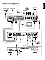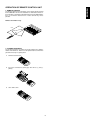
1
ENGLISH
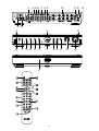
EXPLANATION OF THE REAR
PANEL TERMINALS
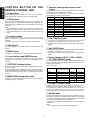
FRONT PANEL
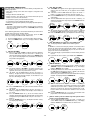
A STANDBY/power button and indicator
Press to turn power ON and press again to switch to STANDBY mode.
The indicator lights GREEN when power is ON, and lights RED when in
STANDBY mode. The indicator lights AMBER when the timer program is
set during STANDBY mode.
CONNECTORS AND CONTROLS ON THE
MAIN UNIT
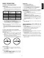
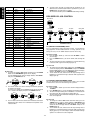
q Terminal for FM antenna, 75 ohms
B Infrared sensor
For connecting an external FM antenna with a coaxial cable, or for
connecting a cable network.
The infrared signal from the remote control unit enters the unit through
this window. To operate the unit with the receiver door open, point the
remote control infrared signal transmitter toward this window.
w Terminals for AM antenna and
Grounding
C PHONES jack
To connect the supplied AM loop antenna, use the terminals marked
“AM” and “GND”.
In areas where the AM loop antenna gives unsatisfactory results, it is
recommended that the receiver be connected to an outdoor antenna.
Use the terminal marked ‘AM’ for this. A grounding lead can be connected
to the terminal marked ‘GND’ to further reduce interference. In this case,
it must be connected together with the supplied loop antenna.
This jack is used to connect dynamic type headphones, which provide a
wide range sound. When the headphones are connected to this jack, the
speaker sound is turned off, and output sound is changed to stereo mode.
Note:
If the headphones are connected to this jack, the receiver door
does not close even if you press the door CLOSE button or the unit
is in standby mode.
The DV2100’s 5.1ch mode is changed to 2ch (STEREO) mode
automatically.
e DVD input jacks
Connect to the audio/video output jacks of the DVD player (DV2100).
When the DV2100 is connected with the SYSTEM bus connection, the
SURROUND L/R, CENTER, and SUBWOOFER jacks should be
connected to these DVD input jacks. The FRONT L/R jacks should be
connected to the SYSTEM OUT jacks y.
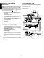
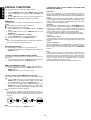
D SURROUND button
Press to change surround mode. The mode changes as follows.
When in DVD mode:
STEREO → 5.1CH → CS Movie →
CS Music → STEREO
When in other mode: STEREO → CS Movie → CS Music → STEREO
r LD/VCD input jacks
Note:
Surround mode does not change while listening to AM broadcasts.
Press this button to cancel the AM beat noise while receiving the
AM broadcasts.
Connect to the audio/video output jacks of the LD/VCD player.
t TV input jacks
Connect to the audio/video output jacks of the TV set.
E TUNER button
y AUX input jacks (SYSTEM OUT jacks)
Press to select FM or AM tuner when another source is selected and
select the JOG operation for TUNER selection. Use this button to select
the JOG operation for a scan of frequency, preset memory or RDS mode.
The TUNER button changes modes as below.
FREQUENCY mode: To scan tuning by frequency by JOG control.
PRESET mode: To scan tunings in the preset memory by JOG
control.
RDS mode: To select RDS control (PTY, TP, TA, and EON
SEEK) by JOG control.
Please refer to page 10 for tuner operations.
Connect to the audio/video output jacks of other equipment.
Connect to the SYSTEM AUDIO IN jacks of the Marantz AV system
(DR2100, DV2100) when the SYSTEM bus connection is used.
u VCR input/output jacks
Connect the IN jack to the audio/video output jack of your main VCR and
connect the OUT jack to the audio/video input jack of the VCR.
i MONITOR OUT jack
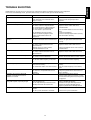
F BAND button
Connect to the video input jack of your TV.
Press to change the reception band to FM or MW.
o 6ch output jacks
G MEMORY button
These jacks are supplied for pre-amplifier output signals, and are used
to connect to external power amplifiers. (If necessary)
Press to set the preset memory of the tuner, clock time or timer program.
Please refer to the tuner and timer operations.
!0 SPEAKER SYSTEM terminals
Connect the front L/R, center, surround L/R speaker leads, observing
the + and - polarity of the leads and terminals.
!1 REMOTE CONTROL jacks
Connect to a component equipped with remote control jacks. (Refer to
page 3.)
!2 System control switch
This switch selects the system operation mode. Set to SYSTEM position
when the unit is being used in combination with a CD-R (DR2100) or
DVD (DV2100). If your component is not capable of system connection,
set this switch to INT position.
!3 AC inlet
Connect the provided power cord, and after all connections are finished,
connect the AC plug to a house hold outlet (AC 230V).
6