1
®
NetFRAME LV2000
Server System User’s Guide
MAS001523-00, 10/97
Copyright and Trademarks
The information in this document is subject to change without notice.
Micron Electronics, Inc. makes no warranty of any kind with regard to this
material, including, but not limited to, the implied warranties of
merchantability and fitness for a particular purpose.
Micron Electronics, Inc. shall not be liable for errors contained herein or for
incidental or consequential damages in connection with the furnishing,
performance, or use of this material.
Micron Electronics, Inc. assumes no responsibility for the use or reliability of
its software on equipment that is not furnished by Micron Electronics.
This document contains proprietary information that is protected by copyright.
All rights are reserved. No part of this document may be photocopied,
reproduced, or translated to another language without the prior written consent
of:
Micron Electronics, Inc. 900 E. Karcher Road, Nampa, Idaho 83687
Printed in the United States.
© 1997 Micron Electronics, Inc. All rights reserved.
The Micron Electronics logo is a trademark and NetFRAME is a registered
trademark of Micron Electronics, Inc.
Pentium is a registered trademark, and MMX is a trademark of Intel
Corporation. Microsoft, MS-DOS, Windows, and Windows NT are registered
trademarks of Microsoft Corporation. VESA is a registered trademark of the
Video Electronics Standards Association.
All other brand or product names appearing in this publication are used for
identification purposes only and may be trademarks or registered trademarks
of their respective companies.
Micron NetFRAME LV2000 User's Guide
Revision MED001161-MAN-00 10/97.
P/N MAS001523-00
CJG
ii
Safety Information
The following instructions pertain to the risk of fire, electric shock, or bodily
injury. Please read all of these instructions carefully.
1.
Save these instructions for later use.
2.
Follow all of the instructions and warnings marked on this
product or included in this manual.
3.
Do not use this product on an unstable cart, stand or table. The
product may fall, causing serious damage to the product.
4.
Slots and openings in the cabinet and the back are provided for
ventilation. To ensure the reliable operation of your product, and
to protect it from overheating, these openings must not be blocked
or covered. Do not use this product on a bed, sofa, rug, or other
similar surface. This product should never be placed near or over
a radiator or heat register. This product should not be placed in
a built-in installation unless proper ventilation is provided.
5.
Never push objects of any kind into the product through the
cabinet openings, as they may touch dangerous voltage points
or short out parts that could result in fire or electric chock. Never
spill liquid of any kind on the product.
6.
This product should only be connected to the AC power source
indicated on your product system’s information label. If you are
not sure of the type of AC power available, consult your dealer
or local power company. Only connect this product to a power
outlet that matches the power requirements of this product.
7.
Do not allow anything to rest on the power cord. Do not locate
this product where people may walk on the cord.
8.
If you have to use an extension cord with this product, make
sure that the total amperage rating of all equipment plugged
into it does not exceed the amperage rating of the extension cord.
Also, make sure that the total of all products plugged into the
main AC power outlet does not exceed 15 amps.
9.
Unplug your product from the main electrical power outlet before
cleaning. Do not use liquid cleaners or aerosol cleaners. Use a
damp cloth for cleaning.
10. Do not use this product near water.
iii
11. Unplug this product from the main power outlet and call for
service under any of the following conditions:
A . If the power cord or plug is damaged or frayed.
B.
If liquid has been spilled into the product.
C.
If the product has been exposed to rain or water.
D. If the product has been dropped or the cabinet has been
damaged.
E.
If the product exhibits a distinct change in performance,
indicating a need for service.
Power Supply Warning
Do not open the power supply cover as hazardous voltages may be present.
There are no serviceable components inside.
Battery Warning
Caution
There is danger of explosion if the battery is replaced incorrectly. Replace only
with the same or equipment type recommended by the manufacture. Discard
used batteries according to the manufacturer’s instructions.
Attention
II y a danger d'explosion s'il y a remplacement incorrect de la batterie.
Remplacer uniquement avec une batterie de meme type ou d'un type
recommande par le constucteur. Mettre au rebutled batteries' usagees
conformement aux instructions du fablicant.
Vorsicht
Explosionsgefahr bei unsachgemaB em Austausch der Batterie. Ersatz nur
durch denselben oder einen vom Hersteller empfohlenen ahnlichen Typ.
Entsorgung gebraushter Batterien nach Angaben des Herstellers.
iv
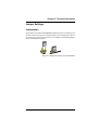
Ergonomic Notice
Now that you have your Micron computer, you will probably spend many
hours exploring the capabilities of this machine, and personalizing it for your
use. But the computer is only part of the larger picture of ergonomics.
Ergonomics is a science that addresses human performance and well-being in
relation to various types of jobs, tools, equipment and environment.
As you begin to personalize your working environment, it is important to
keep in mind your body’s needs to make your computer time more productive
with less physical and mental stress. And an effective work area will begin
from the ground up. Here are some suggestions:
•
Use an adjustable chair, and try different seated postures to find
what is most comfortable and produces the least fatigue. The
backrest should be adjustable to fit the small of your back.
•
Use an adjustable keyboard support. You want to keep your
wrists straight, your hands lower than your forearms and your
forearms parallel to the floor. Use a light touch on the keyboard.
•
Alternate mouse and keyboard use, and keep the mouse within
easy reach.
•
Place the monitor 18-30 inches from your eyes (arm’s length is
also a good distance). The top of the monitor should be level
with your eyes.
•
Take breaks from both the keyboard and looking at the monitor.
Performing simple exercises while at your work area will increase
your productivity. Shrug your shoulders...take a deep
breath...change your focus...massage your hands...stretch....let
your arms fall relaxed at your sides.
No two work areas will ever be the same. Find the combinations that work for
you, and keep in mind that proper work area planning will make your
computer time more effective, and less stressful on your body.
v
FCC Information
Class B Digital Device: This device complies with Part 15 of the FCC rules.
These limits are designed to provide reasonable protection against harmful
interference when the equipment is operated in a residential installation. This
equipment generates, uses, and can radiate radio frequency energy and, if not
installed and used in accordance with the instruction manual, may cause
harmful interference to radio communications. However, there is no guarantee
that interference will not occur in a particular installation. If this equipment
does cause harmful interference to radio or television reception, which can be
determined by turning the equipment off and on, the user is encouraged to try
to correct the interference by one of the following measures:
Reorient or relocate the receiving antenna.
Increase the separation between the equipment and receiver.
Connect the equipment into an outlet on a circuit different from that
to which the receiver is connected.
Consult an experienced radio/TV technician for help.
Note: Shielded interface cables must be used in order to comply with the
emission limits.
Caution: Changes or modifications not expressly approved by the party
responsible for compliance could void the user's authorization to operate the
equipment.
vi
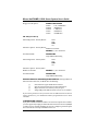
COMPLIANCE INFORMATION STATEMENT
DECLARATION OF CONFORMITY
Responsible Party:
Micron Electronics, Inc.
Address:
900 E. Karcher Road
Nampa, Idaho 83687
USA
Telephone:
FAX:
(208) 463-3434
(208) 463-3424
Type of Equipment:
ATX Tower Server
Model Name:
R440LX
This device complies with Part 15 of the FCC Rules. Operation is subject to the
following conditions:
1)
this device may not cause harmful interference, and
2)
this device must accept any interference received including
interference that may cause undesired operation.
vii
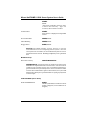
DECLARATION OF CONFORMITY
APPLICATION OF COUNCIL DIRECTIVE(S) 89/336/EEC and 72/23/EEC
Standard(s) to which Conformity is Declared:
EN55022
EN50082-1
EN60950
Manufacturer's Name:
Micron Electronics, Inc.
Manufacturer's Address:
900 E. Karcher Road
Nampa, Idaho 83687
USA
Micron Electronics, Inc., hereby declares Micron systems bearing the
marking are in compliance with the EMC (Electromagnetic Compatibility)
directive of the European Community and conform to the Directive(s) and
Standard(s) listed above.
A "Declaration of Conformity" for each system can be found on file at any
authorized European Micron Dealer/Distributor. For a list of authorized
dealers/distributors, please contact Micron Electronics, Inc. at 208-893-8970.
When requesting a "Declaration of Conformity," please refer to the FCC ID
number on the system label.
viii
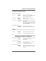
Table of Contents
Chapter 1
Setting Up Your System
Unpacking ........................................................................................................... 1-2
Setup .................................................................................................................. 1-3
Maintenance ....................................................................................................... 1-8
Removing the System Cover ........................................................................... 1-10
Chapter 2
Technical Information
Overview ............................................................................................................. 2-2
System Board ..................................................................................................... 2-3
Jumper Settings ................................................................................................. 2-5
Installing Add-on Peripherals ........................................................................... 2-12
Memory ............................................................................................................. 2-14
DIMM Modules ................................................................................................. 2-15
Chapter 3
Configuring the System
Setup .................................................................................................................. 3-2
Using System Configuration Utility .................................................................... 3-4
Configuration Settings for the System Board .................................................. 3-12
Server Management ......................................................................................... 3-19
Using Setup ...................................................................................................... 3-20
Setup Menus .................................................................................................... 3-22
Using SCSI Select ............................................................................................ 3-38
Installing Video Drivers .................................................................................... 3-47
Configuring Network Controller ........................................................................ 3-47
Chapter 4
Common Problems
Introduction ......................................................................................................... 4-2
Appendix A:
Appendix B:
Appendix C:
Appendix D:
Contacting Technical Support
Beep Codes and Error Messages
Glossary
Micron PowerSM Warranty
ix
Chapter 1: Setting Up Your System
Chapter 1
Setting Up Your System
Unpacking .................................................................................... 1-2
Check the Packaging ......................................................................................... 1-2
Unpack Your System ......................................................................................... 1-2
Check Your Packing List .................................................................................... 1-2
Setup ............................................................................................ 1-3
Getting Started ................................................................................................... 1-3
What You Need .................................................................................................. 1-3
Putting It All Together ......................................................................................... 1-3
Tower Case ........................................................................................................ 1-5
Running Your System for the First Time ........................................................... 1-7
Turning Off Your System ................................................................................... 1-7
Maintenance ................................................................................. 1-8
Operating Environment ...................................................................................... 1-8
Transporting ....................................................................................................... 1-8
Cleaning ............................................................................................................. 1-8
Protecting ........................................................................................................... 1-9
Backing Up ......................................................................................................... 1-9
Removing the System Cover .................................................... 1-10
Micron Electronics, Inc.
1-1
Micron NetFRAME LV2000 Server System User’s Guide
Unpacking
Check the Packaging
As soon as the packages containing your new system arrive, carefully inspect
them for any signs of damage. In particular, look for wrinkled or bent corners,
holes, or other signs of bad handling or abuse. If you notice any damage to the
packaging, immediately open the boxes and inspect the contents for damage.
Pay close attention to the components near the area where the packing material
was damaged.
Unpack Your System
Caution: If your system arrives in cold weather, do not unpack the computer
or the monitor until they have been allowed to come to room temperature.
Immediately exposing them to the warm room may cause condensation to
occur, which may damage the units. If condensation does occur, allow the
units to completely dry before operating them.
Follow these steps after you have determined that the packaging is undamaged:
1.
Taking care not to damage the packing material, carefully open
the cardboard box containing the computer and remove the
system unit, keyboard and any other accessories that you may
have ordered.
2.
Carefully unpack the monitor and all accessories from the
monitor package. Be careful not to damage the packing material.
3.
Inspect all items for damage that may have occurred during
shipment.
For your protection, report any damage to the shipper
immediately.
We highly recommend that you save the packaging in the event that you need
to move or ship the system some time in the future.
Check Your Packing List
Now that you have everything out of the packages, take the time to check the
packing list to be sure you received everything. If you discover that an item is
missing, call Micron Electronics, Inc. immediately to receive a replacement.
Refer to Appendix A for contact information.
1-2
Micron Electronics, Inc.
Chapter 1: Setting Up Your System
Setup
Getting Started
Before your new system left the factory, Micron configured the hardware. The
display adapter was set to work with your monitor and the hard disk was
partitioned and formatted with DOS using the standard default settings for
your machine. Your computer system is ready to go. All you have to do is
plug it in.
What You Need
❏
❏
❏
A grounded power outlet
Phillips-head screwdriver
Power filter/suppressor protector (recommended)
Putting It All Together
To complete your setup, refer to the following steps:
1.
Take a moment and review the case figures on the following
pages to acquaint yourself with the front and back of your system.
2.
Check the voltage selector on the rear of the unit. Be sure it is
switched for the proper voltage (115V in the United States and
Canada).
3.
Place the monitor where you wish, as long as its cable can still
reach the video connector at the rear of the computer.
4.
Unpack the power cable for the computer and plug the
appropriate end into the power inlet at the back of the system.
Insert the other end into a grounded power outlet. We highly
recommend that you obtain a protection device such as an
uninterruptable power supply (UPS), power filter or surge
suppressor. In this way you will be providing the utmost
protection for your system and data.
5.
Ensure that the system is turned OFF before proceeding.
Attaching peripherals while the power is on may damage the
unit or the peripheral.
6.
Locate the monitor’s power cable and plug the appropriate end
into the monitor (if not already attached). Insert the other end
into the grounded outlet or protection device.
Micron Electronics, Inc.
1-3
Micron NetFRAME LV2000 Server System User’s Guide
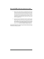
7.
Find the video cable and attach the appropriate end into the
monitor (if not already attached) and attach the other end into
the video connector (located in one of the expansion slots at the
rear of the unit). If the connection is loose on either end, tighten
the integrated screws at both ends of the cable for a secure
connection. For more information about the setup, use, and
maintenance of your video monitor, please refer to the manual
that was supplied with it.
8.
Insert the ends of the keyboard and mouse cables into the
keyboard and mouse connectors at the rear of the computer
system. Take care, for the connectors are keyed in such a way
that the plugs can only be inserted if oriented correctly. Refer to
the case drawings on the following pages for the location of the
proper connector. If it does not plug in easily, do not force it.
Your system should now be ready to use. You may have other devices or
peripherals to install, but it is best to ensure the basic system is operating
correctly before adding any options.
1-4
Micron Electronics, Inc.
Chapter 1: Setting Up Your System
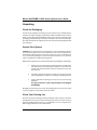
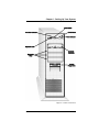
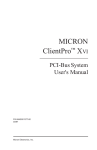
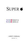
Figure 1-5. Tower Case-Front
Micron Electronics, Inc.
1-5
Micron NetFRAME LV2000 Server System User’s Guide
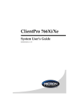
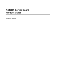
Figure 1-6. Tower Case-Rear
1-6
Micron Electronics, Inc.
Chapter 1: Setting Up Your System
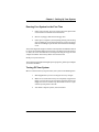
Running Your System for the First Time
1.
Power up the monitor. If you are unsure about this, please refer
to the monitor’s manual for more information.
2.
Remove any floppy disks from the floppy drive.
3.
Power up the computer system by firmly pushing and releasing
the On/Off button on the front panel of the system. The power
indicator should light up and the fan and hard drive should begin
to run.
The system diagnostics begins at this time. The keyboard is initialized indicated
by the keyboard LEDs blinking momentarily. The Num Lock LED remains
on. Next, the screen initializes and a message indicating what type of video
adapter is installed. The memory will be counted and tested.
Finally, the system is booted.
If you experience any problems during the power up sequence, please refer to Chapter
4, "Common Problems."
Turning Off Your System
Micron recommends that you power down your system in the following order:
1.
Exit all applications you are running and save any changes.
2.
Make sure that ALL disk activity has completely stopped. The
floppy and hard drive indicator lights should be off and the
floppy drive motors should stop. Hard disks continue to spin
until the system power is shut off.
3.
Turn off the computer system, then the monitor.
Micron Electronics, Inc.
1-7
Micron NetFRAME LV2000 Server System User’s Guide
Maintenance
Operating Environment
Your Micron computer has been manufactured to the highest standards. With
proper care, it should provide years of trouble-free service.
To ensure that your system has the longest life possible, it should be placed in
an area with good ventilation and low humidity, out of direct sunlight and
away from heat sources or lamps. Be sure the rear cooling-fan opening is not
obstructed as it is necessary to keep the system cool. Never expose the system
to any moisture. This could lead to fire or shock hazard. Stay away from areas
with high levels of dust, dirt, or smoke.
Transporting
Always shut the system off before moving it. Any sudden jar or shock may
permanently damage the hard drive. Hard drives are more resistant to shock
if they are shut down.
If you are transporting the system over a distance, it is a good idea to completely
repackage it in its original packing material. If the original packaging is
unavailable, pack all components with as much padding as reasonably possible
to ensure that the units are not exposed to excessive vibration or shock.
Cleaning
If the case becomes dirty through constant use or handling, use only a damp,
dust-free cloth for cleaning. Do not use abrasives or solvents as these may mar
or scratch the case. Window cleaner and a cloth can be used to clean the monitor,
if the monitor has been turned OFF first. Never apply the window cleaner
directly to the monitor screen. Always spray the cloth first, then wipe down
the screen.
Cleaning kits designed to clean floppy drives are available from most computer
stores and should be used periodically.
If you are operating your system in an environment heavy with smoke or
dust, you should occasionally open the unit and with great care, clean the
components with a vacuum (special vacuums are available just for this
purpose). Be careful to not loosen any of the components.
If liquid is spilled into the keyboard, immediately unplug it, allow the fluid to
drain out by tipping the keyboard upside down, and dry the keyboard
overnight before using it again.
1-8
Micron Electronics, Inc.
Chapter 1: Setting Up Your System
Protecting
To prevent normal electrical problems such as spikes or surges, install a power
surge/filter between the power outlet and all of the connected components. If
even one component is not connected, the entire system could be at risk.
If a severe storm enters your area, completely unplug the entire system from
all electrical sources, including phone lines. Lightning can travel in on any
line and destroy all connected components.
If possible, do not turn the system on and off frequently. This stresses the
power supply and may shorten the life of some components. To restart the
system, press the reset button located in the front of the case. If applications
are open and the system is reset or if the hard drive is active, data loss will
most certainly occur. If you do not use the reset button to restart the system, be
sure the hard drive has come to a complete stop before turning the computer
on again.
Backing Up
Even with today’s technology, data loss can occur at any time. We highly
recommend that you back-up often. There are a large number of backup systems
available from retail and mail-order outlets, including floppy drive backup
systems, tape backup systems, and optical backup systems. Any of these
alternatives are highly recommended. Complete, frequent backups can save
years of data from total and irretrievable destruction. If you require additional
information about backup systems or options, please contact Micron
Electronics, Inc.
Micron Electronics, Inc.
1-9
Micron NetFRAME LV2000 Server System User’s Guide
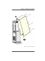
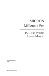
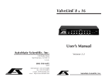
Removing the System Cover
Refer to the Figure on page 1-13. Use a #2 Phillips-head screwdriver or a 1/4"
hex driver.
1.
It is not necessary to disconnect the cable connectors on the back
of the computer before opening the cover. However, note where
the cables connect to the back for future reference . (If you have
a video camera, a quick scan of the rear case is helpful).
2.
Remove the screws from the back of the case cover. Keep these
screws together (they are a different size than the other screws
in your system) for they are not to be interchanged.
3.
With flat palms placed on each side of the cover, pull the cover
back until the cover's front top lip clears the chassis channel
(about 3/4"). Grasp the top-rear of the cover and lift up in one
smooth motion until the cover clears the chassis.
To replace the cover, gently lower the top lip of the cover into the chassis
channel at an angle before lowering the rear into place. With the lip inserted
in the channel, push the rear of the cover forward to seat it flush and replace
the screws. Note the metal rail guides located inside the bottom of the cover
which must fit over the bottom metal case frame when the cover is replaced.
1-10
Micron Electronics, Inc.
Chapter 1: Setting Up Your System
Figure 1-7. System Cover Removal
Micron Electronics, Inc.
1-11
Chapter 2: Technical Information
Chapter 2
Technical Information
Overview ...................................................................................... 2-2
System Features ................................................................................. 2-2
System Board .............................................................................. 2-3
Jumper Settings .......................................................................... 2-5
Configuration ...................................................................................... 2-5
General Porcedure to Change Jumper Setting .................................. 2-6
Function Pins ...................................................................................... 2-7
CMOS Jumper .................................................................................... 2-8
Password Jumper ............................................................................... 2-8
Recovery Boot Jumper ....................................................................... 2-8
Boot Block Write Jumper .................................................................... 2-9
CPU Speed Jumper .......................................................................... 2-10
FRB Timer Enable Jumper ............................................................... 2-10
Chassis Intrusion Detection Jumper ................................................. 2-11
Host Bus In-order Queue Jumper ..................................................... 2-11
Installing Add-On Peripherals .................................................. 2-12
PCI Local Bus Card .......................................................................... 2-12
Add-In Board Slots ............................................................................ 2-13
Memory....................................................................................... 2-14
DIMM Sizes and Compatibility .......................................................... 2-14
DIMM Modules ........................................................................... 2-15
Installing DIMM Modules .................................................................. 2-15
Removing DIMM Modules ................................................................ 2-17
Micron Electronics, Inc.
2-1
Micron NetFRAME LV2000 Server System User’s Guide
Overview
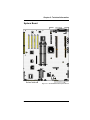
Micron's NetFRAME LV2000 features a high-performance system board
designed to be the basis for your server system. The NetFRAME LV2000 is
based on Intel’s 440LX chipset and the Pentium II processor..
System Features
2-2
❏
ATX form factor.
❏
Supports up to two Pentium II processors.
❏
Four 72-bit sockets for SDRAM dual inline memory modules
(DIMM), 32 to 512 MB.
❏
512 KB of flash ROM.
❏
One ISA and four PCI expansion slots.
❏
Integrated onboard Cirrus Logic CL-GD5446 super video
graphics array (SVGA) controller; 1 MB video memory.
❏
Adaptec AIC-7880 Wide, Fast-20, PCI 2.1-compliant SCSI
controller.
❏
Integrated onboard NIC. Intel 82557 PCI LAN controller
for 10 or 100 Mbps TX Fast Ethernet networks. RJ45 Ethernet
connector and indicator LEDs at I/O back panel.
Micron Electronics, Inc.
Chapter 2: Technical Information
System Board
Figure 2-1. NetFRAME LV2000 System Board
Micron Electronics, Inc.
2-3
Micron NetFRAME LV2000 Server System User’s Guide
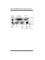
Figure 2-2. Back Panel Connector Layout
2-4
Micron Electronics, Inc.
Chapter 2: Technical Information
Jumper Settings
Configuration
The jumpers on the Micron NetFRAME LV2000 are preset at the factory and
in most cases do not need to be changed. However, if certain functions need to
be changed, the jumpers may need to be reconfigured. The following figure
shows an example of a jumper.
Figure 2-3. Example of a Jumper and Jumper Block
Micron Electronics, Inc.
2-5
Micron NetFRAME LV2000 Server System User’s Guide
Figure 2-4. Jumpers J3J1 and J2J1
General Procedure to Change Jumper Setting
The short general procedure described here for changing a configuration setting
is the same for most of the jumper functions.
1. Observe the safety precautions at the beginning of this manual.
2. Turn off all connected peripherals, turn off system power, and
disconnect the AC power cord.
3. Remove the cover. You do not need to remove the system board
from the chassis, and you probably do not need to remove any
add-in boards.
4. Locate the configuration jumpers at the edge of the system board
toward the front of the system.
5. Move jumper to pins specified for the desired setting.
6. Reinstall the cover, connect the power cord, and turn on the
system for the change to take effect.
You may need to repeat these steps to move the jumper back to its original
setting, depending on the jumper function.
2-6
Micron Electronics, Inc.
Chapter 2: Technical Information
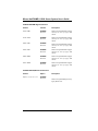
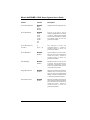
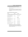
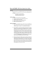
Function Pins (default in bold)
What it does at system reset:
CMOS clear
1-2, Protect
2-3, Erase
Preserves the contents of NVRAM.
Replaces the contents of NVRAM with the
manufacturing default settings.
Password clear
5-6, Protect
6-7, Erase
Maintains the current system password
Clears the password.
Recovery Boot
9-10, Normal
System attempts to boot using the BIOS stored
in flash memory.
BIOS attempts a recovery boot, loading BIOS
code from a floppy diskette into the flash
device. This is typically used when the BIOS
code has been corrupted.
10-11, Recovery
Boot Block Write Protect
13-14, Protect
14-15, Program
BIOS boot block is write-protected.
BIOS boot block is erasable and programmable.
CAUTION
Programming the boot block incorrectly will prevent the system from booting.
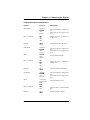
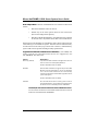
CPU Speed
1-2, Protect
Processor speed configuration is protected.
2-3, Enable
Processor speed configuration is enabled.
Note
Depending on your configuration, this jumper is either available
to set the speed of the processor, or not available at all.
FRB Timer Enable 5-6, Enable
6-7, Disable
Chassis Intrusion Detection
9-10, Enable
10-11, Disable
Host Bus In-order Queue
13-14, Max
14-15, Min (1)
Micron Electronics, Inc.
FRB operation is enabled (system boots from
processor 1 if processor 0 fails).
FRB is disabled.
Switch installed on chassis indicates when
cover has been removed.
Chassis intrusion switch is bypassed.
Host in-order queue depth is set at maximum.
Host in-order queue depth is set at 1 (used for
debugging).
2-7
Micron NetFRAME LV2000 Server System User’s Guide
CMOS Jumper
The jumper at pins 1, 2, and 3 controls whether settings stored in CMOS
nonvolatile memory (NVRAM) are retained during a system reset.
Procedure to restore the system’s CMOS and RTC to default values:
1.
2.
See “General Procedure to Change Jumper Setting” on page 2-6.
Move the CMOS jumper from pins 1 and 2 to pins 2 and 3 (the Clear
CMOS memory position).
3.
Reinstall the side cover for your safety, and connect the power cord to
the system.
4. Turn the system on. Wait for POST to complete and for the messages
“NVRAM cleared by jumper” and “Press F2 to enter Setup” to appear.
This automatically reprograms CMOS and RTC to their default settings.
5.
Enter Setup and make any changes necessary (for example, changing
the boot device). Press F10 to save the new Setup configuration and exit
Setup.
6.
Turn off the system, and disconnect the power cord from the system.
7.
Again remove the side cover.
8.
Move the jumper from pins 2 and 3 back to pins 1 and 2 (the Protect
CMOS memory position).
9.
Reinstall the side cover, and connect the power cord to the system.
10. Run BIOS Setup or the SCU to verify the correct settings. See Chapter 3.
Password Jumper
The jumper at pins 5, 6, and 7 controls whether a stored password is retained
or cleared during a system reset.
Procedure to clear the current password and then enter a new one:
1.
2.
3.
4.
5.
6.
7.
8.
9.
See “General Procedure to Change Jumper Setting” on page 2-6.
Move the Password jumper from pins 5 and 6 to pins 6 and 7.
Reinstall the side cover for your safety, and connect the power cord to
the system.
Turn the system on, and wait for POST to complete. This automatically
clears the password.
Turn off the system, and disconnect the power cord.
Again remove the side cover.
Move the jumper from pins 6 and 7 back to pins 5 and 6.
Reinstall the side cover, and connect the power cord to the system.
Run the SCU to specify a new password. See Chapter 3.
Recovery Boot Jumper
The jumper at pins 9, 10, and 11 controls whether the system attempts to boot
using the BIOS programmed in Flash memory.
Procedure to disable recovery booting:
1.
2.
2-8
See “General Procedure to Change Jumper Setting” on page 2-6.
Move the recovery boot jumper from pins 9 and 10 to pins 10 and 11.
Micron Electronics, Inc.
Chapter 2: Technical Information
3.
4.
Reinstall the side cover for your safety, connect the power cord to the
system.
Turn the system on, and insert the Flash Memory Update Utility diskette
in drive A. After the system boots, the speaker emits a single beep and
the recovery process starts. This takes about three minutes. When the
recovery process completes, the speaker emits two beeps.
While in the recovery mode, there is no screen display on the monitor.
The keyboard is disabled as the system automatically recovers the
BIOS. The following beep codes describe the recovery status.
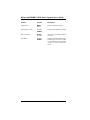
Beep Code
2
4
Continuous beeps
5.
6.
7.
8.
Message
Successful completion, no errors.
The system could not boot from the diskette. The
diskette may not be bootable.
The wrong BIOS recovery files are being used and/or
the flash memory jumper is in the wrong position.
Turn the system off, disconnect the power cord(s) from the system, and
remove the left side cover.
Move the jumper from pins 9 and 10 to pins 10 and 11 to enable the
normal boot mode.
Replace the left side cover, remove the diskette from drive A, and connect
the power cord(s) to the system.
After running the special recovery mode, run the SCU to specify a new
password. See Chapter 3.
Boot Block Write Protect Jumper
The jumper at pins 13, 14, and 15 controls whether the BIOS boot block is
protected from being erased and reprogrammed.
CAUTION, leave boot block jumper at factory-default setting
Programming the boot block incorrectly will prevent the system from booting.
Programming should only be done by a technically qualified person. The
procedure requires a special “Boot Block Update Utility.” Contact your dealer
or sales representative for more information.
Procedure to permit boot block erasing and programming:
1. See “General Procedure to Change Jumper Setting” on page 2-6.
2.
3.
4.
5.
6.
7.
8.
Move the boot block jumper from pins 13 and 14 to pins 14 and 15 to
erase and program the BIOS boot block.
Reinstall the side cover for your safety, and connect the power cord to
the system.
Run the Boot Block Update Utility.
Turn off the system, and disconnect the power cord from the system.
Remove the side cover.
Move the jumper from pins 14 and 15 back to pins 13 and 14 to write
protect the BIOS boot block.
Reinstall the side cover, and connect the power cord to the system.
Micron Electronics, Inc.
2-9
Micron NetFRAME LV2000 Server System User’s Guide
CPU Speed Jumper
The jumper at pins 1, 2, and 3 controls whether you can configure the speed of
the processor.
Note
Depending on your configuration, this jumper is either available to set the
speed of the processor, or not available at all. If available, enabling this jumper
will activate the CPU Speed Setting field in the Main Menu of the BIOS Setup
Utility. See Chapter 3.
Procedure to enable processor speed configuration:
1.
2.
3.
4.
5.
6.
7.
8.
See “General Procedure to Change Jumper Setting” on page 2-6.
Move the processor speed jumper from pins 1 and 2 to pins 2 and 3.
This activates the CPU Speed Setting field in the BIOS Setup Utility.
Reinstall the side cover for your safety, and connect the power cord to
the system.
Run the BIOS Setup Utility as described in Chapter 3.
Select the proper speed for your processor.
Again remove the side cover.
Move the processor speed jumper from pins 2-3 back to pins 1-2.
Reinstall the side cover for your safety, and connect the power cord to
the system.
FRB Timer Enable Jumper
The jumper at pins 5, 6, and 7 controls whether the system boots from processor
1 if processor 0 fails.
Procedure to disable FRB timer:
1.
2.
3.
4.
5.
2-10
See “General Procedure to Change Jumper Setting” on page 2-6.
Move the recovery boot jumper from pins 5 and 6 to pins 6 and 7.
Reinstall the side cover for your safety, and connect the power cord to
the system.
Turn the system on, and wait for POST to comlpete.
Run the SCU to configure the system. See Chapter 3.
Micron Electronics, Inc.
Chapter 2: Technical Information
Chassis Intrusion Detection Jumper
The chassis contains an alarm switch that sends a notification signal to the
server management software if a cover is removed. The jumper at pins 9, 10,
and 11 controls whether this alarm feature is enabled or disabled.
Procedure to disable (bypass) the chassis intrusion switch:
1.
2.
3.
4.
5.
See “General Procedure to Change Jumper Setting” on page 2-6.
Move the chassis intrusion detection jumper from pins 9 and 10 to pins 10
and 11 to disable the alarm switch.
Reinstall the side cover for your safety, and connect the power cord to
the system.
Turn the system on, and wait for POST to complete.
Run the SCU to configure the system. See Chapter 3.
To enable the intrusion switch, do the above steps but move the jumper back
to pins 9 and 10.
Host Bus In-order Queue Jumper
The jumper at pins 13, 14, and 15 controls whether the host bus in-order queue
is set at maximum or minimum (one).
Procedure to change setting of the host bus in-order queue from maximum to
minimum (one):
1.
2.
3.
4.
5.
See “General Procedure to Change Jumper Setting” on page 2-6.
Move the chassis intrusion detection jumper from pins 13 and 14 to pins
14 and 15 to disable the alarm switch.
Reinstall the side cover for your safety, and connect the power cord to
the system.
Turn the system on, and wait for POST to complete.
Run the SCU to configure the system. See Chapter 3.
To change the setting to maximum, do the above steps but move the jumper
back to pins 13 and 14.
Micron Electronics, Inc.
2-11
Micron NetFRAME LV2000 Server System User’s Guide
Installing Add-On Peripherals
The NetFRAME LV2000 accommodates ISA and PCI Local Bus cards. Extra
SDRAM can also be added to the system board. The following describes how
to install the PCI card and SDRAM memory.
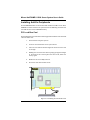
PCI Local Bus Card
PCI Local Bus slots accommodate most PCI-approved Local Bus cards. To install
a PCI Local Bus card:
1.
Power OFF the computer system.
2.
Locate an unused PCI slot on the system board.
3.
Insert the card with the bottom edge level. Never insert the card
at an angle.
4.
Holding the card at the center of the top edge, gently push straight
in. Do not force the card into place. If it does not fit, take it out
and try again.
5.
Make sure the card is fully inserted.
6.
Secure the card with a bracket screw.
Figure 2-5. Installing a PCI Local Bus Card
2-12
Micron Electronics, Inc.
Chapter 2: Technical Information
Add-in Board Slots
The system board has one full-length dedicated ISA bus slot, which can have
a bus master in it. ISA features:
❏
❏
❏
❏
❏
❏
Bus speed up to 8.33 MHz
16-bit memory addressing
Type A transfers at 5.33 Mbps
Type B transfers at 8 Mbps
8- or 16-bit data transfers
Plug and Play ready
The system board also has four dedicated full-length PCI slots. PCI features:
❏
❏
❏
❏
❏
❏
❏
Bus speed up to 33 MHz
32-bit memory addressing
5 V signaling environment
Burst transfers of up to 133 Mbps
8-, 16-, or 32-bit data transfers
Plug and Play ready
Parity enabled
Micron Electronics, Inc.
2-13
Micron NetFRAME LV2000 Server System User’s Guide
Memory
Only SDRAM is supported by the system board. Memory is partitioned as
four banks of SDRAM DIMMs, each providing 72 bits of noninterleaved
memory (64-bit main memory plus ECC):
❏
Install from 32 MB to 512MB of memory, using up to four doublebanked DIMMs.
❏
Install from 32 MB to 512 MB of memory, using up to four singlebanked DIMMs.
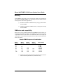
DIMM sizes and compatibility
We do not test every possible combination of DIMM sizes and vendors. To
avoid potential memory problems, use DIMMs that have been tested for
compatibility with the system board. The table below lists some sample size
combinations. Contact your sales representative or dealer for more information
about your system.
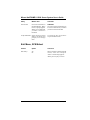
Sample DIMM Component Combinations
Bank 0
(slot J1)
Bank 1
(slot J2)
32
32
32
32
32
128
32
32
32
128
128
❏
2-14
Bank 2
(slot J3)
128
128
128
128
Bank 3
(slot J4)
128
128
128
Total memory
32 MB
64 MB
192 MB
320 MB
416 MB
512 MB
Questions and purchases for memory expansion may be directed
to Micron Memory Module sales (1-800-438-3343).
Micron Electronics, Inc.
Chapter 2: Technical Information
DIMM Modules
The memory in this system can be increased up to a maximum of 512MB by
installing DIMMs (dual in-line memory modules). To install DIMMs, first locate
the memory banks on the system board (refer to Figure 2-1). Follow the table
on page 2-14 for the possible installation combinations.
CAUTION: Modules are Electrostatic Sensitive.
Even a small electrostatic discharge could damage the module. A damaged
module might not fail immediately, but over time it will become worse,
possibly causing an "intermittent" problem. Be very careful to handle the
boards ONLY by the edges. DO NOT touch the gold/silver edge-connectors
or any of the components on the board. Leave the module in the antistatic
bag until ready for installation.
1.
Switch the computer off. Leave the computer plugged in to the
outlet to provide an electrical ground to discharge static
electricity.
2.
Touch the metal case of the power supply or the metal lining
inside the computer case. This will drain the static charge from
your body and will keep the modules from being electrically
damaged.
3.
Keep body movement to a minimum as you remove and handle
the modules. Antistatic wrist straps with clip-on ends are
commercially available.
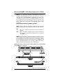
Installing DIMM Modules
The NetFRAME LV2000 has four, 72-pin DIMM sockets on-board and can
accommodate ECC or non-ECC SDRAM memory from 32MB up to 512MB
using the DIMM combinations on page 2-14.
There are no jumper settings required for the memory size or type, which is
automatically detected by the system BIOS. Gold leaded DIMMs are required
to be used when adding system memory.
Micron Electronics, Inc.
2-15
Micron NetFRAME LV2000 Server System User’s Guide
Step 1: Using both hands, carefully set the DIMM into the center of
the left and right latching levers. Center the module over the socket
so that the notches are aligned with the socket keys. Do not force it in
or damage may result. Note that the DIMM modules are keyed in
such a way that they cannot be inserted incorrectly (refer to the
figure below). If you are having difficulty placing them into the
socket, check to see that you are not attempting to insert them
backwards.
Do not lock the module into position at this time.
Step 2: Check to make sure the module is centered in the socket, and
that the connector pins of the module line up with the socket connector
pins.
A)
Be sure the module is centered and connector pins are
aligned.
B)
When the module is locked in place, be sure both latching
levers are fully seated into latching notches in the sides of
the DIMMs.
Step 3: Using both hands and applying equal pressure on each end
of the module, lock the module into the socket by pushing downward
with the thumbs and squeezing inward with the forefingers. Make
sure both latching levers have seated fully into the modules latching
notch. The module should now be standing upright in the socket.
Refer to the fully seated drawing on the following page.
WARNING: Failure to observe proper insertion guidelines may result in damage
to the DIMM and/or the socket.
Figure 2-6. Proper DIMM Insertion
2-16
Micron Electronics, Inc.
Chapter 2: Technical Information
Figure 2-7. DIMM Fully Seated
Removing DIMM Modules
To remove DIMM modules, simply reverse the installation procedure with
the following differences. Using the thumbs of both hands, gently pry the
latching levers open so they no longer hold the module in the socket. Gently
lift the module upward to clear the latching levers.
Micron Electronics, Inc.
2-17
Chapter 3: Configuring the System
Chapter 3
Configuring the System
Setup ............................................................................................ 3-2
BIOS Setup ........................................................................................................ 3-2
When Setup Should be Run ............................................................................... 3-2
Power On Self Test ............................................................................................ 3-3
Using System Configuration Utility (SCU) ................................. 3-4
Where the SCU Gets Information ...................................................................... 3-4
When to Run the SCU ........................................................................................ 3-5
Record your SCU Settings ................................................................................. 3-5
How to Enter and Start the SCU ........................................................................ 3-5
Six Steps in Using the SCU ........................................................ 3-7
SCU Utilities ..................................................................................................... 3-11
Configuration Settings for the System Board ......................... 3-12
Server Management .................................................................. 3-19
Using Setup ............................................................................... 3-20
If You Cannot Access Setup ............................................................................ 3-21
How to Enter and Start Setup .......................................................................... 3-21
Setup Menus .............................................................................. 3-22
Main Menu ........................................................................................................ 3-23
AdvancedMenu ............................................................................................... 3-26
Security Menu .................................................................................................. 3-31
Server Menu ..................................................................................................... 3-33
Boot Menu ........................................................................................................ 3-35
Exit Menu .......................................................................................................... 3-37
Using SCSI Select ...................................................................... 3-38
How to enter and Start SCSI Select ................................................................ 3-38
Main Menu ........................................................................................................ 3-39
Exit Menu .......................................................................................................... 3-46
Installing Video Drivers ............................................................. 3-47
Configuring Network Controller ............................................... 3-47
Micron Electronics, Inc.
3-1
Micron NetFRAME LV2000 Server System User’s Guide
SETUP
BIOS Setup
Every AT-compatible computer has a battery supported CMOS memory
location that stores information about the system and peripheral configuration.
Because of the attached battery, the CMOS is constantly provided with power,
even when the computer has been turned off.
During the boot sequence, a special software application called the BIOS (Basic
Input Output System), located in read-only (ROM) memory on the system
board, reads the information contained in the CMOS and configures the CPU
and other peripheral devices. If the CMOS information is incorrect, the system
may not operate correctly until accurate information is stored in the CMOS.
The Setup Program has been built into the system to provide the means for
changing the CMOS.
When Setup Should Be Run
Although the Micron NetFRAME LV2000 arrives fully configured, the system
may need to be adjusted to fit your needs.
Whenever peripherals are added or removed from the system (for example, if
you add a hard disk or more memory), you must run Setup to inform the
system about the new configuration.
If the information in CMOS is lost, the system will not operate properly unless
Setup is used to restore the system configuration.
3-2
Micron Electronics, Inc.
Chapter 3: Configuring the System
Power-on Self Test (POST)
Each time you turn on the system, POST starts running. POST checks the
system board, processor, memory, keyboard, and most installed peripheral
devices. During the memory test, POST displays the amount of memory that
it is able to access and test. The length of time needed to test memory depends
on the amount of memory installed. POST is stored in flash memory.
1.
Turn on your video monitor and system. After a few seconds
POST begins to run.
2.
After the memory test, these screen prompts and messages
appear:
Press <F2> key if you want to run SETUP
Keyboard.....Detected
Mouse........Detected
3.
If you do not press <F2> and do NOT have a device with an
operating system loaded, the above message remains for a few
seconds while the boot process continues, and the system beeps
once. Then this message appears:
Insert bootable media in the appropriate drive
If you do not press <F2> and DO have an operating system
loaded, the boot process continues, and this message appears:
Press <Ctrl><A> for SCSISelect(TM) Utility!
4.
Press <Ctrl+A> if there are SCSI devices installed. When the
utility opens, follow the displayed instructions to configure the
onboard Adaptec AIC-7880 Ultra-wide SCSI host adapter settings
and to run the SCSI utilities.
If you choose not to press <Ctrl><A> (SCSISelect Utility), the
boot process continues. After POST completes, the system beeps
once.
What appears on the screen after this depends on whether you have an
operating system loaded and if so, which one.
If the system halts before POST completes running, it emits a beep code
indicating a fatal system error that requires immediate attention. If POST can
display a message on the video display screen, it causes the speaker to beep
twice as the message appears.
Note the screen display and write down the beep code you hear; this
information is useful for your service representative. For a listing of beep
codes and error messages that POST can generate, see the “Solving Problems”
chapter in this manual.
Micron Electronics, Inc.
3-3
Micron NetFRAME LV2000 Server System User’s Guide
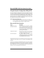
Using the System Configuration Utility (SCU)
The System Configuration Utility (SCU) is the main tool to configure the system
or to check or change the configuration. Many system settings can be entered
from either the SCU or Setup, but the SCU provides conflict resolution as well
as access to information about ISA, ISA Plug and Play, and PCI adapters. The
SCU is PCI-aware, and it complies with the ISA Plug and Play specifications.
The SCU works with any compliant configuration (.CFG) or overlay (.OVL)
files supplied by a peripheral device manufacturer.
System must have a diskette drive
The system must have a diskette drive present and enabled to use
the SCU. If a diskette drive is present but is disabled or misconfigured,
use the BIOS Setup utility to enable or configure the drive.
Where the SCU Gets Information
Source
Configuration (.CFG)
and overlay (.OVL) files
Configuration registers
User selected options
Description
For the system board, we provide a .CFG file
and an .OVL file with the SCU. These files
describe the board’s characteristics and the
system resources required. Some ISA adapters
come with a diskette that contains a .CFG file
(and an optional .OVL file).
Information and required resources for PCI
and Plug and Play adapters are derived from
the adapter’s configuration registers.
The SCU displays the exact system
configuration and the user’s current settings
by reading ISA CMOS and system nonvolatile
storage (NVRAM or flash memory).
Using information from the sources listed above, the SCU stores the system
configuration in ISA CMOS and system nonvolatile storage (NVRAM or flash
memory).
At power-on or rebooting, the BIOS POST routines and the Plug and Play
Auto Configuration Manager check and configure the hardware. If possible,
POST will program the hardware according to the configuration stored by the
SCU; if conflicts exist, an error message will be generated. You must then use
the SCU to correct the conflict before the system boots.
3-4
Micron Electronics, Inc.
Chapter 3: Configuring the System
When to Run the SCU
❏
❏
❏
❏
❏
When you first set up and configure the system
If you get a configuration error message at power-on
Whenever you add, remove, or move an ISA adapter that is not
Plug and Play
Whenever you add or remove memory
In general, whenever you add hardware to or remove hardware
from the system
Running the SCU is also recommended but optional for Plug and Play and
PCI adapters.
Record Your SCU Settings
Record your SCU settings. If the default values ever need to be restored (after
a CMOS-clear, for example), you must run the SCU to reconfigure your system.
Referring to the worksheets could make your task easier.
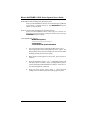
How to Enter and Start the SCU
Copy SCU to diskette
Before you can run the SCU from a diskette, you must copy the SCU
from the Configuration Software CD to a diskette.
1.
Turn on your video display monitor and system.
2.
You can enter and start the SCU in three different ways. Whether
or not you can use the second and third ways described in the
following table depends on how much main memory is used by
drivers loaded on the system.
Use diskette
Always start with a diskette that contains the SCU you copied from
the Configuration Software CD.
You can start the SCU from these sources:
How to do it:
From diskette at boot time.
Insert your SCU diskette in drive A. Press the reset button or type
<Ctrl+Alt+Del> to reboot the system.
Micron Electronics, Inc.
3-5
Micron NetFRAME LV2000 Server System User’s Guide
From diskette after installing your operating system.
Insert your SCU diskette in drive A. At the DOS prompt, type a: and
press <Enter> to change to drive A. Type AUTOEXEC and press
<Enter> to start the SCU.
From a hard drive after installing your operating system.
Insert your SCU diskette in drive A and copy the contents to a
directory on your hard drive. Change to that directory, and type
AUTOEXEC and press <Enter>.
A message like this appears:
MS DOS startup menu
———————————————1. Execute SCU
2. Execute SCU for system with PNP OS
3-6
3.
If your operating system is not Plug and Play aware, type 1.
If your operating system is Plug and Play aware, type 2. The
Plug and Play-aware OS then manages the resources of all PCI
and Plug and Play devices in the system.
4.
When the SCU title appears on the screen, press any key to
continue.
5.
From the main menu, press <- > or <¯> to highlight an item and
then press <Enter> to select it. If you are using a mouse, point to
an item and single-click the left button to select it. Press <F1> at
any time for help about a selection.
6.
From the main menu, select “Step 1: About System
Configuration” for information about setting up the system.
Micron Electronics, Inc.
Chapter 3: Configuring the System
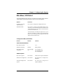
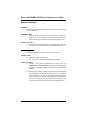
Six Steps in Using the SCU
The SCU main menu lists six steps to configure your system.
System Configuration Utility
Step 1:
About System Configuration
Step 2:
Add and Remove Boards
Step 3:
Change Configuration Settings
Step 4:
Save Configuration
Step 5:
View Switch/Jumper Settings
Step 6:
Exit
Step 1 displays a brief text overview of the SCU and some important terms
and definitions. Most experienced users will skip this step. The rest of the
steps will be described in the following pages.
Micron Electronics, Inc.
3-7
Micron NetFRAME LV2000 Server System User’s Guide
Add and Remove Boards
Use step 2 to add, delete, or move boards. Most ISA boards cannot be detected
automatically by the SCU, so you MUST use this step to add them to the system.
However, PCI and ISA Plug and Play boards ARE automatically detected and
added by the SCU. If the SCU did not detect a board, you can add a board
using this step.
To add a board:
1. Press <Ins>.
2. From the Select the Board to Add dialog box, select the board’s
.CFG file and press <Enter>.
To delete an existing board:
1. Use the arrow keys to select the board you want to delete.
2. Press <Del>.
3. Confirm that you want to delete the board.
To move a board from one slot to another:
1. Use the arrow keys to select the board you want to move.
2. Press <F7>.
If you add, move, or remove boards
Manually verify the resource settings of these adapters, and any other
adapters that are not locked, before saving your configuration.
To define an ISA board:
1.
Press <F6> to display the ISA Board Definition dialog box. Refer
to the section below for details.
Define an ISA Board
To define an ISA board that has no .CFG file, press <F6> while viewing the
Add and Remove Boards screen. The ISA Board Definition dialog box will
appear. It is necessary to define a board to prevent other boards in the system
from using the same IRQ levels, DMA channels, I/O addresses, or memory
addresses as that of the ISA board.
If there is an ISA board already installed, you can press <F9> to load its
definition and then modify that definition for a new ISA board you are
installing.
3-8
Micron Electronics, Inc.
Chapter 3: Configuring the System
If there is no ISA board installed, do the following steps:
1.
2.
3.
4.
5.
6.
7.
8.
9.
In the Board Name box, type a description of the board.
In the Manufacturer box, type the name of the board
manufacturer.
From the Board Type box, choose the type of board.
From the Board Slot box, choose the type of slot.
In the DMA box, define up to four DMA channels.
In the IRQ box, define up to seven IRQ levels.
In the Ports box, define up to eight ranges of I/O ports.
In the Memory box, define up to eight memory address ranges.
Press <F10> to save the ISA board definition.
To load an existing ISA board: Press <F9>.
To delete an ISA board: Press <F9>, and confirm that you intend to delete the
ISA definition.
Change Configuration Settings
Use step 3 to view or change the configuration settings for any board in the
system. You can verify that the system board and adapter board resources are
set properly. Configuring the system board involves a number of options.
To view or change the settings for a board:
1. Use the arrow keys to select the board.
2. Press <Enter>.
3. When you are satisfied with the current settings, press <Esc> to
return to the main menu.
Advanced Options
The Advanced Options menu is intended for advanced users. These options
are available:
Advanced Options
Global resource map
Select to view this information:
A list of allocated resources (DMA, logical slot, IRQ,
ports, and memory)
Board details
Details about individual boards
System details
Information on the add-in board slots: slot number,
type, whether bus master or not, NVRAM size
To view the Advanced Options menu: from the Change Configuration
Settings dialog box, press <F9>.
Micron Electronics, Inc.
3-9
Micron NetFRAME LV2000 Server System User’s Guide
Save Configuration
This step saves the configuration settings to nonvolatile RAM as well as to a
backup file (.CMS file). You must save your settings once they have been
configured.
View Switch/Jumper Settings
Use this step to view manufacturer’s instructions about setting dip switches
and jumpers on add-in boards and about running utilities to ensure the correct
configuration of each adapter.
This step does not provide switch and jumper information about the system
board.
Exit
This step exits to the operating system. If any configuration settings were
changed, you will be prompted to restart your system to see the changes.
3-10
Micron Electronics, Inc.
Chapter 3: Configuring the System
SCU Utilities
At the bottom of the main SCU menu, there is an option to press <F9> to
display the Utilities menu. The menu lists options that control how a
configuration is produced. For most of these choices, select the option line
and press the spacebar to enable/disable the option.
For descriptions of the options, press <F1> for help while the Utilities menu
displays on the screen. Here is a little more information about some of the
utilities:
Advanced/Dealer Mode—some ISA boards can be shipped with configuration
files that contain options that are not ordinarily configured by end users. If
this mode is turned on, any functions marked as EXP (expert) in the shipped
configuration file will be visible and can be updated.
Force new configuration—this option forces the SCU to ignore any information
stored in the Extended System Configuration Data (ESCD) structure in
NVRAM. This means that any ISA boards will “disappear” and that PCI and
Plug and Play ISA settings will be reset.
Specify name for .cms, .inf, and .set files—this option prompts you for the
base filename for the .CMS, .INF, and .SET files. This allows you to save
configuration information into different filenames. Otherwise, each time a
save operation completes in the SCU, the .CMS, .INF, and .SET files will be
overwritten. In this system, the default base filename is int31e0, so when the
SCU is saved, the files int31e0.cms, int31e0.inf, and int31e0.set are created.
Press <F5> to restore a configuration from a CMS file—a .CMS file is created
each time you do a save operation in the SCU. The file contains a copy of the
ESCD image as it was stored into nonvolatile memory and can be used to
restore this information at a later time. If the configuration information is
accidentally erased or a mistake has been made during the configuration
process, it might be desirable to restore to a previous configuration. The backup
.CMS file provides this mechanism to restore the ESCD image.
Press <F7> to define an ISA board. If you have an ISA board with no .CFG file,
you can use the ISA Board Definition screen to define the board. (You can
access the same menu from SCU Step 2 by pressing <F6>.)
Micron Electronics, Inc.
3-11
Micron NetFRAME LV2000 Server System User’s Guide
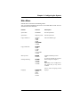
Configuration Settings for the System Board
When you select SCU step 3, Change Configuration Settings, there are many
menus and options available under that heading. This section about the SCU
shows the screen information that displaysafter you select the system board
from the Change Configuration Settings screen.
❏
❏
❏
Default values are in bold type.
Select an option and press <Enter> to display the menu for an
option.
Some items are displayed only, with no selection available here.
Some of the option choices are described below the grouping. Not all of them
are described because (A) a few are not user-selectable but are displayed for
your information, and (B) many of the option choices are relatively selfexplanatory.
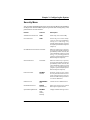
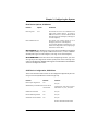
Systems Group
System Identification and Version Information
System Identification String
Displays System Identification String
Config and Overlay Version
Displays SCU configuration and overlay
version number
Displays
BIOS
version,
X.XXX.XXXX.X.XXXXXXXXXX
1.1/1.4
System Processor Displays Pentium II
Processor at {XXX} MHz
BIOS Version String
MP Spec Version
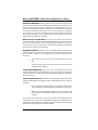
Memory Subsystem Group
Shadowing ISA ROMs Options
Extended Memory Options
(Cache, 1MB ISA Hole)
Press <Enter> to modify the shadowing
options
15 MB Extended Memory / 256 KB Cache
(WB)
Shadowing ISA ROMs Options—all onboard adapter ROM (stored
in compressed form in the system flash ROM) and PCI adapter ROM
will be shadowed into RAM in the ISA-compatible ROM adapter
memory space between C0000h to DFFFFh. Any BIOS found on ISA
devices that can be shadowed will be shadowed into adapter memory
space in the same range after initialization. ISA cards that require
memory-mapped read/write accessibility should be located into the
15M-16M ISA space, or the 512-640KB space, which may be enabled
individually via the SCU. Shadowing for ISA devices can be disabled
for various regions via the SCU. A PCI BIOS is always shadowed.
3-12
Micron Electronics, Inc.
Chapter 3: Configuring the System
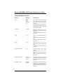
Onboard Disk Controllers
Onboard Floppy Controller
Primary Onboard IDE Controller
Enable Primary/Enable Secondary/
Disable
Enable/Disable
Onboard Communication Devices
Serial Port 1 Configuration
Port:3F8h IRQ:4
Port:2F8h IRQ:3
Port:3E8h IRQ:4
Port:2E8h IRQ:3
Port 1 Disable
(COM1)
(COM2)
(COM3)
(COM4)
Serial Port 2 Configuration
Port:2F8h IRQ:3
Port:3F8h IRQ:4
Port:3E8h IRQ:4
Port:2E8h IRQ:3
Port 2 Disable
(COM2)
(COM1)
(COM3)
(COM4)
Serial Port 2 Mode
Serial Port Mode
Parallel Port Configuration
Port:378h IRQ:7
Port:278h IRQ:5
Port:3BCh IRQ:7
Parallel Port Disable
Parallel Port Mode
Parallel Port Mode ISA-Compatible
Parallel
Port
Mode
PS/2
Parallel Port Mode Extended (Not valid
with LPT3)
Parallel Port Mode ECP on LPT1 with
DMA1
Parallel Port Mode ECP on LPT1 with
DMA3
Parallel Port Mode ECP on LPT2 with
DMA1
Parallel Port Mode ECP on LPT2 with
DMA3
(LPT1)
(LPT2)
(LPT3)
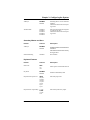
Floppy Drive Subsystem Group
Floppy Drive A Options
Micron Electronics, Inc.
3.5 inch 1.44/1.25 MB drive
5.25 inch
360KB drive
5.25 inch
1.2MB drive
3.5 inch
720KB drive
3.5 inch
2.88MBdrive
Disable or Not Installed
3-13
Micron NetFRAME LV2000 Server System User’s Guide
Floppy Drive B Options
Disable or Not Installed
3.5inch
1.44/1.25MB drive
5.25inch
360KB drive
5.25inch
1.2MB drive
3.5inch
720KB drive
3.5inch
2.88MB drive
IDE Subsystem Group
IDE Configuration - Primary Master
None
User
Auto
CD
IDE Drive Options - Primary Master
Multisector Transfer
Disabled, 2, 4, 8, or 16 Sectors
Standard CHS
Logical Block Addressing
Translation Mode
IDE Configuration - Primary Slave
None
User
Auto
CD
IDE Drive Options - Primary Slave
Multisector Transfer
Disabled, 2, 4, 8, or 16 Sectors
Translation Mode
Standard CHS
Logical Block Addressing
Automatic detection and enabling of IDE hard drives—during POST, if an
IDE controller is detected, the BIOS does the following:
❏
❏
❏
❏
Determines the types of IDE drives attached
Sets the drive parameters for the best performance
Maps each device into memory and I/O space
Assigns IRQs and DMA channels so there are no conflicts
If you choose parameters for your drive that are different from the drive’s
native parameters, your definitions will be programmed into the drive
controller.
To disable the IDE controller
If you plan to disable the IDE controller to reuse the interrupt for that controller,
you must physically unplug the IDE cable from the board connector (IDE0) if
a cable is present. Simply disabling the drive by configuring the SCU option
does not make the interrupt available for other use.
3-14
Micron Electronics, Inc.
Chapter 3: Configuring the System
Keyboard (KB) and Mouse Subsystem Group
Typematic Speed
30 CPS, 26 CPS, 21 CPS, 18 CPS, 13 CPS,
10 CPS, 6 CPS, 2 CPS
Mouse Control Option
Mouse Auto detected
Console Redirection
Console Redirection Control
COM Port for Redirection
Disable
Port Selection
Serial Port Baud Rate
2400
9600
19.2K
115.2K
Baud
Baud
Baud
Baud
Hardware Flow Control
None
CTS/RTS
CTS/RTS & Xoff/Xon
Select Terminal Type
IBM PC Extended ANSI/VT 100
Security Subsystems Group
Administrative Password Option
Disable/Enabled
Press <Enter> to display the Password
Menu. After entering a new password,
<Tab> down to verify the password.
New Password
Enter Password XXXXXXX
Verify Password XXXXXXX
User Password Option
Disable/Enabled
Press <Enter> to display the Password
Menu. After entering a new password,
<Tab> down to verify the password.
New Password
Enter Password XXXXXXX
Verify Password XXXXXXX
Hot Key Option
Disable/{Ctrl-Alt-?}
Press <Enter> to display menu:
Micron Electronics, Inc.
3-15
Micron NetFRAME LV2000 Server System User’s Guide
Disable
Enable
<Tab> down to Enable, and then <Tab>
to Enter New Hot Key. Type one
character, either a letter or number.
Lockout Timer
Disable
Press <Enter> to display menu of possible
choices.
Secure Boot Mode
Disable/Enable
Video Blanking
Disable/Enable
Floppy Writes
Enable/Disable
Security—the BIOS includes security features to prevent
unauthorized access to or tampering with the system. Once the
security features are enabled, access is allowed only after the correct
password has been entered. Enabling is implied if you set a password
here.
MultiBoot Group
Boot Device Priority
Menu for Boot Devices
MultiBoot Group—the sequence that you specify on the menu in the
MultiBoot Group will determine the boot order. If secure mode is
enabled (a user password is set), then you will be prompted for a
password before the system fully boots. If secure mode is enabled
and the “Secure Boot Mode” option is also enabled, the system will
fully boot but will require a password before accepting any keyboard
or mouse input.
SCSI ROM BIOS Options Group
SCSI-A ROM BIOS Scan
3-16
Enable
Disable (if disabled, the SCSI-A channel
is fully configured, but the ROM scan is
skipped) .
Micron Electronics, Inc.
Chapter 3: Configuring the System
Management Subsystem Group
System Sensor Control
Press <Enter> to modify the System
Sensors.*
System Management Mode
Enable/Disable
Event Logging
Enable/Disable
*Select and enter values to be used by server management software.
The options in the Management Subsystem Group are used to
❏
❏
❏
Set up system board voltage and temperature scanning by
determining the appropriate thresholds
Enable or disable a system speaker
Scan the flash memory area for binaries that extend or alter critical
event logging
This section does not list the sensors that will be displayed for configuring,
because the list depends on information provided by the system at run-time.
The information is placed in the system during manufacturing and assembly
and depends on the particular configuration of the system.
However, the user interface should be constant when viewed on a sensor-bysensor basis. The screen gives prompts for how to select and modify values
and how to move around the screen. For each available sensor control, the
display includes the choices shown below, with blanks for entering values by
using the <+> or <-> keys (“+5 V supply” is shown here as an example):
+5 V supply
Disable / Enable
Upper Fatal:
Upper Warning:
Lower Warning:
Lower Fatal:
In most cases, we recommend leaving the controls Enabled.
However, if you have an operating system that does not handle system
management interrupts, then you might want to disable the controls. When a
control is disabled, the sensor itself is still active and able to give valid readings,
but no system management interrupt will be generated. A server management
utility can collect the readings for information or comparison.
Micron Electronics, Inc.
3-17
Micron NetFRAME LV2000 Server System User’s Guide
System Management Options
System Management Mode*
Disable/Enable
Event Logging*
Disable
Enable (controls onboard event logging.)
PCI System Error Detection*
Disable
Enable
Reserved System Resources
* Enable all three options if you are using server management software.
System Management Mode—if enabled, the embedded Server Management
firmware is loaded.
Event Logging—if event logging is enabled, the BIOS can log critical and
informational events to nonvolatile flash memory. Critical events are those
that normally result in the system being shut down to prevent catastrophic
side-effects from propagating to other parts of the system. These are example
events:
❏ Operating system outside of the range of set temperature and
voltage limits
❏ Multibit and parity errors in the memory subsystem
❏ Most errors that normally generate a Nonmaskable Interrupt
(NMI) (including I/O channel check, software generated NMI,
and PCI SERR events)
When such errors are detected, the system management interrupt (SMI)
routines log the error or event (transparently to the OS) and cause an NMI to
be generated for certain fatal events (for example, certain NMIs and
uncorrectable ECC errors).
If the OS device driver is using the watchdog timer to detect software or
hardware failures, and that timer happens to expire, an Asynchronous System
Reset (ASR) is generated. This is equivalent to a hard reset, except that the
limit registers are not reset. POST detects this event as the system reboots and
will log the event to the logging area.
PCI System Error Detection—when enabled, if a PCI bus error (SERR#) is
detected, a critical event is placed in the system event log and an NMI is
generated. Enabling this feature has no effect when SMM Mode or Event
Logging is disabled.
3-18
Micron Electronics, Inc.
Chapter 3: Configuring the System
Server Management
The system board includes hardware components that process information
about system status and that monitor power supply voltages and operating
temperature. You can use server management software to send and log
messages about conditions reported if the system is not operating within
specified limits.
Some options are required by server management software
If you are using server management software, make sure you select these
options in the SCU and Setup; some of the options in the two utilities achieve
the same goal, although the menu text differs:
Enable or select this option in SCU
System Management Options,
System Management Mode
Enable or select this option in Setup
SMM Feature, System Management
submenu
Event Logging*
Event Logging, System Management
submenu
PCI System Error Detection
System SERR Detection, System
Management submenu, page 84
System Sensor Control**
*To view an event log, you must have server management software installed.
**The SCU contains menus for entering sensor control values (thresholds), and the BIOS
will load defaults from the SCU. Note that server management software may include
its own menus for entering threshold values, and these values may overwrite the ones
you enter using the SCU menus. For details, refer to the manual that comes with your
server management software.
Micron Electronics, Inc.
3-19
Micron NetFRAME LV2000 Server System User’s Guide
Using Setup
This section describes the BIOS Setup options. Use Setup to change the system
configuration defaults. You can run Setup with or without an operating system
being present. Setup stores most of the configuration values in battery-backed
CMOS; the rest of the values are stored in flash memory. The values take
effect when you boot the system. POST uses these values to configure the
hardware; if the values and the actual hardware do not agree, POST generates
an error message. You must then run Setup to specify the correct configuration.
Run Setup: you may run Setup to modify any standard PC AT= system board
feature such as:
❏ Select diskette drive
❏ Select parallel port
❏ Select serial port
❏ Set time/date (to be stored in RTC)
❏ Configure IDE hard drive
❏ Specify boot device sequence
❏ Enable SCSI BIOS
Run SCU, not Setup: you must run the SCU instead of Setup to do the
following:
❏ Add or remove any ISA board that is not Plug and Playcompatible
❏ Enter or change information about a board
❏ Set system management threshold values
❏ Alter system resources (such as interrupts, memory addresses,
I/O assignments) to user-selected choices instead of choices
selected by the BIOS resource manager
❏ Specify new values whenever you add or remove memory
3-20
Micron Electronics, Inc.
Chapter 3: Configuring the System
If You Cannot Access Setup
If the diskette drive is misconfigured so that you cannot access it to run a
utility from a diskette, you may need to clear CMOS memory. You will need
to open the system, change a jumper setting, use Setup to check and set diskette
drive options, and change the jumper back. For a step-by-step procedure, see
Chapter 5, under the heading, “CMOS Jumper.”
How to Enter and Start Setup
You can enter and start Setup under several conditions:
❏
When you turn on the system, after POST completes the memory
test.
❏
When you reboot the system by pressing <Ctrl+Alt+Del> while
at the DOS operating system prompt.
❏
When you have moved the CMOS jumper on the system board
to the “Clear CMOS” position (enabled); for the procedure, see
Chapter 5, under the heading “CMOS Jumper.”
In the three conditions listed above, after rebooting, you will see this prompt:
Press <F2> to enter SETUP
If the <F2> prompt does not appear
If the <F2> prompt does not appear, the display of the prompt has been disabled
in the SCU. You can enter Setup anyway by pressing <F2> right after the
system memory size is shown.
For the procedure to enable the prompt, see Chapter 7 under the heading,
“Press <F2> Key to Enter Setup: Prompt Does Not Display.”
In a fourth condition, when CMOS/NVRAM has been corrupted, you will see
other prompts but not the <F2> prompt:
❏
Warning: cmos checksum invalid
❏
Warning: cmos time and date not set
In this condition, the BIOS will load default values for CMOS and attempt to
boot.
Micron Electronics, Inc.
3-21
Micron NetFRAME LV2000 Server System User’s Guide
Setup Menus
Setup has six major menus and several submenus:
1. Main Menu
• Primary IDE Master and Slave
• Secondary Master and Slave
• Keyboard Features
2. Advanced Menu
• PCI Configuration
- PCI Device, Embedded SCSI
- PCI Device, Slot 1 - Slot 4
- PCI/PNP ISA UMB Region Exclusion
- PCI/PNP ISA IRQ Resource Exclusion
• Integrated Peripheral Configuration
3. Security Menu
• Set Supervisor Password
• Set User Password
4. Server Menu
• System Management
- Server Management Information
• Console Redirection
5. Boot Menu
• Boot Device Priority
• Hard Drive
6. Exit Menu
3-22
Micron Electronics, Inc.
Chapter 3: Configuring the System
Main Menu
Default values are bold in the following tables.
You can make the following selections on the Main Menu itself. Use the
submenus for other selections.
Feature
Choices
Description
System Time
HH:MM:SS
Sets the system time
System Date
MM/DD/YYYY
Sets the system date
Legacy Diskette A:
Disabled
360KB
1.2MB
720KB
1.44/1.25MB
2.88 MB
Selects the diskette type
Legacy Diskette B:
Disabled
360KB
1.2 MB
720KB
1.44/1.25 MB
2.88 MB
Memory Cache
Enabled
Disabled
CPU Speed Setting
233 MHz
266 MHz
300 MHz
333 MHz
Language
Micron Electronics, Inc.
English (US)
Spanish
Italian
French
German
Enables Pentium II processor
cache
To activate this field, see “System
Board Jumpers” in Chapter 2.
Note
Depending on your configuration,
this option may or may not be
available.
Selects which language BIOS
displays
3-23
Micron NetFRAME LV2000 Server System User’s Guide
Primary IDE Master and Slave
Feature
Choices
Description
Type
Auto
None
CD-ROM
User
Auto allows the system to attempt
auto-detection of the drive type.
None informs the system to ignore
this drive.
CD ROM allows the manual entry
of fields described below.
User allows the manual entry of all
fields described below.
Cylinders
1 to 2048
Number of Cylinders on Drive.
This field is changeable only for
Type User.
This field is informational only for
Type Auto.
Heads
1 to 16
Number of read/write heads on
drive.
This field is available only for Type
User.
This field is informational only for
Type Auto.
Sectors
1 to 64
Number of sectors per track.
This field is available only for Type
User.
This field is informational only for
Type Auto.
Maximum Capacity
N/A
Computed size of drive from
cylinders, heads, and sectors
entered.
This field is available only for Type
User.
This field is informational only for
Type Auto.
Multi-Sector Transfer
Disabled
2, 4, 8, or 16
sectors
Determines the number of sectors
per block for multi-sector transfers.
This field is informational only for
Type Auto.
LBA Mode Control
Disabled
Enabled
Enabling LBA causes logical block
addressing to be used in place of
cylinders, heads, and sectors.
This field is informational only for
Type Auto.
3-24
Micron Electronics, Inc.
Chapter 3: Configuring the System
32 Bit I/O
Disabled
Enabled
Enabling allows 32 bit IDE data
transfers.
This field is informational only for
Type Auto.
Transfer Mode
Standard
Fast PIO 1
Fast PIO 2
Fast PIO 3
Fast PIO 4
Selects the method for moving data
to and from the drive.
This field is informational only for
Type Auto.
Secondary Master and Slave
Feature
Choices
Description
32 Bit I/O
Disabled
Enabled
Enabling allows 32 bit IDE data
transfers.
This field is informational only
for Type Auto.
Smart Monitoring
Disabled
Not available.
Feature
Choices
Description
Num Lock
Auto
On
Off
Key Click
Disabled
Enabled
Keyboard auto-repeat rate
30/sec
26.7/sec
21.8/sec
18.5/sec
13.3/sec
10/sec
6/sec
2/sec
Keyboard auto-repeat delay
1/4 sec
1/2sec
3/4 sec
1 sec
Keyboard Features
Micron Electronics, Inc.
Selects power-on state for Num Lock
Enables or disables key click
Selects key repeat rate
Selects delay before key repeat
3-25
Micron NetFRAME LV2000 Server System User’s Guide
Advanced Menu
The Advanced Menu includes selections that take you to two other
configuration menus:
1.
PCI configuration, which includes the following submenus:
•
PCI Device, Embedded SCSI
•
PCI Device, Slot 1 - Slot 4
•
PCI/PNP/ ISA UMB Region Exclusion
•
PCI/PNP ISA IRQ Resource Exclusion
2.
Integrated Peripheral Configuration.
You can make the following selections on the Advanced Menu itself. Use the
submenus for the three other selections that appear on the Advanced Menu.
Feature
Choices
Description
Plug and Play OS
No
Yes
Select Yes if you are booting a Plug
and Play capable operating system.
Reset Configuration Data
No
Yes
Select Yes if you want to clear the
system configuration data during
next boot. System automatically
resets to No in next boot.
Use Multiprocessor
Specification
1.1
1.4
Selects the version of multiprocessor
specification to use. Some operating
systems require version 1.1.
Large Disk Access Mode
DOS
Other
Select DOS if your OS is DOS, or
Other for UNIX, Novell† NetWare†,
or other OS.
Enable Memory Gap
Disabled
Extended
Conventional creates a 128KB
system memory gap starting at
512KB.
Extended creates a 1MB extended
memory gap starting at 15MB.
Delay on Option ROMs
Disabled
Enabled
Forces a short delay at the end of
each Option ROM scan.
3-26
Micron Electronics, Inc.
Chapter 3: Configuring the System
PCI Configuration
The PCI Configuration Menu only contains selections that access other
submenus.
PCI Device, Embedded SCSI
Feature
Choices
Option ROM Scan
Enabled
Disabled
Enable Master
Enabled
Disabled
Latency Timer
Default
0020h
0040h
0060h
0080h
00A0h
00C0h
00E0h
Description
Enables option ROM scan of the
selected device.
Enabled selects the device as a PCI
bus master.
Minimum guaranteed time, in units
of PCI bus clocks, that a device may
be master on a PCI bus.
PCI Device, Slot 1 - Slot 4
Feature
Choices
Option ROM Scan
Enabled
Disabled
Enable Master
Enabled
Disabled
Latency Timer
Default
020h
040h
060h
080h
0A0h
0C0h
0E0h
Micron Electronics, Inc.
Description
Enables option ROM scan of the
selected device.
Enables selected device as a PCI bus
master.
Minimum guaranteed time, in units
of PCI bus clocks, that a device may
be master on a PCI bus.
3-27
Micron NetFRAME LV2000 Server System User’s Guide
PCI/PNP ISA UMB Region Exclusion
Feature
Choices
Description
C800 - CBFF
Available
Reserved
Reserves the specified block of upper
memory for use by legacy ISA
devices.
CC00 - CFFF
Available
Reserved
Reserves the specified block of upper
memory for use by legacy ISA
devices.
D000 - D3FF
Available
Reserved
Reserves the specified block of upper
memory for use by legacy ISA
devices.
D400 - D7FF
Available
Reserved
Reserves the specified block of upper
memory for use by legacy ISA
devices.
D800 - DBFF
Available
Reserved
Reserves the specified block of upper
memory for use by legacy ISA
devices.
DC00 - DFFF
Available
Reserved
Reserves the specified block of upper
memory for use by legacy ISA
devices.
PCI/PNP ISA IRQ Resource Exclusion
Feature
Option
IRQ 3, 4, 5, 7, 9, 10, 11, 15
Available
Reserved
3-28
Description
Reserves the specified IRQ for use by
legacy ISA devices.
Micron Electronics, Inc.
Chapter 3: Configuring the System
Integrated Peripheral Configuration
Feature
Choices
Description
Serial Port A
Disabled
Enabled
Auto
PnP OS
Auto forces BIOS to configure the
port.
PnP OS forces OS configures the
port.
Base I/O Address
3F8
2F8
3E8
2E8
Selects the base I/O address for
COM port A.
Interrupt
IRQ 4
IRQ 3
Selects the IRQ for COM port A.
Serial Port B
Disabled
Enabled
Auto
PnP OS
Auto forces BIOS to configure the
port.
PnP OS forces OS configures the
port.
Mode
Normal
IrDA†
ASK-IR
Selects serial port B mode.
Base I/O Address
3F8
2F8
3E8
2E8
Selects the base I/O address for
COM port B.
Interrupt
IRQ 4
IRQ 3
Selects the IRQ for COM port B.
Parallel Port
Disabled
Enabled
Auto
PnP OS
Auto forces BIOS to configure the
port.
PnP OS forces OS configures the
port.
Mode
Output only
Bi-directional
EPP
ECP
Selects parallel port mode.
Base I/O Address
378
278
Selects the base I/O address for LPT
port.
Interrupt
IRQ 5
IRQ 7
Selects the IRQ for LPT port.
Micron Electronics, Inc.
3-29
Micron NetFRAME LV2000 Server System User’s Guide
Feature
Choices
Description
DMA channel
DMA 1
DMA 3
Selects the DMA for LPT port.
Floppy disk controller
Disabled
Enabled
Enables onboard diskette controller.
Base I/O Address
Primary
Secondary
Selects base I/O address for diskette
controller.
PS/2 Mouse
Disabled
Enabled
Enables or disables onboard mouse.
Disabling the mouse frees up IRQ
12. If enabled, the OS can determine
whether to enable or disable the
mouse.
3-30
Micron Electronics, Inc.
Chapter 3: Configuring the System
Security Menu
You can make the following selections on the Security Menu itself. Enabling
the Supervisor Password field requires a password for entering Setup. The
passwords are not case sensitive.
Feature
Choices
Description
Administrator Password is
Clear
Status only; user cannot modify.
User Password is
Clear
Status only; user cannot modify.
Once set, this can be disabled by
setting it to a null string, or by
clearing password jumper on system
board (see System Board Jumpers in
Chapter 2).
Set Administrative Password Press Enter
When the <Enter> key is pressed,
the user is prompted for a password;
press ESC key to abort. Once set, this
can be disabled by setting it to a null
string, or by clearing password
jumper on system board (see System
Board Jumpers in Chapter 2).
Set User Password
Press Enter
When the <Enter> key is pressed,
the user is prompted for a password;
press ESC key to abort. Once set, this
can be disabled by setting it to a null
string, or by clearing password
jumper on system board (see System
Board Jumpers in Chapter 2).
Password on Boot
Disabled
Enabled
Requires password entry before
boot. System will remain in secure
mode until password is entered.
Password on Boot takes precedence
over Secure Mode Boot.
Diskette Access
Administrator
User
Controls access to diskette drives.
Fixed Disk Boot Sector
Normal
Write Protect
Write-protects boot sector on hard
disk to protect against viruses.
System Backup Reminder
Disabled
Daily
Weekly
Monthly
Displays reminder message at boot.
Micron Electronics, Inc.
3-31
Micron NetFRAME LV2000 Server System User’s Guide
Feature
Choices
Description
Virus Check Reminder
Disabled
Daily
Weekly
Monthly
Displays reminder message at boot.
Secure Mode Timer
Disabled
1 min
2 min
5 min
10 min
20 min
1 hr
2 hr
Period of key/PS/2 mouse
inactivity specified for secure mode
to activate. A password is required
for secure mode to function. Cannot
be enabled unless at least one
password is enabled.
Secure Mode Hot Key
(Ctrl-Alt- )
[]
[A, B, ..., Z]
Key assigned to invoke the
Quicklock feature. Cannot be
enabled unless at least one
password is enabled.
Secure Mode Boot
Disabled
Enabled
System will boot in secure mode.
The user must enter a password to
unlock the system. Cannot be
enabled unless at least one
password is enabled.
Video Blanking
Disabled
Enabled
Blank video when secure mode is
activated. The user must enter a
password to unlock the system.
Cannot be enabled unless at least
one password is enabled.
Floppy Write Protect
Disabled
Enabled
When secure mode is activated, the
diskette drive is write protected.
The user must enter a password to
disable. Cannot be enabled unless
at least one password is enabled.
Front Panel Lockout
Disabled
Enabled
When secure mode is activated, the
reset and power switches are locked.
The user must enter a password to
unlock the system. Cannot be
enabled unless at least one
password is enabled.
3-32
Micron Electronics, Inc.
Chapter 3: Configuring the System
Server Menu
The Server Menu includes selections that take you to two other configuration
menus:
1.
System Management
•
Server Management Information
2.
Console Redirection
You can make the following selections on the Server Menu itself.
Feature
Choices
Description
PCI IRQs to IO-APIC
mapping
Disabled
Enabled
If enabled, BIOS will describe direct
PCI interrupt connections to IO
APIC in multiprocessor table. Do
not enable if OS does not support
this feature.
PCI IRQ to External MUX
Disabled
Enabled
Routes PCI IRQs to external
multiplexer (MUX) and inputs
PIIX4. Disables PIIX4 MUX.
Processor Retest
No
Yes
If YES, BIOS clears historical
processor status and retests all
processors on next boot.
System Management
Feature
Choices
Description
I2C User Defaults
Disabled
If enabled, I2C user default settings
will be programmed.
System Management Mode
Disabled
Enabled
System Event Logging
Disabled
Enabled
Clear Event Log
No
Yes
Fault Resilient Booting
Disabled
Lvl-1
Lvl-2
Enabled loads the embedded server
management firmware.
When enabled, system events will be
logged by BIOS and BMC.
Yes clears the system event log.
Micron Electronics, Inc.
Determines level of Fault Resilient
Booting.
3-33
Micron NetFRAME LV2000 Server System User’s Guide
Feature
PERR Reporting
Choices
Description
Lvl-3
Disabled
SMI Only
SMI &NMI
If selected, system detects and
reports PERR on PCI buses.
SERR Reporting
Disabled
Enabled
Test Extended Memory
Enabled
Disabled
SMM Debug Mode
Enabled
Disabled
CPU Slot1 and Slot2
Presence
Enabled
Disabled
Enabled generates a PCI bus system
error report.
Diagnostic option only.
If enabled, the SMM outputs to
video and Port 80.
Enables or disables processor at
Slot1 or Slot 2.
Server Management Information
No items on this menu can be modified by the user. If items require changes,
consult your system administrator.
Console Redirection
Feature
Choices
COM Port Address
Disabled
3F8
2F8
3E8
IRQ #
3 or 4
Baud Rate
9600
19.2k
38.4k
115.2k
Flow Control
None
CTS/RTS
XON/XOFF
CTS/RTS + CD
3-34
Description
When enabled, console redirection
uses the I/O port specified.
When console redirection is enabled,
this displays the IRQ assigned per
the address chosen in the COM Port
Address field.
When console redirection is enabled,
use the baud rate specified.
None disallows flow control.
CTS/RTS is hardware flow control.
XON/XOFF is software flow
control.
CTS/RTS +CD is hardware plus
carrier-detect flow control.
Micron Electronics, Inc.
Chapter 3: Configuring the System
Boot Menu
The Boot Menu includes selections that take you to two other configuration
menus:
1. Boot Device Priority
2. Hard Drive
Items on the Boot Menu can be prioritized. Use the up or down arrow keys to
select a device, then press the <+> or <-> keys to move the device higher or
lower in the boot priority list.
You can make the following selections on the Boot Menu itself.
Feature
Choices
Description
Floppy Check
Disabled
Enabled
If Enabled, system verifies diskette
type on boot. Disabled results in a
faster boot.
Summary Screen
Disabled
Enabled
If Enabled, system displays system
configuration during boot.
Boot Device Priority
Boot Priority
Device
Description
1.
Diskette Drive
Attempts to boot from drive A:
2.
Hard Drive
Attempts to boot from a hard drive device.
3.
ATAPI CD-ROM Drive Attempts to boot from an ATAPI CD-ROM
drive.
4.
Diagnostic boot
Micron Electronics, Inc.
Attempts to boot from diagnostic boot
partition of the flash memory.
3-35
Micron NetFRAME LV2000 Server System User’s Guide
Hard Drive
For options on this menu, use the up or down arrow keys to select a device,
then press the <+> or <-> keys to move the device higher or lower in the boot
priority list
Option
Description
1. Other Bootable Device
N/A
2. WDC AC21600H
N/A
3-36
Micron Electronics, Inc.
Chapter 3: Configuring the System
Exit Menu
You can make the following selections on the Exit Menu. Select an option
using the up or down arrow keys, then press <Enter> to execute the option.
Pressing <Esc> does not exit this menu. You must select one of the items from
the menu or menu bar to exit.
Choices
Description
Exit Saving Changes
Exits after writing all modified Setup item values to
NVRAM.
Exit Discarding Changes
Exits leaving NVRAM unmodified.
Load Setup Defaults
Loads values of all Setup items from previously saved
custom defaults.
Load Custom Defaults
Loads default values for all Setup items.
Save Custom Defaults
Saves present Setup values to custom defaults.
Discard Changes
Reads previous values of all Setup items from NVRAM.
Save Changes
Writes all Setup item values to NVRAM.
Micron Electronics, Inc.
3-37
Micron NetFRAME LV2000 Server System User’s Guide
Using SCSISelect
The SCSISelect utility detects the number of AIC-7880 wide/fast-20 SCSI III
host adapters in the system. Use the utility to:
•
Change default values
•
Check or change SCSI device settings that may conflict with those
of other devices in the system
•
Perform a low-level format on SCSI devices installed in the system
How to Enter and Start SCSISelect
1.
Turn on your video monitor and system. After a few seconds
POST begins to run. After the memory tests are completed, if
you do not choose to enter Setup and you do have an operating
system installed, a SCSISelect prompt will appear. Record your
settings.
Press
<Ctrl><A> for SCSISelect(TM) Utility!
2.
Press <Ctrl+A> to run the utility. SCSISelect has these menus:
1.
Main Menu
• Configuration
- Boot Device Configuration
- SCSI Device Configuration
- Advanced Configuration Options
• SCSI Disk Utilities
2.
Exit Menu
To navigate the menus:
Press
Exit a menu or the utility
Select an item
Go to previous item
Go to next item
Reset to host adapter defaults
<Esc>
<Enter>
Up arrow
Down arrow
<F6>
3-38
Micron Electronics, Inc.
Chapter 3: Configuring the System
Main Menu, SCSISelect
The main SCSISelect menu shows the name of the host adapter and its address:
<Host adapter> at Bus:Device xx:xxh. There are two menu options.
Options
Comment
Configure/View Host
Adapter Settings
Press <Enter> to display the Configuration menu.
SCSI Disk Utilities
Press <Enter> to display the SCSI Disk Utilities menu.
The utility scans for all SCSI devices installed in the
system and lists them. Press <Enter> to select the device
you want to run utilities on.
The default ID for the SCSI host adapter is #7. If you
select the host adapter, you will see only a message stating
that fact; you cannot specify any options for the host
adapter from the utilities menu.
Configuration Menu, SCSISelect
Feature
Default
Choices
SCSI Bus Interface Definitions
Host Adapter SCSI ID
7
0 - 15
SCSI Parity Checking
Enabled
Enable/Disable
Host Adapter SCSI
Termination
Low ON/High
ON
Low ON/High ON
Low OFF/High OFF
Low OFF/High On
Boot Device Options
Press <Enter>
See Boot Device Options, SCSISelect.
SCSI Device Configuration
Press <Enter>
See SCSI Device Configuration,
SCSISelect.
Advanced Configuration
Options
Press <Enter>
See Advanced Configuration
Options, SCSISelect.
Additional Options
Micron Electronics, Inc.
3-39
Micron NetFRAME LV2000 Server System User’s Guide
Host Adapter SCSI ID—Each device on the SCSI bus, including the adapter,
must have a unique ID. The ID defines the device, and the priority of the ID
determines which device controls the bus when two or more devices try to use
it at the same time. Each adapter on the bus, whether 8- or 16-bit, has a default
ID of 7, so the adapter always has the highest priority. This is the priority
model:
Device priority model
Highest priority ID
Lowest priority ID
8-bit devices (narrow SCSI) 7
0
16-bit devices (wide SCSI)
15 through 8
7 through 0
(In this case, ID 7 has the
highest priority and
ID 8 the lowest)
SCSI Parity Checking—when enabled, the host adapter uses SCSI parity
checking to verify the accuracy of data transfer on the SCSI bus. If a device on
the bus does not support SCSI parity, the option must be disabled.
Host Adapter SCSI Termination—the setting for this option is determined
by (1) the location of the host adapter on the bus and (2) whether the SCSI
devices connected to the bus are narrow, wide, or a combination. The bus
must have a set of resistors, calledterminators, either installed in or enabled on
the first and last SCSI devices on the bus, or else data transfer may not be
accurate. The host adapter itself is the SCSI device at one end of the bus, and
termination on the adapter cannot be disabled. On a 16-bit adapter, termination
is enabled for both the low byte (bits 0-7) and the high byte (bits 8-15). If there
is no 8-bit adapter at the end of the bus, you must disable termination by using
the option in the SCSISelectConfiguration menu. This is the termination model:
Host adapter location
SCSI devices
connected to bus
Host Adapter SCSI
Termination choice
Installed at end of bus
only 8-bit, or
only 16-bit
Low ON/High ON (default)
Installed at end of bus
both 8-bit and 16-bit
Low ON/High ON (same as
default)
Note: Last device must be
16-bit and terminated.
Not at end of bus*
only 16-bit
Low OFF/High OFF
Not at end of bus*
both 8-bit and 16-bit
Low OFF/High On
*In this system, the host adapter on the system board is always at one end of the bus.
3-40
Micron Electronics, Inc.
Chapter 3: Configuring the System
Boot Device Options, SCSISelect
Feature
Option
Comment
Boot Target ID
0-15
The default boot device is at SCSI ID 0 with
logical unit number (LUN) 0. To specify a
different boot device, choose a different SCSI
ID (0 through 7 on 8-bit adapters, 0 through 15
on 16-bit adapters).
Boot LUN Number 0-7
The logical unit number (LUN) can be 0
through 7 (on 8-bit or 16-bit adapters).
If you disable Multiple LUN Support in the
Advanced Configuration menu, specifying a
number here has no effect.
Boot Target ID—The default boot device is the device at SCSI ID 0 with logical
unit number (LUN) 0. To specify a different boot device, choose a different
SCSI ID (0 through 7 on 8-bit adapters, 0 through 15 on 16-bit adapters).
Boot LUN Number—If the boot device has multiple logical units, you must
also specify the boot logical unit number (LUN). This can be 0 through 7 (on
8-bit or 16-bit adapters). Multiple LUN support can be disabled in the SCSISelect
Advanced Configuration menu.
SCSI Device Configuration, SCSISelect
The screen shows five features that can be configured independently for each
of up to 15 devices (SCSI Device ID #0 through #15)
Feature
Default
Choices
Initiate Sync Negotiation
Yes
Yes/No
Maximum Sync Transfer Rate 40.0 for 16-bit
20.0 for 8-bit
16-bit devices: 20.0, 26.8, 32.0, 40.0
8-bit devices: 10, 13.4, 16.0, 20.0
Enable Disconnection
Yes
Yes/No
Initiate Wide Negotiation
Yes
Yes/No
Send Start Unit Command
Yes
Yes/No
No effect if the BIOS is disabled.
Micron Electronics, Inc.
3-41
Micron NetFRAME LV2000 Server System User’s Guide
Initiate Sync Negotiation—when enabled (set to Yes), the host adapter initiates
synchronous negotiation with the SCSI device; when No, the adapter does not
initiate synchronous negotiation. Normally you should leave this set to Yes,
because the SCSI adapter and its attached devices can transfer data faster in
synchronous mode than in asynchronous. If a device does not support
synchronous negotiation, the adapter will automatically transfer data
asynchronously. If the device initiates synchronous negotiation, the host
adapter always responds accordingly.
Maximum Sync Transfer Rate—the setting determines the maximum
synchronous data transfer rate that the adapter will negotiate with the device.
If you have disabled (set to No) the Initiate Sync Negotiation option, the
maximum sync rate you select is the rate at which the adapter accepts data
from the device; there is no negotiation.
Enable Disconnection—when set to Yes, the adapter allows a SCSI device to
temporarily disconnect from the bus, and the adapter can continue to do other
bus operations. When no, the adapter does not allow a SCSI device to
disconnect.
•
Leave this set to Yes if there are two or more SCSI devices on the
bus
•
Change to No if there is only one SCSI device connected to the
bus (besides the adapter).
Initiate Wide Negotiation—when set to Yes, the adapter initiates wide
negotiation with each 16-bit SCSI device. You can leave this set to Yes even if
there are 8-bit devices connected; the adapter will not attempt wide negotiation
with 8-bit devices.
Send Start Unit Command—this option reduces the load on the system power
supply by allowing the host adapter to power-up SCSI devices one at a time at
boot time.
•
Yes is required for SCSI hard drives; the adapter sends the Start
Unit Command to each SCSI device individually to power-up.
•
When set to No, all SCSI devices power up at the same time. If a
device has been jumpered to wait for a start command, it will
not start.
If you enable the command for more than one device, the adapter sends the
command first to the boot device specified in the Boot Device Options menu.
After the first device responds, the adapter sends the command to the remaining
SCSI devices, beginning with the lowest SCSI ID.
3-42
Micron Electronics, Inc.
Chapter 3: Configuring the System
Do not enable the Send Start Unit option before checking...
Make sure the AIC-7880 BIOS option is enabled (see Advanced
Configuration Options).
Check the manual that comes with your SCSI device to make sure the
device supports the command. If so, it is likely that you will need to
change a switch or jumper setting on the device so it can respond to
the command.
Advanced Configuration Options, SCSISelect
Feature
Default
Choices
If you disable the Host Adapter BIOS option, the following options have no effect.
Host Adapter BIOS (Configuration
Utility Reserves BIOS Space)
Enabled
Enable/Disable
Support Removable Disks Under
BIOS as Fixed Disks
Boot Only
Boot Only
All Disks
Disable
Extended BIOS Translation for DOS
Drives greater than 1 GB
Enabled
Enable/Disable
Display <Ctrl-A> Message During
BIOS Initialization
Enabled
Enable/Disable
Multiple LUN Support
Disabled
Enabled/Disable
BIOS Support for Bootable CD-ROM
Enabled
Enable/Disable
BIOS Support for Int13 Extensions
Enabled
Enable/Disable
Support for Ultra SCSI Speed
Enabled
Enable/Disable
CAUTION, understand the options before changing defaults
Do not change the default settings in the SCSISelect Advanced
Configuration Options menu without understanding the
consequences of making changes.
Micron Electronics, Inc.
3-43
Micron NetFRAME LV2000 Server System User’s Guide
Host Adapter BIOS—The AIC-7880 BIOS must be enabled to allow these
actions:
•
Boot from a SCSI hard drive on the bus.
•
Enable any of the other options listed on the same menu
(Advanced Configuration Options).
•
Boot from a SCSI CD-ROM drive. If any IDE devices are selected
in the boot order, they will be chosen first over the SCSI device.
If the devices on the SCSI bus are controlled by device drivers and thus do not
need a BIOS, you can disable the option. This frees about 16 KB of memory
and shortens the boot time by up to 60 seconds. However, 2 KB of memory
space is still reserved per PCI and Plug and Play specifications.
Support Removable Disks Under BIOS as Fixed Disks (i.e., hard disks)—the
setting controls how removable-media devices are supported by the
AIC-7880 BIOS. The choices are:
Choice
Description
Boot Only (default)
Only the removable-media drive designated as the boot
device is treated as a fixed (hard) disk drive.
The AIC-7880 BIOS must be enabled.
All Disks
All removable-media drives supported by the AIC-7880
BIOS are treated as fixed drives. (If you are a NetWare
user: all removable-media drives are automatically
supported by NetWare as fixed disks regardless of how
you set this option.)
The AIC-7880 BIOS must be enabled.
Disabled
No removable-media drives running under DOS are
treated as fixed drives. Driver software is needed because
the drives are not controlled by the AIC-7880 BIOS.
CAUTION, do not remove media from drive under BIOS control
Do not remove media from a removable media drive if the drive is
under the control of the AIC-7880 BIOS.
3-44
Micron Electronics, Inc.
Chapter 3: Configuring the System
Extended BIOS Translation for DOS Drives > 1 GB—when Enabled, drives
handled by the AIC-7880 BIOS can use extended translation (255 heads,
63 sectors per track) if their formatted capacity is greater than 1 GB and standard
translation if smaller than 1 GB.
CAUTION, before changing option, back up hard disks!
First back up the hard disks if you need to change this setting and the
translation scheme! All data is erased when you change from one
translation scheme to another.
Display <Ctrl-A> Message During BIOS Initialization—if Enabled, at boot
time a prompt displays to let you run the SCSISelect program.
Multiple LUN Support—the default setting is Disabled. Enable the option if
any devices have multiple logical units.
BIOS Support for Bootable CD-ROM—when enabled, the system can boot
from a CD-ROM. The option displays only if the adapter BIOS is configured
to include it. To boot from a hard drive or other device, either disable this
option or make sure there is no bootable CD in the drive.
BIOS Support for Int 13 Extensions—when enabled, the adapter BIOS
supports Int 13h extensions, required for bootable CD-ROMs. The option
displays only if the adapter BIOS is configured to include bootable CD-ROM
support. You can disable the option if the boot device is not a CD-ROM, but it
does no harm to leave it enabled.
Support for UltraSCSI Speed—the default setting is Disabled. The option
displays only if the BIOS is configured to support UltraSCSI speeds. Enable
the option to use UltraSCSI speeds with the AIC-7880.
SCSI Disk Utilities Menu, SCSISelect
When you select SCSI Disk Utilities from the SCSISelect Main Menu, the utility
scans the SCSI bus for connected devices and lists the SCSI IDs and associated
devices on the bus.
From the list of devices, select the one you want to format or verify.
If a device has multiple logical units, a menu of LUNs appears.
Select the device you want to format or verify. A small menu appears. Select
Format Disk or Verify Disk.
Micron Electronics, Inc.
3-45
Micron NetFRAME LV2000 Server System User’s Guide
Utility
What it does
Comment
Format Disk
Does a low-level format on
the hard disk drive. Before
it starts, a prompt appears
asking you to confirm that
you want to format the
hard disk.
CAUTION
You cannot stop the formatting once
it starts! Do NOT answer yes unless
you intend to format the disk.
Verify Disk Media Scans the selected hard
disk for bad blocks and
prompts you to reassign
them.
You can press <Esc> at any time to
stop the verification task.
Exit Menu, SCSISelect
Feature
Option
Comment
Exit Utility?
Yes
No
When you finish configuring SCSI
devices, select “Yes” and press
<Enter>. This message appears:
“Please press any key to reboot”
3-46
Micron Electronics, Inc.
Chapter 3: Configuring the System
Installing Video Drivers
After configuring the system, you need to install video drivers to take full
advantage of the features of the onboard Cirrus Logic CL-GD5446 super VGA
video controller.
•
The Configuration Software CD includes video drivers for use
with DOS and Windows NT. Check the README.TXT file on
the CD for information on installing these drivers.
•
For other operating systems, see your OS instructions for
installing device drivers.
Configuring the Network Controller
This system includes the onboard Intel 82557 PCI LAN Controller. The IRQ
level and I/O address of the onboard controller are automatically set each
time you start the system. PCI systems automatically detect and configure
PCI-compliant adapters while booting.
For information about network software and configuration, refer to the
Configuration Software CD shipped with this system.
Micron Electronics, Inc.
3-47
s Guide
Chapter 4: Common Problems
Chapter 4
Common Problems
Introduction .............................................................................................. 4-2
Problems During Boot ........................................................................................ 4-2
System Problems ............................................................................................... 4-6
Hard Disk Problems ........................................................................................... 4-9
Micron Electronics, Inc.
4-1
Micron NetFRAME LV2000 Server System User’s Guide
Introduction
Occasionally while setting up and configuring a computer system, an error
may occur or an important element may be forgotten. This section provides
information regarding the most frequently encountered problems, as well as
many quick and simple solutions. If you continue to experience problems and
this section fails to provide solutions, please feel free to contact Micron technical
support (see Appendix A: Contacting Technical Support).
Problems During Boot
Problem
When the power switch is turned on, the system does not power up
(i.e., the exhaust fan does not run, the power indicator light is not
illuminated, the hard disk does not begin to spin, etc.), and no audible
"beep" is heard.
Possible Cause
❏ The power cable is unplugged or defective.
❏ Voltage switch is improperly set.
❏ No power at outlet.
❏ Bad power supply.
Solution Checklist
❏ Check to ensure the power cable is plugged in correctly and
firmly. Try a second power cable, if available, or test the cable
for continuity. Replace original cable if it is found to be defective.
4-2
❏
Check the red voltage switch (located at the rear of the unit near
the fan) and ensure that it is set for the proper voltage (115V in
the U.S. and Canada).
❏
Check the outlet with another appliance (e.g., a lamp).
❏
If a surge suppressor or Uninterruptable Power Supply (UPS) is
being used, temporarily bypass the surge suppressor and plug
the unit directly into the wall outlet. The surge suppressor or
UPS may be faulty.
Micron Electronics, Inc.
s Guide
Chapter 4: Common Problems
Problem
When the power switch is turned on, the system has power (i.e., the
exhaust fan runs, the power indicator light is illuminated, the hard
disk begins to spin, etc.), but the system appears dead. Generally the
keyboard LEDs will stay on.
Possible Cause
❏ The monitor may not be turned on or plugged in.
❏ A peripheral card may not be seated correctly on the system
board.
❏ A peripheral card may be defective.
❏ A floppy drive may be defective.
Solution Checklist
❏ Check to make sure the monitor power cable is plugged into the
wall outlet and the back of the monitor. Also verify the monitor
video cable is plugged into the video card in the back of the
computer. Check the monitor to ensure that the power is on. If
you suspect a problem with the monitor, please refer to the
manual that was provided with it.
❏
Carefully open the system unit. Press down firmly on all
peripherals in the expansion slots.
❏
With the system power shut off, remove one peripheral card,
power up the system, and wait a few moments to see if the
keyboard lights turn off. If they don’t turn off, repeat the above
steps with the next peripheral card until all have been removed.
After this has been completed, contact Micron technical support
for further assistance.
❏
With the system power shut off, completely disconnect one of
the floppy drives and power up the system. If the keyboard lights
do not turn off after a few moments, repeat the above procedure
until all drives are disconnected. After this has been completed,
contact Micron technical support for further assistance.
❏
Contact Micron technical support if none of the above procedures
is effective.
Micron Electronics, Inc.
4-3
Micron NetFRAME LV2000 Server System User’s Guide
Problem
System powers on, the display works, but the system does not
complete the boot process or you see one of the following error
messages:
“Hard Disk Controller Failure.”
“Fixed Disk Configuration Error.”
“Operating System Not Found.”
Possible Cause
❏ Hard drive is incorrectly set up in CMOS.
❏ Hard drive cable may not be properly connected.
❏ CMOS may have lost settings.
❏ SCSI controller card may have lost settings.
❏ Files on hard drive may be corrupted.
❏ Hard drive may be defective.
Solution Checklist
❏ If you have a SCSI hard drive, make sure that the CMOS says
Not Installed for all hard disk drives. For help in getting to your
CMOS settings, see Chapter 3 - The BIOS Setup Program.
4-4
❏
For an IDE drive - check the parameters of the hard drive. Have
the system re-Autodetect the settings of the drive. To do this,
highlight the first hard disk from the MAIN screen of your CMOS
Setup (labeled Primary IDE Master) and press the <Enter> key.
On the next screen press <Enter> again and select AUTO
CONFIGURED. Press <Enter> and the system should reassign
the proper values to the hard drive. You will also want to make
sure that the primary IDE controller is enabled. To verify, move
to the ADVANCED section of CMOS and press <Enter> on the
line that says PERIPHERAL CONFIGURATION. Press <Enter>
again and select AUTO. Exit and save your changes.
❏
With the power OFF, carefully open the system unit. Reset the
gray ribbon cable that is connected to the hard drive and to the
motherboard or SCSI Controller Card. To assist you, the colored
stripe going down the side of the gray controller cable signifies
pin one and should be connected to pin one of the controller and
drive. Also, check to ensure that the power connector in the Hard
Drive is secure. Power the system back up and perform an
AUTODETECT of the hard drive again.
Micron Electronics, Inc.
s Guide
Chapter 4: Common Problems
Problem
The system displays the error message “Non-system Disk or Disk
Error” or “Operating System Not found.”
Possible Cause
❏ The System files are missing from the Boot Sector of the hard
drive.
❏ The diskette in Drive A: is not bootable.
❏ CMOS is incorrectly configured.
Solution Checklist
❏ Your system is designed to first check the floppy drive for a
bootable diskette. If there is a diskette in the floppy drive when
you reset your system the above error message will appear unless
the diskette is a bootable system diskette. Remove the diskette
from drive A: and reboot your computer. If the computer still
does not boot up, you may have to restore system files to the
hard drive.
❏
To restore system files:
Make sure your hard drive information is correct in CMOS (see
above for help in correctly setting up your CMOS). Insert the
DOS or Windows 95 Boot Diskette provided with your Micron
system and either reset or power on your system with the disk
in the floppy drive.
❏
If you boot to a setup utility, exit out so that your computer is at
the A: prompt. From the A:\ prompt type SYS C:\ and press the
<Enter> key. Remove the Boot Diskette and reboot your system
by pressing the Reset button on the front of your PC.
Micron Electronics, Inc.
4-5
Micron NetFRAME LV2000 Server System User’s Guide
System Problems
Problem
A large number of damaged sectors are encountered when attempting
to format diskettes.
Possible Cause
❏
Typically, Micron computers are provided with a 1.44MB 3.5"
floppy drive. An attempt may have been made to format a lowdensity disk in one of the Micron high-density floppy drives.
Solution Checklist
❏ Please refer to the DOS manual for more information about how
to format low-density diskettes in high-density floppy drives.
Problem
The IDE CD-ROM is not being recognized by the system.
Possible Cause
❏ CMOS is configured incorrectly.
❏ The connection to the CD-ROM is improper or loose.
Solution Checklist
❏ Check in the system’s CMOS Setup to ensure that the
PERIPHERAL CONFIGURATION mode is set to Auto. For help
in getting to your CMOS settings, see Chapter 3 - The BIOS Setup
Program.
❏
4-6
With the power OFF, carefully open the system unit. Reconnect
the CD-ROM ribbon cable on the motherboard and at the back
of the CD-ROM. To assist you, the colored stripe going down
the side of the gray controller cable signifies pin one and should
be connected to pin one of the controller and drives. Also, check
to ensure that the power connector in the CD-ROM is secure.
Micron Electronics, Inc.
s Guide
Chapter 4: Common Problems
Problem
The system displays the error message COM Port 2F8 conflict during
boot, or the system beeps, and displays the message “Press F1 to
Continue, F2 for Setup.”
Possible Cause
❏ System CMOS has been reset to defaults, and you have a modem
installed on COM 2.
Solution Checklist
❏ Check that the modem settings are set correctly and not
conflicting with any other devices.
On Windows 95™ systems Serial/Com Port B should be set
to COM 4. For DOS and Windows for Workgroups™, Serial/
Com Port B should be set to Disabled or None. For help on
CMOS settings, refer to Chapter 3- The BIOS Setup Program.
❏
If you are using Windows 95™ and the CMOS is set correctly,
remove the checkmark from Use Original Configuration
(Current) under the properties section for your Communications
Port (Com 4) in device manager. Then, remove your modem from
device manager and have the Windows 95™ operating system
re-detect your modem.
Problem
The monitor is flickering noticeably or the video is distorted.
Possible Causes
❏ Interference
❏ Invalid or corrupt video drivers.
Solution Checklist
❏ Check for high power-draining devices, or high noise devices in
the area. Examples include heaters, air conditioners, other
monitors, other computers, fluorescent lights, printers,
microwaves, or televisions. Any of these devices could cause a
flickering in your display because of the interference they can
put into the power lines or the environment. Also, temporarily
unplug any other devices that are in the same outlet or surge
protector that the monitor and computer are using. This could
be amplified speakers, or one of the devices listed above.
❏
Temporarily switch your video display to use default standard
VGA drivers. Your display will not have the clarity or color
definition that it usually does, however, check to see if everything
appears normal. If it does, try reinstalling the video drivers
specific to your video card that shipped with your system, or
check the Micron Electronics Internet Site for updated video
drivers.
Micron Electronics, Inc.
4-7
Micron NetFRAME LV2000 Server System User’s Guide
Problem
After installing a new peripheral card, an unrelated part of the system
suddenly stops working.
Possible Cause
❏ The new card may be attempting to use some of the same system
resources, such as address space, I/O ports, interrupt lines, etc.,
and may be conflicting with the failing part of the system.
❏ When installing the new card, a different peripheral card or a
cable may have been knocked loose.
Solution Checklist
❏ Remove the new card and retry system.
If it works, you will need to change the I/O ports, interrupt lines
or address regions the new card uses. Most cards have jumpers
or switches that can be changed to reconfigure the settings. Refer
to the documentation that came with the card to determine how
to change the settings. If you have any questions, contact the
card’s manufacturer.
❏
4-8
Double check all the gray ribbon cables and power connectors to
ensure that they are plugged in correctly and securely.
Micron Electronics, Inc.
s Guide
Chapter 4: Common Problems
Hard Disk Problems
Problem
System has to be booted from a floppy disk. Hard drive is either
unrecognized or unreadable.
Possible Cause
❏ The connections between the drive and the controller may be
defective or loose.
❏
The hard drive’s root directory or file allocation table may be
corrupted. The controller or hard drive may also be defective.
Solution Checklist
❏ Check that the hard drive and controller are connected properly.
❏
If hard drive recovery software is available, use it to repair the
damage. The only other solution is to attempt a high-level (DOS)
format on the drive.
Do not attempt to low-level format the drive!
If the drive cannot be formatted, either the drive or the controller
may be defective. Contact Micron technical support.
Problem
System has to be booted from a floppy disk. Hard disk is completely
functional, but cannot be used for boot-up.
Possible Cause
❏ The hard drive’s boot sector may be corrupted.
Solution Checklist
❏ If hard drive recovery software is available, attempt to use it to
repair the damaged boot sector. The only other solution is to
attempt a high-level (DOS) format on the drive and transfer the
DOS system to the boot sector.
Do not attempt to low-level format the drive!
Backup your data before formatting your drive.
Micron Electronics, Inc.
4-9
Micron NetFRAME LV2000 Server System User’s Guide
Problem
Read/write, sector, data, or seek errors occur when attempting to
access files on the hard drive.
Possible Cause
❏ The format may be fading.
❏ The hard drive may be developing media errors.
❏ The file allocation table may be corrupted.
Solution Checklist
❏ Using a file-by-file backup method, backup as much data as you
can, then reformat the drive. If the format is successful, use a
disk diagnostic software application to test the media of the drive
(make sure the application locks out any errors it finds to make
them inaccessible from DOS). Finally, restore your files from the
backup tape or diskettes.
4-10
Micron Electronics, Inc.
Appendix A: Contacting Technical Support
Introduction
If you are experiencing problems with your Micron system and Chapter 4,
"Common Problems" does not provide the information needed to correct your
problem, feel free to contact Micron Technical Support at 1-800-877-8856.
Additional areas of support may be found by contacting the Micron Technical
Support BBS at 1-800-270-1207, Technical Support Internet Mail:
[email protected], Compuserve: GO MICRON or GO
PCVEND-21, and Micron Electronics Home Page: http://
www.mei.micronpc.com. But before you do, take a few minutes to read this
section for information about the equipment and information you might need
to help the technical support representative diagnose the problem.
Before You Call
Before contacting Micron Technical Support, please follow the next few steps.
These steps are designed to prepare you for any of the questions the technical
support representative might ask or any procedures he or she may need you
to do. This will help solve your problem in the shortest possible time.
1. Make sure your system is plugged into a grounded power outlet.
2. Locate the failing system as near a telephone as possible, preferably
close enough so that you can simultaneously talk with the technical
support representative while you work on the system.
3. Have a medium- to small-sized Phillips-head screwdriver available.
It’s possible you may need to open your system to correct the
problem.
4. Write down all error information you can remember, including
error messages, software used (with version numbers), and other
relevant information.
We hope Micron Technical Support will be able to solve your problem over
the telephone. However, in extreme cases, your system may need to be returned
to Micron Electronics, Inc. for repair. The next section describes what to do if
this is the case.
Micron Electronics, Inc.
A-1
Micron NetFRAME LV2000 Server System User’s Guide
Returning Equipment to Micron Electronics
If it is determined that your system needs to be returned to Micron for repair
or replacement, please observe the rules listed below. Failure to follow any of
these rules may result in long delays in repair or the simple return of the
system without repair.
1.
Contact Micron Technical Support at 1-800-877-8856 to obtain
an RMA (Return Material Authorization) number and to obtain
shipping instructions before returning any portion of your
system.
2.
Make sure all printed-circuit boards or static-sensitiveperipherals
are completely enclosed in anti-static bags or foam.
3.
Print the RMA number in large, legible numbers in black ink on
the outside of the shipping boxes.
4.
Enclose a note describing the problem as well as the name of the
technical support representative who authorized the return.
Micron also highly recommends that you follow these additional steps for
your protection:
1.
Make a complete backup of your hard drive(s) before returning
the system.
2.
Use the original packing material that came with your system.
Please ship to the following address:
Micron Electronics, Inc.
Attn: RMA #xxxx
1400 Shilo Drive
Nampa, ID 83687
A-2
Micron Electronics, Inc.
Appendix B: POST and BOOT Messages
POST and Boot Messages
POST (Power On Self Test) has two kinds of messages; those messages are the
Error message and the Informational message. The following tables list these
messages, their causes, and their solutions.
Table B-1. Post and Boot Messages
Micron Electronics, Inc.
B-1
Appendix C: Glossary
Glossary
Application: A software program that operates under an operating system to perform
a specific task.
BIOS:
Basic Input/Output System. Programs that are permanently stored ithe
system board’s ROM chips providing functions such as the power-on self
test. Also see ROM.
Boot:
To start the computer system and load the operating system.
Bus:
The set of address or data lines used to transfer information between different
components within a computer (such as memory, the microprocessor, and
the expansion slots).
Cache:
Provides fast, local storage for frequently accessed instructions and data to
provide the processor with the fastest stream of information possible, while
keeping main memory current.
Clock:
A circuit that sends a consistent, periodic signal used to synchronize the
computer and to step information through the system.
Closed:
A circuit that is complete. Usually accomplished by placing a jumper over
two pins on the system board or a peripheral card. Also see “Open” and
“Jumper.”
CMOS:
Complementary Metal Oxide Semiconductor. A logic circuit family that uses
very little power. Sometimes used to store information by applying constant,
uninterrupted power through the use of an external battery.
Co-processor: A microprocessor device that performs specialized computations (such
as floating-point arithmetic) much more efficiently than the microprocessor
alone.
CPU:
Central Processing Unit. The integrated circuit chip that performs the actual
computing functions of the computer. Other chips perform support functions
like storing data and controlling peripherals. Also see microprocessor.
Disk:
See “Floppy Disk” and “Hard Disk.”
DMA:
Direct Memory Access. A method for transferring data directly to and from
system memory, bypassing the microprocessor.
DOS:
See “Operating System.”
Micron Electronics, Inc.
C-1
Micron NetFRAME LV2000 Server System User’s Guide
DRAM: Dynamic Random Access Memory. Memory that requires a periodic refresh
cycle to keep the stored information from being lost. Loss of power causes
loss of data in this memory.
EISA:
Extended Industry Standard Architecture.
Expansion Slot: A connector on the motherboard for holding a peripheral card.
Floppy Disk: A 3.5 inch or 5.25 inch removable storage medium used for storing
programs and files externally from the computer system.
Format: A process that prepares a disk to hold data. For hard disks, there are two
formatting process: low-level and high-level.
Hard Disk: An internal or external, high-capacity, high-storage medium.
Hertz (Hz): A unit of frequency equal to one cycle per second.
I/O Port: A connector that allows external and some internal peripherals to
communicate with the computer system (e.g., serial ports and parallel ports).
I/O:
Input/Output. A generic term that refers to the devices and processes involved
in the computer’s reading and writing data.
IDE:
Integrated Drive Electronics. Currently the most popular type of hard drive
used in PCs. A standard IDE adapter can handle a maximum of two hard
drives.
Integrated Circuit: An electronic device that combines thousands of transistors on a
small chip of silicon or other semiconductor. Such devices are the building
blocks of computers.
Interface: The connection between the computer and its human operator, or between
the computer and peripheral device.
ISA:
Industry Standard Architecture. The standard bus interface that was
implemented in the IBM AT.
Jumper: On a printed circuit board, a patch cable or wire used to establish a circuit.
LBA:
Logical Block Addressing. Allows the system to address more than 528MB
on the hard drive.
Megahertz (MHz): A frequency of 1 million cycles per second.
Memory: Devices used to hold information and programs while they are being accessed
by the microprocessor. See also RAM and ROM.
Microprocessor: An integrated circuit that contains the circuits the computer needs to
calculate and to communicate with the other parts of the system. See also
CPU.
Modem: A device designed to allow computers to communicate over standard phone
lines.
C-2
Micron Electronics, Inc.
Appendix C: Glossary
Motherboard: See “System Board.”
Non-Volatile Memory: Memory that is maintained even when power is not on.
On-Board Floppy: A floppy disk drive controller that is incorporated into the system
board.
Open:
A circuit that is not complete. Usually accomplished by removing a jumper
from two pins on the system board or a peripheral card. Also see “Closed”
and “Jumper.”
Operating System: The software the provides a link between application programs
and the computer hardware (e.g., disks, memory).
PCI:
Peripheral Component Interface. A form of local bus architecture that provides
high-speed interconnection without directly interfacing with the processor.
Page Mode: Special function in DRAM that saves up to about 30% in cycle time by not
re-loading RAS bits.
Page:
Sections of memory consisting of sets of consecutive bytes. Pages begin on 4KB boundaries.
Peripheral Card: A printed circuit board that gives the computer added capability,
such as more memory or control of a new device. A card plugs into one of
the expansion slots located on the system board.
Peripheral: Any device that is connected to the computer system (e.g., printers,
keyboard, plotters, etc.).
Pin:
Any of the leads on a device, such as an integrated circuit, that plug into a
socket and connect to a system.
POST (Power On Self Test): Check-out procedures that the BIOS runs automatically
when the system is turned on. These procedures verify that all computer
hardware is functioning properly. If the test detects problems, the computer
displays error codes before (or instead of) starting the operating system. The
error codes can help a service person determine what is wrong with the
computer.
Program: A set of instructions that a computer interprets to perform some task. Also
see “Application” and “Operating System.”
RAM:
Random-Access Memory. The type of computer memory that can be used to
store information while a program is running. RAM consists of a number of
small integrated circuits that are plugged into the system board or an external
memory card.
ROM:
Read-Only Memory. The type of computer memory that is used to
permanently store the information vital to computer operation, including
some parts of the operating system. ROM is permanent and the contents will
not be lost when the computer is turned off.
Micron Electronics, Inc.
C-3
Micron NetFRAME LV2000 Server System User’s Guide
Setup Program: Used to inform the computer about installed peripheral, memory,
configuration information, date and time, etc.
Shadow RAM: A method of copying BIOS routines from slower ROM chips to much
faster RAM, increasing system performance.
SIMM:
Single In-line Memory Module. A small circuit board containing memory
components that plugs into special sockets located on the system board for
upgrading the system memory. These modules generally need to be inserted
in groups of two or four.
Software: A general term that describes a program or set of programs.
SRAM:
Static Random Access Memory. Does not require periodic refreshing that
dynamic memory requires.
System Board: The large printed-circuit board in a computer on which most electronic
devices are mounted; the primary board in a computer. All other interfaces
receive control signals or information from the motherboard. Also commonly
referred to as the “mainboard” or “motherboard.”
System Unit: The description for the computer case and all internal components (e.g.,
the system board, expansion cards, disk drives, power supply, etc.).
System: The assembly of basic components (e.g., power supply, motherboard, memory,
video monitor, etc.) united by some form of communication to form an
organized whole.
VESA:
Video Electronics Standard Association. A group of standards developed for
the purpose of defining video resolutions greater than VGA.
VGA:
Video Graphics Array. The most widely accepted graphics hardware standard
and the lowest common denominator for all graphics cards and monitors
manufactured to date.
Wait State: A delay in the computer’s information processing cycle caused by a
difference in speed between a faster processor and slower memory. A 0-wait
state means the processor does not have to “wait” for memory, and can access
data as fast as needed.
Write Precompensation: In a hard disk, the varying of the timing of the read/write
head current on the inner tracks of the disk to maintain a constant signal.
C-4
Micron Electronics, Inc.
Appendix D: Installing Sound Drivers
Installing Sound Device Drivers
This explains how to install the sound drivers necessary to utilize the onboard
sound support. Prior to installing any drivers, follow the instructions on how
to install a CD-ROM drive and how to connect external sound devices.
About Device Drivers
Device drivers are necessary for the computer system to communicate with
devices such as CD-ROM drives, sound controllers, graphics adapters or
devices that are not natively supported by the system BIOS. Once started, device
drivers remain active in the background of the computer system. Usually a
device driver is added to the CONFIG.SYS file, the AUTOEXEC.BAT file or
both.
WARNING:
This installation procedure should only be used if your hard drive
has been re-formatted. These drivers have been installed at the
factory and do not need to be reinstalled on a new system.
Installing the Sound Drivers
Once you have connected your external sound devices, you can install the
sound drivers. If you are installing a CD-ROM drive, it is recommended you
install it before setting up the sound devices.
1.
If you previously installed another sound card, remove it and
all associated files from your AUTOEXEC.BAT and CONFIG.SYS
files.
2.
Start your computer system.
3.
Insert the sound driver disk into your floppy drive.
4.
From the DOS prompt (C:\), type: A:\INSTALL
5.
Follow the on-screen instructions and the installation program
will automatically copy the drivers to your hard drive.
6.
Once the software is copied, the install program automatically
updates your CONFIG.SYS and AUTOEXEC.BAT files.
Micron Electronics, Inc.
D-1