1
Camcorder
Connections
Back of "IV
AUDIO
HI-FI
i
I_V
OUT SELECT OUT
Audio
o,
0UT Jack
IAudio/Video Out)
----II. /
"_.n_
Output
Adapter
r-_
L._
lusue,vsupplied
I
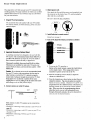
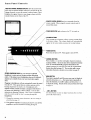
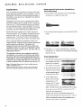
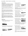
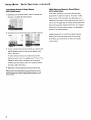
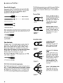
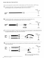
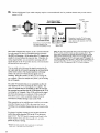
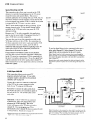
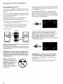
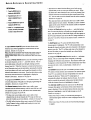
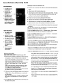
This connection allows you to play back tapes in the
camcorder and watch them on the TV.
S-VHS
,,._
-Hi
Cable
{_)
.
o):
(sometimes
V,0EO
_
CONVERTER
':::
2
1
SELECT
OUT
a separate cable that
attaches directly to
camcerderl
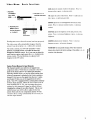
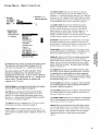
,An S-VHS or standard camcorder can be connected directly to
your TV. If you have an S-VHS camcorder, connect the S-VHS
video cable to the S-VIDEOconnector on your TV. If you have a
standard VHS camcorder, connect the video cable to the VIDEO
INPUT1jack on the back of your TV. With either video
connection, attach the audio cable to the INPUT1R/MONO
audio
jack.
Notes: When the adapter's S-VtlS cable is connected to the S-WDeO
connector, the Video plug docs not have to be connected.
Howcvcr, you
may prefer to plug it in anyway to kelp it out of the way. 'Fhc S-VIfS
video will automatically overrid e the VIDEO
tNPOT1 signal when you select
Channel 90.
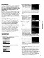
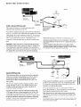
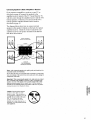
Operation: If the camcorder, is connected to the VIDEOINPUT1 .
jack (instead of the S-VIDEO
Connector), select TV channel 91 to
view whatever the camcorder is playing. If the camcorder is
connected to the S-VIDEO
connector and INPUT1AUDIOjack, select
TV channel 90 to view whatever the camcorder is playing.
Bottom
_
wi,hC
.....
derlI
/
S-VHS or StandardVHS Camcorder
ANTA
3_
_:_/M_0
_
Be sure to connect the video cable, however, if.you plan to usethe
camcorder for picture-in-picture
viewing or if you plan to use the SELECT
0UTjack for recording. •When recording from the SEt,dr O0Vjack, tune the
TV to channel 91 to see'the signal from the camcorder.
of Can_onler
AUDIO
_...............
©
|Usually supplied With
AV IN Jack
(Audio/Video In)
.
/
eameorder)
•
AudioNideo Input Cable
" _'_.__
Audio
IN_J;_I
o!
"
Video
"
CABLE/ANTENNA
.
Standard VHS Camcorder
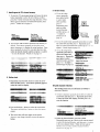
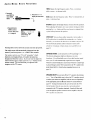
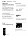
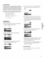
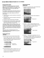
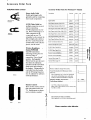
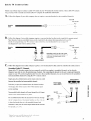
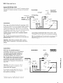
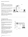
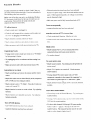
This connection allows you to record onto the camcorder
whatever is currently being displayed On the TV screen.
You'll also be able to record signals from a•VCR (or
similar device)that is connected to the TV's. INPUT1 or
INPUT 2 jacks.
The TV must remain turned on during recording. If you
change channels on the TV, the channel change will be
recorded on the camcorder tape unless you pause the
camcorder •during recording.
You may also want to use this connection to dub•or editVCR tapes with two or three camcorders (or VCRs). By
connecting one camcordcr (or VCR) to the INPUT1jacks
and•another camcorder (or VCR) to the INPUT2jacks, you'll
be able to selectively edit and record whatever is playing
on the TV screcn onto a third camcorder connected as
shown here to the SELECT
OUTjacks.
•.
•'
_'Ptrrz _
.
.@t
.
ANTA
......
v,ota
_
,
...................
CONVERTER
__
--3NFUr_
"i"
"2_
0UT
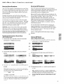
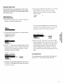
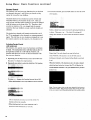
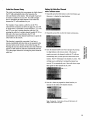
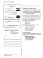
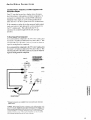
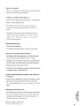
If you connect a surveillance system to your m0nitor; you'll
be able to record what the camcorder is displaying on the
TV screen by connecting another camcorder (or VCR ) to
the SELECT
OUTjacks as shown here.
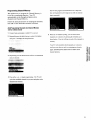
To see the signal from a device connected to the INPUT1
jacks, select channel 91. Select channel 92 to see the signal
from a device connectedto the wPOV2jacks.
Note: Signals from the S:VIDEOconnector do not come thru the SELECT
OUTviDeo jack. To record from an S-VHS component, rcmcmber to also
connect its regular video cable to the VIDEOINPUT1jack and then tune to
channel 91.
.' •
The small inset picture front the picturc-in-pic!ure
feature and any nt<?nus
(video, audio, or setup) or disphtys such as clock and channel that are on
the screen can not bc recorded.
43
.