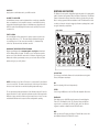
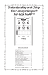
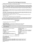
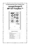
1
A
VC
U
VOL
EG
ER
FILT 320Hz
O2
VC
80H
5KH
z
z
20H
FRE
MID
I
FIN
N
E TU
OFF
CUT
AM
N
OU
20K
HZ
PE
LO
VE
EN
GLID
FILT
VCO
2 LV
PLIF
SUS
DEC
CK
A
ATT
RAT
E
OL
FO
AM
T
VC
F LF
OA
MT
ATE
GLID
IER
L
L
1 LV
D
MO
ER
ER
AM
MIX
LFO
SE
EA
REL
RES
Q
VC
/
z
E
VCO
ME
T
AY/
REL
EAS
E
TAIN
E
MINITAUR
Congratulations on your new Minitaur Analog Bass Synthesizer, a powerful, compact
IMPORTANT SAFETY INSTRUCTIONS
PLEASE READ BEFORE USING THIS PRODUCT
When using the Minitaur, these basic precautions should always be followed.
Moog synthesizer with a classic one knob per function design. At only 8.5" x 5.25"
and less than 3lbs, the Minitaur puts legendary analog Moog bass into a package
designed to fit seamlessly into all of your performance and production environments.
The Minitaur will bring you many happy years of creative and sonic enjoyment. We
are sure you are anxious to start playing, so refer to the “Getting Started” guide or look
over the Setup and Connections section to get going. At some point, we encourage
you to spend some time with this manual to discover all that the Minitaur has to offer.
Don’t forget - Experimentation and learning will reward you with a lifetime of
rich synthesizer experiences.
1. Read all the instructions before using this product.
2. Do not use the Minitaur near water.
3. This product, in combination with an amplifier and headphones or speakers,
may be capable of producing sound levels that could cause permanent
hearing loss. Do not operate for a long period of time at a high volume level
or at a level that is uncomfortable. If you experience any hearing loss or
ringing in your ears, you should consult an audiologist.
4. Keep the Minitaur away from heat sources such as radiators, heat registers,
and other products that produce heat.
5. The product should be connected to a power supply only of the type
described in the operating instructions.
6. The power supply should be unplugged from the outlet when left unused
for long periods of time.
7. Care should be taken so that liquids are not spilled into the front panel.
8. The Minitaur should be serviced by qualified personnel when:
a. Objects have fallen, or liquid has been spilled onto the product.
b. The product has been exposed to rain.
c. The product does not appear to operate normally or exhibits
a marked change in performance.
d. The product has been dropped or the enclosure damaged.
!
DANGER -- INSTRUCTIONS PERTAINING TO RISK OF FIRE, ELECTRIC
SHOCK, OR INJURY TO PERSONS: Do not open the chassis. There are no
user serviceable parts inside. Refer all servicing to qualified personnel only.
CONTENTS
UNPACKING AND INSPECTION
THE BASICS
CHECK THE CONTENTS IN THE SHIPPING CARTON
The Minitaur is shipped with the following items:
Unpacking & Inspection•••••••••••••••••••••
4
Setup and Connections••••••••••••••••••••••
4
Overviews and Features•••••••••••••••••••••
6
1. The Minitaur Analog Bass Synthesizer
Signal Flow••••••••••••••••••••••••••••••••••• 8
2. A 12VDC Power Adaptor
Basic Operation••••••••••••••••••••••••••••••
3. A “Getting Started” Guide
9
4. Registration Card
THE COMPONENTS
Oscillators•••••••••••••••••••••••••••••••••••• 9
Glide•••••••••••••••••••••••••••••••••••••••••• 11
Mix•••••••••••••••••••••••••••••••••••••••••••• 11
Filter•••••••••••••••••••••••••••••••••••••••••• 12
Envelopes••••••••••••••••••••••••••••••••••••
14
Release••••••••••••••••••••••••••••••••••••••• 15
Modulation•••••••••••••••••••••••••••••••••••
16
Volume•••••••••••••••••••••••••••••••••••••••
17
Input/Output Panel••••••••••••••••••••••••••
18
WHAT YOU WILL NEED
1. A MIDI keyboard or MIDI controller
2. A MIDI cable
3. A USB cable to connect the Minitaur to a host computer (for USB MIDI)
4. A 1/4” instrument cable and amplifier, or a pair of headphones with
an 1/8” plug
MIDI OPERATIONS
MIDI CC Table••••••••••••••••••••••••••••••••
22
APPENDICES
A. MIDI Implementation Chart••••••••••••••• 25
B. Service & Support Information•••••••••••
26
C. Caring for Minitaur•••••••••••••••••••••••
27
D. Using the CP-251 with Minitaur•••••••••••
27
E. Specifications••••••••••••••••••••••••••••
29
SETUP AND CONNECTIONS
NOTE: We encourage you to read the entire manual at some point to learn
more about the instrument and gain a better understanding of what you
can do with the Minitaur.
SET UP
Use care when unpacking your Minitaur, and be sure to save the carton and
all packing material in case you need to ship it for any reason.
CONNECT TO POWER & MIDI
Connect the supplied Power Adaptor to the Minitaur’s 12VDC power jack on the
back of the unit. The Minitaur’s universal power supply will operate with a
power source from 100 to 240 Volts AC, 50/60Hz. Using a 5 Pin MIDI cable,
make the connection between MIDI OUT of your MIDI controller and the MIDI
IN on the Minitaur. The Minitaur is set to receive messages on MIDI Channel 1, so
make sure your controller is set to transmit on MIDI Channel 1. If you are using
USB MIDI, connect the USB cable from the Minitaur to a USB port on your
computer. The Minitaur’s USB drivers are automatically installed, and it will appear
as ‘Moog Minitaur’ (Mac OSX or Win 7) or ‘USB Audio Device’ (Win XP) in the
MIDI Device selection options of your computer’s MIDI software.
4
POWER UP
Apply power to the Minitaur and to your MIDI controller.
CONNECT TO AMPLIFIER
Set the Minitaur’s volume control to minimum before connecting to an amplifier,
mixer, or headphones. Set the amplifier volume to a comfortable listening
level, and then slowly bring up the volume on the Minitaur as you play a few notes.
NOTE: Use caution when adjusting initial volume levels, especially if connected
to a subwoofer.
OVERVIEW AND FEATURES
The Minitaur is a monophonic Analog Bass Synthesizer with a 100% analog audio
path. It is based on the legendary Taurus I and Taurus 3 Synthesizers. The Minitaur
features 2 ultra-stable voltage controlled oscillators, a genuine Moog low pass
filter, 2 envelope generators and a modulation circuit. The Minitaur has a classic
one knob per function design in a rugged performance package that is small
enough to take with you anywhere.
FRONT PANEL
START PLAYING
Since the Minitaur is a Bass Synthesizer; it operates exclusively in the lower
note range (MIDI notes 0 - 72). This means that the Minitaur will respond
to your playing from ‘C4’ (an octave above middle ‘C’) downward. Play
some notes, tweak some knobs and have some fun!
DOWNLOAD THE MINITAUR EDITOR PROGRAM
Register your Minitaur online at www.moogmusic.com/register to download
the free Minitaur Editor Program. This allows you to load and save patches
and access all of the Minitaur’s under the hood features. Registering your
Minitaur also initiates your warranty, ensures you receive the latest software
updates, and gets you a nifty sticker!
OSCILLATORS
Two Voltage Controlled Oscillators with selectable Sawtooth (original
Taurus) and Square waveshapes.
NOTE: A warm up period of about 15 minutes is recommended for the Minitaur
to reach concert pitch. The warm up period may be a little longer if the Minitaur
has been stored outside the recommended operating temperature range.
The recommended operating temperature of the Minitaur is between 50 and 100
degrees Farenheit. It is safe to operate the synthesizer outside of this range, but the
Minitaur’s voltage controlled oscillators may not remain in tune. It is also recommended that the Minitaur not be exposed to direct sunlight while operating.
MIX
Mixer for adjusting VCO levels independently.
FILTER
Classic Moog 24dB/Octave Low Pass Filter with adjustable Resonance.
ENVELOPES
Twin Minimoog style ADSR Envelope Generators for modulating the
Filter (VCF) and Amplifier (VCA). The Envelope Decay and Release
segments are controlled by the DECAY knob, while the Release
segment is enabled or disabled via the RELEASE switch.
MOD
MIDI-syncable Low Frequency Oscillator (LFO) with Rate control and
and individual VCO and VCF AMOUNT controls.
5
6
SIGNAL FLOW
BACK PANEL
To understand how the Minitaur generates sound, take a look at the diagram
below. It shows the flow of Audio, Control Voltage and Modulation signals in
the Minitaur. Heavy lines indicate audio signals, which flow from left to right.
Lighter lines indicate Control Voltages (CV’s), which flow from the top and
from the bottom. Dotted lines indicate Modulation routings.
AUDIO INPUT
PITCH CV INPUT
FILTER CV INPUT
VOLUME CV INPUT
HEADPHONE OUT
1/8” Stereo Headphone Output.
AUDIO OUT
1/4” Unbalanced Output.
OSCILLATORS
MIX
CONTROL INPUTS
Analog control inputs for Pitch, Filter, Volume and Gate. Use control
voltage or a Moog EP2 expression pedal to connect and control the
Minitaur with everything from Moogerfoogers to modular systems.
2
/
VOLUME
AUDIO
OUT
HEADPHONES
ENVELOPES
MODULATION
(LFO)
FILTER
ADSR
PITCH CV
MIDI
DIN MIDI and USB MIDI offer complete control of the Minitaur’s sound engine.
VCA
(AMPLIFIER)
/
1
AUDIO IN
External Audio Input for processing audio through the Mixer and Filter
section of the Minitaur.
FILTER
VOLUME
ADSR
GATE
MIDI IN >
MIDI/CV CONVERTER
GATE INPUT
The Minitaur’s source signals are created by two Voltage-Controlled Oscillators (VCO) which are mixed with the External Audio Input. The Mixer
Output is routed to the Filter, where the tone is sculpted according to the
Filter parameters and the Filter ADSR Envelope. The signal is then passed
to the Amplifier (VCA) stage, where the Volume ADSR envelope shapes it.
Finally, the signal is routed to the Output section, where the final level is
set by the Volume control knob.
For most users, MIDI will be the main source of control for the Minitaur. Each
time the Minitaur receives a MIDI “Note On” command, it produces a Pitch CV
and Gate signal in response. The Pitch CV signal sets the Pitch of the Oscillators,
while the Gate signal triggers the Filter and Volume ADSR Envelopes.
The Minitaur can also be operated via CV and Gate trigger connections,
for a more ‘old school’ method of control. Both control methods (MIDI &
CV/Gate) can be used at the same time, although some combinations of
control signals may cause unpredictable results.
NOTE: DIN MIDI IN is not passed to USB MIDI OUT
7
8
BASIC OPERATION
The Minitaur responds to MIDI messages on both DIN and USB MIDI Inputs.
In addition, Minitaur’s knobs and switches transmit MIDI Control Change
(CC) commands via MIDI USB, allowing parameter adjustments to be
captured by any MIDI-recording device. Minitaur has an LED MIDI indicator
that indicates MIDI activity on either the DIN MIDI or USB MIIDI connector.
To further extend the Minitaur’s capabilities, there are additional parameters
that can be accessed via MIDI control. A complete list of all MIDI CC commands
can be found on page 22-23.
THE COMPONENTS
OSCILLATORS
The Oscillators are the main sound source of Minitaur.
They create electronic vibrations that can be tuned
and amplified into sound that we can hear. The
Minitaur’s VCOs can produce a total musical range
of 6 octaves.
OSCILLATOR 1 (VCO 1) serves as a master Oscillator
to which OSCILLATOR 2 (VCO 2) is tuned. Two
independent switches select the waveform for
each Oscillator (Sawtooth or Square). A FINE TUNE
control adjusts the master tuning of both Oscillators.
The frequencies of both Oscillators are affected by a number of sources. The
main source is a ‘Note On’ command transmitted from an external MIDI
controller or DAW. The ‘Note On’ command is translated into a Control
Voltage that allows the Oscillators to be played in an equal-tempered scale.
Other control sources include Minitaur’s GLIDE circuit, VCO 2 FREQ, the
PITCH CV INPUT, the FINE TUNE control, and the output of the MODULATION
(LFO) circuit. The highest pitch produced by Minitaur’s Oscillators is C5
(523.25 Hz) or MIDI note value 72.
PANEL CONTROLS FOR THE OSCILLATOR
OSCILLATOR 1 Switch (CC# 70):
Selects a Sawtooth (LED OFF) or Square wave (LED ON) for VCO 1.
FINE TUNE:
Adjusts the frequency of both VCOs by approximately +/-1 semitone. The
FINE TUNE control does not transmit MIDI.
MIDI ACCESSIBLE CONTROL
VCO 2 BEAT (CC# 18):
Selects the fine frequency offset for VCO 2. The adjustment range is
+/- 50 cents.
Default = 64.
NOTE SYNC (CC# 81):
When enabled, NOTE SYNC forces both oscillators to start at the same
time, eliminating any phase differences at the start of each “Note On”
command. This ensures energy is consistent at the start of each new note.
Default = OFF.
EXTERNAL CONTROL
The PITCH CV jack on the back panel is a CV input for external control of
the Oscillator pitch. This input controls the frequencies of both Oscillators.
A 1 volt change of this voltage will change the pitch by one octave. The
jack accepts 0 to +5 volts, or an expression pedal like the Moog EP-2.
PERFORMANCE TIPS:
• For punchy bass lines, try using NOTE SYNC to keep the
energy at the beginning of each note the same.
• A steady control voltage applied to the PITCH jack will
offset the base pitch of both oscillators. You can use this
feature to transpose the oscillators to any desired interval.
• To recreate the classic Taurus sound, choose the Sawtooth
wave for one or both oscillators.
OSCILLATOR 2 Switch (CC# 71):
Selects a Sawtooth (LED OFF) or Square wave (LED ON) for VCO 2.
VCO 2 FREQ (CC# 17):
Sets the frequency offset of VCO 2 from VCO 1. The offset range is +/-1
octave. Center position tunes VCO 2 in unison with VCO 1. NOTE: If playing
between notes 60 and 72, the pitch of VCO 2 is limited to note 72 (C4)
regardless of this control setting.
9
10
GLIDE
GLIDE (AKA ‘portamento’) is a musical effect that makes smooth
changes in pitch between notes. The Minitaur’s GLIDE RATE is
adjustable from instantaneous to extremely long.
VCO 2 LVL (CC# 16):
Sets the level of VCO 2.
MIDI ACCESSIBLE CONTROL
EXTERNAL INPUT LEVEL (CC# 27):
Adjusts the External Audio Input level. By default, the level is set for unity
gain, but the level can be adjusted up to 200%
Default = 64.
PANEL CONTROLS FOR GLIDE
FILTER
The FILTER is a classic Moog 24dB/
Octave Low-Pass Filter design with
resonance. It has controls for CUTOFF
frequency which determines the range
of frequencies the filter will affect, as
GLIDE RATE (CC# 5):
Sets the rate of GLIDE that occurs when the note controlling the Minitaur changes.
MIDI ACCESSIBLE CONTOL
GLIDE TYPE (CC# 92):
The Mintaur offers three GLIDE types: Linear Constant Rate (LCR), Linear Constant
Time (LCT), or Exponential (EXP). When LCR is selected, the GLIDE RATE stays
the same regardless of the interval. When LCT is selected, the GLIDE TIME stays
the same regardless of the interval. When EXP is selected, the GLIDE RATE follows
an exponential curve that starts fast and then slows as it approaches the target
note (like the Taurus).
Default = LCR.
LEGATO GLIDE (CC# 83):
Normally, GLIDE occurs with every new note. When LEGATO GLIDE is enabled,
however, GLIDE is only applied when a new note is received while another note
is still being held.
Default = OFF.
MIX (OSCILLATOR LEVELS)
Each Oscillator (VCO 1 & VCO 2) has a dedicated level
knob that allows you to control the relative strength of
each oscillator from 0 to 100%. NOTE: The VCOs begin
to clip the filter at about 2 o’clock creating more
agressive sounds.
PANEL CONTROLS FOR THE MIXER
well as RESONANCE, which determines how much emphasis is applied to the
harmonics near the Cutoff frequency (see figure).
The FILTER provides either fixed or
dynamic timbre modifications. Dynamic changes are provided by the
Filter Envelope Generator (EG), a Low
Frequency Oscillator (LFO), or by an
externally applied Control Voltage.
Resonant Peak
Amplitude
GLIDE Switch (CC# 65):
Enables/Disables the GLIDE function. GLIDE is on when the LED is on.
Frequency
Frequency response of a Low Pass Filter
with Resonance
PANEL CONTROLS FOR THE FILTER
CUTOFF (CC# 19):
Adjusts the CUTOFF frequency of the Low Pass Filter from 20 Hz to 20 KHz.
As the knob is rotated clockwise, the cutoff frequency is increased, allowing
more harmonics to pass through the filter, resulting in a brighter sound.
Conversely, as the knob is rotated counterclockwise, the sounds get darker.
NOTE: The Minitaur may not produce sound when this control is turned all
the way down.
RESONANCE (RES) (CC# 21):
Sets the amount of signal sent from the FILTER output to be fed back into
it’s input. This creates a peak in the frequency that can be increased all the
VCO 1 LVL (CC# 15):
Sets the level of VCO 1.
11
12
way to self-oscillation.
ENVELOPES
EXTERNAL CONTROL
The FILTER CV jack on the back panel is an input for external control of the
Filter Cutoff parameter. A voltage applied to this jack is added to the setting
of the Filter Cutoff control. A one-volt change in the Control Voltage will
change the cutoff frequency of the filter by about one octave. The jack
accepts 0 to +5 volts, or an expression pedal like the Moog EP-2.
Release
Time
Note On
FILTER VELOCITY SENSITIVITY (CC# 89):
Sets the amount OF MIDI Note velocity to the Filter.
Default = 64.
Sustain
Decay
FILTER KB TRACKING (CC# 20):
Determines how the Filter Cutoff changes in response to MIDI Note On
values. Filter tracking is adjustable from 0 to 200%.
Default = 32 (about 50%).
The EGs are started by a Gate or MIDI
Note message. Once started, their
shape in time is set by the ATTACK,
DECAY/RELEASE, and SUSTAIN controls,
as well as the Release switch and length
of the Note played.
Attack
MIDI ACCESSIBLE CONTROL
ENVELOPE GENERATORS (EGs) add motion to
a sound after a note is played. The Minitaur has
two separate Minimoog style Envelope Generators that affect the brightness and loudness of
the Minitaur's sound by modulating the Filter
Cutoff (VCF) and Volume (VCA).
Amplitude
EG AMOUNT (CC# 22):
Determines how much the Filter Envelope Generator (EG) adds to or
subtracts from the Filter Cutoff control setting. When the EG AMOUNT knob
is set to positive (+), turn the FILTER CUTOFF knob left to hear the effect.
When the EG AMOUNT knob is set to negative (-), turn the FILTER CUTOFF
knob right to hear the effect. Note that if the Cutoff frequency is set very high,
a positive EG Amount may have little or no noticeable effect, regardless of the
setting. Similarly, if the Cutoff frequency is set low, a negative EG Amount may
have little or no noticeable effect.
Note Off
PANEL CONTROLS FOR THE ENVELOPES
FILTER ATTACK (CC# 23):
Sets the time it takes for the Attack portion of the Filter EG to rise from
zero to maximum. The Attack time ranges from 1 msec to 30 seconds.
FILTER DECAY/RELEASE (CC# 24):
Sets the time for the Decay and Release portion of the Filter EG. When a
note is held, and the Attack time end is reached, the Decay portion of the EG
starts. During the Decay portion, the EG moves to the Sustain level. When a
note is released, the EG moves back to zero at the rate set by this control.
This time ranges from 1 msec to 30 seconds. The Release segment of the
Envelope is determined by the state of the RELEASE switch (ON/OFF).
FILTER SUSTAIN (CC# 25):
Sets the Filter EG level after the Decay and before the Release portion.
A note must be held longer than both the Attack and Decay time to reach
the Sustain level. The level is adjustable from 0 to 100%.
AMPLIFIER ATTACK (CC# 28):
Sets the time it takes for the Attack portion of the Amplifier EG to rise from
zero to maximum. The Attack time ranges from 1 msec to 30 seconds.
AMPLIFIER DECAY/RELEASE (CC# 29):
Sets the time for the Decay and Release portion of the Amplifier EG. When
a note is held, and Attack time end is reached, the Decay portion of the EG
starts. During the decay portion, the EG moves to the Sustain level. When a
13
14
note is released, the EG moves back to zero at the rate set by this control.
The time ranges from 1 msec to 30 seconds. The Release segment of the
Envelope is determined by the state of the RELEASE switch (ON/OFF).
AMPLIFIER SUSTAIN (CC# 30):
Sets the Amplifier EG level after the Decay and before the Release portion.
A note must be held longer than both the Attack and Decay time to reach
the Sustain level. The level is adjustable from 0 to 100%.
MODULATION (MOD)
MODULATION is an important part in the creation of musically-expressive sounds. The Minitaur’s
MODULATION section provides an LFO with adjustable
RATE and AMOUNT controls for the oscillators
(VCO) and the Filter (VCF). The Low Frequency
Oscillator (LFO) is a signal used to move the pitch of VCOs and the Filter Cutoff
up and down automatically. A LFO can be used to simulate vibrato, create
wobbling filter sweeps, or make interesting synthesizer sounds.
MIDI ACCESSIBLE CONTROL
PANEL CONTROLS FOR MODULATION
OUTPUT (VCA) VELOCITY SENSITIVITY (CC# 90):
Sets the amount of MIDI Note velocity to the Amplifier.
Default = 64 (50%).
LFO RATE (CC# 3):
Sets the frequency of LFO Modulation. The range is from 0.01Hz to 100Hz.
EXTERNAL CV CONTROL
The GATE jack on the back panel is a trigger input that accepts a +5V Gate
signal. Applying a Gate signal causes both Envelopes (Amplifier and Filter)
to trigger simultaneously. NOTE: When a Gate signal is applied, it overrides
triggering via MIDI. You will still be able to control the Oscillator pitch and
Modulation amounts from a MIDI controller, but the envelopes will not
retrigger until the Gate trigger is removed.
VCO LFO AMOUNT (CC# 13):
Sets the maximum amount the LFO moves the VCOs pitch up and down,
up to +/- 1 octave. Modulation affects both Oscillators. Amounts above MIDI
Note 72 are clipped. If using a MIDI controller, the Mod Wheel (CC# 1) is
used to fade the LFO Pitch Modulation in and out.
VCF LFO AMOUNT (CC# 12):
Sets the maximum amount the LFO moves the Filter Cutoff up and down,
up to +/- 5 octaves. Amounts above 20KHz or below 20 Hz are clipped. If
using a MIDI controller, the Mod Wheel (CC# 1) is used to fade the LFO
Filter Modulation in and out.
RELEASE
MIDI ACCESSIBLE CONTROL
The RELEASE switch enables or disables the Release segment of
both Envelope Generators. When enabled, the Envelope Release
time is the same as the Envelope Decay time, and the DECAY
control adjusts the time for both segments. When disabled, the
Release segment does not occur and the Envelope stops abruptly in response
to a “Note Off” message (or when the Gate CV goes to zero).
LFO MIDI SYNC ON/OFF (CC# 87):
Enables or Disables the ability of the Minitaur’s LFO to sync to MIDI
Clock messages.
Default = ON.
PANEL CONTROL FOR RELEASE
RELEASE Switch (CC# 72):
Enables/Disables the Release function for both Envelope Generators.
RELEASE is enabled when the switch LED is ON.
LFO SYNC CLOCK DIVISION (CC# 86):
Selects the LFO Clock division when the LFO Sync Source is set to MIDI
Clock. LFO Division Settings are listed on page 24. The LFO RATE control
can also act as a Clock Divider.
Default = 1/4.
LFO KEY TRIGGER (CC# 82):
Re-triggers the start of the LFO cycle when a NOTE ON message or KB GATE
Control Voltage is received.
Default = OFF.
NOTE: When the Minitaur powers up, the settings on the VCO LFO AMOUNT
and VCF LFO AMOUNT controls have a direct effect on the VCO and VCF. This
behavior continues until the Minitaur receives a MIDI Mod Wheel command,
from which point the Mod Wheel takes master control of the LFO modulation
amount set by the Amount controls.
15
16
VOLUME (VCA)
INPUT/OUTPUT PANEL
The Minitaur features a monophonic Audio Output and a Headphone
Output; both outputs appear on the back panel. Both ouputs are
adjusted simultaneously by the VOLUME control.
The back panel provides all of the input and output connections. In addition
to AUDIO INPUT/OUTPUT jacks, there are CV and GATE inputs, connections for
MIDI, and the Power Connector. The Minitaur does not have a power switch.
BACK PANEL
PANEL CONTROL FOR VOLUME
VOLUME:
Adjusts the output of the Voltage Controlled Amplifier (VCA) and Headphone levels. Rotating the control fully clockwise produces the maximum
output. Rotating the control fully counterclockwise silences the Minitaur.
The VOLUME control does not transmit or receive MIDI. This is a post VCA
control.
MIDI ACCESSIBLE CONTROL
OUTPUT LEVEL (CC# 7):
Adjusts the Audio Output and Headphone volume levels.
VOLUME VELOCITY SENSITIVITY (CC# 90):
Velocity scales the amplitude of the Amplifier envelope Similar to traditional touch sensitivity.
Default = 64 (50%).
EXTERNAL CONTROL
The VOL CV jack on the back panel is an input for external control of the
Output level. A voltage of 0 Volts silences the Minitaur and a voltage of
5 Volts corresponds to the output level set by the VOLUME control knob.
The jack accepts a positive Control Voltage from 0 to 5 Volts, or an expression pedal like the Moog EP-2.
12VDC (POWER INPUT)
A barrel connector that accepts a +12VDC, tip positive power input from
the power adaptor, which accepts 100-240 VAC, 50-60Hz.
CONTROLLER INPUTS
The PITCH, FILTER and VOLUME CV jacks supply power and will accept an
expression pedal such as the Moog EP-2, or a Control Voltage from 0 to
+5 Volts. The GATE input accepts a +5 Volt trigger signal.
MIDI (DIN AND USB)
Connections for DIN MIDI input and USB MIDI IN-OUT.
AUDIO IN
The AUDIO IN jack allows an external audio source to be mixed with the
Minitaur’s VCOs, and then routed to the Filter for processing. Although
the Minitaur has no provisions for adjusting the level of this input on
the front panel, the level is adjustable up to 200% via MIDI CC# 27.
AUDIO OUT
The AUDIO OUT jack provides an unbalanced line-level signal for connecting to an amplifier or mixer.
HEADPHONE OUTPUT
1/8” minijack for stereo Headphone Output. 32Ω or higher recommended
impedance.
17
18
PERFORMANCE TIPS:
• You can use the Minitaur to process any audio signal simply
by plugging into the AUDIO IN jack. To hear the external
audio signal, you will need a MIDI NOTE ON message. To
hear the external audio signal without issuing a MIDI NOTE
ON message, apply +5V to the GATE jack. This will leave
the Gate open, and the Amplifier Envelope will remain at
its Sustain level until the Gate closes.
• The Minitaur’s audio input is not limited to processing
monophonic signals - it can work well for processing
polyphonic signals, too. For example, connect the Audio
Output of a MIDI-equipped polyphonic keyboard to the
Minitaur’s AUDIO IN jack, and turn the MIX level of VCO 1
and VCO 2 all the way down on the Minitaur. Now you
have a polyphonic source af fe cted by the M initaur ’s
Filter and Envelope circuits - a great way to warm up a
sterile digital signal!
MIDI OPERATIONS
MIDI CHANNEL
The Minitaur sends and receives on a single MIDI channel. By default,
the Minitaur is set to MIDI Channel 1, but it can be set to any MIDI
Channel (1-16). To change the MIDI Channel on the Minitaur:
1. Connect your MIDI controller or DAW to the Minitaur.
2. Adjust the controller (or DAW) to transmit the desired
MIDI Channel.
3. On the Minitaur; press and hold all four panel switches
(VCO 1 Wave, VCO 2 Wave, GLIDE and RELEASE). The panel
swi tc h L EDs will blink, ind ic at ing th at the Minit aur is
waiting to set the new MIDI channel. The next MIDI message
that the Minitaur receives (a Note On, CC, Pitch Bend etc...)
will set the new channel.
4. Once in learn mode, press a key on the MIDI controller(or
send MIDI data from the DAW). The Minitaur will reset its MIDI
channel to match the channel being sent.
Changes to the Minitaur’s MIDI channel are written to memory and
are remembered on power down.
MIDI NOTE RANGE
The Minitaur responds to MIDI Note values 0-72; note values of 73 and
higher are ignored.
PITCH BEND RESPONSE
By default, the PITCH BEND RESPONSE of the Minitaur is set to +/- 3
semitones. The Pitch Bend up and down values can be adjusted
independently by issuing new values for MIDI CC#107 (Pitch Bend UP)
and CC# 108 (Pitch Bend DOWN). See the MIDI CC Messages Table for
the range of values.
MODULATION WHEEL (MOD WHEEL) RESPONSE
MIDI Mod Wheel messages control the maximum amount of modulation
effect set by the VCO LMO AMT and VCF LFO AMT controls (MIDI CC# 1).
19
20
NOTES:
• The Minitaur sends 7-bit MIDI CC messages for all parameters.
It can receive either 7-bit or 14-bit values for the parameters
controlled by knobs, but only 7-bit values for parameters controlled by switches.
SECTION
FILTER
ALL SOUNDS OFF/ALL NOTES OFF (CC# 120 or 123):
Both of these parameters are MIDI ‘panic’ functions that are used to silence
hung MIDI notes. Controllers or DAWs may send one or the other command
which is why the Minitaur will respond to either.
MIXER
LOCAL CONTROL OFF (CC# 122):
This parameter allows the front panel controls to send MIDI, but disconnects
the Minitaur sound engine from direct control by the panel. Per the MIDI
spec, only values of ‘0’ and ‘127’ work (0 = OFF, 127 = ON). If you are connected to a DAW using USB MIDI patched through, you may need this to
avoid feedback artifacts. After changing the state of LOCAL CONTROL
on/off, the Minitaur remembers the last setting after power down.
OSCILLATORS
• For all parameters, the MSB indicates the ‘regular’ CC number,
and the LSB indicates the high-resolution ‘fine’ control value.
If you are only sending 7-bit MIDI CC messages to the Minitaur,
use the MSB number by itself. Note that when MSB-only
messages are issued, the value range is always 0-127.
A NOTE ABOUT CONTROL PARAMETERS
21
CONTROL/
PARAMETER
FUNCTION
CC
VALUE/RANGE
3(MSB)
35(LSB)
0-127
LFO VCO AMOUNT Adjusts the modulation amount
to the VCOs
13(MSB)
45(LSB)
0-127
LFO VCF AMOUNT Adjusts the Modulation amount
to the VCF
12(MSB)
44(LSB)
0-127
LFO MIDI SYNC
(M)
Enables or disables ability of LFO
to sync with MIDI CLOCK messages
87
LFO SYNC CLOCK
DIV (M)
Sets the LFO synchronization
clock divider
86
See table on
page 24
LFO KEY TRIGGER Re-triggers the LFO to the start of
the cycle (Default is OFF)
(M)
82
0-63(OFF)
64-127(ON)
VCO 1 WAVE
Selects the waveform of VCO 1
70
0-63(SAW)
64-127(SQR)
VCO 2 WAVE
Selects the waveform of VCO 2
71
0-63(SAW)
64-127(SQR)
VCO 2 FREQ
Adjusts the frequency of VCO 2
17(MSB)
49(LSB)
0-127
(64 is center)
VCO 2 BEAT
(M)
Adjusts the beat frequency of
VCO 2 (Default is 64)
18(MSB)
50(LSB)
0-127
NOTE SYNC
(M)
Enables/disables Note Sync
(Default is off)
81
0-63(OFF)
64-127(ON)
GLIDE RATE
Adjusts the Glide (portamento)
rate time
5(MSB)
0-127
GLIDE SWITCH
Sets the state of the GLIDE switch
(Glide is enabled when LED is lit)
65
0-63(OFF)
64-127(ON)
GLIDE TYPE
(M)
Selects the type of Glide; Linear
92
Constant Rate, Linear Constant Time,
or Exponential.
0-42(LCR)
43-84(LCT)
85-127(EXP)
LEGATO GLIDE
(M)
Sets the state of the Legato Glide
parameter when GLIDE is enabled
(Default is OFF)
83
0-63(Always Glide)
64-127(Glide on
legato notes only)
VCO 1
Adjusts the level of VCO 1
15(MSB)
47(LSB)
0-127
VCO 2
Adjusts the level of VC0 2
16(MSB)
48(LSB)
0-127
EXTERNAL IN
LEVEL (M)
Adjusts the level of the External Audio 27(MSB)
Input (Default is 64 = 50% level)
59(LSB)
0-127
CUTOFF
Adjusts the Filter Cutoff frequency
19(MSB)
51(LSB)
0-127
RESONANCE
Adjusts the Filter Resonance
parameter
21(MSB)
53(LSB)
0-127
EG AMOUNT
Adjusts the EG amount affecting
the cutoff
22(MSB)
50(LSB)
0-127
FILTER KB TRACK
(M)
Sets the amount of keyboard tracking 20(MSB)
for the filter (Default is 32 - about 50%) 54(LSB)
0-127
FILTER VELOCITY
SENSITIVITY (M)
Sets the amount of filter velocity
sensitivity (Default is 64 - 50%)
0-127
LFO RATE
MOD(MODULATION)
MIDI CONTROL CHANGE (CC) MESSAGES
The tables on the following pages list all MIDI CC messages for the
Minitaur. Messages shown with an (M) indicate parameters which are
only accessible via MIDI. Bolded values indicate the appropriate range
for 7-bit messages (MSB).
Adjusts the LFO frequency
22
89
0-63(INT)
64-127(MIDI CLOCK)
SECTION
CONTROL/
PARAMETER
CONTROL
(SEE NOTE 1)
MOD
KEYBD
PITCH WHEEL
WHEEL
RESPONSE
RESPONSE
RESPONSE
VOLUME
ENVELOPES
VCF ATTACK
FUNCTION
CC
Adjusts the filter envelope attack
time.
23(MSB)
55(LSB)
VALUE/RANGE
0-127
VCF DECAY/
RELEASE
Adjusts the filter envelope decay
and release time
24(MSB)
56(LSB)
0-127
VCF SUSTAIN
Adjusts the filter envelope
sustain level
25(MSB)
57(LSB)
0-127
VCA ATTACK
Adjusts the volume envelope
attack time
28(MSB)
60(LSB)
0-127
VCA DECAY/
RELEASE
Adjusts the volume envelope
decay and release time
29(MSB)
61(LSB)
0-127
VCA SUSTAIN
Adjusts the volume envelope sustain 30(MSB)
62(LSB)
level
0-127
RELEASE SWITCH
Sets the state of the Release
72
parameter (enabled when LED is lit)
0-63(OFF)
64-127(ON)
TRIGGER MODE
(M)
Sets the state of the envelope
trigger (Default is Legato ON)
VCA (OUTPUT)
LEVEL (M)
Adjusts the audio ouput and
headphone volume.
VOLUME VELOCITY Sets the amount of volume velocity
sensitivity (Default is 64 = 50%)
SENSITIVITY(M)
KEY PRIORITY(M)
MOD WHEEL(M)
Sets the Note Priority
(Default is last)
73
7(MSB)
39(LSB)
0-127
90
0-127
91
Modulation performance control
0-42(LEGATO ON)
43-84(LEGATO OFF)
85-127(EG RESET)
1(MSB)
33(LSB)
0-42(LOW)
43-84(HIGH)
87-127(LAST)
DIVISION
VALUE
1/64 Note Triplet
1/64 T
122-127
1/32 Note Triplet
1/32 T
116-121
1/32 Note
1/32
110-115
1/16 Note Triplet
1/16 T
104-109
1/16 Note
1/16
98-103
1/8 Note Triplet
1/8 T
92-97
Dotted 1/16 Note
1/16 DOT
86-91
1/8 Note
1/8
80-85
1/4 Note Triplet
1/4 T
74-79
Dotted 1/8 Note
1/8 DOT
68-73
1/4 Note
1/4
61-67
1/2 Note Triplet
1/2 T
55-60
Dotted 1/4 Note Triplet
1/4 DOT
49-54
1/2 Note
1/2
43-48
Whole Note Triplet
WH T
37-42
Dotted 1/2 Note
1/2 DOT
31-36
Whole Note
WH
25-30
Whole Note + Half Note
WH + 1/2
19-24
2 Whole Notes
2 Whole
13-18
3 Whole Notes
3 Whole
7-12
4 Whole Notes
4 Whole
0-6
0-15(OFF)
16-31(2 SEMITONES)
32-47(3 SEMITONES)
48-63(4 SEMITONES)
64-79(5 SEMITONES)
80-95(7 SEMITONES)
96-111(12 SEMITONES)
112-127(24 SEMITONES)
107
BEND DOWN
AMOUNT(M)
Pitch Wheel ‘UP’ performance
control (Default = -3 semitones)
108
LOCAL CONTROL
OFF(M)
Sets the state of the Local Control
OFF parameter (Default is 127)
ALL SOUNDS OFF
(M)
MIDI Panic message (Shuts off hung 120
MIDI notes)
Any Value
ALL NOTES OFF
(M)
MIDI Panic message (Shuts off hung 123
MIDI notes)
Any Value
23
TIME VALUE
-
BEND UP AMOUNT Pitch Wheel ‘UP’ performance
(M)
control (Default = +3 semitones)
122
MIDI CC VALUES FOR THE LFO CLOCK DIVIDER (CC# 86)
0 = OFF
127 = ON
24
APPENDIX A - MIDI IMPLEMENTATION CHART
FUNCTION
TRANSMITTED RECOGNIZED
REMARKS
BASIC CHANNEL
Default
Changed
1
1-16
1
1-16
Default
Messages
Altered
NO
NO
NO
4
NO
NO
NO
0-72
User Selectable
MODE
NOTE NUMBER
Note Priority
MIDI CC# 91
VELOCITY
Note On
Note Off
NO
NO
YES
NO
AFTER TOUCH
NO
NO
PITCH BEND
NO
YES
Programmable from
0 ± 24 Semitones
CONTROL CHANGE
YES
YES
1,3,5,7,12,13,15-25,
27-30,33,35,37,39,
44,45,47-57,59-62,
65,70-73,81-83,86,
87,89-92,107,108,
120,122,123
PROGRAM CHANGE
NO
NO
SYSTEM EXCLUSIVE
YES
YES
NO
NO
NO
NO
NO
NO
NO
NO
YES
YES
NO
NO
NO
NO
YES
YES
NO
NO
SYSTEM REAL TIME
Clock
Commands
MOOG LIMITED WARRANTY
Moog Music warrants its produc t s to be free of defects in materials and
workmanship for a period of one year from the date of purchase. During
the warranty period, any defective products will be repaired or replaced,
at Moog Music’s option, on a return-to-factory basis. This warranty covers
defects that Moog Music determines are no fault of the user. In countries
outside of the USA, contact a Moog authorized distributor listed on
our web site (www.moogmusic.com) for service.
RETURNING YOUR PRODUCT TO MOOG MUSIC
You must obtain prior approval in the form of an RMA (Return Material
Authorization) number from Moog Music before returning any product.
To req uest a n R MA num b er c all us at ( 8 28 ) 251-009 0 or em ail
[email protected]. The Minitaur must be returned in its
original packing. The warranty will not be honored if the product is not
properly packed. Send the product to Moog Music Inc. with transportation
and insurance charges paid.
MOOG MUSIC
160 Broadway St.
Asheville NC, 28801
WHAT WE WILL DO
Once received, we will examine the product for any obvious signs of user
abuse or damage as a result of transport. If the product has been abused,
damaged in transit, or is out of warranty, we will contact you with an
estimate of the repair cost.
SYSTEM COMMANDS
Song Position
Song Selection
Tune
APPENDIX B - SERVICE AND SUPPORT
INFORMATION
Receives Timing Clock
HOW TO INITIATE YOUR WARRANTY
Please initiate your warranty online at www.moogmusic.com/register.
If you do not have web access please call (828) 251-0090 to register your
instrument. Registering your instrument initiates your warranty, ensures
you receive the latest software updates, and gets you a nifty sticker!
AUX MESSAGES
Local Off
All Notes Off
Active Sense
System Reset
25
26
APPENDIX C - CARING FOR THE MINITAUR
Clean the Minitaur with a soft, slightly moist cloth only – do not use solvents
or abrasive detergents. Heed the safety warnings at the beginning of the
manual. Don’t drop the unit. If you are shipping your Minitaur to the factory
for servicing, we recommend using the original shipping carton, or an ATA
approved Road Case.
!
AN IMPORTANT NOTE ABOUT SAFETY: Do not open the chassis. There are
no user serviceable parts in the Minitaur. Maintenance of the Minitaur
synthesizer should be referred to qualified service personnel only.
APPENDIX D - USING THE CP-251 WITH THE
MINITAUR
The Moog CP-251 Control Processor makes an ideal companion to
the Minitaur. It provides an LFO with two waveforms (Triangle/Square),
a Sample & Hold circuit with two outputs (Stepped/Smooth), a Lag
Processor, Noise source, and a Mixer and two Attenuators. The CP-251
greatly expands the sonic palate of the Minitaur, allowing for the creation
of new sonic textures.
Here are some possible configurations for using the CP-251 with the
Minitaur. Grab some patch cords and try these suggestions!
NOISE AS AN AUDIO SOURCE
You can use the CP-251 Noise source as an audio source to add interesting artifacts to an exist in g sou n d (for exa m p l e, c reati ng the
illusion of ‘breath’ ) or process the noise just by itself to create snare,
wind, and surf sounds. Simply route the CP-251 Noise output through
an attenuator and then into the Minitaur’s Audio In jack. Noise never
sounded so good!
COMPLEX TIMBRAL MODULATION
1. Using a 1⁄4” patch cable, connect the CP-251 LFO Triangle
output to an Attenuator Input
2. With another 1 ⁄4” patch cable, connect the Attenuator
Output to the Minitaur’s FILTER CV jack.
3. On the Minitaur, set the LFO RATE control and the VCF
LFO AMOUNT controls to the 12 o’clock position.
On the CP-251, set the LFO Rate control to 1 o’clock and adjust the
Attenuator to +3 on the dial. This will result in a complex modulation
effect as the Filter Cutoff Frequency is modulated by both LFOs. Setting
the LFO rates considerably higher will result in even wilder timbral
textures, while very low settings will create slowly evolving complex
filter sweeps. For a “random stepping” filter effect, use the S&H Out 1
in place of the LFO Triangle out.
Using the multiple jack on the CP-251, you can simultaneously route the
LFO or S&H modulation signal to the Minitaur’s Pitch, Filter and Volume
inputs all at once, or split the modulation signal using the multiple jack and
route it into both Attenuators to have two controllable modulation sources.
WE’VE JUST SCRATCHED THE SURFACE
Other CV-equipped gear like our Moogerfooger analog effects can be used
to expand the sonic potential of the Minitaur. We encourage you to experiment;
whether you are trying to create an original sound or duplicate an existing
sound, experimentation is part of the fun!
NOISE AS A CONTROL VOLTAGE
You can use the CP-251 Noise source as a Control Voltage by simply
routing it to any of the Minitaur’s CV inputs (PITCH, FILTER and VOLUME),
but a better method is to route the Noise through an Attenuator first:
1. Using a 1 ⁄4” patch cable, connect the CP-251 Noise output
to an Attenuator input.
2. With another 1 ⁄4” patch cable, connect the Attenuator
output to one of the Minitaur’s CV jacks.
This will allow you to raise or lower the Noise level as desired, adding
just a touch of noise to add realism to a sound, or a blast of noise for
extreme sonic effect.
27
28
APPENDIX E - SPECIFICATIONS
APPENDIX E - SPECIFICATIONS
TYPE: Programmable Monophonic
Analog Bass Synthesizer
REAR PANEL:
•12VDC POWER INLET:
Accepts +12VDC, tip positive
•MONOPHONIC AUDIO IN (1/4” TS-UNBALANCED)
Accepts +4dBu line level signal
•MONOPHONIC AUDIO OUT (1/4“ TS-UNBALANCED)
•HEADPHONE JACK (1/8” TRS STEREO MINIJACK)
•CONTROL VOLTAGE INPUTS:
Pitch CV: 0 to +5V
Filter CV: 0 to +5V
Volume CV: 0 to +5V
Gate: +5V trigger
•DIN MIDI: MIDI Input
•USB MIDI: MIDI input, MIDI Output
SYNTH ENGINE:
Oscillator Section:
•OSCILLATOR 1:
Wave: Sawtooth/Square
Level: 0 to 100%
•OSCILLATOR 2:
Frequency: ± 12 Semitones
Wave: Sawtooth/Square
Level: 0 to 100%
•GLIDE RATE: 0 to 100%
Filter Section:
•CUTOFF: 20Hz to 20KHz
•RESONANCE: 0 to Self-Oscillation
•FILTER ENV. AMOUNT: -100% TO +100%
DIMENSIONS:
•8.75” x 5.12” x 3.12”
•(222.3mm x 130.2mm x 79.4mm)
Envelope Generator Section (x2):
•ATTACK TIME: 1 msec to 30 sec
•DECAY TIME: 1 msec to 30 sec
•SUSTAIN LEVEL: 0 to 100%
•RELEASE TIME: 1 msec to 30 sec
•RELEASE: On/Off
WEIGHT:
•2.5 lb
•(1.2 kg)
Modulation Section:
•LFO RATE WITH RATE LED: 0.01 to 100Hz
•WAVE: Triangle
•AMOUNT TO VCO: 0 to 100%
•AMOUNT TO VCF: 0 to 100%
POWER CONSUMPTION:
• 7 WATTS
OPERATING SYSTEM:
•FLASH UPGRADEABLE VIA MIDI SYSEX
*Specifications subject to change without notice
PERFORMANCE CONTROLS:
•FINE TUNE: ± 1 Semitone
•GLIDE: On/Off
•RELEASE: On/Off
•MASTER VOLUME
©2012 MOOG MUSIC Inc. 160 Broadway St. Asheville, NC 28801
Phone: 828.251.0090 Email: [email protected]
Website: www.moogmusic.com
29
30
MOOG MINITAUR FIRMWARE v2.1 ADDENDUM
PRESETS
Your Minitaur comes loaded with 94 presets in its internal memory. Up to 128 presets can be saved and loaded using the free Minitaur Editor, or via any
sysex utility. Register your Minitaur at Moogmusic.com/register to get the free plugin and standalone editor.
Minitaur also supports MIDI Program Change messages to change presets. There must be a valid preset saved in the location specified by the Program
Change message in order to change to that preset; otherwise the Program Change message will be ignored.
PRESET SHIFT PANEL FUNCTIONS
NEXT PRESET: Press and hold GLIDE and then press OSCILLATOR 1 WAVE switch.
PREVIOUS PRESET: Press and hold GLIDE and then press OSCILLATOR 2 WAVE switch.
SAVE CURRENT PRESET: Press and hold GLIDE and then press & hold RELEASE switch; hold both for 1 second. Settings will be saved in the
currently-active preset location.
SAVE TO A NEW LOCATION: Press GLIDE + RELEASE switches; let go. You’ll see GLIDE and RELEASE LEDs flashing on and off. You can change
presets in the normal way (hold GLIDE button, press OSCILLATOR 1 or 2 buttons to change preset); when you find a preset you want to save over, hold
GLIDE + Press RELEASE to finish saving. Press RELEASE by itself to cancel without saving.
NEW SHIFT PANEL FUNCTIONS
The GLIDE switch on the Minitaur front panel can now act as a “shift” key, in combination with other panel knobs and buttons, in order to control a
number of additional functions directly from the panel.
To access these additional functions, press and hold the GLIDE switch, and while holding down GLIDE, turn a knob or press an additional switch. As soon
as you activate a “shifted” function in this way, the GLIDE On/Off state will toggle back to the original state it was in before you pressed the GLIDE button.
This way, you can use the GLIDE button for shifted functions without actually changing the GLIDE state.
NEW FUNCTION: Press GLIDE + (additional control)
(Parameter adjustment)
VCO2 BEAT FREQUENCY: Press and hold GLIDE + turn VCO 2 FREQ knob
EXT. INPUT LEVEL: Press and hold GLIDE + turn VCO 1 LEVEL knob
TRIGGER MODE: Press and hold GLIDE + turn FILTER EG ATTACK knob
FILTER EG HOLD TIME: Press and hold GLIDE + turn FILTER EG DECAY/RELEASE knob
AMP EG HOLD TIME: Press and hold GLIDE + turn AMP EG DECAY/RELEASE knob. “Hold” is an envelope phase after Attack and before Decay, in which
the envelope remains at its maximum level for a set amount of time.
PANIC/ALL NOTES OFF: Press and hold GLIDE + turn AMP EG SUSTAIN knob TO ZERO.
GATE ALWAYS ON: Press and hold GLIDE, turn AMP EG SUSTAIN knob TO ZERO, THEN TO MAXIMUM. (do “Panic” function to turn off again)
DECAY & RELEASE MODES
To toggle between Mode 1 and Mode 2 press and hold the RELEASE ON/OFF switch for 1 second. The RELEASE switch LED will blink one time to indicate
Mode 1, or two times to indicate Mode 2. (The selected mode is remembered on power-down).
MODE 1: Control of DECAY and RELEASE time is linked. The RELEASE ON/OFF switch enables or disables the Release stage of the envelope (Release
time is zero if RELEASE ON/OFF is OFF).
MODE 2: DECAY and RELEASE are independent. If the RELEASE ON/OFF switch is lit, the DECAY/RELEASE knob is editing the Release time. If
RELEASE ON/OFF is dark, then DECAY/RELEASE knob is editing Decay time. In Mode 2, the RELEASE ON/OFF switch doesn’t affect the sound, it only
changes the function of the DECAY/RELEASE knobs.
KNOB MODE
This parameter controls the behavior of the Minitaur panel knobs when their physical position does not match the associated parameter value, which often
happens when changing presets. In Snap mode, as soon as the knob is moved, the parameter value jumps to the current knob position. In Pass-Thru mode,
turning the knob will have no effect on the sound until the knob position matches (“passes through”) the parameter value, after which the knob behaves
as normal. In Relative mode, turning the knob adjusts the parameter value proportionally, so that there are no sudden jumps in value.
LOAD PRESET MOD WHEEL VALUE
If On, loads a saved Mod Wheel value on preset load (the Mod Wheel value that was active when the preset was saved). If Off, then the “live” / current
Mod Wheel value persists on changing presets.
WRAP TOP OCTAVE BEHAVIOR
Now if you play a note which is above C5, the Minitaur will play the equivalent pitch (C, D, E etc.) in its top octave, instead of always playing the highest C
for all notes above C5.
MOOG MINITAUR FIRMWARE v2.1 ADDENDUM
CV MAPPING
In Firmware v2.0 and above, the PITCH, VOLUME, and GATE Controller Inputs on Minitaur can be re-mapped to control other
parameters. This allows you to use voltage control in new and creative ways.
The PITCH and VOLUME inputs provide continuous control, like the panel knobs, while the GATE input only provides on/off
type control. Therefore, the PITCH and VOLUME inputs can be re-mapped to any parameter, while the GATE Input can only
be used to control two-state parameters (on or off).
CV Mapping is configured in the Minitaur Editor/Librarian software on the Hardware Settings panel (Ctrl/command+3 to
display). There is a CV Mapping menu for PITCH, VOLUME, and GATE. Simply click any item on these menus to select a
new destination.
NOTE: CV Mapping settings are global; they do not change per preset and are saved on power down. To reset all Controller
Inputs to default settings, simply click the Default Mappings button on the Minitaur Editor Hardware Settings panel.
CV TO MIDI CONVERSION
Minitaur can now convert multiple channels of Control Voltage to MIDI! This allows you to take CV sources such as modular
synths, a CP-251 Control Processor or a Moog Etherwave Pro theremin, and translate the voltage into MIDI control for your
plug-in effects, soft synths, or other MIDI gear.
All Minitaur sound parameters have an assigned MIDI CC number. When a parameter value changes, Minitaur sends out
MIDI CC data over its USB MIDI connection. When one of the Controller Inputs is mapped to a non-default parameter,
Minitaur will send out CC messages for that parameter in response to control voltage changes at the input.
In order to get optimal response from the CV to MIDI conversion, you will need to adjust the scale and range of the control
voltage to stay within the range of 0 to +5 Volts, before applying voltage to the Controller Input.
WARNING: Do not apply a negative control voltage, or a CV greater than +5 Volts!!
CUSTOM TUNING SCALES
Minitaur now supports the MIDI Tuning Standard (custom tuning scales via MIDI SysEx); documentation is available at
http://www.midi.org/techspecs/midituning.php (Scale/Octave 1-byte and 2-byte forms are supported).
NEW GLOBAL SETTINGS
A number of new global settings have been added to the Minitaur. All global settings can be configured on the Settings page of the v3 Minitaur Editor.
• MIDI Note Transpose allows you to transpose incoming MIDI notes by up to 2 octaves up or down, in increments of 1 semitone.
• MIDI CC Filter allows you to filter out incoming MIDI CC messages, so that the Minitaur responds only to MIDI notes and pitch bend.
• Load Preset Volume: MIDI CC7 sets a volume scale, prior to the (always-active) VCA Volume pot on the front panel. You can now choose to load this
saved volume scale when loading presets. This is OFF by default.
• Load Preset Mod Wheel: You can also load a saved Mod Wheel value per preset; this is OFF by default.
• Poly Voice Number / Max: You can now “Poly Chain” your Minitaur in combination with up to 16 other Moog synths (Little or Slim Phatty; soon to
include Sub Phatty and Sub 37 as well). Just send the same MIDI notes to all units, set the Poly Voice Max equal to the total number of synths in the
chain, and set each synth to a unique Poly Voice Number. Poly Voice Number = OFF disables poly mode, and is the default setting.
• Program Change Send/Recv: ON by default; you can disable sending or receiving Program Change messages if needed.
ADDITIONAL GLOBAL PARAMETERS AND THEIR DEFAULT VALUES
14 BIT MIDI OUTPUT: OFF, ON / DEFAULT = OFF / NOTE: If on, panel knobs send 14 bit CC data.
DECAY/RELEASE MODE: MODE 1 (Decay/Release are linked) / MODE 2 (Decay/Release independent) / DEFAULT = MODE 1
KNOB MODE: SNAP, PASS-THRU, AND RELATIVE / DEFAULT = RELATIVE
MIDI CHANNEL IN: 1 - 16 / DEFAULT = 1
MIDI CHANNEL OUT: 1 - 16 / DEFAULT = 1
KEYBOARD PRIORITY: LOW, HIGH, LAST NOTE, PER-PRESET / DEFAULT = PER-PRESET
CORRECTIONS TO THE MANUAL
TRIGGER MODE - CC 73 (values)
KEY PRIORITY - CC 91 (values)
0-42(LEGATO ON),
0-42(LOW)
43-85(LEGATO OFF)
43-85(HIGH)
86-127(EG RESET) [was incorrectly given as 85-127 in manual]
86-127(LAST) [was incorrectly given as 87-127 in manual]