1
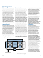
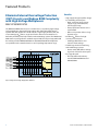
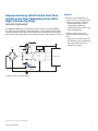
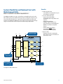
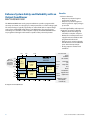
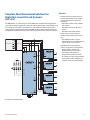
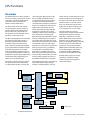
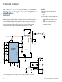
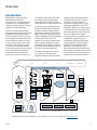
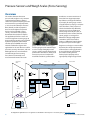
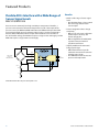
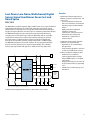
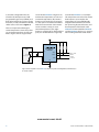
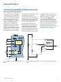
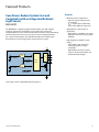
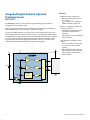
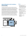
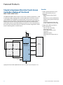
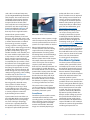
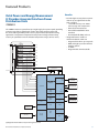
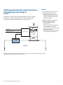
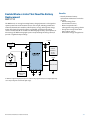
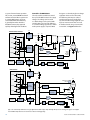
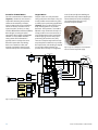
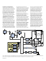
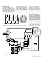
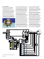
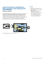
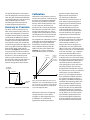
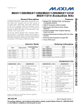
Analog Output Functions
Overview
Analog output signals are required in
situations where a compatible transducer
or instrument needs to be driven.
Common examples include proportional
valves and current-loop-controlled
actuators. It can be part of a simple
open-loop control system or part of a
complex control loop in a proportionalintegral-derivative (PID) system where
the result of this output is sensed and
fed back to the PLC for PID processing.
The Signal Chain
The analog output begins with digital
data from the microprocessor. This digital
data is converted into an analog voltage
or current signal with a digital-to-analog
converter (DAC). Signal-conditioning
circuitry then provides reconstruction
filtering, offset, gain, muxing, sample/
hold, and drive amplification as needed.
As with the analog inputs, various
implementations of the signal chain are
possible when multiple analog outputs
are needed. Maxim has precision DACs
ranging from below 8 bits up to 16
bits of resolution and from a single
channel up to 32 channels. Calibration
DACs are available from 4 to 16 bits and
our sample/hold amplifiers provide
additional ways to hold many outputs
Long-Range Analog
Communications
at constant voltages while the DAC
services other outputs. Many of our
multichannel DACs allow all outputs
to be updated simultaneously through
the use of cascaded registers. Maxim’s
broad product offering is a distinct
advantage for the PLC designer.
For precise systems, DACs (and ADCs)
require an accurate voltage reference.
The voltage reference may be internal
or external to the data converter. In
addition to many ADCs and DACs
with internal references, Maxim
has stand-alone voltage references
with temperature coefficients as
low as 1ppm/°C, output voltage as
accurate as ±0.02%, and output noise
as low as 1.3µVP-P that can be used
external to the data converter for
ultimate precision and accuracy.
Producing discrete, selectable, voltageoutput (bipolar and unipolar), or
current-output conditioning circuits can
be an involved task. This is especially
true as one begins to understand the
necessity of controlling full-scale gain
variations, the multiple reset levels
for bipolar and unipolar voltages, or
the different output-current levels
that may be needed to provide the
PLC with the most flexible outputs.
The complex impedance of long cables,
EMI, and RFI make voltage-mode
control impractical for many long
distance runs. Coaxial cables ease some
of these problems, but with high cost
per foot. Cable impedance degrades
voltage waveforms, often requiring
preemphasis and signal amplification
before transmission. Furthermore,
in any voltage signaling system, the
danger of sparking is real, especially
when connections are made or broken.
For hazardous environments sparking
must be strictly avoided; instead, a
current-control loop is a simple but
elegant solution. With this approach
wire resistance is removed from the
equation because Kirchhoff’s law tells us
that the current is equal at all points in
the loop. Because the loop impedance
and bandwidth are low (a few hundred
ohms and < 100Hz), EMI and RFI
spurious pickup issues are minimized.
Current-control loops evolved from
early 20th-century teletype impact
printers, first as 0–60mA loops and
later as 0–20mA loops, where signaling
was digital serial with current either
on or off indicating 0 or 1, respectively.
Advances in PLC systems added 4–20mA
ANALOG OUTPUT CONDITIONING CIRCUITRY
DEMUX
PRECISION
RESISTORS
EMI/RFI
FILTERS
SWITCHED
C FILTERS
CALIBRATION
ESD/SIGNAL
PROTECTION
DIGITAL
POTENTIOMETER
HART
MODEM
ANALOG OUTPUT:
V TO V, OR I TO V
FROM CPU
MODULE
DAC
ISOLATION
VOLTAGE/
CURRENT
TO FIELD
WIRING AND
ANALOG
ACTUATORS
DAC
EXCITEMENT, BIAS,
CALIBRATION TO
FIELD WIRING AND
INPUT SENSORS
VOLTAGE
REFERENCE
VOLTAGE
MONITORS
TO ALL
HOT-SWAP
CONTROLLER
POWER SUPPLY
THERMAL
MANAGEMENT
= MAXIM SOLUTION
Maxim’s product offerings are found throughout this block diagram of PLC analog output functions.
12
Control and Automation Solutions Guide