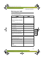
1
3100 Hand.bk Page i Monday, August 19, 2002 8:49 PM TECHNICIAN’S HANDBOOK 3100 Hand.bk Page ii Monday, August 19, 2002 8:49 PM NOTICE The information contained in this document is believed to be accurate in all respects but is not warranted by Mitel Networks Corporation (MITEL®). The information is subject to change without notice and should not be construed in any way as a commitment by Mitel or any of its affiliates or subsidiaries. Mitel and its affiliates and subsidiaries assume no responsibility for any errors or omissions in this document. Revisions of this document or new editions of it may be issued to incorporate such changes. No part of this document can be reproduced or transmitted in any form or by any means - electronic or mechanical - for any purpose without written permission from Mitel Networks Corporation. Mitel Networks is a trademark of Mitel Networks Corporation. Windows is a trademark of Microsoft Corporation. SonicWALL is a trademark of SonicWall, Inc. Other product names mentioned in this document may be trademarks of their respective companies and are hereby acknowledged. Mitel Networks 3100 Integrated Communications Platform Technician’s Handbook Release 3 50002911, Revision B August 2002 , Trademark of MITEL Networks Corporation ©Copyright 2002, MITEL Networks Corporation All rights reserved 3100 Hand.bk Page iii Monday, August 19, 2002 8:49 PM Table of Contents Chapter 1 : Introduction About this handbook . . . . . . . . . . . . . . . . . . . . . . . . . . . . . . . . . . 3 Purpose of this handbook . . . . . . . . . . . . . . . . . . . . . . . . . . . . . . . . 3 Who this handbook is written for . . . . . . . . . . . . . . . . . . . . . . . . . . . 3 Where you can find more information . . . . . . . . . . . . . . . . . . . . . . . 3 Symbols used in this handbook . . . . . . . . . . . . . . . . . . . . . . . . . . . 5 Important safety instructions . . . . . . . . . . . . . . . . . . . . . . . . . . . . . . 6 About the 3100 ICP system . . . . . . . . . . . . . . . . . . . . . . . . . . . . . 7 Description . . . . . . . . . . . . . . . . . . . . . . . . . . . . . . . . . . . . . . . . . . . 7 Basic system configuration . . . . . . . . . . . . . . . . . . . . . . . . . . . . . . . 7 A fully expanded system . . . . . . . . . . . . . . . . . . . . . . . . . . . . . . . . . 8 Voice functionality . . . . . . . . . . . . . . . . . . . . . . . . . . . . . . . . . . . . . . 8 Data functionality. . . . . . . . . . . . . . . . . . . . . . . . . . . . . . . . . . . . . . . 8 What telephone features are supported? . . . . . . . . . . . . . . . . . . . . 9 Chapter 2 : Installation Before you begin. . . . . . . . . . . . . . . . . . . . . . . . . . . . . . . . . . . . . 19 Hardware ports and connectors . . . . . . . . . . . . . . . . . . . . . . . . . . 19 Controller components . . . . . . . . . . . . . . . . . . . . . . . . . . . . . . . . . 20 Identify the required components . . . . . . . . . . . . . . . . . . . . . . . . . 21 Installation checklist . . . . . . . . . . . . . . . . . . . . . . . . . . . . . . . . . . . 22 Installation overview. . . . . . . . . . . . . . . . . . . . . . . . . . . . . . . . . . 24 Installing the system components . . . . . . . . . . . . . . . . . . . . . . 25 Configuring the PC . . . . . . . . . . . . . . . . . . . . . . . . . . . . . . . . . . . 26 Windows 95/98 . . . . . . . . . . . . . . . . . . . . . . . . . . . . . . . . . . . . . . . 26 Windows NT . . . . . . . . . . . . . . . . . . . . . . . . . . . . . . . . . . . . . . . . . 26 Windows 2000. . . . . . . . . . . . . . . . . . . . . . . . . . . . . . . . . . . . . . . . 27 Windows ME . . . . . . . . . . . . . . . . . . . . . . . . . . . . . . . . . . . . . . . . . 27 Windows XP . . . . . . . . . . . . . . . . . . . . . . . . . . . . . . . . . . . . . . . . . 28 Launching the tools . . . . . . . . . . . . . . . . . . . . . . . . . . . . . . . . . . 29 Running the quick installation tool . . . . . . . . . . . . . . . . . . . . . . 30 About the system quick installation tool . . . . . . . . . . . . . . . . . . . . 30 Key system, PBX, or other? . . . . . . . . . . . . . . . . . . . . . . . . . . . . . 30 Using the system quick installation tool . . . . . . . . . . . . . . . . . . . . 31 Connect the phones and lines . . . . . . . . . . . . . . . . . . . . . . . . . . 34 Verify the system . . . . . . . . . . . . . . . . . . . . . . . . . . . . . . . . . . . . 35 Installation tips . . . . . . . . . . . . . . . . . . . . . . . . . . . . . . . . . . . . . . 36 iii 3100 Hand.bk Page iv Monday, August 19, 2002 8:49 PM Technician’s Handbook Chapter 3 : Programming Programming overview . . . . . . . . . . . . . . . . . . . . . . . . . . . . . . . About the programming tools . . . . . . . . . . . . . . . . . . . . . . . . . . Tools are password protected . . . . . . . . . . . . . . . . . . . . . . . . . Enable your options . . . . . . . . . . . . . . . . . . . . . . . . . . . . . . . . . . Programming the system parameters . . . . . . . . . . . . . . . . . . . Set system date and time. . . . . . . . . . . . . . . . . . . . . . . . . . . . . . . Review the numbering plan . . . . . . . . . . . . . . . . . . . . . . . . . . . . . Set the login attributes for users. . . . . . . . . . . . . . . . . . . . . . . . . . Changing the system-wide settings . . . . . . . . . . . . . . . . . . . . . . . Identify the power source of the IP phones . . . . . . . . . . . . . . . . . Program the online services . . . . . . . . . . . . . . . . . . . . . . . . . . . . . Programming the extensions . . . . . . . . . . . . . . . . . . . . . . . . . . Program the extensions . . . . . . . . . . . . . . . . . . . . . . . . . . . . . . . . Program the extension groups . . . . . . . . . . . . . . . . . . . . . . . . . . . Program the extension voice mailboxes. . . . . . . . . . . . . . . . . . . . Program the extension personal keys . . . . . . . . . . . . . . . . . . . . . Programming the voice parameters . . . . . . . . . . . . . . . . . . . . . Modify the extensions and system directory. . . . . . . . . . . . . . . . . Program the incoming access (ring maps) . . . . . . . . . . . . . . . . . . Program external access (line and hunt groups) . . . . . . . . . . . . . Programming BRI ISDN access (UK only) . . . . . . . . . . . . . . . . . . Restrict external access (toll restriction/call barring) . . . . . . . . . . Program the voice management parameters . . . . . . . . . . . . . . . . Programming the voice mail settings. . . . . . . . . . . . . . . . . . . . Setting up the auto attendant . . . . . . . . . . . . . . . . . . . . . . . . . . Log in to the administrator station . . . . . . . . . . . . . . . . . . . . . . . . Record the system greetings . . . . . . . . . . . . . . . . . . . . . . . . . . . . Record the bilingual welcome greeting. . . . . . . . . . . . . . . . . . . . . Configuring call logging (SMDR) . . . . . . . . . . . . . . . . . . . . . . . Commit your changes . . . . . . . . . . . . . . . . . . . . . . . . . . . . . . . . Perform a database backup. . . . . . . . . . . . . . . . . . . . . . . . . . . . Programming tips. . . . . . . . . . . . . . . . . . . . . . . . . . . . . . . . . . . . 39 40 41 41 42 42 42 43 45 45 46 47 47 47 48 48 50 50 51 52 53 58 60 61 62 62 63 64 65 67 67 68 Chapter 4 : Configuring the IP network About IP networking. . . . . . . . . . . . . . . . . . . . . . . . . . . . . . . . . . 71 Network capabilities. . . . . . . . . . . . . . . . . . . . . . . . . . . . . . . . . . 72 iv 3100 Hand.bk Page v Monday, August 19, 2002 8:49 PM Table of Contents Planning your LAN . . . . . . . . . . . . . . . . . . . . . . . . . . . . . . . . . . . 73 Default controller IP addresses . . . . . . . . . . . . . . . . . . . . . . . . . . . 74 IP programming sequence . . . . . . . . . . . . . . . . . . . . . . . . . . . . . 75 Connecting directly to the Internet . . . . . . . . . . . . . . . . . . . . . . 76 Using Static IP addressing . . . . . . . . . . . . . . . . . . . . . . . . . . . . . . 78 Using DHCP Client . . . . . . . . . . . . . . . . . . . . . . . . . . . . . . . . . . . . 78 Using Broadband Access (PPPoE). . . . . . . . . . . . . . . . . . . . . . . . 79 Commit your changes . . . . . . . . . . . . . . . . . . . . . . . . . . . . . . . . . . 80 Connecting to the Internet through an existing LAN . . . . . . . . . . . . . . . . . . . . . . . . . . . . . . . . . . . . . . 81 Through the WAN port . . . . . . . . . . . . . . . . . . . . . . . . . . . . . . . . . 81 Through a layer-2 switch port (custom configuration) . . . . . . . . . . 83 Using a remote DHCP server . . . . . . . . . . . . . . . . . . . . . . . . . . . 85 What you need . . . . . . . . . . . . . . . . . . . . . . . . . . . . . . . . . . . . . . . 85 Configuring the 3100 ICP . . . . . . . . . . . . . . . . . . . . . . . . . . . . . . . 85 Configuring the external DHCP server . . . . . . . . . . . . . . . . . . . . . 86 Changing the assigned DHCP IP address range . . . . . . . . . . . 88 Configuring Domain Name Service . . . . . . . . . . . . . . . . . . . . . . 91 Assigning a gateway. . . . . . . . . . . . . . . . . . . . . . . . . . . . . . . . . . 93 Programming dial-up access to an ISP. . . . . . . . . . . . . . . . . . . 95 Restricting LAN access (firewall) . . . . . . . . . . . . . . . . . . . . . . . 97 Connecting the 6000 SBAP to the layer-2 switch port . . . . . . . . . 97 Connecting the 6000 SBAP to the WAN port . . . . . . . . . . . . . . . 100 SonicWALL SOHO2 . . . . . . . . . . . . . . . . . . . . . . . . . . . . . . . . . . 102 IP networking tips . . . . . . . . . . . . . . . . . . . . . . . . . . . . . . . . . . . 106 Chapter 5 : Routine maintenance Is the system healthy? . . . . . . . . . . . . . . . . . . . . . . . . . . . . . . . 109 System health checklist. . . . . . . . . . . . . . . . . . . . . . . . . . . . . . . . 109 Is the system secure?. . . . . . . . . . . . . . . . . . . . . . . . . . . . . . . . 110 Checking the system . . . . . . . . . . . . . . . . . . . . . . . . . . . . . . . . 111 Launching the tools . . . . . . . . . . . . . . . . . . . . . . . . . . . . . . . . . 113 Enabling your licensed options. . . . . . . . . . . . . . . . . . . . . . . . 114 Obtain your MOSS option code . . . . . . . . . . . . . . . . . . . . . . . . . 114 Rebooting the system. . . . . . . . . . . . . . . . . . . . . . . . . . . . . . . . 116 Powering down the system . . . . . . . . . . . . . . . . . . . . . . . . . . . 117 Powering up the system. . . . . . . . . . . . . . . . . . . . . . . . . . . . . . 118 v 3100 Hand.bk Page vi Monday, August 19, 2002 8:49 PM Technician’s Handbook Upgrading the system . . . . . . . . . . . . . . . . . . . . . . . . . . . . . . . Installing option modules . . . . . . . . . . . . . . . . . . . . . . . . . . . . . . Adding an expansion unit . . . . . . . . . . . . . . . . . . . . . . . . . . . . . . Performing a software upgrade . . . . . . . . . . . . . . . . . . . . . . . . . Applying a software patch . . . . . . . . . . . . . . . . . . . . . . . . . . . . . Replacing a flash card . . . . . . . . . . . . . . . . . . . . . . . . . . . . . . . . Performing backups. . . . . . . . . . . . . . . . . . . . . . . . . . . . . . . . . Creating backup directories . . . . . . . . . . . . . . . . . . . . . . . . . . . . Backing up the software and/or database . . . . . . . . . . . . . . . . . Backing up the voice mail data. . . . . . . . . . . . . . . . . . . . . . . . . . Saving call (SMDR) logs . . . . . . . . . . . . . . . . . . . . . . . . . . . . . Using a remote access session . . . . . . . . . . . . . . . . . . . . . . . Setting up remote access. . . . . . . . . . . . . . . . . . . . . . . . . . . . . . Launching the tools from a remote session . . . . . . . . . . . . . . . . Changing extensions or set types . . . . . . . . . . . . . . . . . . . . . Changing an extension number or set type . . . . . . . . . . . . . . . . Reset the phone . . . . . . . . . . . . . . . . . . . . . . . . . . . . . . . . . . . . . Creating a user guide. . . . . . . . . . . . . . . . . . . . . . . . . . . . . . . . Using a database template . . . . . . . . . . . . . . . . . . . . . . . . . . . Maintenance tips . . . . . . . . . . . . . . . . . . . . . . . . . . . . . . . . . . . 119 119 120 121 123 123 128 128 128 129 130 131 131 133 135 135 135 136 137 138 Chapter 6 : Troubleshooting and repair Checking the system LEDs . . . . . . . . . . . . . . . . . . . . . . . . . . . Checking the logs . . . . . . . . . . . . . . . . . . . . . . . . . . . . . . . . . . Viewing diagnostics . . . . . . . . . . . . . . . . . . . . . . . . . . . . . . . . . Starting a diagnostic session . . . . . . . . . . . . . . . . . . . . . . . . . . . Checking the bootup script . . . . . . . . . . . . . . . . . . . . . . . . . . . . . Line troubleshooting . . . . . . . . . . . . . . . . . . . . . . . . . . . . . . . . IP phone troubleshooting . . . . . . . . . . . . . . . . . . . . . . . . . . . . Analog phone troubleshooting . . . . . . . . . . . . . . . . . . . . . . . . System troubleshooting . . . . . . . . . . . . . . . . . . . . . . . . . . . . . Network troubleshooting . . . . . . . . . . . . . . . . . . . . . . . . . . . . . Using Windows networking commands. . . . . . . . . . . . . . . . . Using VxWorks networking commands . . . . . . . . . . . . . . . . . Fixing database or software corruption . . . . . . . . . . . . . . . . . Restoring the database/software and database . . . . . . . . . . . . . Restoring the system with previous software . . . . . . . . . . . . . . . vi 141 142 143 143 144 145 146 147 148 149 150 152 153 154 155 3100 Hand.bk Page vii Monday, August 19, 2002 8:49 PM Table of Contents Restoring the system with the factory software. . . . . . . . . . . . . . 156 Restoring voice mail data . . . . . . . . . . . . . . . . . . . . . . . . . . . . . . 157 Replacing faulty components . . . . . . . . . . . . . . . . . . . . . . . . . 158 Replacing the flash card . . . . . . . . . . . . . . . . . . . . . . . . . . . . . . . 158 Replacing a faulty hard disk . . . . . . . . . . . . . . . . . . . . . . . . . . . . 160 Field replaceable units . . . . . . . . . . . . . . . . . . . . . . . . . . . . . . . 162 Troubleshooting tips . . . . . . . . . . . . . . . . . . . . . . . . . . . . . . . . 163 Appendix A : Default database Default Database . . . . . . . . . . . . . . . . . . . . . . . . . . . . . . . . . . . . 167 Numbering plan. . . . . . . . . . . . . . . . . . . . . . . . . . . . . . . . . . . . . . 168 Numbering assignment . . . . . . . . . . . . . . . . . . . . . . . . . . . . . . . . 168 Analog set configuration . . . . . . . . . . . . . . . . . . . . . . . . . . . . . . . 169 Analog line configuration (NA) . . . . . . . . . . . . . . . . . . . . . . . . . . 169 Restriction groups (extensions). . . . . . . . . . . . . . . . . . . . . . . . . . 169 Timers . . . . . . . . . . . . . . . . . . . . . . . . . . . . . . . . . . . . . . . . . . . . . 170 Feature access codes . . . . . . . . . . . . . . . . . . . . . . . . . . . . . . . . . 172 Appendix B : Reference Call logging (SMDR) details . . . . . . . . . . . . . . . . . . . . . . . . . . . 177 Ring Map handling . . . . . . . . . . . . . . . . . . . . . . . . . . . . . . . . . . 179 Controller card connectors . . . . . . . . . . . . . . . . . . . . . . . . . . . 189 Port pinouts . . . . . . . . . . . . . . . . . . . . . . . . . . . . . . . . . . . . . . . . 190 Line protocols . . . . . . . . . . . . . . . . . . . . . . . . . . . . . . . . . . . . . . 194 Cable pinouts . . . . . . . . . . . . . . . . . . . . . . . . . . . . . . . . . . . . . . 195 Appendix C : Planning Introduction . . . . . . . . . . . . . . . . . . . . . . . . . . . . . . . . . . . . . . . . 199 System parameters . . . . . . . . . . . . . . . . . . . . . . . . . . . . . . . . . . 200 Voice parameters . . . . . . . . . . . . . . . . . . . . . . . . . . . . . . . . . . . 201 Toll restriction . . . . . . . . . . . . . . . . . . . . . . . . . . . . . . . . . . . . . . 208 Voice mail . . . . . . . . . . . . . . . . . . . . . . . . . . . . . . . . . . . . . . . . . 209 IP networking. . . . . . . . . . . . . . . . . . . . . . . . . . . . . . . . . . . . . . . 210 Index vii 3100 Hand.bk Page viii Monday, August 19, 2002 8:49 PM Technician’s Handbook viii 3100 Hand.bk Page 1 Monday, August 19, 2002 8:49 PM Chapter 1 Introduction 3100 Hand.bk Page 2 Monday, August 19, 2002 8:49 PM Technician’s Handbook 2 3100 Hand.bk Page 3 Monday, August 19, 2002 8:49 PM Introduction Introduction About this handbook Purpose of this handbook This handbook provides • an overview of the system capabilities • installation steps • programming procedures • maintenance checklists • troubleshooting information Who this handbook is written for This handbook is for a certified technician. Where you can find more information Technical manual and extension guides On the system software CD-ROM 1. Insert the system software CD-ROM in the CD-ROM drive of your PC. 2. If the CD-ROM does not start automatically, open Windows® Explorer and navigate to the CD-ROM directory. Click Autorun.exe. 3. In the Welcome screen, click Online Help at the top of the list. From the tools 1. After initial installation, launch your browser and go to the following URL: http://192.168.1.2 2. Click Help. 3 3100 Hand.bk Page 4 Monday, August 19, 2002 8:49 PM Technician’s Handbook From the internet 1. Go to the following URL: http://www.mitel.com 2. Access Mitel OnLine from the Online Services selection menu. 3. Click Technical Support and then click Customer Documentation (edocs). User Guides through Manual Maker Manual Maker is a web-base application that allows you to generate customized user guides 1. Go to the following URL: http://www.mitel.com 2. Access Mitel OnLine from the Online Services selection menu. 3. Click Technical Support and then click Manual Maker. You can also launch Manual Maker from the group administration tool. Field change instructions Every software release is accompanied by a Field Change Instruction (FCI). The FCI describes software changes, bug fixes, outstanding issues, and hardware compatibility considerations for the new software release. Read the FCI before you begin a software upgrade. The FCI is included on the system software CD-ROM. You can also obtain the latest FCI from Mitel OnLine at www.mitel.com. Note that you must be a registered user to access Mitel OnLine. Technical Service/Information Bulletins Technical Service Bulletins (TSBs) and Technical Information Bulletins (TIBs) are issued by Mitel Technical 4 Introduction Helpful websites For definitions of technical terms • http://www.techweb.com/encyclopedia • http://www.whatis.com For networking information • http://www.practicallynetworked.com • http://www.networktroubleshooting.com Terminology Glossaries are provided in the Technical Manual and in the Installation and Maintenance Course Student Manual. Symbols used in this handbook A stop symbol indicates a hazardous situation which, if not avoided, could result in injury or death. A yield symbol with an exclamation mark indicates a situation which, if not avoided, could result in damage to the equipment. A light bulb identifies an important note or a useful tip. %]Y^ A clock indicates the amount of time that is required to perform the associated step. A pointer symbol identifies an important cross reference. 5 Introduction Support to address frequently asked questions regarding software and hardware problems. Obtain the latest TSBs from Mitel OnLine. 3100 Hand.bk Page 6 Monday, August 19, 2002 8:49 PM Technician’s Handbook Important safety instructions Failure to follow all instructions may result in improper equipment operation and/or risk of electrical shock. See the Safety Instructions in the 3100 ICP Technical Manual for complete safety information. Safety Instructions are also provided with the system in paper format. 6 3100 Hand.bk Page 7 Monday, August 19, 2002 8:49 PM Introduction Introduction About the 3100 ICP system Description The Mitel Networks™ 3100 Integrated Communications Platform (ICP) provides a complete voice and data solution in one easy-to-manage unit. The 3100 ICP controller contains the call control software, a router, a layer-2 switch, embedded voice mail with an auto attendant, and a hard-drive for storing voice mail messages and the management tool web pages. Figure 1: 3100 ICP controller, option modules, and expansion unit Basic system configuration The basic system supports • 8 Mitel Networks IP (Internet Protocol) Phones • 2 ONS (on premise station) analog telephones • 1 wide area network (WAN) Ethernet port for connections to WAN services such as cable or Digital Subscriber Line (DSL) • 4 LS/CLASS interfaces • 100 IP devices. 7 3100 Hand.bk Page 8 Monday, August 19, 2002 8:49 PM Technician’s Handbook A fully expanded system A fully expanded system consists of the controller, fitted with three optional modules, and the expansion unit. It provides • up to 24 Mitel Networks IP (Internet Protocol) phones • up to 10 analog telephones with Calling Line Identification (CLI) capability • up to 8 LS/CLASS lines or 8 ISDN BRI lines (UK only) The system supports a maximum of 8 lines. In the UK, these can be a combination of LS/CLASS lines and ISDN BRI lines. • 1 Wide Area Network (WAN) Ethernet port for connections to WAN services such as cable or DSL • 100 IP devices. The system supports a maximum of two ONS interface modules and one LS/CLASS module. Voice functionality • Full set of voice features • Key System, PBX, or customized system • Fully featured voice mail and auto attendant. Data functionality 8 • Integrated 10/100 Mbs layer-2 switch • Dynamic Host Configuration Protocol (DHCP) server that supports up to 100 IP addresses • IP Routing / WAN router, Domain Naming System (DNS) and Network Address Translation (NAT) 3100 Hand.bk Page 9 Monday, August 19, 2002 8:49 PM Introduction Remote WAN locations supported through Ethernet WAN interface or dial-up Point-to-Point Protocol (PPP) connections. • Built-in modem • IP set powering. What telephone features are supported? Note that the Mitel Networks 5001 and 5005 IP phones are not available in Release 2.3 or earlier. Table 1: Functions and features available on sets 5TPcdaTb $ $$ $ $! $'!! $ # Number of fixed function/application/telephony keys 3 2 6 8 8 13 Number of personal/quick keys -- 20 7 14 14 9 Number of pre-assigned personal/quick keys -- 3 1 1 1 1 Dual or single-colored personal keys -- single dual dual dual -- Number of soft command keys -- -- -- 3 3 6 Number of system speed call numbers (short codes) available 1000 system-wide LCD display N 1 line 2 line 2 line 2 line 320x 240 VGA Headset operation N N Y Y Y Y Message waiting indicator Y Y Y Y Y Y Account codes - allocate to incoming or outgoing calls Y Y Y Y Y Y Adjust display contrast N Y Y Y Y Y Adjust handset receiver volume Y Y Y Y Y Y 9 Introduction • 3100 Hand.bk Page 10 Monday, August 19, 2002 8:49 PM Technician’s Handbook Table 1: Functions and features available on sets (continued) 5TPcdaTb $ $$ $ $! $'!! $ # Adjust ringer pitch N N Y Y Y Y Adjust volume of the speaker N Y Y Y Y Y Administrator extension N N N Y Y Y Alarm calls - setup for other extension users N N N Admin Admin Admin only only only Alarm calls - setup on own extension Y Y Y Y Y Y Answer external call via personal/quick key N Y Y Y Y Y Answer next call via personal/quick key N Y Y Y Y Y Auto attendant access Y Y Y Y Y Y Automatically answer incoming external calls (auto answer) N N N Y Y Y Automatically answer a call and define the type of response to give N N N N Y N Automatic hold Y Y Y Y Y Y Bookmarks - enables the extension user to access a list of user-defined URLs. N N N N N Y Call status information - LCD provides information about status of extension and current call N Y Y Y Y Y Callback when free Y Y Y Y Y Y Calls For - identifies diverting extenN sion number Y Y Y Y Y Cancel a message waiting request Y Y Y Y Y Y Cancel call forwarding Y Y Y Y Y Y 10 3100 Hand.bk Page 11 Monday, August 19, 2002 8:49 PM Introduction 5TPcdaTb $ $$ $ $! $'!! $ # Conference call - enable an extension user to set-up a call between three parties N Y Y Y Y Y Direct Station Select/Busy Lamp Field (DSS/BLF) keys - setup at extension N Y Y Y Y Y Directed Message Waiting - leave a message for another extension user Y without calling the extension first Y Y Y Y Y Display caller’s number and name N Y Y Y Y Y Do Not Disturb Y Y Y Y Y Y Doorphone operation N Y Y Y Y Y Dual Tone Multi-Frequency Tone Dialing Y Y Y Y Y Y Exclusive Hold - place a call on hold which can only be retrieved by the N extension that placed the call on hold Y Y Y Y Y Extension Groups - extension can be associated with a group Y Y Y Y Y Y Extension Paging - broadcast a message to a single, group or all extensions on the system N Y Y Y Y Y Extension Status Announcement Y Y Y Y Y N Extension-to-extension dialing user can dial another extension directly Y Y Y Y Y Y External Call Waiting - indicates that an external call has arrived when an Y extension user is busy on another call Y Y Y Y Y 11 Introduction Table 1: Functions and features available on sets (continued) 3100 Hand.bk Page 12 Monday, August 19, 2002 8:49 PM Technician’s Handbook Table 1: Functions and features available on sets (continued) 5TPcdaTb $ $$ $ $! $'!! $ # Follow Me - enables calls to follow an extension user to another exten- Y sion within the office Y Y Y Y Y Follow Me (I’m Here) - enables an extension user to direct calls from Y their usual extension to their current extension Y Y Y Y Y Forward/Divert all incoming calls to another extension or extension group Y Y Y Y Y Y Forward/Divert calls to an external destination Y Y Y Y Y Y Forward/Divert incoming calls to another extension or extension group if extension is busy Y Y Y Y Y Y Group Listen - enables others nearby to listen to a call while allowN ing only the extension user to speak to the other party Y Y Y Y Y Handsfree operation (full) - enables extension users to make and answer calls, and listen and respond to broadcast messages without lifting the handset N N N Y Y Y Handsfree operation (partial) enables extension users to make calls and listen to broadcast messages without lifting handset N Y Y Y Y Y Hotline Y Y Y Y Y Y Identify Next Call Announcement Y Y Y Y Y Y Intrude into an established call N Y Y Y Y Y Last Call Duration Announcement Y Y Y Y Y N Last Call Duration Display N Y Y Y Y Y 12 3100 Hand.bk Page 13 Monday, August 19, 2002 8:49 PM Introduction 5TPcdaTb $ $$ $ $! $'!! $ # Last Number Redial Y Y Y Y Y Y List of Calls - display the 10 most recent, different external calls to an extension N N Y Y Y Y Message Waiting - leave indicator for another extension user Y Y Y Y Y Y Messaging - enables an extension user to display a message at the calling extension, for example, GONE TO LUNCH N Y Y Y Y Y Monitor a call between two external parties N N N Admin Admin Admin only only only Night Service - place a call in night service mode 1 or 2 N N N Admin Admin Admin only only only Online Services - enables the extension user to access a list of URLs programmed by the administrator. N N N N N Y Page via the loudspeaker system Y Y Y Y Y Y Park an external call for another extension user to retrieve N Y Y Y Y Y Personal Digital Assistant (PDA) support N N N Y1 N Y Personal Directory - create entries specific to extension N N N Y Y Y Personal speed calls - store under personal, quick keys, or keypad keys Y Y Y Y Y Y Phonebook N N N Y Y Y Pick up a call ringing at a colleague’s extension Y Y Y Y Y Y 13 Introduction Table 1: Functions and features available on sets (continued) 3100 Hand.bk Page 14 Monday, August 19, 2002 8:49 PM Technician’s Handbook Table 1: Functions and features available on sets (continued) 5TPcdaTb $ $$ $ $! $'!! $ # Pick up a call ringing at another extension in the user’s extension group Y Y Y Y Y Y Pick up an incoming call when the system is in Night Service mode 1 or 2 Y Y Y Y Y Y Pick up a parked call Y Y Y Y Y Y PIN Codes - prevent unauthorised users from making external calls from an extension Y Y Y Y Y Y Prime Line N Y Y Y Y Y Recall on lines N Y Y Y Y Y Redial List - enables an extension user to save and prioritize ten exter- N nally-dialled numbers Y Y Y Y Y Re-establish a reverted call attempts to re-connect the reverted call N Y Y Y Y Y Ringer On/Off - enables an extension user to turn off the ringer for all incoming calls that arrive under a personal/quick key N Y Y Y Y Y Selective Ringer - enables an extension user to selectively turn off N the ringer for calls that arrive under specific personal/quick key(s) Y Y Y Y Y Store a call under a personal/quick key N Y Y Y Y Y Swap (Broker’s Call) N Y Y Y Y Y System Directory - enables extension users to dial from directory setup by the Administrator N N N Y Y Y 14 3100 Hand.bk Page 15 Monday, August 19, 2002 8:49 PM Introduction 5TPcdaTb $ $$ $ $! $'!! $ # System Hold - place a call on hold which can be retrieved by any extension on the system N Y Y Y Y Y Time and date announcement Y Y Y Y Y N Time and date change N N N Admin Admin Admin only only only Transfer a call N Y Y Y Y Y Visual Voice Mail (VVM) - allows the extension user to visually interact with their voice mailbox. N N N N N Y Who Am I? - indicates the extension Y number Y Y Y Y Y 1. If a Mitel Networks 5423 IRDA Module is attached. 15 Introduction Table 1: Functions and features available on sets (continued) 3100 Hand.bk Page 16 Monday, August 19, 2002 8:49 PM Technician’s Handbook 16 3100 Hand.bk Page 17 Monday, August 19, 2002 8:49 PM Chapter 2 Installation 3100 Hand.bk Page 18 Monday, August 19, 2002 8:49 PM Technician’s Handbook 18 3100 Hand.bk Page 19 Monday, August 19, 2002 8:49 PM Installation Before you begin Hardware ports and connectors Installation Figure 2: Controller front panel Figure 3: Controller rear panel 19 3100 Hand.bk Page 20 Monday, August 19, 2002 8:49 PM Technician’s Handbook Figure 4: Expansion unit front panel Controller components Figure 5: Controller components 20 3100 Hand.bk Page 21 Monday, August 19, 2002 8:49 PM Installation Identify the required components The system size is determined by the type and number of components. Table 2: System components Controller (basic configuration) 2P_PQX[XcXTb Installation BhbcT\R^\_^]T]cb 8 Mitel Networks IP Phones 2 ONS analog telephones 1 wide area network Ethernet or xDSL interface 4 LS/CLASS interfaces 100 IP devices. Plus up to three of the following modules (maximum of one LS/CLASS module; two BRI modules) 4-circuit ONS module Provides connection for four analog phones LS/CLASS module Provides connections to four LS/CLASS circuits BRI module (UK only) Provides two 2B+D SIT interfaces Analog service module Provides overhead paging capability Plus one of the following 8-port expansion unit Provides an additional 8 layer-2 switch ports for the connection of LAN devices (IP phones and PCs) 16-port expansion unit Provides an additional 16 layer-2 switch ports Up to eight lines are supported. In the UK, the eight lines can be a combination of LS/CLASS lines and ISDN BRI lines. See A fully expanded system (p. 8) for system maximums. Refer to the technical manual for examples of system configurations. 21 3100 Hand.bk Page 22 Monday, August 19, 2002 8:49 PM Technician’s Handbook Installation checklist Tools ã Static strap ã Phillips screwdriver Cables and connectors ã Category 5 (CAT5) cable for all LAN devices (IP phones, computers, servers and so forth) ã CAT3 or CAT5 cable for analog phones connected to the system ã RJ-45 cable and connectors ã RJ-45 crossover (patch) cable. See Cable pinouts (p. 195) ã RS-232 cable for printer. PC requirements ã Windows 95/NT/98/2000/ME/XP PC or laptop ã Internet Explorer 5.5 with Service Pack 2 or later, and 128 bit encryption ã Administrator login privileges for Windows operating system. Trunk requirements ã LS/CLASS or ISDN BRI (UK only) trunks. 22 3100 Hand.bk Page 23 Monday, August 19, 2002 8:49 PM Installation LAN requirements ã Pre-installation questionnaire complete ã Internet Service Provider (ISP) ã Refer to Planning your LAN (p. 73) for additional requirements. ã @_gUbRQbgYdXcebWU`b_dUSdY_^ ã Music on hold source (radio, tape player, or .wav file) ã Call logging printer, call accounting package, or call management application. 23 Installation Other 3100 Hand.bk Page 24 Monday, August 19, 2002 8:49 PM Technician’s Handbook Installation overview 24 ã Install system components ã Configure the PC ã Power up the system ã Launch the tools ã Run the quick install tool ã Connect the phones and lines ã Verify the system ã Program the system. 3100 Hand.bk Page 25 Monday, August 19, 2002 8:49 PM Installation Installing the system components The 3100 ICP system is shipped with the system software installed and includes a default database. Option modules are shipped uninstalled. 2. If your system includes an expansion unit, install the uplink card in the controller. See Adding an expansion unit (p. 120). 3. Wall mount the units, rack mount them, or place them on a desk or shelf. Instructions are provided on the installation sheets that are included with the units. 9Vi_eQbUgQ\\]_e^dY^WQe^Yd`_cYdY_^YdgYdXdXUVb_^d `Q^U\VQSY^Wd__^UcYTUc_dXQddXU`_bdcQ^T S_^^USd_bcQbUQSSUccYR\U 4. Connect the controller to the expansion unit with the uplink cable and Y-power cord (see Figure 17). 5. Connect the ground stud on the rear panel of the controller to a hard-wired ground using 18 AWG (0.75mm 2/) gauge wire. The wire must have green or yellow insulation. Crimp the wire to the ground source. 6. Connect a PC to the layer-2 switch port on the controller. Do not connect the sets to the controller at this time. 7. Power up the system. See Powering up the system (p. 118). 25 Installation 1. If your system includes option modules, install them in the controller. See Installing option modules (p. 119). 3100 Hand.bk Page 26 Monday, August 19, 2002 8:49 PM Technician’s Handbook Configuring the PC Configure your PC to connect to the 3100 ICP system. Windows 95/98 1. From the Start menu, click Settings and then click Control Panel. 2. In the Control Panel window, double click the Network icon. 3. Click Configuration. 4. Click the TCP/IP component and then click Properties. 5. Select “Obtain an IP address automatically”. 6. Click OK. 7. Restart your PC. You are now set up to connect to the 3100 ICP system. Windows NT 1. Login to the PC with administrator privileges. 2. In the Control Panel window, double click the Network icon. 3. Click Protocols. 4. Click TCP/IP Protocols and then click Properties. 5. From the Adapter drop down list, highlight the device that is being used to connect to the 3100 ICP system, then click Obtain an IP address from a DHCP server. 6. Click OK. 26 3100 Hand.bk Page 27 Monday, August 19, 2002 8:49 PM Installation 7. Click Yes and then restart your PC. You are now set up to connect to the 3100 ICP system. Windows 2000 1. Login to the PC with administrator privileges. 3. In the Control Panel window, double click the Network and Dial Up Connections icon. Double click on the Local Area Connection. In the Local Area Connection Status Page, click Properties. 4. Click Obtain an IP address automatically. 5. From the Adapter drop down list, highlight the device that is being used to connect to the 3100 ICP system, then click Obtain an IP address from a DHCP server. 6. Click OK. You are now set up to connect to the 3100 ICP system. Windows ME 1. From the Start menu, select the Settings tab and then Control Panel. 2. In the Control Panel window, double click the Network icon. 3. Select the Configuration tab in the Network window. This window displays a list of installed network components. Highlight the TCP/IP component and click Properties. 4. Select the radio button marked Obtain an IP address automatically. 5. Click OK then restart your PC. You are now set up to connect to the 3100 ICP system. 27 Installation 2. In the Control Panel window, double click the Network icon. 3100 Hand.bk Page 28 Monday, August 19, 2002 8:49 PM Technician’s Handbook Windows XP 1. Login to the PC with administrator privileges. 2. From the Start menu, select the Settings tab and then Control Panel. 3. In the Control Panel window, double click the Network and Internet Connection icon. Double click on the Local Area Connection (LAN or High Speed Internet). 4. Click General in the Local Area Connection Status page and choose Properties. 5. Click General tab in the Local Area Connection Properties window. This displays a list of installed components. Highlight Internet Protocol (TCP/IP) and choose Properties. 6. Select Obtain an IP address automatically. 7. Click OK. You are now set up to connect to the 3100 ICP system. 28 3100 Hand.bk Page 29 Monday, August 19, 2002 8:49 PM Installation Launching the tools You can connect a PC or laptop to the 3100 ICP system through a LAN drop • the Ethernet port on the back of the IP Phone • directly to a layer-2 switch port on the Mitel Networks 3100 ICP controller or expansion unit. You must configure the PC to accept an IP address from the 3100 ICP system. See Configuring the PC (p. 26). You can also access the 3100 ICP system remotely by dialing into the Mitel Networks 3100 ICP system through a trunk (using the installed V.90 modem) or through the Internet. See Using a remote access session (p. 131) for more details. To launch a tool 1. Launch your browser and go to the following URL: http://192.168.1.2 2. Enter your username and password Login: system (default) Password: mnet (default) 3. Click – Group Administration Tool – System Tool, or – System Quick Installation Tool 4. Proceed to Programming the voice parameters (p. 50). You can only have one system tool session or one Telnet tool session open at any time. The system quick installation tool is only used during the initial configuration of the system. 29 Installation • 3100 Hand.bk Page 30 Monday, August 19, 2002 8:49 PM Technician’s Handbook Running the quick installation tool About the system quick installation tool Use the system quick installation tool to get the system up and running. All further programming is performed from the group administration tool or system tool. The system quick installation tool automatically discovers the addresses of the IP phones and assigns them extension numbers. After you exit the quick installation tool, auto-discovery is disabled. Any phone that you add later, must be programmed through the system tool. If you install systems frequently, or if you plan to program the system at a dealer site, you should create a database template and apply it when you run the quick install tool. Using a template reduces the amount of programming required. See Using a database template (p. 137). Key system, PBX, or other? When you run the quick configuration tool, you are prompted to select one of the following modes Key System Mode - Incoming calls ring all extensions at the same time PBX Mode - Incoming calls ring one extension Other - Allows you to load a database template into the system. The default is PBX Mode. If you choose to change the mode to Key System or Other, you will have to reboot the system and then restart the quick installation tool. If you change the mode, after you reboot the system, remember to click Next the second time that the configuration tool prompts you to select the mode. 30 3100 Hand.bk Page 31 Monday, August 19, 2002 8:49 PM Installation Using the system quick installation tool Do not close your browser window during the quick installation wizard. If you do not complete the wizard, the system configuration will be invalid. If you accidently close your browser, restart the quick installation tool and enter your information again. 1. Review the system defaults; see (p. 166). 2. Complete the pre-configuration questionnaire that was shipped with the system. 3. If you plan to change the number of digits in the extension numbering plan (for example, from the default 3-digit extension numbers to 4-digit numbers), you should set up the voice mailboxes through the administration mailbox before you run the quick installation tool. D_cUde`dXUf_YSU]QY\R_hUc – Connect an IP phone to a layer-2 switch port on the controller. – Program the mailboxes through the administration set. See Log in to the administrator station (p. 62). 4. Open the Internet Explorer browser on your PC. 5. Enter the following URL: http://192.168.1.2 2__[]Qb[dXU=YdU\#! 93@\_WY^`QWUDXU=YdU\ >Udg_b[c#! 93@\_WY^`QWU_`U^c 31 Installation You should only use the system quick installation tool once during initial installation. 3100 Hand.bk Page 32 Monday, August 19, 2002 8:49 PM Technician’s Handbook 6. In the Mitel Networks 3100 ICP login page, enter Login: system (default) Password: mnet (default) DXU\_WY^^Q]UQ^T`Qccg_bTYcSQcUcU^cYdYfU 7. Click OK. The tools page opens. 32 3100 Hand.bk Page 33 Monday, August 19, 2002 8:49 PM Installation 8. Click System Quick Installation Tool. The initial page opens. Installation 9. Follow the prompts. When you are prompted to set the management tool accounts, ensure that you change the default password. When you are prompted to connect the phones, refer to Connect the phones and lines (p. 34) for additional information. 33 3100 Hand.bk Page 34 Monday, August 19, 2002 8:49 PM Technician’s Handbook Connect the phones and lines When you run the system quick installation script, you will be prompted to connect the IP phones, analog phones and lines to the system. The system will not automatically recognize any IP phone that you connect after the system quick installation tool is finished. 1. Plug the RJ-45 connectors from the IP phones into the layer-2 switch ports on the controller (see Figure 2) and expansion unit (see Figure 4). The first IP phone that you connect to the system is assigned as the administrator station (extension 1000). It’s recommended that you connect a Mitel Networks 5020 IP phone or 5140 IP Appliance into port 1 of the controller. DXUTUVQe\dUhdU^cY_^^e]RUbcV_bdXU9@`X_^UcQbU QccYW^UTY^dXU_bTUbdXQdi_eS_^^USddXU`X_^Uc 2. Plug the RJ-11 connectors from the analog phones into the ONS ports on the ONS modules. 3. Plug the RJ-11 connectors from the LS/CLASS lines into the line ports. 9Vi_e^UUTd_QTTc_]U9@`X_^Uc\QdUbi_eSQ^ bUU^QR\UdXUQed_bUWYcdbQdY_^_`dY_^dXb_eWXdXU CicdU]D__\3X__cUBhbcT\S\YS[BhbcT\fXST bTccX]VbS\YS[2WP]VTQ^TdXU^cUd8?bTc Pdc^aTVXbcaPcX^]T]PQ[TSd_CadT ?^fTaUPX[caP]bUTa)9V`_gUbd_dXUcicdU]VQY\cdXU ?>CcUdS_^^USdUTd_`_bd"UhdU^cY_^!! !Yc Qed_]QdYSQ\\iS_^^USdUTd_\Y^U! 4. If the system supports Basic Rate Interface (UK only), plug the RJ-45 connectors from the Basic Rate Interface (BRI) lines into the BRI modules. 34 3100 Hand.bk Page 35 Monday, August 19, 2002 8:49 PM Installation Verify the system Complete the following procedure to verify that the system is working properly. 1. Dial 675 on each IP phone. The extension number appears in the phone display. Record the extension numbers. The 5140 IP Appliances display their extension number automatically. 2. Verify that you can make calls between the IP phones. 3. Connect an analog phone into the first ONS port on the controller. 4. Verify that you make a call from an IP phone to the analog phone (extension 1100). 5. If your system includes LS/CLASS lines, connect an LS/CLASS line to the first LS/CLASS port on the controller. 6. Place a call into the system and verify that the call rings either the first IP phone (PBX mode) or all IP phones (key system mode). 7. Verify that you can place an external call. Dial 9 to access an external line. 8. If you cannot perform all of the above tasks, check your cable connections. If the problem persists, see Checking the system LEDs (p. 141) 9. Proceed to Programming (p. 37). 35 Installation The system is shipped from the factory with your licensed options enabled. 3100 Hand.bk Page 36 Monday, August 19, 2002 8:49 PM Technician’s Handbook Installation tips 36 • The first IP phone that you connect to the system is assigned as the administrator extension (1000). • The default extension numbers for the IP phones (1000 to 1023) are assigned in the order that you connect the phones, starting with the administrator extension (1000). • The default extension numbers for the analog phones (1100 to 1109) are assigned to ONS ports (1 to 10). • If you do not want the extension numbers to start with the digit 1, you will have to change the numbering plan first. • If you reinstall a Mitel Networks 5822 softphone on a different computer, you must delete its Medium Access Control (MAC) address from system programming before you can reassign it to another computer. • The default IP address of the WAN port is 192.168.0.1. • You can connect loud speaker paging units that support 24 V dc analog connectivity to the system ONS ports. 3100 Hand.bk Page 37 Monday, August 19, 2002 8:49 PM Chapter 3 Programming 3100 Hand.bk Page 38 Monday, August 19, 2002 8:49 PM Technician’s Handbook 38 3100 Hand.bk Page 39 Monday, August 19, 2002 8:49 PM Programming Programming overview This chapter provides the key procedures for programming the system. Refer to the Technical Manual for complete programming information. Before you begin programming, ensure that you have • completed the pre-configuration questionnaire that was shipped with the system • reviewed the default database settings. See (p. 166). The key steps to programming the system are ã 5^QR\Ui_eb`ebSXQcUT_`dY_^c ã @b_WbQ]dXUcicdU]`QbQ]UdUbc ã @b_WbQ]dXUUhdU^cY_^c ã @b_WbQ]dXUf_YSU`QbQ]UdUbc ã @b_WbQ]dXUf_YSU]QY\cUddY^Wc ã Set up the auto attendant ã Configure call logging (SMDR) ã Commit your changes ã Perform backups. 39 Programming If this is a new installation, typically you will run the quick installation tool first. The quick installation tool guides you through basic programming. See Using the system quick installation tool (p. 31). 3100 Hand.bk Page 40 Monday, August 19, 2002 8:49 PM Technician’s Handbook About the programming tools The 3100 ICP system has the following programming tools: System quick installation tool - Use this tool once during initial system installation. Perform all further programming from the other tools. Group administration tool - Use this tool to • set basic system parameters • create the system telephone directory • manage extension and group parameters • set group parameters • add, edit, or delete users from the system directory • configure voice mailboxes • program a user’s personal keys with features • create customized user guides System tool - Use this tool to program the • system-wide parameters • voice parameters (lines, extensions, management, system directory, and voice mail) • IP networking parameters. Desktop Tool - Allows users to • assign features to personal keys • manage personal contact lists • manage internet bookmarks on 5140 IP Appliances. To use the tools, you need a Windows-based computer with Internet Explorer 5.5 with Service Pack 2, or later, and 128 bit encryption. 40 3100 Hand.bk Page 41 Monday, August 19, 2002 8:49 PM Programming Before launching a new tool, you must first exit the current tool and then log in again. If you restart or reboot the system without committing your saved changes to the database first, your changes will be lost. See Commit your changes (p. 67). When using the system tool, always click the Exit button to leave the tool. Tools are password protected Enable your options If this is a new system and you have purchased options, such as bilingual voice mail or additional IP set licenses, you must enable them. See Enabling your licensed options (p. 114). 41 Programming If you enter an incorrect password three times in succession (independent of time or re-starting the system) you will be locked out for 15 minutes. You can disable this lock-out option. See Changing the system-wide settings (p. 45). 3100 Hand.bk Page 42 Monday, August 19, 2002 8:49 PM Technician’s Handbook Programming the system parameters Set system date and time You can change the system date and time through the system quick installation tool, the administration tool, the administrator extension, or through the system tool. The system tool, however, allows you to set the time using either a 12-hour or 24-hour clock. 1. Launch the system tool. See Launching the tools (p. 113). 2. Choose System, from the Selection menu. 3. Click Date and Time and then click Change. 4. Enter the date in the format dd/mm/yyyy. 5. Enter the time in either 12 or 24-hour clock in the format hh:mm:ss. 6. Specify either 12 or 24-hour clock. 7. Click Save. Review the numbering plan The numbering plan is flexible. However, if you choose to modify the numbering plan, the programming requirements increase significantly. See Numbering plan (p. 168) for the default numbering plan. To modify the numbering plan 1. Choose Voice from the Selection menu. 2. Click Management and then click Number Plan. 3. From the list of Leading Digits, click the leading digit that you want to change. Click Change. 42 3100 Hand.bk Page 43 Monday, August 19, 2002 8:49 PM Programming 4. Select the meaning (for example: Attendant/Operator) that you want to assign to the leading digit. 5. Click Save. To change the leading digit of the extension numbers, you must 1. Click Management and then click Number Plan. Set the number plan to allow a different Secondary entry, such as digit 4. The default is leading digit 1. 3. Change entries in the Number Assignment form to correspond with the new number scheme (for example, 4360). 4. Do not delete the default Secondary entry-leading digit 1 until you have changed all the numbers in the Number Assignment form (including numbers for entries with no MAC addresses) to the new leading digit. 5. Commit your changes. Set the login attributes for users Create user login accounts and assign the users access to the programming tools: system tool, group administration tool, and the desktop tool as required. It is highly recommended that you change the default usernames and passwords, especially if you are connected to the Internet and do not have a firewall in place. 43 Programming 2. Choose Voice from the Selection menu, click Extensions and then click Number Assignment. 3100 Hand.bk Page 44 Monday, August 19, 2002 8:49 PM Technician’s Handbook Create a user login account 1. Choose System, from the Selection menu. 2. Click Login Attributes and then click Add. 3. Enter the login attributes and select the tools access. 4. Click Save. 5. After you have created the user accounts, you need to give the 3100 ICP system users their login information for the desktop tool. Send an e-mail to each user which – provides the URL to the tools login page – identifies the desktop user tool login username and default password – instructs the user to change the default password. Changing login access 1. Choose System from the Selection menu. 2. Click Login Attributes. 3. Select the user’s name and click Change. 4. Modify the users tools access privileges. 5. Click Save. 6. Click Exit. 7. Verify the new account by logging in as the new user. 44 3100 Hand.bk Page 45 Monday, August 19, 2002 8:49 PM Programming Changing the system-wide settings 1. Choose System from the Selection menu. 2. Click System Wide Setting and then click Change. 3. Set the following: Enable or disable authorization failure lockout – Leave IP set registration enabled (only applies to quick install tool) – Enter the name for the system – Select either internal or external Music On Hold source. 4. Click Save. Identify the power source of the IP phones IP phones that can either receive their power from the controller power supply or from a power adaptor that connects to the phone. Only the following phones require a power adapter: • 5140 IP Appliances that are connected to an expansion unit • IP phones that have an IRDA module or PKM attached. Identify if the sets will receive power from an adaptor or from the controller. 1. Choose System, and then click IP Sets Powering. 2. Select the port of the phone and click Change. 3. Check the Phantom Feed box if the set will be powered from the controller (default). 4. Click Save. 5. Proceed to Program the online services (p. 46). 45 Programming – 3100 Hand.bk Page 46 Monday, August 19, 2002 8:49 PM Technician’s Handbook Program the online services Users of 5140 IP Appliances can press their Online Services key to display a list of internet bookmarks. You can add, change, or delete bookmarks from this list. 1. Choose System, click Online Services Configuration and then click Add. 2. Enter an Item Number. The Item Number (1 to 9) corresponds to the keys located along the right side of the set display. Key 1 is at the top. 3. Enter the label for the bookmark that you want to appear in the display (for example: Mitel Networks). Keep the number of characters in the label under 25. 4. Enter the URL of the site (for example: http:\\www.mitel.com). 5. Click Save. You do not need to commit the database for these changes to take effect. 6. Press the Online Services key on a 5140 IP Appliance. Verify that the label appears correctly. Press the associated key and verify the internet site appears in the display. 46 3100 Hand.bk Page 47 Monday, August 19, 2002 8:49 PM Programming Programming the extensions Program the extensions 1. Launch the group administration tool. See Launching the tools (p. 113). 2. Click I want to Manage Extensions. Click Add to add extension users, or select an extension and then click Edit. 4. Program each extension. Program the extension groups After programming the extensions, add them to extension groups. The group administration tool allows you to define the – Pickup Groups – Night Service Groups – Extension Groups. The default extension group pilot numbers start at 200. You can put an extension in more than one group. 1. Click I want to Manage Groups. 2. Click Pickup Groups, select a pickup group number and then click Edit. Use the up and down arrow keys to move extensions in or out of the selected group. 3. Click OK. Repeat the above step for each pickup group. 4. Program the Night Service Groups. Follow the prompts to configure the night service groups. 47 Programming 3. Follow the prompts to complete the programming for an extension. Help on the fields is provided in the lower right bubble. 3100 Hand.bk Page 48 Monday, August 19, 2002 8:49 PM Technician’s Handbook 5. Program the Extension Groups. Follow the prompts to configure the extension groups. 6. Click Done. Program the extension voice mailboxes Next, program the voice mailboxes for each extension. 1. Choose I want to Manage Extensions. 2. Select the first extension and click Edit. 3. Click Modify Voice Mailbox settings. 4. Follow the prompts to configure the user’s voice mailbox. 6_bQTTYdY_^Q\TUdQY\c_^dXUf_YSU]QY\`QbQ]UdUbc S\YS[7T[_S\YS[E^XRT<PX[S\YS[?a^VaP\\X]V 2345^a\bQ^TdXU^S\YS[E^XRT<PX[Q^gTb 5^a\b 5. Click Done. 6. Repeat the above procedure for each extension that requires a mailbox. Program the extension personal keys The group administration tool also allows you to program an extension user’s personal keys with features. Typically, this task is performed by the user from the desktop user tool. On the 5140 IP Appliance, this feature also assigns labels to the personal keys. The labels appear in the display next to the personal key. To program a feature on a personal key 1. In the group administration tool, choose I want to Manage Extensions. 2. Click an extension and then click Edit. 48 3100 Hand.bk Page 49 Monday, August 19, 2002 8:49 PM Programming 3. Click Set Up/Edit Desktop. 4. Click a personal key on the phone display. 5. Select a feature from the list. 6. Click Assign to key in the lower right corner of the screen. Follow the prompts to assign the key. 7. After adding all the required features to the personal keys, choose I want to Return to Group Administrator Tool. 8. Repeat step 2 to step 7 for each extension. 10. Go to Programming the voice parameters (p. 50). You can also assign features to personal keys by using the Superkey on the IP phone. 49 Programming 9. After programming the personal keys on the required extensions, choose I want to ... Exit. 3100 Hand.bk Page 50 Monday, August 19, 2002 8:49 PM Technician’s Handbook Programming the voice parameters For descriptions of the voice parameters, click Help, and then click Programming. Modify the extensions and system directory You set up the extensions from the group administration tool. You can use the system tool to make any required modifications. To modify an extension from the system tool. 1. Launch the system tool. See Launching the tools (p. 113). 2. Choose Voice from the Selection menu. 3. Click Extensions. 4. Program the required parameters for the first extension into the following web pages in the order listed below: – Number Assignment – Directory Name and Allocation – Call Pickup Groups – Extension Groups. 5. Repeat step 4. for each extension. 6. The remaining parameters, for example, Hunt Map, Class of Service, Prime Line, and so forth, default to typical values. Change them as required. 7. Click System Directory, click External Entries. Follow the prompts to add the external numbers that you want all system extension users to be able to call. 50 3100 Hand.bk Page 51 Monday, August 19, 2002 8:49 PM Programming Program the incoming access (ring maps) After programming the extensions and extension groups through the group administration tool, program the lines from the system tool. Ring maps determine which extensions or extension groups receive the incoming calls from a line. Ring maps are configured on a per-line basis. Every line requires a ring map. To program incoming line access you must configure the line parameters • ring maps • ring map types. Programming • Configure the analog line parameters 1. Choose Voice from the Selection menu. 2. Click Lines and then click Analog Configuration. 3. Select the line and click Change. 4. Set the required line parameters. 5. Click Save. Configure the ring maps 1. Click Lines and then click Ring Map. 2. Select the line and click Change. 3. Configure the Day and Night Entries for the line. 4. Click Save. Configure the ring map type 1. Click Lines and then click Ring Map Type. 2. Select the line and click Change. 51 3100 Hand.bk Page 52 Monday, August 19, 2002 8:49 PM Technician’s Handbook 3. Select either Standard or Cyclic. If you have programmed more than one extension group in the Ring Map form, you should set the Ring Type to Cyclic. 4. Click Save. Program external access (line and hunt groups) To set up the outgoing lines, you need to program • line groups • hunt maps • outgoing line access. Assign lines to groups 1. Click Lines and then click Groups. 2. Select the line and click Change. 3. Select the line group that you want the line to belong to. Only lines of identical type and mode can be grouped together (that is, you can’t mix analog and digital lines). Each line can be assigned to only one line group. By default all lines are in Line Group 1. 4. Select the line access type. On a system with only a few lines, you would typically place all the lines in one group and define the group with Both access. 5. Click Save. Program the hunt maps Hunt maps allow extensions to access lines. Hunt maps define which line groups each extension can access. The system “hunts” for an available line in the order that the line groups are programmed into the extension’s Hunt map. 52 3100 Hand.bk Page 53 Monday, August 19, 2002 8:49 PM Programming 1. Click Extensions and then click Hunt Map. 2. Select the extension and click Change. 3. Select the line groups that you want this extension to have access to. GXU^dXUecUbQddXYcUhdU^cY_^TYQ\cdXU_edW_Y^W QSSUccTYWYddXUcicdU]Xe^dcV_bQVbUU\Y^UY^dXU\Y^U Wb_e`dXQdi_eQccYW^UTQWQY^cd5^dbi!9VQ\Y^UYc ^_dQfQY\QR\UYdgY\\Xe^dV_bQ\Y^UY^dXU\Y^UWb_e` QWQY^cd5^dbi" 9^_bTUbd_]Q[U_edW_Y^WSQ\\cUQSXUhdU^cY_^]ecd RUQccYW^UTd_Qd\UQcd_^UXe^d]Q` Define the outgoing line access digit By default users dial 9 to access an external line. If you want to change the leading digit for accessing an outgoing line, you must change it in the Numbering Plan. See Review the numbering plan (p. 42). Programming BRI ISDN access (UK only) The following sections apply to systems in the UK that support BRI ISDN access. If your system does not have BRI modules, proceed to Restrict external access (toll restriction/call barring) (p. 58). BRI lines for Release 3.1 are numbered as follows: • Option module slot 1 - lines 1 to 4 • Option module slot 2 - lines 5 to 8 • ISDN system - lines 13 to 20 Configure the network response for the extensions 1. From the Selection menu, choose Voice, and then click Network Response. 53 Programming 4. Click Save. 3100 Hand.bk Page 54 Monday, August 19, 2002 8:49 PM Technician’s Handbook 2. Select the first extension, click Change and select the required network response to a Direct Dial In (DDI) call. The options are – Queue: camp incoming calls on the extension until answered – Busy: send busy tone to calling party – Redirect (default): redirect caller to attendant 3. Click Save. 4. Repeat the above steps for each extension. Configure the Non-DDI BRI lines You configure Non-Direct Dial-In (DDI) lines by using Ring Maps (similar to LS/CLASS lines). 1. Click Lines and then click Digital Configuration. 2. Select the line and then click Change. 3. Set the line type to Not Direct Inward Line. 4. Click Save. 5. Click Lines and then click Ring Map. 6. Select the line and click Change. 7. Configure the Day and Night Entries for the line 8. Click Save. 9. Click Lines and then click Ring Map Type. 10. Select the line and click Change 11. Select either Standard or Cyclic. If you have programmed more than one extension group in the Ring Map form, set the Ring Type to Cyclic. 12. Click Save. 13. Assign the lines to groups. See Assign lines to groups (p. 52). 54 3100 Hand.bk Page 55 Monday, August 19, 2002 8:49 PM Programming Configure the DDI BRI lines You configure DDI and MSN lines by mapping the incoming digits to any extension or extension group. 1. Click Lines and then click Digital Configuration. 2. Select the line and then click Change. 3. Set the line type to Direct Dial Inwards Line or Multi Subscriber Line. 4. Enter the Terminal Endpoint Identifier and other options as required. 5. Click Save. – Select the Multi Subscriber Line number in the top part of the form. – Click Add Member. – Enter the Multiple Subscriber Number. – Select the Destination Type. – Select the Destination Parameter. 7. Click Save. 8. Assign the lines to groups. See Assign lines to groups (p. 52). Next, program the DDI mappings 1. Click Management, click DDI Mapping, and then click Add. 2. Enter the DDI digits required to call the DDI Target (maximum of 6 digits). 3. Select the target type (Short Code, Extension, Extension Group, or VPN). 55 Programming 6. For Multi Subscriber Lines, add the destinations for each Multi Subscriber Number (MSN) as required (maximum of 10 entries per number). 3100 Hand.bk Page 56 Monday, August 19, 2002 8:49 PM Technician’s Handbook 4. Enter the number of the DDI target (maximum of 6 digits). 5. Set the Day and Night Service options. 6. Select Global CLI if you want outgoing calls from a target extension to display the Calling Line Identifier (CLI) number. 7. Click Save. Lastly, set the DDI Digit conversion for outgoing calls 1. Click Management and then click Outgoing DDI Digit Conversion. 2. Select the DDI Digit (index number) of the line. 3. Click Change. 4. Select the Converted Digit Parameter to change the extension numbers back to the correct DDI range. 5. Click Save. Enable least cost call routing (LCCR) PrNet is more flexible than LCCR and allows multiple alternate routes and least cost call routing on local calls. 1. In the system tool, choose Voice from the Selection menu. 2. Click Management, click Least Cost Routing and then click Change. 3. Enter the LCCR access digits, authorization code, and override code (supplied by the Service Provider) and then click Save. 4. Click Least Cost Routing Exceptions and then click Add. 5. Program any exception numbers that you do not want routed over LCCR and then click Save. 6. Click Lines and then click Least Call Routing. 56 3100 Hand.bk Page 57 Monday, August 19, 2002 8:49 PM Programming 7. For each BRI line, set the Enable Least Cost Routing option to Yes and click Save. Configuring PR.Net configuration With PrNet the default outgoing line access digit (9) must be set to Secondary in the Number Plan. When a user dials 9, the request is then routed based on the PrNet programming. Any numbers that a user will dial must be in the VPN/PrNet form. For example, if local calls are 4 and 6, all other digits must be covered as well, for example 1 through 9, and 0. 1. Choose Voice from the Selection menu. 2. Click Number Plan, select the Leading Digit 9 and then click Add. 3. Set the Leading Digit Meaning to Secondary and then click Save. 4. Click VPN/PR.Net and then click Add. 5. Enter the following information: – Access digits: – Network Type – repeat Access digits – Access Type: 6. Click Save. 57 Programming If local calls are to be sent over an alternative carrier you may have to include the full STD code for the local area in the Repeat Digits. For example, if local numbers begin with digit 4, and if the STD code for the local area is 01291 and the alternative carrier code is 1690, then the repeat digits could be 16904 if the carrier supports local codes or 1690012914 if the carrier does not support local codes. 3100 Hand.bk Page 58 Monday, August 19, 2002 8:49 PM Technician’s Handbook Restrict external access (toll restriction/call barring) You use restriction group levels to restrict the external numbers that extension users can call. Using class of service levels, you can control which extensions have access to external lines, local, national, and international calls. You can also program up to 20 exceptions for each group in the Global Exception form. Set up restriction groups Restrictions are applied from the highest restriction number to the lowest. The highest number being the least restricted; the lowest being the most restricted. See Restriction groups (extensions) (p. 169). You can only modify restriction groups 1 to 5. 1. In the system tool, choose Voice from the Selection menu. 2. Click Management, click Toll Restriction, and then click Restriction Groups. 3. Select the Restriction Group Number and then click Change. 4. Enter the restricted digits. Extension users will be unable to dial numbers that begin with the restricted digits. For example, if you enter the digit 1, then extensions assigned to this group will be prevented from making long distance calls. 5. Enter the maximum number of digits that users are allowed to dial. Any digit dialed beyond the maximum number will terminate the call. The default setting (0) is unlimited number of digits. You can also specify number strings that are exempted from the restriction group. 1. Click Add Member. 58 3100 Hand.bk Page 59 Monday, August 19, 2002 8:49 PM Programming 2. Enter the number (digit string) that you want extension users in the restriction group to be able to call. 3. Click Save. Assign class of service (restriction groups) to users 1. Choose Voice from the Selection menu. 2. Click Extensions and then click Class of Service. 3. Select the extension and then click Change. 5. Click Save. Program the global exception/restriction strings Global exception strings and global restriction strings bypass all other toll restriction settings. To program global exceptions 1. Choose Voice from the Selection menu. 2. Click Management, click Toll Restriction, and then click Global Exception Strings. 3. Click Add. 4. Enter the global exception string. For example, you should program emergency numbers (911 or 999) as global exception strings to ensure that all extensions are allowed to call them. 5. Click Save. To program global restrictions 1. Choose Voice from the Selection menu. 2. Click Management, click Toll Restriction, and then click Global Restriction Strings. 59 Programming 4. Select the Class of Service (Restriction Group number) that you want to assign to the extension. 3100 Hand.bk Page 60 Monday, August 19, 2002 8:49 PM Technician’s Handbook 3. Click Add. 4. Enter the global restriction string. You can enter up to eight digit strings that no extension can dial (for example 1900). 5. Click Save. Set the Toll Restriction Matrix You can either allow or prevent • Line to line routing (default is no) • Line to line transfer (default is no) • Line to line three-party conference (default is yes) 1. Choose Voice from the Selection menu. 2. Click Management, click Toll Restriction, and then click Toll Restriction Matrix. 3. Click Change. 4. Configure the Toll Restriction Matrix settings. These settings are system-wide. 5. Click Save. Program the voice management parameters 1. Choose Voice from the Selection menu. 2. Click Management. 3. Program the required parameters into the following web pages in the order listed below: – Out Access – Timers (see page 170 for defaults) – Least Cost Routeing (BRI - UK only). 4. The remaining parameters, default to typical values. Change them as desired. 60 3100 Hand.bk Page 61 Monday, August 19, 2002 8:49 PM Programming Programming the voice mail settings The 3100 ICP system includes an imbedded voice mail system. To set up the voice mail system 1. Choose Voice from the Selection menu 2. Click Voicemail. 3. Program the following forms in the order listed below System Settings -> Voicemail Prompt Language • Voice Mailboxes • System Greetings -> Greetings Definition • System Greetings -> Greetings Assignment • System Settings -> Voicemail Options • System Settings -> Business Hours. Programming • For descriptions of the parameters, click Help, click Voice Mail, click Voice Mail, and then click Programming (CDE) Procedures. Click Programming (Procedures) for detailed information. If you have purchased the bilingual voice mail option, you can change the language played by the voice mail system. If you change the language, you must commit the database, and then reboot the switch before the new language will take affect. 61 3100 Hand.bk Page 62 Monday, August 19, 2002 8:49 PM Technician’s Handbook Setting up the auto attendant The embedded voice mail system includes an auto attendant. Setting up the auto attendant involves logging in as the administrator and then recording the greetings. Log in to the administrator station You must log in to the system administrator’s mailbox to record system greetings. 1. From any internal telephone, lift the handset and obtain dial tone. 2. Dial the auto attendant number (default 232). The system answers and plays the greeting. 3. If there is no mailbox associated with the extension, you will be prompted for a mailbox number. Enter the system administrator mailbox number (default 99, 999, or 9999 depending on the number of digits in your extension numbers). If there is a mailbox associated with the extension, you will be prompted for the mailbox passcode. Press ∗ and then enter the system administrator mailbox number. The system prompts you for a passcode. 4. Enter the passcode for the System Administrator’s mailbox (default 1234). I_eQbU^_g\_WWUTY^d_dXUcicdU]QT]Y^YcdbQd_bc ]QY\R_h6_\\_gdXUf_YSU`b_]`dcV_bY^cdbeSdY_^c_b bUVUbd_BUS_bTdXUcicdU]WbUUdY^Wc`&# 62 3100 Hand.bk Page 63 Monday, August 19, 2002 8:49 PM Programming Record the system greetings Greetings are recorded by accessing the administrator’s mailbox from any internal telephone. Access to the mailbox requires a passcode. 1. Log in to the system administrator’s mailbox. 2. Press [4] for the System Greetings menu. 3. Press [1] to set the primary greeting - orJ!LdXb_eWXJ(LV_bQ^Q\dUb^QdUWbUUdY^WcUd Programming 4. If prompted, press [1] to assign greetings in the default system language or [2] for the alternate language. 5. Press [1] for an Open greeting (during business hours). -or@bUccJ!LV_bQ3\_cUTWbUUdY^WQVdUbRecY^Ucc X_ebc 6. If prompted, press [1] to assign greetings in the default system language or [2] for the alternate language. 7. Record the greeting speaking clearly into the handset, not a speaker phone. Use the following example as a guide. "Thank you for calling ABC Industries. If you know the number of the person you are calling, enter it now. For a company directory, press 9. For assistance, press 0 or hold for the operator. To repeat the menu options press, 3" 8. Press any key to stop recording. 9. After recording, select one of the following options: J L1SSU`d 63 3100 Hand.bk Page 64 Monday, August 19, 2002 8:49 PM Technician’s Handbook [2] Review [3] Re-record [∗] Cancel 10. If you are recording additional alternate greetings, repeat the above procedure beginning at step 2. Do likewise to record greetings in the other language for bilingual systems. Record the bilingual welcome greeting If you have the bilingual voice mail option enabled, the auto attendant plays a bilingual welcome greeting when it answers an outside call. You record the greeting in the two languages selected in Voice Mail Prompt Language Form. Include in the greeting an instruction to callers to dial the Language Change Mailbox number (as specified in for service in the alternate language). The default Language Change Mailbox number is 8. The Bilingual Welcome Greeting is only available if the Bilingual Voice Prompts Option is enabled in the Voice Mail Prompt Language form. 1. Log in to the system administrator’s mailbox. See Log in to the administrator station (p. 62). 2. Press [4] for the system greetings menu. 3. Press [1] to set the primary greeting. 4. Press [4] to set the bilingual welcome greeting. 5. Record the greeting, speaking clearly into a handset, not a speaker phone. The following, is a typical bilingual in English and French: “Thank you for calling ABC Industries. Merci d’appeler les Industries ABC. Pour le service en francais, composez 8.” 6. Press any key to stop recording. 64 3100 Hand.bk Page 65 Monday, August 19, 2002 8:49 PM Programming 7. After finishing, select one of the following options: [1] Accept [2] Review [3] Re-record [∗] Cancel Configuring call logging (SMDR) You can also save call logs to a file on your PC. See Saving call (SMDR) logs (p. 130). 1. Using an RS-232 cable, connect the printer or PC to the call logging (SMDR) port on the front of the controller (see Figure 6). Refer to Port pinouts (p. 190) for the pinouts. The port settings are 9600 baud, 8 bits, No Parity and 1 stop bit (9600 8N1). Figure 6: Call logging port 2. Launch the system tool. 3. Choose Voice from the Selection menu. 65 Programming You can connect a printer to the system to obtain basic call recording, or connect a PC that is running a call accounting/management application to obtain more sophisticated reports. 3100 Hand.bk Page 66 Monday, August 19, 2002 8:49 PM Technician’s Handbook 4. Click Management, click Call Logging, and then click Change. 5. Set the following parameters: – Set the cost per minute (00 to 999.9). This functionality is not supported in NA systems – Set the minimum call duration to be recorded (00.00.00 to 23:59:59) – Select the type of calls that you want recorded – Set the minimum page length (between 10 and 225 lines) for the report. The default is 66 lines – Enable call logging. 6. Click Save. 6_bTUcSbY`dY_^c_VdXUSQ\\\_WcbUVUbd_`!'& 66 3100 Hand.bk Page 67 Monday, August 19, 2002 8:49 PM Programming Commit your changes You must commit the programming changes that you have made through the system tool to the database. Some of your saved changes (for example, changing extension numbers) are not applied to the system until you commit them. 1. Choose System from the Selection menu. 2. Click Commit Databases. 3. Read the instructions and click Proceed. The system displays “Operation Successful” when the database is updated. Perform a database backup At the end of your programming session backup the database; see Backing up the software and/or database (p. 128). 67 Programming !%cUSd_ %]Y^ 3100 Hand.bk Page 68 Monday, August 19, 2002 8:49 PM Technician’s Handbook Programming tips 68 • For programming considerations related to phone features, click Help, click Features in the Table of Contents, and then click Feature Descriptions. • At the end your programming session, remember to commit your changes before your exit the system tool. • If you change the extension’s number or set type of an IP phone, you must reset the phone before your change will take effect. See Changing extensions or set types (p. 135). • When you are programming MAC addresses into the system you must separate the HEX numbers with a colon (:). • Increase the number of IP phone licenses before you add more phones to the system. If you connect new IP phones to the system before you add the licenses, they will display “(C) Mitel Networks Unlicensed”. • For instructions on how to operate features from an IP phone, click Help, then click the extension user guide for the set. • After you finish a programming session with any of the tools, close all the associated IE windows, by using the “EXIT” button. Do not use the button (except from the main login screen). • Netscape browsers are not supported. • If a set is in busy state, with no call forward turned on, the caller will hear ring no answer until the extension goes on hook or until the caller hangs up. To determine if call forwarding has been set on an extension, lift the receiver and listen to the dial tone. A stutter dial tone at the start of regular dial tone indicates that call forward is set up. 3100 Hand.bk Page 69 Monday, August 19, 2002 8:49 PM Chapter 4 Configuring the IP Network 3100 Hand.bk Page 70 Monday, August 19, 2002 8:49 PM Technician’s Handbook 70 3100 Hand.bk Page 71 Monday, August 19, 2002 8:49 PM Configuring the IP Network About IP networking The 3100 ICP system provides small and medium-sized businesses with a Local Area Network (LAN) and Internet connectivity. This chapter provides step-by-step procedures for • • connecting the system directly to the Internet through a cable or DSL modem using – static IP addressing – a DHCP client (typically used with a cable modem) – PPPoE (typically used with a DSL modem) connecting the system to an existing LAN through – the WAN Ethernet port – through a layer-2 switch port using a remote DHCP server • changing the assigned DHCP IP address range • configuring Domain Naming Service (DNS) • assigning a gateway • programming dial-up access to an ISP • restricting external access with a firewall. Configuring the IP Network • Only qualified Network Engineers should install the 3100 ICP system into an existing LAN. Refer to the IP Routing section of the Technical Manual for detailed IP networking information. From the system tool, click Help, click IP Networking. 71 3100 Hand.bk Page 72 Monday, August 19, 2002 8:49 PM Technician’s Handbook Network capabilities The 3100 ICP system provides • a layer-2 switch that allows LAN devices such as IP phones and computers to connect to each other • a built-in router that allows LAN users to connect to the Internet • Network Address Translation (NAT) capabilities • Domain Name Service (DNS) that resolves local names and forwards other requests • a Dynamic Host Configuration Protocol (DHCP) server that automatically assigns LAN devices with IP addresses. Figure 7: Standalone network application 72 3100 Hand.bk Page 73 Monday, August 19, 2002 8:49 PM Configuring the IP Network Planning your LAN Table 3: Planning information @dTbcX^] 0]bfTa Will you connect to a private network or virtual private network (VPN)? What are the IP addresses, gateway address, and subnet mask required for the 3100 ICP sub network? or Will you use a remote DHCP server? Internal configuration questions How many IP phones are you going to connect to the system? How many computers are you going to connect to the system? Configuring the IP Network Will these computers use the DHCP server in the system controller? Will you connect to the internet through the WAN or through a layer-2 switch port? What are the IP addresses, gateway addresses, and subnet masks used in the network? External configuration questions What type of external connection will you use? Dial-up, xDLS, cable, or other? Will you connect the system to an existing LAN? Will you use the WAN port or a layer-2 switch port? What type of authentication is required? Username Password PPP security type 73 3100 Hand.bk Page 74 Monday, August 19, 2002 8:49 PM Technician’s Handbook In configurations where you are using the DHCP services of the 3100 ICP controller and Network Address Translation (NAT) on the WAN port, you should not need to modify the 3100 ICP DHCP settings. The default IP addressing on the 3100 ICP system works for 90% of all installations. Ensure that your DSL service provider does not block the use of other outgoing e-mail services (Simple Mail Transfer Protocol). Some DSL service providers block other outgoing e-mail services to prevent network users from using their service for e-mail spamming. Default controller IP addresses Figure 8: Default IP controller addresses 74 3100 Hand.bk Page 75 Monday, August 19, 2002 8:49 PM Configuring the IP Network IP programming sequence For most installations the default IP networking settings are acceptable for NET3. However, for those sites that require modifications to the defaults, the recommended programming sequence for the networking forms is – DHCP/DHCP Server/DHCP Subnet – DHCP/DHCP Server/DHCP IP Address Range – DHCP/DHCP Server/DHCP Options – Router/Destinations – Router/Network Interface/IP Routing Table – DNS/DNS Host. Configuring the IP Network 75 3100 Hand.bk Page 76 Monday, August 19, 2002 8:49 PM Technician’s Handbook Connecting directly to the Internet You can connect the system directly to the Internet through a high-speed cable modem or DSL modem. The modem connects to the WAN port (NET2) on the 3100 ICP controller. For a static IP configuration, obtain the following destination information from the Internet Service Provider (ISP) • IP address • Subnet Mask • Default ISP Gateway address • DNS addresses. For DSL using PPPoE dynamic addressing, obtain the following information 76 • username • password. 3100 Hand.bk Page 77 Monday, August 19, 2002 8:49 PM Configuring the IP Network Figure 9: Direct internet connection using WAN port 1. Connect a straight-through CAT 5 cable from the WAN port on the controller to the modem. 2. Launch the system tool. See Launching the tools (p. 113). 3. Choose IP Networking from the Selection menu. 4. Click Router and then click WAN Ethernet. 5. Click Change. 6. Proceed to one of the following procedures – Using Static IP addressing (p. 78) – Using DHCP Client (p. 78) – Using Broadband Access (PPPoE) (p. 79). 77 Configuring the IP Network To connect directly to the Internet through a DSL or cable modem 3100 Hand.bk Page 78 Monday, August 19, 2002 8:49 PM Technician’s Handbook After you select one of the above connection methods, the “IP Address Source” fields in the other two methods are ignored by the system. Using Static IP addressing The following procedure is continued from page 77. 7. In the WAN Ethernet form, choose Static from the IP Address Source menu. 8. Scroll down to the Static IP section. 9. Enter the addresses that you obtained from the ISP – IP Address: – Subnet Mask: – Default Gateway: 10. Click Save. 11. To enable NAT on Net 2 – Click Network Interface and NAT General. – Click the IP address of the Net 2 destination at the top of the page. – Click Change. – Check the Enable NAT box. – Click Save. 12. Configure DNS with the ISP DNS addresses. See Configuring Domain Name Service (p. 91). 13. Proceed to Commit your changes (p. 80). Using DHCP Client The following procedure is continued from page 77. 1. In the WAN Ethernet form, select DHCP from the IP Address Source menu. 78 3100 Hand.bk Page 79 Monday, August 19, 2002 8:49 PM Configuring the IP Network 2. Scroll down the screen to the DHCP section. 3. In the Client Name field, enter the Client Name. Note that some ISPs and DHCP servers do not require you to provide a ClientName or ClientID. 4. Click Save. 5. To enable NAT on Net 2 – Click Network Interface and NAT General. – Click the IP address of the Net 2 destination at the top of the page. – Click Change. – Check the Enable NAT box. – Click Save. 6. Proceed to Commit your changes (p. 80). Using Broadband Access (PPPoE) 1. In the WAN Ethernet form, choose PPPoE from the IP Address Source. 2. Scroll down the screen to the PPPoE section. 3. Click Enable WAN Link. 4. Under the PPPoE header, enter your User name and Password. 5. Enter your Service Name and Access Concentrator, if applicable. 6. Click Save. NAT is enabled automatically on Net 2. To enable NAT on a different Net interface: – Click Network Interface and NAT General. 79 Configuring the IP Network The following procedure is continued from page 77. 3100 Hand.bk Page 80 Monday, August 19, 2002 8:49 PM Technician’s Handbook – Click the IP address of the Net destination at the top of the page. – Click Change. – Check Enable NAT box. – Click Save. 7. Under Router, click Global PPP. 8. Click Change. 9. Complete the following fields if required. Typically, you do not need to complete these fields for internet access – Primary WINS IP: – Secondary WINS IP: – Negotiate First: 10. Click Save. 11. Configure DNS. See Configuring Domain Name Service (p. 91). Note that the DNS Server IP addresses will be learned automatically from the ISP if “Accept DNS from Remote PPP” is enabled in the DNS Server screen. 12. Proceed to Commit your changes (p. 80). Commit your changes 1. Choose System from the Selection menu. 2. Click Commit Databases and then click Proceed. !%cUSd_ !]Y^ “Operation Successful” is displayed when the commit database is complete. 3. Launch a browser on any PC that is connected to the system LAN and verify that you can access the Internet. 4. Backup the database. See Backing up the software and/or database (p. 128). 80 3100 Hand.bk Page 81 Monday, August 19, 2002 8:49 PM Configuring the IP Network Connecting to the Internet through an existing LAN You can connect to the Internet through an existing LAN by using the WAN port or a layer-2 switch port. Only qualified network engineers should install the 3100 ICP system into an existing LAN. The 3100 ICP must be physically connected to the existing network with the correct type of cable before you begin either of the following procedures. Through the WAN port This configuration allows you to connect the 3100 ICP through the WAN port to a layer-2 switch that is connected to a router that is directly connected to the Internet. – a static IP address fro the WAN port – DNS addresses – subnet mask – default gateway IP address. 81 Configuring the IP Network Before you begin this procedure, obtain the following information from the network administrator 3100 Hand.bk Page 82 Monday, August 19, 2002 8:49 PM Technician’s Handbook Figure 10: Internet connection through router (WAN port) 1. Connect a cable from the WAN port on the controller to the port on the router or layer-2 switch of the customer’s existing LAN. 2. Connect your laptop to a layer-2 switch port on the controller. 3. Launch the system tool. See Launching the tools (p. 113). 4. Choose IP Networking from the Selection menu. 5. Click Router and then click WAN Ethernet. 6. Click Change. 7. Check the Enable WAN Link box. 8. Choose Static from the IP Address Source menu. 9. Scroll down to the Static IP section. 82 3100 Hand.bk Page 83 Monday, August 19, 2002 8:49 PM Configuring the IP Network 10. Configure the WAN port of the 3100 ICP system with the following static addresses – IP Address: Enter the IP address of the 3100 ICP WAN port – Subnet Mask: Enter subnet mask of 3100 ICP WAN port – Default Gateway Address: Enter IP address of the router that the system goes through to connect to the internet. 11. Click Save. The IP Address used for the default gateway will generate a Default Route in the routing table. 12. Click Save. 13. Configure DNS. See Configuring Domain Name Service (p. 91) for instructions. 15. Click Commit Databases and then click Proceed. !%cUSd_ !]Y^ “Operation Successful” is displayed when the commit database is complete. 16. Launch a browser on any PC that is connected to the system LAN and verify that you can access the Internet. 17. Backup the database. See Backing up the software and/or database (p. 128). Through a layer-2 switch port (custom configuration) This configuration allows you to connect the 3100 ICP through a layer-2 switch port to a router or layer-2 switch that is connected directly to the Internet. This configuration uses the 3100 ICP as the DHCP 83 Configuring the IP Network 14. After configuring the DNS server, choose System from the Selection menu. 3100 Hand.bk Page 84 Monday, August 19, 2002 8:49 PM Technician’s Handbook server. For instruction on how to use the DHCP services of a remote server, see Using a remote DHCP server (p. 85) . Figure 11: Internet connection through router (layer-2 switch port) 1. Connect a crossover cable from a layer-2 port on the controller to a layer-2 switch port on the customer’s LAN. 2. Choose IP Networking from the Selection menu. 3. Click Router and then click IP Routing Table. 4. Click Add. 5. Enter the following information 84 – IP address: 0.0.0.0 – Bit Mask: 0.0.0.0 – Destination Next Hop Address: Router (gateway) IP address 3100 Hand.bk Page 85 Monday, August 19, 2002 8:49 PM Configuring the IP Network 6. Click Save. 7. Commit the database. 8. Launch a browser on any PC that is a DHCP client that is connected to the system LAN. Verify that you can access the Internet. 9. Backup the database. See Backing up the software and/or database (p. 128). Using a remote DHCP server What you need • Static IP address and subnet mask from your existing LAN • Layer 2-switch connected to the Existing DHCP LAN • CAT 5 (Ethernet) crossover cable. Configuring the 3100 ICP 1. Launch the system tool. See Launching the tools (p. 113). 2. Choose IP Networking from the Selection menu. 3. Click DHCP and then click DHCP Server. 85 Configuring the IP Network To configure the 3100 ICP system to use an external DHCP server (for example, Windows NT server or Windows 2000 server) through the layer-2 switch port, you must disable the DHCP server that is built into the 3100 ICP system. The local phones and PCs on the 3100 ICP LAN will then be able to receive IP addresses from the external server. 3100 Hand.bk Page 86 Monday, August 19, 2002 8:49 PM Technician’s Handbook 4. Click Change. In the DHCP Server field, choose Disable. 5. From the Advertise as Default Gateway menu, choose Not this system. 6. Click Save. 7. Click Router, click Network Interface, and then select the IP address of the Net 3 destination at the top of the right page. 8. Click Change. 9. Complete the following Destination: Net 3 IP Address source: Static IP Address: (enter the static IP address) Bitmask: (enter the Subnet Mask) 10. Click Save After you save your database, you will lose your connection to the network. You will need to reconnect with the new static IP addresses. If you connected to the 3100 ICP system through the WAN port, you will need to change your computer’s IP address. 11. Commit the database. 12. Go to Configuring the external DHCP server (p. 86). Configuring the external DHCP server You perform the following steps on the external server that is providing the DHCP services for your LAN. 1. Launch the system tool. See Launching the tools (p. 113). 2. Choose IP Networking from the Selection menu. 86 3100 Hand.bk Page 87 Monday, August 19, 2002 8:49 PM Configuring the IP Network 3. Click DHCP, click DHCP Server and then click DHCP Options. 4. Add the following DHCP options to the external DHCP server: ID: 6 Name: DNS Server Data Type: IP Address Identifier: 6 Value: (static IP address assigned to the 3100 ICP or the IP address of an existing DNS server) Scope: Global ID: 128 Name: TFTP Server Data Type: IP Address Identifier: 128 Value: (static IP address assigned to the 3100 ICP) Scope: Global ID: 130 Name: MITEL IP PHONE Data Type: String Identifier: 130 Value: MITEL IP PHONE Scope: Global or select the subnet IP address range 5. Click Save. 6. Connect the crossover cable between a layer-2 port on the 3100 ICP system to a router or switch port on the existing LAN. 7. Commit your database. !%cUSd_ !]Y^ “Operation Successful” is displayed when the commit database is complete. 87 Configuring the IP Network ID: 129 Name: (IP PHONE SERVICE PROVIDER) Data Type: IP Address Identifier: 6 Value: (static IP address assigned to the 3100 ICP) Scope: Global 3100 Hand.bk Page 88 Monday, August 19, 2002 8:49 PM Technician’s Handbook Changing the assigned DHCP IP address range Use this procedure to program the layer-2 switch (NET 3) of the 3100 ICP system to support a different DHCP IP address range. This procedure changes the default layer-2 switch IP address (192.168.1.2) to match the customer’s required LAN subnet addressing. In this example, the phones and PC’s use the DHCP service on the 3100 ICP system and all devices are plugged into the 3100 ICP system. The programming must be performed though the WAN port through a crossover cable. Configure the IP address of the NET 3 destination 1. Launch the system tool. Launching the tools (p. 113). 2. Choose IP Networking from the Selection menu. 3. Click Router and then click Network Interface. 4. Click Net 3 in the right pane. 5. Click Delete to delete the existing settings 6. Click Add. 7. For the IP Address source – select DHCP and enter the DCHP Client Name and Client ID if applicable, or – select Static and enter a valid IP address and subnet mask from the existing LAN. 8. Click Save. Add the DHCP Server entries to match the new IP address 1. Click DHCP, DHCP Server, DHCP Subnet, and then click Add. 88 3100 Hand.bk Page 89 Monday, August 19, 2002 8:49 PM Configuring the IP Network 2. Add the Name, IP address, and Bit Mask to fit your existing LAN subnet. 3. Ensure that the Advertise as Default Gateway field is set to This System First. 4. Click Save. Add the DHCP IP Address range 1. Click DHCP IP Address Range. 2. Click Add. 3. Enter a name for the IP Range. 4. Enter valid Start and End addresses of the IP range. 5. Leave the other parameters at the defaults and then click Save. Change the DHCP Options 2. Select DNS Server from the list of options. 3. Click Change. 4. Change the Value setting to the new IP address that was configured on NET 3 (from the procedure on page 88). 5. Click Save. 6. Repeat the above steps to change the DHCP options for any other servers and IP phones that are defined. Configure the DNS Server 1. Click DNS and then click DNS Server. 2. Click Change. 3. Enter the Primary and Secondary DNS IP addresses as supplied by the network administrator. 89 Configuring the IP Network 1. Click DHCP Options in the DHCP Server folder. 3100 Hand.bk Page 90 Monday, August 19, 2002 8:49 PM Technician’s Handbook 4. Click Save. 5. Commit the database. !%cUSd_ !]Y^ “Operation Successful” is displayed when the commit database is complete. 6. Connect a crossover cable from a layer-2 switch port on the controller to the existing LAN. 7. Launch a DOS command window and ensure that you can ping computers that are located on the existing LAN. Ping the DNS names of the computers. You must set the PC to use the 3100 ICP system as its DNS server. 8. Open a browser and ensure that you can surf to a site on the Internet. 90 3100 Hand.bk Page 91 Monday, August 19, 2002 8:49 PM Configuring the IP Network Configuring Domain Name Service The 3100 ICP controller includes a Domain Name Service (DNS). You should configure this service to help users resolve local and remote web queries. Users will not be able to browse the Internet unless you have configured DNS to forward user’s requests to the DNS sever of the Internet Service Provider (ISP). 1. Launch the system tool. See Launching the tools (p. 113). 2. Choose IP Networking from the Selection menu. 3. Click DNS, click DNS Server, and then click Change. 4. Enter the following information. Domain Name: Local – Primary DNS IP Address: Enter the address of your ISPs DNS server – Secondary DNS IP Address: Enter the Secondary address of your ISPs DNS server. If unavailable, enter Primary again – Group Query Order: Local First – Accept DNS from Remote PPP: Enable 5. Click Save. Next, add the static IP addresses and host names of routers, gateways, and any other devices on the LAN that have fixed IP addresses to the DNS Host form. 1. Click DNS and then click DNS Host. 2. Click Add. 3. Enter the Host Name and IP Address of the first computer on the LAN and click Save. 91 Configuring the IP Network – 3100 Hand.bk Page 92 Monday, August 19, 2002 8:49 PM Technician’s Handbook 4. Repeat step 2 and step 3 for each computer and IP phone on the LAN. 5. Choose System from the Selection menu. 6. Click Commit Databases and then click Proceed. !%cUSd_ !]Y^ 92 “Operation Successful” is displayed when the commit database is complete. 3100 Hand.bk Page 93 Monday, August 19, 2002 8:49 PM Configuring the IP Network Assigning a gateway Most configurations have either a gateway server or a DSL router. You can set up the 3100 ICP system to direct all traffic bound for the Internet through a gateway server or through a router instead of going through the system’s WAN port. If your router or firewall is positioned between your DSL modem and the 3100 system, connect the system to the Internet through a layer-2 switch port. Use the WAN port to connect the system directly to the Internet through a DSL modem. 1. Launch the system tool. 2. Choose IP Networking from the Selection menu. 3. Click Router, click IP Routing Table, and then click Add. – IP Address: (leave as 000.000.000.000) – Bit Mask Destination: 0.0.0.0 – Next Hop Address: The Next Hop Address is the IP address of your DSl router or local server that is connected to the layer-2 switch port on the controller. 5. Click Save. 6. Click DNS, click DNS Server and then click Change. 7. Enter the following: – Domain Name: (enter your domain name or leave it as mitel.com) – Primary DNS IP Address: (enter the IP address of your ISP’s primary server or your own DNS 93 Configuring the IP Network 4. Enter the following: 3100 Hand.bk Page 94 Monday, August 19, 2002 8:49 PM Technician’s Handbook Server IP address if you have one on your network) – Leave the other fields at their defaults. 8. Click Save. 9. Commit your changes. 94 3100 Hand.bk Page 95 Monday, August 19, 2002 8:49 PM Configuring the IP Network Programming dial-up access to an ISP To connect a modem to an ISP 1. Launch the system tool. 2. Choose IP Networking from the Selection menu. 3. Click Router, click Destinations and then select an available destination (from Net 5 to Net 13). 4. Click Change and change the destination name to ISP_LINK. 5. Click Save. 6. Click Remote Connection and then click Add. 7. Add a new entry for destination ISP_LINK. Set the Call Type to outgoing and put in your dial string. Enable the entry. 9. Click Remote Security and then click Add. 10. Add a new entry for the destination ISP_LINK. – Set Protocol to “none” and fill in your Local Name and Local Secret name. – For Compression, select either “none” or “STAC” (STAC Compression may not always work. If it does become an issue disable it from the remote client) for compression. – In the Connect As section, select “client” for the mode, select “accept IP from remote”. 11. Click Save. 12. Click Destinations, select the ISP_LINK destination, and then click Change. 13. Click Enable Destination and then click Save. 95 Configuring the IP Network 8. Click Save. 3100 Hand.bk Page 96 Monday, August 19, 2002 8:49 PM Technician’s Handbook 14. Notice that a default route entry will show up in the routing table (via NextHop 10.122.122.122). When stimulus is received and is forwarded through the default route, either through a browse action or a ping, the ISP will be dialed and a connection will be established. Once the connection is established, the IP address of the interface and entries in the routing table will automatically be updated with the info learned from the ISP. NAT will automatically be added to the interface and is enabled. You cannot use the special destination ISP_LINK and the DSL at the same time. 96 3100 Hand.bk Page 97 Monday, August 19, 2002 8:49 PM Configuring the IP Network Restricting LAN access (firewall) You can use Mitel Networks 6000 Small Business Applications Platform (SBAP) or the SonicWALL™ SOHO2 Internet security appliance to create a secure barrier (firewall) between the 3100 ICP local network and the public Internet. A firewall keeps a network secure from external intruders. This section provides instructions on how to • connect the 6000 SBAP to a layer-2 switch port on the 3100 ICP system (recommended setup) • connect the 6000 SBAP to the WAN port on the 3100 ICP system • connect the SonicWall SOHO2 to a layer-2 switch port on the 3100 ICP system Connecting the 6000 SBAP to the layer-2 switch port This configuration uses a port on the 3100 ICP system. All 6000 SBAP services are supported. Configuring the 6000 SBAP for connection to a layer-2 switch port 1. Connect the 6000 SBAP to the 3100 ICP as show in the following diagram. 97 Configuring the IP Network You can also use other firewall products, if desired; they would be configured in a similar manner. 3100 Hand.bk Page 98 Monday, August 19, 2002 8:49 PM Technician’s Handbook Figure 12: Connecting the 6000 SBAP to layer-2 switch port 2. When you install the 6000 SBAP, set the console settings in the following order: Primary domain name: (choose a domain) System name: mitel6000 Local network ethernet adapter: (choose a device) Local IP address: 192.168.1.251 Local subnet mask: 255.255.255.0 Operation mode: server and gateway External access mode: (choose an access mode) Ethernet network ethernet adapter: (choose the other device) External interface configuration: (obtain from ISP) DHCP Server configuration: ON Master DNS server: (leave blank) Proxy server: No 3. After installing the 6000 SBAP, log in to the server manager from your browser at the following URL: http://192.168.1.251/server-manager 98 3100 Hand.bk Page 99 Monday, August 19, 2002 8:49 PM Configuring the IP Network 4. Enter your username and password User: admin Password: (as set during installation) 5. In the Workgroup pane, set “Workgroup and Domain Controller to “Yes” 6. From the “Servicelink -> Status” panel, enter the Service Account and click Register. 7. From the “Administration ->Blades” panel, install the “IP-Phone-Support” blade. 8. Refresh the browser window to display the “Administration ->IP phone” support panel. 9. Open the “Administration->IP phone” page and then set “IP phone support for 3100” to “enabled” and then click Save. 10. Next configure the 3100 ICP Configure the 3100 ICP 2. Choose IP Networking from the Selection menu. 3. Click Router, click IP Routing Table, and click Add. 4. In the IP Address field, enter the default route address of 0.0.0.0 5. Enter a Bit Mask of 0.0.0.0 6. In Next Hop, enter the 6000 SBAP local IP (192.168.1.251). 7. Leave the other parameters unchanged and click Save. 8. Click DHCP and then click DHCP Server. 9. Click Change and set DHCP Server to “disable”. 10. Click Save. 99 Configuring the IP Network 1. Launch the system tool. 3100 Hand.bk Page 100 Monday, August 19, 2002 8:49 PM Technician’s Handbook Connecting the 6000 SBAP to the WAN port This configuration is not recommended. Although this configuration does not use up a layer-2 switch port, it prevents some of the 6000 SBAP services from functioning correctly and also impacts the network throughput because the 3100 ICP system will perform Network Address Translation (NAT) on all outbound data traffic. Configuring the 6000 SBAP for connection to WAN port 1. Connect the 6000 SBAP to the 3100 ICP as show in the following diagram. Figure 13: Connecting the 6000 SBAP to WAN port 2. When you install the 6000 SBAP, set the console settings in the following order: Primary domain name: (choose a domain) System name: mitel6000 Local network ethernet adapter: (choose a device) Local IP address: 192.168.0.2 100 3100 Hand.bk Page 101 Monday, August 19, 2002 8:49 PM Configuring the IP Network Local subnet mask: 255.255.255.0 Operation mode: server and gateway External access mode: dedicated Ethernet network ethernet adapter: (choose the other device) External interface configuration: (obtain from ISP) DHCP server configuration: Off Master DNS server: (leave blank) Proxy server: No 3. After installing the 6000 SBAP, log in to the server manager from your browser at the following URL: http://192.168.0.2/server-manager 4. Enter your username and password User: admin Password: (as set during installation) 5. In the Workgroup pane, set “Workgroup and Domain Controller to “Yes” 7. From the “Administration ->Blades” panel, install the “IP-Phone-Support” blade. 8. Refresh the browser window to display the “Administration ->IP phone” support panel. 9. Open the “Administration->IP phone” page and then set “IP phone support for 3100” to “enabled” and then click Save. 10. In the “Workgroup” panel. set “Workgroup and Domain Controller” to “yes”. 11. In the “Local Networks” panel, add the following new local network: Network Address: 192.168.1.0 Subnet Mask: 255.255.255.0 Router: 192.168.0.1 12. Next, configure the 3100 ICP. 101 Configuring the IP Network 6. From the “Servicelink -> Status” panel, enter the Service Account and click Register. 3100 Hand.bk Page 102 Monday, August 19, 2002 8:49 PM Technician’s Handbook Appletalk filesharing will not work between the 6000 SBAP and computers that are connected to the 3100 ICP system. The ServiceLink IPSEC VPN service for server-to-server connections will not work with this configuration. Client-to-server VPN connections that use PPTP will, however, operate normally. Configure the 3100 ICP 1. Launch the system tool. 2. Choose IP Networking from the Selection menu. 3. Click Router, click IP Routing Table, and click Add. 4. In the IP Address field, enter the default route address of 0.0.0.0 5. Enter a Bit Mask of 0.0.0.0 6. In Next Hop, enter the 6000 SBAP local IP (192.168.0.2). 7. Leave the other parameters unchanged and click Save. SonicWALL SOHO2 The following instructions refer to the SonicWALL SOHO2 Internet security appliance only. Install the SonicWALL SOHO2 Refer to SonicWALL technical documentation for instructions. Configure the SonicWall SOHO2 1. Setup and configure your DSL modem. 2. Using a crossover cable, connect the DSL line to the WAN port on SonicWall SOHO2. 102 3100 Hand.bk Page 103 Monday, August 19, 2002 8:49 PM Configuring the IP Network 3. Configure your PC to use IP address 192.168.168.2, Subnet 255.255.255.0, and Gateway 192.168.168.168. 4. Connect the PC to the LAN port on the SonicWall SOHO2, using either a CAT 5 crossover cable or via a hub or switch. 5. Start Internet Explorer 5.5 and go to the following address 192.168.168.168. 6. If necessary, download new firmware to SonicWall SOHO2 and wait for it to restart. Exit the browser window and start up a new browser and go to address 192.168.168.168 again. 7. The SonicWall configuration wizard should start automatically. Click Next. 8. If desired, change the password and click Next. 9. Set the correct Time zone and click Next. 10. Click Next. 12. Leave the default IP Address and Netmask on this screen (should be 192.168.168.1/255.255.255.0.) Click Next. 13. Ensure that DHCP server is disabled. Click Next. 14. Click Next. 15. Click Restart. 16. Close all browser windows. 17. Start a new browser and browse to the SonicWall console at address 192.168.168.1 18. Login to the console. 19. Click the Advanced button on the left side of the screen. 20. Click the Routes tab near the top of the screen. 103 Configuring the IP Network 11. Enter the Name and Password supplied by your ISP. Click Next. 3100 Hand.bk Page 104 Monday, August 19, 2002 8:49 PM Technician’s Handbook 21. Click in the Dest Network field in Add Route. 22. Enter address 192.168.1.0 (3100 ICP LAN network). 23. Tab to the Subnet Mask field and enter 255.255.255.0 24. Tab to the Gateway field and enter 192.168.168.2 (address of the 3100 ICP WAN Ethernet interface). 25. Click Update at bottom of window. 26. Restart the SonicWall SOHO2 appliance. 27. Close all browser windows. Configure the 3100 ICP system with the SonicWALL SOHO2 1. Configure the monitoring computer’s network settings to Get Address automatically. Then in the DHCP Client, add the DNS addresses that were supplied by your ISP. 2. Connect the computer to a 3100 ICP LAN port. It may be necessary to open an MS-DOS command window and type the command ipconfig /renew. 3. Initiate the Internet Explorer browser and click on the Stop button to prevent it from automatically connecting to the default web site. 4. Launch the system tool. See Launching the tools (p. 113). 5. Choose IP Networking from the Selection menu. Click Router and then click Network Interface. 6. Click the IP address of the Net 2 interface and then click Change. 7. Change the IP Address to 192.168.168.2. 8. Click Save. 9. Click WAN Ethernet. 104 3100 Hand.bk Page 105 Monday, August 19, 2002 8:49 PM Configuring the IP Network 10. Ensure that the IP Address Source is set to Static and the Bit Mask is defined as 255.255.255.0 and the IP address is 192.168.168.2. 11. Click Save. 12. From the IP Networking list on the left-hand side of the screen, click IP Routing Table and then click Add. 13. In the IP Routing Table dialog box, change the Next Hop Address field to 192.168.168.1 (the address of the SonicWALL firewall). The IP address and Bit Mask must be set to 0.0.0.0. 14. Click Save. 15. In the IP Networking folder, click DNS, click DNS Server and then click Change. 16. Enter the Primary and Secondary DNS Server IP addresses provided by your ISP. 17. Click Save. Configuring the IP Network 18. Exit and commit your changes. 105 3100 Hand.bk Page 106 Monday, August 19, 2002 8:49 PM Technician’s Handbook IP networking tips • After you perform a database restore, the DNS Host name for the system reverts to the default “mn3100”. Therefore, if you have changed the default DNS Host name of the system, you must reprogram it after a database restore. • The WAN Link Idle timeout is set to 5 minutes. You cannot change this setting through the system tool. • For IP phones, you must configure the following options: Option 6 -- DNS Server (192.168.1.2) Option 128 -- TFTP Server (192.168.1.2) Option 129 -- IP Phone Service Provider Address (192.168.1.2) Option 130 -- IP Phone Identifier option (MITEL IP PHONE) 106 • By default, the IP range for the LAN devices is 192.168.1.10 to 192.168.1.250. The DHCP server, distributes addresses on a first come, first server basis starting with 192.168.1.10. • The default range of dynamic IP addresses for the LAN devices is 192.168.1.10 to 192.168.1.250). If there are other devices on the LAN that configured with static IP addresses, ensure that these addresses do not overlap the dynamic range. 3100 Hand.bk Page 107 Monday, August 19, 2002 8:49 PM Chapter 5 Routine maintenance 3100 Hand.bk Page 108 Monday, August 19, 2002 8:49 PM Technician’s Handbook 108 3100 Hand.bk Page 109 Monday, August 19, 2002 8:49 PM Routine maintenance Is the system healthy? System health checklist ã Light indicators on controller and expansion unit are correct color ã You can make internal and external calls from IP phones and ONS sets as required ã Internet access is available to PC users on the 3100 ICP system LAN ã Voice mailboxes are accessible ã Users have URL, usernames, and passcodes to the desktop tool ã Set users have user guides and quick reference cards ã Remote system access is set up ã 5140 IP Phones online services are set up ã Database is backed up ã Voice mail data is backed up. Routine Maintenance 109 3100 Hand.bk Page 110 Monday, August 19, 2002 8:49 PM Technician’s Handbook Is the system secure? ã Firewall is installed ã Passwords and usernames for tools have been changed ã Passwords and usernames are recorded and stored securely ã Call logging records have been checked for irregularities ã Toll restriction and classes of service are set up correctly ã Toll restriction matrix is set up to prevent unauthorized routing and line to line transfers ã Account codes are programmed ã Voice mailboxes are set up to prevent access to external lines ã Call forwarding is secure. 110 3100 Hand.bk Page 111 Monday, August 19, 2002 8:49 PM Routine maintenance Checking the system 1. Check the controller and expansion unit. Ensure all Light Emitting Diodes (LEDs) are displaying correctly. See Checking the system LEDs (p. 141). 2. Make internal and external calls from the IP phones and analog sets. 3. Call into the system and ensure that incoming calls ring the required extension (attendant) or extensions. 4. Log on to a PC on the network and ensure that you can access the Internet. 5. Ensure that you can log into the system, group administration and desktop tools. 6. Review voice mail programming. Ensure that incoming callers cannot access an external line through voice mail. In the System tool, choose Voice, click Voicemail, click System Settings, and then click Voicemail Options. Set the “Restrict #’s that Begin with” field to include the outgoing line access digits (default 9). 7. Ensure the external call forwarding permissions are set correctly. In the System tool, choose Voice, click Extensions, and then click Remote Call Forward. Users access the desktop tool by launching the login page, entering their username (defaults to their extension number), and their passcode (defaults to their extension number). 9. Ensure that Toll Restriction, Restriction Groups, Class of Service, and Toll Restriction Matrix settings are set correctly. See Restrict external access (toll restriction/call barring) (p. 58). 111 Routine Maintenance 8. Ensure that users have the URL, username and passcode to the desktop user tool. Send each user an e-mail with this information. 3100 Hand.bk Page 112 Monday, August 19, 2002 8:49 PM Technician’s Handbook 10. Ensure that end users have user guides. See Creating a user guide (p. 136). 11. Ensure that remote system access is set up if you plan to perform remote programming. See Using a remote access session (p. 131). 12. Ensure that you have made recent backups. See Performing backups (p. 128). 13. Ensure that a firewall is in place to protect the network from intruders. See Restricting LAN access (firewall) (p. 97). 112 3100 Hand.bk Page 113 Monday, August 19, 2002 8:49 PM Routine maintenance Launching the tools You can connect a PC or laptop to the 3100 ICP system through • a LAN drop • the Ethernet port on the back of the IP Phone • directly to a layer-2 switch port on the Mitel Networks 3100 ICP controller or expansion unit. You must configure the PC to accept an IP address from the 3100 ICP system. See Configuring the PC (p. 26). You can also access the 3100 ICP system remotely by dialing into the Mitel Networks 3100 ICP system through a trunk (using the installed V.90 modem) or through the Internet. See Using a remote access session (p. 131) for more details. To launch a tool 1. Launch your browser and go to the following URL: http://192.168.1.2 2. Enter your username and password Login: system (default) Password: mnet (default) Routine Maintenance 3. Click – Group Administration Tool – System Tool, or – System Quick Installation Tool 4. Proceed to Programming the voice parameters (p. 50). You can only have one system tool session or one Telnet tool session open at any time. The system quick installation tool is only used during the initial configuration of the system. 113 3100 Hand.bk Page 114 Monday, August 19, 2002 8:49 PM Technician’s Handbook Enabling your licensed options Your Mitel Options System Selection (MOSS) passcode determines your licensed system options. It corresponds to a unique System Identification (SYSID) code that is assigned to your system. You must enter your MOSS option code into the system to enable purchased options. Obtain your MOSS option code 1. Launch your browser and go to the following URL: www.mitel.com 2. Access Mitel Online from the Online Services selection menu. You require a username and password to access Mitel Online. 3. Click Sales Tools or Technical Support, and then click Mitel Networks ICP Password Inquiry. 4. Click Mitel Networks 3100 ICP Password Inquiry and then accept the terms and conditions. 5. Click View Password for Specific ID. 6. Enter your 12-digit SYSID code. Your SYSID code is printed on a label that is affixed to the back of the controller underneath the serial number. 7. The service displays your MOSS option code. 8. Click the SYSID code to view the options and licenses you have purchased. 9. Record or print the information. 114 3100 Hand.bk Page 115 Monday, August 19, 2002 8:49 PM Routine maintenance Enable your options 1. Launch the system tool. See Launching the tools (p. 113). 2. Choose System from the Selection menu. 3. Click License and then click Change. 4. Enter your licensed options and license passcode (MOSS code). 5. Click Save. Your system is updated with the new options automatically. You do not need to reboot the system. 6. Commit the database. Routine Maintenance 115 3100 Hand.bk Page 116 Monday, August 19, 2002 8:49 PM Technician’s Handbook Rebooting the system I_e`UbV_b]QbUR__dQVdUbi_eXQfU • upgraded the system software • applied a software patch • installed voice mail software • if the system is not functioning • after changing languages CWTU^[[^fX]V_a^RTSdaTcPZTbcWTbhbcT\^dc^U bTaeXRTU^aP__a^gX\PcT[h $\X]dcTbFWX[TcWT bhbcT\XbaTQ^^cX]VcWTSPcP]Tcf^aZfX[[]^cQT PePX[PQ[TP]SP[[RP[[bX]_a^VaTbbfX[[QTcTa\X]PcTS ?TaU^a\aTQ^^cbSdaX]V^UUW^dab =TeTaSXbR^]]TRccWT_^fTafWX[TcWTbhbcT\Xb Q^^cX]V To reboot the system 1. Launch the system tool. See Launching the tools (p. 113). 2. Choose System from the Selection menu 3. Click Reboot the 3100 ICP. (]Y^ 116 4. Read the instructions and then click Proceed. 3100 Hand.bk Page 117 Monday, August 19, 2002 8:49 PM Routine maintenance Powering down the system Do not disconnect the system power if the LED is flashing red and amber. 1. Ensure that you have current backups. See Performing backups (p. 128). 2. Ensure that there are no database backups or restores in progress. 3. Ensure that the Power LED on the controller front panel is steady green. 4. Straighten out a paper clip. 5. Using the paper clip, press and release the CONFIG button. 6. The Power LED flashes red for 30 seconds and is then lit steady red. 7. After the Power LED is steady red, unplug the system power cord from the power supply. 8. Disconnect the power cord from the power bar. 117 Routine Maintenance Figure 14: CONFIG and RESET switches 3100 Hand.bk Page 118 Monday, August 19, 2002 8:49 PM Technician’s Handbook Powering up the system 1. Connect the power cord to the rear panel of the controller unit and plug the power cord into a power bar. 2. Connect the power bar to a power outlet. 3. Check the Power LED. During the power up sequence the Power LED will display the following states: – initially flashes red – flashes green/off while the system is booting – steady amber while running startup diagnostics – flashes amber while running bootrom VxWorks – steady green when bootup is complete. Never disconnect the system power if the LED is flashing red and amber. 118 3100 Hand.bk Page 119 Monday, August 19, 2002 8:49 PM Routine maintenance Upgrading the system Installing option modules 1. Power down the controller and disconnect all connections to the public telecommunications network. 2. Attach an anti-static strap. 3. Remove the top cover. 4. Locate the option module slots (see Figure 5). Note that BRI modules (UK only) can be installed in option module slots 1 and 2. 5. Remove the four screws from the standoffs. The locations of the screws are shown in Figure 15. Routine Maintenance Figure 15: Removing the screws 119 3100 Hand.bk Page 120 Monday, August 19, 2002 8:49 PM Technician’s Handbook 6. Insert the two standoffs supplied with the options module. Figure 16: Inserting the standoffs (option module 1) 7. Secure the options module with the four screws. 8. Replace the metal plate and top cover. 9. Connect the lines or phones and power up the system. 10. To program additional lines, see Program the incoming access (ring maps) (p. 51). To program new sets, see Modify the extensions and system directory (p. 50). Adding an expansion unit DXUUh`Q^cY_^e^YdY^S\eTUcQ^e`\Y^[SQbTQ^e`\Y^[ SQR\UQ^TQIQS`_gUbSQR\U 1. Power down the controller and disconnect all connections to the public telecommunications network. 2. Attach an anti-static strap. 120 3100 Hand.bk Page 121 Monday, August 19, 2002 8:49 PM Routine maintenance 3. Remove the top cover of the controller. 4. Install the Uplink card (see Figure 17) on the two standoffs. 5. Secure the Uplink card with the supplied screws. Figure 17: Installing the expansion unit 7. Power up the system. Performing a software upgrade You perform a software upgrade to install a new software load within the same release. Software upgrades are distributed either on a software CD-ROM or you can download them from the Mitel Online website. 121 Routine Maintenance 6. Connect the uplink cable and Y-ac power cord from the Controller to the expansion unit 3100 Hand.bk Page 122 Monday, August 19, 2002 8:49 PM Technician’s Handbook Not all software upgrades require a voice mail software upgrade. Read the Field Change Instruction (FCI) document first. ONLY upgrade voice mail software when required. If a software upgrade fails, you can restore the previous software version and database (N-1 version) that is stored on the system hard drive. See Restoring the system with the factory software (p. 156). The following procedure takes the system out of service for approximately 45 minutes. To perform a software upgrade 1. Perform backups (including a full voice mail backup). 2. Ensure that you have the MOSS option passcode for your licensed options. 3. Insert the upgrade software CD-ROM in your PC. or Download the software upgrade file (.maz) from Mitel Online to a PC that is on the 3100 ICP system LAN. 4. Launch the system tool on the PC. 5. Choose System from the Selection menu. 6. Click System and then click Upgrade Software. 7. Read the instructions and then click Proceed. 8. Click Browse and navigate to the upgrade file (.maz) on the CD-ROM or PC. 9. Select the file and click Open. 10. Click Upgrade. The upgrade file is transferred to the system. Note that the system is functional while the file is being transferred. Do not power down the 3100 ICP system during an upgrade. !']Y^ 122 11. When “Operation Successful” appears, click Reboot the 3100 ICP. 3100 Hand.bk Page 123 Monday, August 19, 2002 8:49 PM Routine maintenance $%]Y^ 12. After you click Reboot the 3100 ICP, the power indicator turns red for about 30 seconds. 13. Restore your database. Restoring the database/software and database (p. 154). Applying a software patch A software patch is used to fix a problem in the software. Software patches are posted on the Mitel Online site. To apply a software patch 1. Download the patch from Mitel Online to a PC on the LAN. 2. Launch the system tool. 3. Choose System from the Selection menu. 4. Click Apply Patch. 5. Read the instructions and then click Proceed. " cUS d_"]Y^ 6. Click Browse and then navigate to the patch file (.maz) on your PC 7. Select the file, click Open and then click OK. 8. After the files have been copied to the system the message “Operation Successful” is displayed Replacing a flash card Do not proceed with this procedure until you have obtained the Mitel Option System Selection password for the system. This procedure takes the system out of service for approximately 60 minutes. You replace a flash card to install a new release of software (for example: from Release 2.3 to Release 3.0) onto the system. Note that the flash card does not include the voice mail prompts. 123 Routine Maintenance 9. Reboot the system. See Rebooting the system (p. 116). 3100 Hand.bk Page 124 Monday, August 19, 2002 8:49 PM Technician’s Handbook To perform a flash upgrade you require • Laptop or PC with Hyperterminal or equivalent communication package • System software CD-ROM (for the voice mail software) • Adapter cable. You can build an adapter cable using a DB9 to RJ45 connector and a straight RJ45 patch cable. See Cable pinouts (p. 195). To perform a flash upgrade 1. Perform backups (including a voice mail data backup). 2. On the laptop or PC, start up the Hyperterminal application (click Start, click Programs, click Accessories, click Hyperterminal and then click Hyperterminal again). 3. Enter a name for the New Connection and click OK. 4. Ensure that the Connect Using field is set to the port that you are going to use (COM1 or COM2) and then click OK. 5. Set the port settings to – Bits per second: 9600 – Data bits: 8 – Parity: None – Stop bits: 1 – Flow Control: None. 6. Power down the 3100 ICP system. 7. Attach an anti-static strap. 8. Remove the top cover of the controller. 124 3100 Hand.bk Page 125 Monday, August 19, 2002 8:49 PM Routine maintenance 9. Locate dipswitch S1. It’s positioned next to the round SysID module (see Figure 18). Figure 18: Location of dipswitch (S1) 11. Connect the lower DB9 male connector on the front panel of the controller to the female COM port on the laptop using a CAT5 patch cord. 12. Remove the existing flash card and replace it with the new flash card. If the flash card does not install easily, you may have it upside down. See Figure 5 for the location of the flash card. 13. Launch Hyperterminal and connect to the 3100 ICP system. See Viewing diagnostics (p. 143). 125 Routine Maintenance 10. Set switch 1 (located closest to the printed circuit card) to ON to allow diagnostic information to be sent through the lower DB9 console connector. 3100 Hand.bk Page 126 Monday, August 19, 2002 8:49 PM Technician’s Handbook 14. Power up the 3100 ICP system. 15. Diagnostic information will be displayed on the screen. When the following text appears: Recovery Lite Begin Looking for valid software Verifying image /ata0/vxWorks Recovery Lite Success Press any key to stop auto-boot. . 7 6 5 16. Press any key. 17. Hyperterminal displays “MN3100 ICP->”. 18. Type “syshd” and press the Enter key. The following prompt is displayed “This will destroy the contents of your Hard Disk. Do you with to abort this operation?” 19. Type “N” and press the Enter key to reformat the system hard drive. This step destroys the contents of the hard drive. 20. The system begins reformatting the hard disk. Diagnostics appear on the screen. When the hard disk is reformatted “MN3100 ICP->” is displayed. 21. Power down the controller and power it back up again to reboot the system. & ]Y^ The system takes approximately 60 minutes to boot up with the new flash. After the system has is fully loaded, the green power LED will be on steady. 22. Launch the system tool and enable your licensed options. See Enabling your licensed options (p. 114). 23. Re-install the voice mail prompts from your system software CD-ROM. You must install them from your 126 3100 Hand.bk Page 127 Monday, August 19, 2002 8:49 PM Routine maintenance CD-ROM because they are not included on the flash card – Insert the software CD-ROM in the PC CD-ROM drive – In the system tool, choose System from the Selection menu. – Click System, click Install Voicemail and then click Proceed. – Click Browse and navigate to file vmail_<load>_<country>.maz and then click Open. – When the software has finished loading, click Reboot the system. 24. Restore your system database and your voice mail database. See Restoring the database/software and database (p. 154). Routine Maintenance 127 3100 Hand.bk Page 128 Monday, August 19, 2002 8:49 PM Technician’s Handbook Performing backups During a backup operation, do not navigate off the backup page and do not close your browser until the backup is complete. Creating backup directories 3bUQdURQS[e`TYbUSd_bYUc_^i_eb\Q`d_`_b@3gXUbU i_eSQ^cd_bURQS[e`VY\Uc Figure 19: Backup directories Backing up the software and/or database Create backups of the • software and database • database only A “software and database” backup allows you to restore your system to service after a failed upgrade. A “database only” backup allows you to restore your database if it becomes corrupted. To create software and database backups 1. Launch the system tool. See Launching the tools (p. 113). 128 3100 Hand.bk Page 129 Monday, August 19, 2002 8:49 PM Routine maintenance 2. Choose System from the Selection menu. 3. Click Backup/Restore, click Database and Software and then click Backup. 4. Read the instructions and then click Proceed. 5. Check the database option or both the database and software option. 4QdQRQcU !%cUSd_ "]Y^ 6. Click Save As and navigate to a folder on your PC. 7. Select a file or enter a filename and click Save. It’s good practice to include the date in the filename. C_VdgQbU ! ]Y^d_ " ]Y^ 8. Click Do Backup. “Operation Successful” appears when complete. Backing up the voice mail data This procedure creates a back up of the current voice mail configuration that you save to your PC or laptop. 1. Launch the system tool. Launching the tools (p. 113). 2. Choose System from the Selection menu. 3. Click Backup/Restore, click Voice Mail and then click Backup. 4. Read the instructions and then click Proceed. 6. Click Save As, navigate to a folder on your PC. 7. Select a file or enter a filename and click Save. 8. Click Do Backup. !%cUS d_"]Y^ “Operation Successful” appears when the backup is complete. 129 Routine Maintenance 5. Click March 3100 Full Voicemail. A full backup will allow you to restore the voice mailbox programming, greetings, and messages. A medium backup only allows you to restore the voice mailbox programming and greetings. 3100 Hand.bk Page 130 Monday, August 19, 2002 8:49 PM Technician’s Handbook Saving call (SMDR) logs I_eSQ^cQfUdXUcicdU]SQ\\\_Wcd_QTYbUSd_bi_^i_eb S_]`edUbQ^TdXU^UYdXUbfYUgdXU]_^cSbUU^_b`bY^d dXU]_ed_^Q`bY^dUb 9^_bTUbd_cQfUSQ\\\_Wci_e]ecdVYbcdS_^VYWebUSQ\\ \_WWY^WCUU3_^VYWebY^WSQ\\\_WWY^WC=4B`&% 1. Launch the system tool. Launching the tools (p. 113). 2. Choose System from the Selection menu. 3. Click Save Call Logs. 4. Read the instructions and then click Proceed. 5. Click Save As, navigate to a folder on your PC. 6. Select a file or enter a filename and click Save. 7. Click Save 8. Click Save Call Logs. !%cUS d_!]Y^ 130 “Operation Successful” appears when the save is complete. 3100 Hand.bk Page 131 Monday, August 19, 2002 8:49 PM Routine maintenance Using a remote access session You can access the system tool, group administration tool, and desktop user tools from a remote PC. To set up the 3100 ICP system to support remote access, you must set up remote access on the 3100 ICP system and then set up dial-up access from the remote PC. Setting up remote access You cannot perform this setup remotely (that is, you must perform this procedure on the 3100 ICP system, on site, before you can gain remote access). 1. Launch the system tool. See Launching the tools (p. 113). 2. Choose IP Networking from the Selection menu. 3. Click Router, click Destinations, and then select Net5 in the right pane. 4. Click Change. 5. In the Name field, enter “RAS” and click Save. 6. Click Network Interface and then click Add. – Destination: RAS – IP Address Source: Static – IP Address: Enter an IP address that will be used by the modem interface of 134.22.11.250 – Bitmask: 255.255.255.000 8. Click Save. 9. Under Network Interface, click IP Routing Table and then click Add. 131 Routine Maintenance 7. In the Network Interface page set the following: 3100 Hand.bk Page 132 Monday, August 19, 2002 8:49 PM Technician’s Handbook 10. In IP Routing Table page, set the following – IP Address: 000.000.000.000 – Bit Mask: 0.0.0.0 – Next Hop Address: enter the IP address of the gateway device (router, gateway, firewall) 11. Click Save. 12. Under Destination, click Remote Security and then click Add. 13. In the Remote Security page, set the following – Destination: RAS – Protocol: PAP – Remote Name: enter “mn3100” as dial up username – Remote Secret: enter “mn3100” as dial up password – IP Address: select Override Address With: – Override Address With: enter 134.22.11.249 – Connect As: select Server 14. Click Save. 15. In the Destinations folder, click Remote Connection and then click Add. 16. In the Remote Connection page, set the following: – Destination: RAS – Enable Link: Select check box – Call Type: Incoming 17. Click Save. 18. Click Destinations, select RAS in the right pane, and then click Change. 19. Check the Enable Destination option box. 132 3100 Hand.bk Page 133 Monday, August 19, 2002 8:49 PM Routine maintenance 20. Click Save. 21. Commit your changes to the database. Launching the tools from a remote session To connect to the 3100 ICP modem using Windows Client Dialup Networking, you must use the Operator Assisted Dialing option. This option allows you to initiate the call using a standard phone attached to your modem. Setting up Client Dialup Networking 1. In Windows 95/98/2000, open the My Computer folder. 2. Double-click Dial-up Networking. 3. Click Next or double-click the Make New Connection icon. 4. Enter the name of the 3100 ICP system, select your modem type and click Configure. 5. Click Connection and set the connection preferences to Data bits: 8 Parity: None Stop bits: 1 7. Click Apply. The procedure for setting up Client Dialup Networking from Windows 2000 is similar except that the Operator-Assisted Dialing option must be selected from the Advanced menu in the Network and Dial-up Connections window. 133 Routine Maintenance 6. Click Options and check the Operator assisted or manual dial box. 3100 Hand.bk Page 134 Monday, August 19, 2002 8:49 PM Technician’s Handbook Setting up the remote connection 1. In the Dial-up Connections window, double-click the icon for the 3100 ICP system connection. 2. Place a call to the 3100 ICP system attendant through a standard phone that is connected to the modem. 3. When the voice mail auto attendant answers, transfer your call to extension 1200 (system modem). 4. After your call has been transferred, click Connect. 5. Launch the required tool from the login page. 134 3100 Hand.bk Page 135 Monday, August 19, 2002 8:49 PM Routine maintenance Changing extensions or set types Changing an extension number or set type If you change the extension number of an IP phone or change the set type, you must commit the database and then reset the phone for the change to take immediate effect. Otherwise, the system will automatically update the phone with the new extension number or set type within approximately 10 minutes. Reset the phone To reset the IP phone manually, disconnect the LAN cable (and the power adapter, if present) from the IP phone. Then reconnect. To reset an IP phone from the system tool. 1. Choose System, click IP Sets Powering and then click Change. 2. Change the power source for the IP phone. 3. Click Save. 4. Click Change again and return the IP phone to the original setting Routine Maintenance 5. Click Save. 135 3100 Hand.bk Page 136 Monday, August 19, 2002 8:49 PM Technician’s Handbook Creating a user guide I_eSQ^SbUQdUSecd_]YjUTecUbWeYTUcV_b`X_^UecUbc dXb_eWX=Q^eQ\=Q[Ub=Q^eQ\=Q[UbYcQgURRQcUT Q``\YSQdY_^_^=YdU\?^\Y^UdXQdi_eSQ^QSSUccdXb_eWX dXUWb_e`QT]Y^YcdbQd_bµcd__\ D_\Qe^SX=Q^eQ\=Q[Ubi_e]ecdXQfUY^dUb^UdQSSUcc D_`bY^decUbWeYTUci_e^UUTQ`bY^dUbS_^^USdUTd_dXU <1> To create user guides 1. Launch the group administration tool. See Launching the tools (p. 113). 2. Choose I want to Create User Guide. 3. Follow the onscreen instructions. 136 3100 Hand.bk Page 137 Monday, August 19, 2002 8:49 PM Routine maintenance Using a database template You can use database templates to reduce the amount of time that it takes to program a system. A database template is simply a copy of an existing database that you can load into a new system through the quick installation tool. If you are installing multiple systems that have similar settings you can program a system with these settings and save it as a template for other systems. Database templates are hardware independent. Save a database template 1. Identify the common characteristics that you want to save in the template (for example, numbering plan, extension group programming, or line configuration settings). 2. Program a system database with these common characteristics. 3. In the system tool, choose System from the Selection menu. 4. Click Database Template and then click Save. 6. Click Save As, navigate to a folder on your PC, and designate a file. Click Save. 7. Click Make Template. “Operation Successful” appears when the template has been copied to the specified folder. 137 Routine Maintenance 5. Read the instructions and click Proceed. 3100 Hand.bk Page 138 Monday, August 19, 2002 8:49 PM Technician’s Handbook Loading a database template 1. Take the database template to site on your laptop. 2. When you run the quick configuration tool during the installation procedure, choose to replace the existing default database with your template database. 3. Complete programming as required. Maintenance tips 138 • Keep regular backups. • Ensure that you record your SysID module number and your MOSS number. • Record all passwords. 3100 Hand.bk Page 139 Monday, August 19, 2002 8:49 PM Chapter 6 Troubleshooting and Repair 3100 Hand.bk Page 140 Monday, August 19, 2002 8:49 PM Technician’s Handbook 140 3100 Hand.bk Page 141 Monday, August 19, 2002 8:49 PM Troubleshooting and Repair Checking the system LEDs Table 4: System LEDs states ;43 Power ONS 2^[^da Green System is powered up and running Running bootrom VX Works On steady Running diagnostics Red On steady Error condition with diagnostics Red and Amber Alternating Red and Amber System is updating the bootrom and MMC firmware and IP expansion unit DO NOT POWER DOWN WHILE POWER LED IS ALTERNATING RED AND AMBER. Green Green Green Green Green Off Idle On In use Flashing Incoming call Off Idle On Busy Off Line inactive On Line active Off Circuit is idle On Circuit is busy Off Link inactive Flashing Transmitting data Off Link speed 10 MB/s Flashing Link speed 100 MB/s Off Link inactive Flashing Transmitting data Off Link speed 10 MB/s Flashing Link speed 100 MB/s Troubleshooting and Repair Amber BRI (UK only) System is starting up Board Support Package (BSP) On steady Amber Ethernet Flashing Flashing Amber Ethernet WAN <TP]X]V System is powered off Amber Amber LS/CLASS BcPcT Off Off Flashing Amber Off Flashing 141 3100 Hand.bk Page 142 Monday, August 19, 2002 8:49 PM Technician’s Handbook Checking the logs You can view maintenance and software logs through the system tool. 1. Launch the system tool. See Launching the tools (p. 113). 2. Choose Diagnostics from the Selection menu. 3. Click Logs and then click All Logs. 4. Go to the very last page to view the most recent log messages. – In the Go to: field, select Page # – In the Value field, enter the last page number – Click Go. 5. Check the list for Error or Warning logs. 142 3100 Hand.bk Page 143 Monday, August 19, 2002 8:49 PM Troubleshooting and Repair Viewing diagnostics Starting a diagnostic session To start up a local diagnostic session, you need • one Male “DB9 to RJ45” connector • one Female “DB9 to RJ45” connector • one CAT5 patch cord • communication application (such as Hyperterminal) • a computer or laptop. Since you are running a local diagnostic session you do not require a modem. In the following procedure, Hyperterminal is the communications application. 1. Connect an RS-232 cable between the lower DB9 port on the front panel of the controller and a COM port on a laptop or computer. 2. From the Start menu, click Programming, click Accessories, click Communications, and then click Hyperterminal. 3. In the Hyperterminal folder, double-click Hypertrm.exe. 4. Enter a name for the connection (for example, MN3100) and click OK. The Connect To window opens. 6. Set the port settings to Bits per second: 9600 Data Bits: 8 Priority: None 143 Troubleshooting and Repair 5. In the Connect using field, select the COM port of the PC that you have connected to the 3100 ICP system (for example, “Direct to COM1). Click OK. 3100 Hand.bk Page 144 Monday, August 19, 2002 8:49 PM Technician’s Handbook Stop Bits: 1 Flow Control: None 7. Click OK. 8. Type the Enter key to display the Hyperterminal prompt. Checking the bootup script To check the bootup script 1. With the Hyperterminal application connected and running, power down the 3100 ICP system and then power it on again. 2. Watch the data that appears in the Hyperterminal window during bootup 144 – Database errors in the bootup script indicate that you need to perform a database restore. See Restoring the database/software and database (p. 154). – Errors referencing ATA1 indicate a faulty hard drive. See Replacing a faulty hard disk (p. 160). – Errors referencing ATA0 indicate a faulty flash. See Replacing the flash card (p. 158). 3100 Hand.bk Page 145 Monday, August 19, 2002 8:49 PM Troubleshooting and Repair Line troubleshooting Table 5: Line troubleshooting Bh\_c^\b ?a^QPQ[TRPdbTb 2^aaTRcXeTPRcX^]b Unable to make any external calls or frequently unable to access an external line. Service provider has not connected lines. Unplug the cable that connects the line service to line port on the system. Connect a standard analog phone or telephone test phone and plug it directly into the service providers line socket. Listen for dial tone. Check each line. If dial tone isn’t present on all lines contact your service provider. Faulty programming. Verify that your line groups (outgoing lines), hunt maps (outgoing lines), and ring maps (incoming lines) are programmed correctly. See Program the incoming access (ring maps) (p. 51). Faulty line module. Power down the system. Remove and replace the suspect line module. See Installing option modules (p. 119). Troubleshooting and Repair 145 3100 Hand.bk Page 146 Monday, August 19, 2002 8:49 PM Technician’s Handbook IP phone troubleshooting Table 6: IP phone troubleshooting Bh\_c^\ Unable to place calls from an IP phone. Phone is unresponsive. ?a^QPQ[TRPdbT 2^aaTRcXeTPRcX^] Phone is locked up. If an IP phone appears to be locked up and is displaying “Mitel Networks”, reset the phone by disconnecting it and then reconnecting it. Faulty programming. Verify that your number plan, extension groups, and secondary number plan are programmed correctly. See Modify the extensions and system directory (p. 50). 146 Faulty phone. Replace the phone with a known working phone of the same model to determine if the phone is faulty. Faulty connection through the network. Verify that you can ping the set. If not, check the connections between the 3100 ICP layer-switch 2 port and the desktop drop including patch panel connections. Incorrect NIC card settings. Check the LAN devices (PC NIC cards, switches, 3100 ICP switch settings and Ethernet ports all have the same Ethernet settings (auto-sensing, 10BaseT or 100BaseT). 3100 Hand.bk Page 147 Monday, August 19, 2002 8:49 PM Troubleshooting and Repair Analog phone troubleshooting Table 7: Analog phone troubleshooting Bh\_c^\ Unable to place calls from an analog phone. ?a^QPQ[TRPdbT 2^aaTRcXeTPRcX^] Faulty connection at the extension. Ensure that the line cord is properly connected to the wall and phone sockets. Replace the line cord. Faulty programming. Verify that your number plan, extension groups, and secondary number plan are programmed correctly. See Modify the extensions and system directory (p. 50). Replace the phone with a known working phone of the same model to determine if the phone is faulty. Faulty connections at patch panel. Check the cable that connects the 3100 ICP ONS port to the patch panel. Check the terminations. Faulty wiring between system and phone. Disconnect the extension cable from the ONS port on the system and plug a phone directly into the ONS port. If the phone works when it is connected directly to the ONS port, check the building wiring, especially for loose connections at terminations. Faulty ONS module or faulty controller (two ONS ports are provided by the control board in the system controller) Power down the system. If the faulty ports are on an ONS module, remove and replace the suspect ONS module. See Installing option modules (p. 119). If the ONS ports are on the controller, replace the controller. 147 Troubleshooting and Repair Faulty phone. 3100 Hand.bk Page 148 Monday, August 19, 2002 8:49 PM Technician’s Handbook System troubleshooting Table 8: System troubleshooting Bh\_c^\ ?a^QPQ[TRPdbT 2^aaTRcXeTPRcX^] You receive Database Error messages while entering data in the system tool. Incorrect version of Internet Explorer. Obtain required version of Internet Explorer. See PC requirements (p. 22). Data that you know you have saved in a page of the system tool disappears. Data in the tools is not appearing correctly. Corrupted database. See Fixing database or software corruption (p. 153). You cannot enter data in a field. The user interface of the tool behaves erratically. Data element already exists (for example, MAC address already in form). Database errors appear in the bootup script. See Viewing diagnostics (p. 143). Read/Write errors to ATA1 (hard disk) appear in the bootup script. See Viewing diagnostics (p. 143) and Checking the bootup script (p. 144). Hard disk failure. Voice mail isn’t working Voice mail ports are locked up. Dial the voice mail ports directly (1048 to 1051). Reboot the system. See Rebooting the system (p. 116). Improper programming. Check voice mail programming. See Programming the voice mail settings (p. 61) Replace the hard disk. See Replacing a faulty hard disk (p. 160). Hard disk failure. Software upgrade to the next version fails. 148 Reformat the hard disk. Software problem. Replace the hard disk. See Replacing a faulty hard disk (p. 160). See Restoring the system with previous software (p. 155). 3100 Hand.bk Page 149 Monday, August 19, 2002 8:49 PM Troubleshooting and Repair Network troubleshooting Check network connectivity after each corrective action. Table 9: Network troubleshooting Bh\_c^\ Layer-2 switch port LED is off. ?a^QPQ[TRPdbT 2^aaTRcXeTPRcX^] Faulty connection between 3100 ICP layer-2 switch port and the patch panel Check connection Faulty connections between PC and IP phone. Ensure cables are connected correctly. Refer to the installation guide that was shipped with the IP Phone. Faulty cable. Ensure that you are using a straight through Ethernet cable and not a cross-over cable. Incorrect NIC card settings. Check the LAN devices (PC NIC cards, switches, 3100 ICP switch settings and Ethernet ports all have the same Ethernet settings (auto-sensing, 10BaseT or 100BaseT). Layer-2 switch port LED The computer has not is on but there is no con- been assigned an IP nectivity between the address. system and a computer Set the network parameters of the computer to “Automatically get an IP address assigned” or to DHCP. Layer-2 switch port LED Incorrect IP address is on but there is no con- assigned to the comnectivity between the puter. system and a computer. Run the winipcfg command (WIN95/98) or the Ipconfig command (NT and Windows 2000) to verify the IP address that is assigned to your network interface card (NIC) card. Proxy settings for Browser are incorrect. Verify that your Browser has the proper Proxy settings for your network. Physical path to destination is faulty. Check physical path using the “tracert” command. 149 Troubleshooting and Repair Verify that you can ping the 3100 ICP and other devices that are on the LAN from your PC. 3100 Hand.bk Page 150 Monday, August 19, 2002 8:49 PM Technician’s Handbook Using Windows networking commands EcUGY^T_gc^Udg_b[Y^WS_]]Q^Tcd_XU\`i_eWQdXUb ^Udg_b[Y^V_b]QdY_^Q^Tdb_eR\UcX__d`b_R\U]cD_ QSSUccQ4?CS_]]Q^TgY^T_gVb_]QS_]`edUbS\YS[ BcPacS\YS[?a^VaP\bQ^TdXU^S\YS[2^\\P]S?a^\_c _b<B3>B?a^\_cDXUS_]]Q^TgY^T_g_`U^c • IPConfig (WinNT only): Displays the TCP/IP-related configuration of a host. Use the /all option with this command to list a configuration report for all the host’s interfaces, including any configured serial ports (RAS). • Winipcfg (WIN 95/98): Provides the same function as the IPConfig command for Windows 95/98 computers. • Ping: Allows you to verify IP-level connectivity. It sends an echo request to a target IP address or host name. You should first try pinging the IP address first. If that succeeds, then try pinging the host name. If pinging by address succeeds, but pinging by name fails, the problem lies in name resolution, not network connectivity. • 150 Arp: Allows you to view the Address Resolution Protocol cache. If two hosts on the same subnet cannot ping each other successfully, run the command Arp -a command on each computer to see if the computers have the correct MAC addresses listed for each other. You can use IPConfig to determine a host's MAC address. If another host with a duplicate IP address exists on the network, the ARP cache may have had the MAC address for the other computer placed in it. Use the Arp -d command to delete an entry that may be incorrect. You can then add the correct entry using the Arp -s command. 3100 Hand.bk Page 151 Monday, August 19, 2002 8:49 PM Troubleshooting and Repair • Tracert: Allows you to view or modify the route table. Tracert uses the IP TTL field and ICMP error messages to determine the route from one host to another through a network. • Route print: Displays a list of current routes known by IP for the host. • Route add: Adds routes to the table. • Route delete: Removes routes from the table. • Netstat: displays protocol statistics and current TCP/IP connections. Netstat -a displays all connections. Netstat -r displays the route table and any active connections. Netstat -e displays Ethernet statistics. Troubleshooting and Repair 151 3100 Hand.bk Page 152 Monday, August 19, 2002 8:49 PM Technician’s Handbook Using VxWorks networking commands I_eSQ^Q\c_ecUFhG_b[c^Udg_b[Y^WS_]]Q^Tcd_ XU\`i_eWQdXUb^Udg_b[Y^V_b]QdY_^Q^Tdb_eR\UcX__d `b_R\U]cI_eSQ^U^dUbdXUV_\\_gY^WS_]]Q^Tc dXb_eWXQTYQW^_cdYScUccY_^CUUCdQbdY^WQTYQW^_cdYS cUccY_^`!$# 152 • versionShow: Displays system software information • ifShow: Shows information about network interfaces • arpShow: Lists the ARP cache • arpFlush: Clears the ARP cache • routeShow: Lists the routing table • hostShow: Lists the DNS host table • reboot: Reboots the 3100 ICP system • ppp_tune “idle_timeout 180”: Changes the default WAN line idle timeout (in seconds) • inetstatShow: Shows all Internet protocol sockets • tcpstatShow: Shows statistics for IP • icmpstatShow: Shows statistics for ICMP • arptabShow: Shows a list of known ARP entries • dhcp_server_debug=1: Enables debug port that is located on the 3100 ICP front panel. • dhcp_server_debug=0: Disables debug port that is located on the 3100 ICP front panel. 3100 Hand.bk Page 153 Monday, August 19, 2002 8:49 PM Troubleshooting and Repair Fixing database or software corruption Software or database corruption can occur due to user error, hardware failure, or software problems. Use the following procedures to fix database or software corruption. Database restore: If the database is faulty and the information that is programmed in the database is corrupted, restore the database from the latest database backup. Software and database restore: If a database restore does not return the system to normal operation, perform a software and database restore from the latest software and database backup. You would also perform a software and database restore after replacing a faulty hard drive. Previous software and database restore: During an upgrade, the system automatically takes a backup of the system software and database and places it on the hard drive. If a software upgrade fails, you can go back to the previous version of software and database by using the CONFIG and RESET switches. See Restoring the system with previous software (p. 155). Factory software and database restore: You can restore the factory version of the software and database using the CONFIG and RESET switches. See Restoring the system with the factory software (p. 156). Voice mail data restore: If you need to recover a voice mail database, perform a voice mail data restore. 153 Troubleshooting and Repair If you have changed the default DNS Host name of the system, you must reprogram it after a database restore. 3100 Hand.bk Page 154 Monday, August 19, 2002 8:49 PM Technician’s Handbook Restoring the database/software and database 1. Launch the system tool. See Launching the tools (p. 113). 2. Choose System from the Selection menu. 3. Click Backup/Restore, click Database and Software, and then click Restore. 4. Read the instructions and click Proceed. 5. Click Browse, navigate to the latest database backup file (.maz) and click Open. 6. In the Restore table, – To restore a database select “Mitel Networks 3100 Databases”. – To restore both the software and database, select “Mitel Networks 3100 Databases and Software”. 7. Click Do Restore. 8. The restore begins automatically and “Operation Successful” appears when the restore is complete. A “database” restore takes approximately 2 to 5 minutes to complete. A “software and database” restore takes approximately 1 to 2.5 hours to complete. During the restore the system is operational. 9. Click Reboot the 3100 ICP. 1VdUbQTQdQRQcUbUcd_bUdXUcicdU]dQ[Uc Q``b_hY]QdU\i(]Y^edUcd_bUR__d1VdUbQ²c_VdgQbU Q^TTQdQRQcU³bUcd_bUdXUcicdU]dQ[Uc Q``b_hY]QdU\i$ ]Y^edUcd_bUR__d4ebY^WdXU bUR__ddXUcicdU]Yc_ed_VcUbfYSU 10. After you perform a database restore, the DNS Host name for the system reverts to the default “mn3100”. Therefore, if you have changed the default DNS Host name of the system, you must reprogram it. 154 3100 Hand.bk Page 155 Monday, August 19, 2002 8:49 PM Troubleshooting and Repair 11. Through the system tool, check the corruption has been corrected. Restoring the system with previous software This procedure overwrites the current version of the database and software with a previous software version and database. If you have not performed an upgrade of the system since the initial installation, this procedure will simply reboot the system. Before proceeding, ensure that you have recent database backups available. If you perform a software upgrade, and you experience problems with the upgraded software, you can use this procedure to restore the previous version. 1. Locate the CONFIG switch and RESET switch on the front panel of the controller (see Figure 14). 2. Straighten out two paper clips. 3. While the Power LED is on solid green, press and release the CONFIG switch once. The Power LED begins flashing and then turns solid red. 4. After the Power LED is solid red, press and hold down the CONFIG switch. Then, press and release the RESET switch. The Power LED begins flashing red. 5. Release the CONFIG switch. (Do not press the CONFIG switch again). " ]Y^ DXUcicdU]bUR__dc9VQ^e`WbQTUXQcRUU^T_^U_^ dXUcicdU]YdR__dcgYdXdXU`bUfY_ecfUbcY_^_V c_VdgQbUQ^TTQdQRQcU 7. Restore your latest database and software backup. See Restoring the database/software and database (p. 154). 155 Troubleshooting and Repair 6. If you have purchased options since the initial install, you must re-enable your options. See Enabling your licensed options (p. 114). 3100 Hand.bk Page 156 Monday, August 19, 2002 8:49 PM Technician’s Handbook 8. Restore your voice mail database. See Restoring voice mail data (p. 157). Restoring the system with the factory software This procedure overwrites the current version of the database and software with the factory version (Golden image) of the software and database. Before proceeding, ensure that you have recent database backups available. 1. Locate the CONFIG switch and the RESET switch on the front panel of the controller (see Figure 14). 2. Straighten out two paper clips. 3. While the Power LED is on solid green, press and release the CONFIG switch once. The Power LED begins flashing and then turns solid red. 4. After the Power LED turns solid red, press and hold down the CONFIG switch. Then, press and release the RESET switch. The Power LED begins flashing red. 5. Release the CONFIG switch. The Power LED begins flashing amber. 6. Press and release the CONFIG switch again within 6 seconds. " ]Y^ DXUcicdU]cXedcT_g^Q^TbUR__dcgYdXdXUVQSd_bi fUbcY_^7_\TU^Y]QWU_Vc_VdgQbUQ^TTQdQRQcU 7. If you have purchased options since the initial install, you must re-enable your options. See Enabling your licensed options (p. 114). 8. Restore your latest database and software backup. See Restoring the database/software and database (p. 154). 9. Restore your voice mail database. See Restoring the system with the factory software (p. 156) 156 3100 Hand.bk Page 157 Monday, August 19, 2002 8:49 PM Troubleshooting and Repair Restoring voice mail data 1. Launch the system tool. See Launching the tools (p. 113). 2. Choose System from the Selection menu. 3. Click Backup/Restore, click Voice Mail, and then click Restore. 4. Read the instructions and click Proceed. 5. Click Browse, navigate to the latest voice mail database backup file (.maz). 6. Select Restore Mitel 3100 Full Voicemail. 7. Click Do Restore. The voice mailbox programming, greetings and messages are restored. !%cUSc %]Y^ DXUbUcd_bURUWY^cQed_]QdYSQ\\iQ^T²?`UbQdY_^ CeSSUccVe\³Q``UQbcgXU^dXUbUcd_bUYcS_]`\UdU 8. Call into the auto attendant and the voice mailboxes to ensure that they are responding correctly. Troubleshooting and Repair 157 3100 Hand.bk Page 158 Monday, August 19, 2002 8:49 PM Technician’s Handbook Replacing faulty components This section covers replacing the flash card and hard disk. Refer to the Technical Manual for instructions on how to replace other components. Replacing the flash card Obtain a replacement flash card from Mitel Networks Corporation. 1. Ensure that you have a flash card backup available. 2. Power down the system. Powering down the system (p. 117). 3. Attach an anti-static strap. 4. If your system has an expansion unit, disconnect the up-link cable from the up-link card connector. 5. Remove the retaining screws and lift the top cover off the controller. 6. Remove the existing compact flash card by carefully pulling it from its socket on the controller board. The location of the flash card is shown in the following illustration. 158 3100 Hand.bk Page 159 Monday, August 19, 2002 8:49 PM Troubleshooting and Repair Figure 20: Flash card 7. Insert the replacement card. Ensure that the small lip on the edge furthest from the connector faces down towards the rear of the main unit, so that the card mates correctly with the socket. Push it fully into the socket. 8. Replace the controller cover. 9. Reconnect the uplink cable to the expansion unit. 10. Reconnect the power cord and switch the unit on. 11. Restore the database and software. See Restoring the database/software and database (p. 154). Troubleshooting and Repair 159 3100 Hand.bk Page 160 Monday, August 19, 2002 8:49 PM Technician’s Handbook Replacing a faulty hard disk Obtain a formatted hard disk from Mitel Networks Corporation. 1. Ensure that you have a software and database backup available. 2. Power down the system. Powering down the system (p. 117). 3. Attach an anti-static strap. 4. If your system has an expansion unit, disconnect the up-link cable from the up-link card connector. 5. Remove the retaining screws and lift the cover away from the controller. 6. If your system has an expansion unit, remove the screws holding the up-link card. The position of the up-link card is shown Figure 21. Figure 21: Uplink card 160 3100 Hand.bk Page 161 Monday, August 19, 2002 8:49 PM Troubleshooting and Repair 7. Carefully lift the up-link card away from the control unit, disconnecting the connectors on the underside, and at the same time guiding the connectors at the rear through the opening in the casing. 8. Disconnect the power supply connector and the ribbon cable from the hard disk. Figure 22: Hard disk 9. Remove the hard disk mounting screws, two at the top of the disk and two at the rear of the control unit casing, and lift the hard disk away. 11. Refit the up-link card and connect the uplink cable, if required. 12. Replace the cover. 161 Troubleshooting and Repair 10. Install the new hard disk with the hard disk mounting screws. 3100 Hand.bk Page 162 Monday, August 19, 2002 8:49 PM Technician’s Handbook 13. Power up the system and restore your software and database to the hard disk. See Restoring the database/software and database (p. 154). Field replaceable units Table 10: FRU list 3TbRaX_cX^] <PaZTcX]V?Pac=d\QTa 3100 ICP Controller 50000962 3100 ICP Expansion Up-link Card 50000965 3100 ICP Expansion Uplink Cable 50000966 3100 ICP SYSID Module 50000977 3100 ICP Hard Disk 50000978 3100 ICP Dual Modem 50000979 3100 ICP Quad Modem 50000980 NA-Specific Parts 3100 ICP Controller Power Cord (NA version) 50000967 3100 ICP Expansion Y-Power Cord (NA version) 50000968 3100 ICP 128 Mb Compact Flash, Release 2.3 (NA version) 50000969 UK- Specific Parts 3100 ICP Controller Power Cord (UK version) 50000990 3100 ICP Expansion Y-Power Cord (UK version) 50000991 3100 ICP 128 Mb Compact Flash, Release 2.3 (UK version) 162 3100 Hand.bk Page 163 Monday, August 19, 2002 8:49 PM Troubleshooting and Repair Troubleshooting tips • Always check the physical components, such as the cables, NIC cards, wall jacks, hubs and switches before you begin troubleshooting the network settings (IP addresses, router configuration, gateway settings and so forth). • Ensure that you have a physical connection between the IP phone and/or computer and the layer-2 switch port on the system before you begin troubleshooting the network settings. If there is a physical connection between the port and the network device, the LED for the layer-2 switch port will be solid green. Troubleshooting and Repair 163 3100 Hand.bk Page 164 Monday, August 19, 2002 8:49 PM Technician’s Handbook 164 3100 Hand.bk Page 165 Monday, August 19, 2002 8:49 PM Appendix A Default Database 3100 Hand.bk Page 166 Monday, August 19, 2002 8:49 PM Technician’s Handbook 166 3100 Hand.bk Page 167 Monday, August 19, 2002 8:49 PM Default Database Default Database • Numbering plan • Numbering assignment • Analog set configuration • Analog line configuration • Class of service • Class of restriction • Timers • Feature access codes. Refer to the Programming section of the Technical Manual for descriptions of all the available parameters and their defaults. 167 Default Database This appendix provides the defaults for the following parameters 3100 Hand.bk Page 168 Monday, August 19, 2002 8:49 PM Technician’s Handbook Numbering plan Table 11: Default numbering plan 3XVXc =05d]RcX^] D:5d]RcX^] 0 Attendant Operator 1 Secondary: Extensions Secondary: Extensions 2 Secondary: Groups Secondary: Groups 3 Three-Party (Conference) Three-Party (Conference) 4 Speed Call (Short Code) Speed Call (Short Code) 5 Ring Back (when free) Ring Back (when free) 6 User (Feature) Code User (Feature) Code 7 Unpark Unpark 8 Call Pickup (extension group) Call Pickup (extension group) 9 Out Access (hunt lines) Out Access (hunt lines) * Supervisor Not applicable Numbering assignment The default number assignment is as follows: • 1000 - 1023 for IP phones • 1056 - 1059 for voice mail • 1100 - 1109 for analog • 1200 and 1210 for modem • 1400 - 1449 for voice mail virtual extensions • 1600 for analog services card pager The default extension numbers for the IP phones are assigned in the order that you connect the phones to the system. The first IP phone that you connect to the system is assigned as the administrator extension (ext 1000). 168 3100 Hand.bk Page 169 Monday, August 19, 2002 8:49 PM Default Database Analog set configuration Device type: Phone • Analog recall type: Calibrated flash • Analog recall event: Hold • External voice mail No • Ext voice mail pre-dial digit No • Door intercom unit No • Line length SHORT (less than 400 m) Default Database • Analog line configuration (NA) • Line protocol: North American • Ring bridge period: 5.6 seconds • Dial tone detect: Yes • Meter pulse detection Disabled • Loop detection: Enabled • Reverse polarity detection: Disabled • DISA No • Line flash type Time break recall 66 ms • Line flash digits None • Impedance coefficient set 600 ohms Restriction groups (extensions) The extension restriction group determines the types of external calls that an extension can make. The higher the restriction group number, the lower the number of restrictions: 169 3100 Hand.bk Page 170 Monday, August 19, 2002 8:49 PM Technician’s Handbook • the default is Class of Service (COS) 6, that is, no restrictions • an extension set at COS 0 cannot make outgoing calls, except for Global Exceptions (for example, emergency numbers). • The system can have five groups each with a maximum of twenty exception strings per COS. Table 12: Restriction groups 4gcT]bX^]2[Pbb^UBTaeXRT ATbcaXRcX^]6a^d_b 4gcT]bX^]2>B ATbcaXRcTSATbcaXRcX^]6a^d_b 0[[^fTS6a^d_ 4gRT_cX^]b 6 No Restriction 5 5 5, 4, 3, 2, 1 4 5, 4 4, 3, 2, 1 3 5, 4, 3 3, 2, 1 2 5, 4, 3, 2 2, 1 1 5, 4, 3, 2, 1 1 0 Total Restriction except Global Exceptions Timers The Timers form consists of three pages. You must press Next to see the next page of timers. Table 13: Timer defaults CX\Ta 3TUPd[c <X] <Pg cUS_^Tc cUS_^Tc cUS_^Tc Administrator 60 20 180 Abandon 60 10 600 Alarm Ring 60 10 255 Alarm Snooze 120 30 255 ALS70 DDI 8 1 20 170 3100 Hand.bk Page 171 Monday, August 19, 2002 8:49 PM Default Database Table 13: Timer defaults (continued) 3TUPd[c <X] <Pg cUS_^Tc cUS_^Tc cUS_^Tc Call Duration 10 1 60 Cyclic Ring 6 (NA) 20 (UK) 6 255 DID Group (NA) DDI Group (UK) 120 10 255 DDI Answer (UK only) 30 10 255 Delay Hotline 10 0 255 Digit Timeout 5 5 30 DISA Answer 2 0 10 Disconnect Delay 2 1 10 Door Answer 30 20 180 Dummy DT (Limit Wait for Dial Tone) 1 1 10 External Disconnect 120 minutes 10 minutes 240 minutes ISDN Tone 1 0 30 LCCR DT (UK only) 4 1 10 Line DDI 1 1 20 Message Waiting 28 days 1 day 99 days MF (DTMF) Blocking 5 1 30 No Answer 15 5 120 Revert (Recall) 60 20 255 Select (Ringer) Sound 10 10 30 Short Camp 23 20 180 Speech Connection 3 1 13 Store Abandon 255 (NA) 10 (UK) 60 (NA) 1 (UK) 255 System Abandon Timeout (Hold Recall) 60 10 600 Transfer COS 60 20 255 Voice Mail 2 1 10 171 Default Database CX\Ta 3100 Hand.bk Page 172 Monday, August 19, 2002 8:49 PM Technician’s Handbook Feature access codes The digit 6 is assigned in the flexible number plan as the leading digit for feature access codes. To modify the leading digit, see Review the numbering plan (p. 42). Table 14: Default feature access codes 5TPcdaT 3TUPd[c Account Codes 665 Alarm Calls 668 Alarm Call Cancel 669 Call Forward/Divert All (CFA) to an Extension 616 Call Forward/Divert All (CFA) to an Extension Group 607 Call Forward/Divert on No Answer or Busy (CFN/CFB) to an Extension 620 Call Forward/Divert on No Answer or Busy (CFN/CFB) to an Extension Group 605 Call Park Pick-up 660 Cancel Forwarding/Divert 617 Cancel Message Waiting 628 Date Change 656 Directed Call Pick-up 677 Directed Message Waiting 673 Do Not Disturb (DND) 619 Extension/Directed Paging 613 Extension Status Announcement 683 External Call Waiting 687 Follow Me 622 Follow Me (I’m Here) 626 Group Call Pick-Up 666 Identify Next Call Announcement 685 Last Call Cost Display/Announcement (UK only) 664 Last Call Duration Display 663 172 3100 Hand.bk Page 173 Monday, August 19, 2002 8:49 PM Default Database Table 14: Default feature access codes (continued) Default Database 5TPcdaT 3TUPd[c Last Number Redial 600 Message Waiting 643 Night Service Pick-Up 633 PIN (Personal Identification Number) Codes 634 Recall on Lines 602 Remote Call Forward/External Divert 688 Ringing Pitch 651 Time and Date Announcement 684 Time Change 655 Who Am I? Indication 675 173 3100 Hand.bk Page 174 Monday, August 19, 2002 8:49 PM Technician’s Handbook 174 3100 Hand.bk Page 175 Monday, August 19, 2002 8:49 PM Appendix B Reference 3100 Hand.bk Page 176 Monday, August 19, 2002 8:49 PM Technician’s Handbook 176 3100 Hand.bk Page 177 Monday, August 19, 2002 8:49 PM Reference Call logging (SMDR) details Table 15: Call logging definitions Heading Definition Displays the record number for each log -- the Sequence Number resets to 0 when record 998 is reached. CODE Displays a four-character code, which identifies the logged event. Refer to Table for a list of these events. EXT NO (Extension Number) The number of the extension, or the line in the case of a tandem-switched calls that originated the call. For tandem switching, the line number is preceded with: L for analog line. ACC COD (Account Code) The Account Code, if any, assigned to the call by the extension user. If Account Code 000 is selected, the last four digits of the external number (in the Dialed Digits column) are replaced with xxxx. Refer to Account Codes (in the Technical Manual) for more information. TIME The time, in 24-hour format, that the record was printed. RX FROM (Received From) The extension that the call was transferred from. TX TO (Transferred To) The extension that the call was transferred to. DURATION: Displays the duration of the call. If the duration is less than 100 hours, the time is given in hours, minutes and seconds. If the duration is in excess of 100 hours, the time is given in hours and minutes. If the call is in excess of 10,000 hours or if the system clock was reset during the call, "RANGE " is displayed in the column. LN NO (Line Number) Displays the line number used during the call. The line number is preceded with 0 for an unallocated line; a space for an analog line. DIALED DIGITS Displays the digits dialed for a line or the target extension number for an internal call. If Account Code 000 is selected, the last four digits of the external number are replaced with "xxxx". Refer to Account Codes (in the Technical Documentation) for more information. 177 Reference SEQ No. (Sequence Number) 3100 Hand.bk Page 178 Monday, August 19, 2002 8:49 PM Technician’s Handbook Table 16: Event Codes Code Event type ABND Incoming external call abandoned before being answered ALRM Alarm call set, cancelled, answered or unanswered ANSW Answered incoming external call BARR Barred outgoing external call CCLK The system’s internal time was changed during the call CDCL Cyclic data call cleared DATE The system’s internal date was changed during the call DTIN Data call initiated DTTR Data call terminated EXIC Incoming external call EXOG Outgoing external call HDIN External call put on hold HREC External call recovered from hold ICIN Incoming external call ringing initiated ININ Internal call initiated INTR Internal call NSER Night Service 1 or 2 enabled or disabled OGIN Outgoing call initiated RING Extension or Extension Group is ringing SELT A selective logging message SERV Service access STOP Extension user abandoned a call attempt TDEM Tandem switched call 178 3100 Hand.bk Page 179 Monday, August 19, 2002 8:49 PM Reference Ring Map handling For systems installed in the UK • LS/Class lines are non-DDI only • BRI lines can be DDI or non-DDI. Reference Table 17: Standard ring map operation Standard ringmap operation for DID (NA) and non-DDI only lines (UK) Entry 1 Entry 2 Entry 3 Overflow Ext - - N/A Rings the single extension and never goes to the attendant (backstop). Stan - - - Rings all members of the Standard Group and never goes to the attendant (backstop). - 1) Rings the first element of the group. 2) Cyclic ring timer causes the call to move to next member of group (until all members have been rung). 3) Cyclic Ring Timer expires when ringing last member and call rings ALL members of the group. 4) Cyclic Ring Timer expires when ringing ALL members so the call goes to the backstop until backstop timer expires. Ext Rings the All members of the Standard Group Cyclic Ring Timer Expires Call moves to the Overflow Extension Cyclic Ring Timer Expires Call Moves to backstop Stan Rings the All members of the Standard Group Cyclic Ring Timer Expires Call moves to ring All members of Overflow Standard Group Cyclic Ring Timer Expires Call Moves to backstop Mov Stan Stan - - - - - - Call progression 179 3100 Hand.bk Page 180 Monday, August 19, 2002 8:49 PM Technician’s Handbook Table 17: Standard ring map operation (continued) Standard ringmap operation for DID (NA) and non-DDI only lines (UK) Entry 1 Mov Stan Mov 180 Entry 2 - - - Entry 3 - - - Overflow Call progression Stan Rings the first member of the Moving Group Cyclic Ring Timer Expires Call moves to next element in Group. This repeats till reaches the last element in Group. Cyclic Ring Timer Expires; Rings all elements in group. Cyclic Ring Timer Expires; Rings all members of Standard Overflow Group Cyclic Ring Timer Expires; Rings backstop. Mov Rings the All members of the Standard Group Cyclic Ring Timer Expires Call moves to ring first member of Overflow Group Cyclic Ring Timer Expires; Call moves to next element of Overflow Group. This repeats till the last element is reached. Cyclic ring Timer Expires; All elements of Overflow Group are rung. Cyclic Ring Timer Expires. Rings backstop. Mov Rings the First member of the Moving Group Cyclic Ring Timer Expires; Call moves to next element of Group. This repeats till the last element is reached. Cyclic Ring Timer Expires; All elements in Group are rung. Cyclic Ring Timer Expires; Call moves to first element of the Overflow Group. Cyclic Ring Timer Expires; Call moves to next element of Overflow Group. This repeats till the last element is reached. Cyclic ring Timer Expires; All elements of Overflow Group are rung. Cyclic Ring Timer Expires. Rings backstop. 3100 Hand.bk Page 181 Monday, August 19, 2002 8:49 PM Reference Table 17: Standard ring map operation (continued) Standard ringmap operation for DID (NA) and non-DDI only lines (UK) Entry 1 Entry 2 Entry 3 Overflow Call progression - - Ext Ext Stan - N/A Call Rings Single Extension and All members of the Standard Group. The Call will never go to the attendant (backstop). Ext Mov - N/A Call rings the Extension plus the first element of the Group Cyclic Ring Timer Expires; Single Extension continues to ring plus the next element in the Group. This continues till the last element in the Group is rung. Cyclic Ring Timer Expires; Call Rings Single Extension and All members of the Group. Cyclic ring Timer Expires; Call moves to attendant (backstop). Ext Ext - N/A Call Rings both Extensions and will never go to the attendant (backstop). Ext Stan Ext N/A Call Rings both extensions and all elements in the Standard Group. Call will never go to the attendant (backstop). Stan Ext Stan N/A Call Rings All elements in both groups and Extension. The call will never go to the attendant (backstop). Stan Stan Stan N/A All elements in all three groups ring. Call will never go to the attendant (backstop). Ext Ext Ext N/A All Three Extensions will ring. Call will never go to the attendant (backstop). 181 Reference Mov Rings the First member of the Moving Group Cyclic Ring Timer Expires; Call moves to next element of Group. This repeats till the last element is reached. Cyclic Ring Timer Expires; All elements in Group are rung. Cyclic Ring Timer Expires; Call moves to Overflow Extension. Cyclic Ring Timer Expires Call moves to attendant (backstop). 3100 Hand.bk Page 182 Monday, August 19, 2002 8:49 PM Technician’s Handbook Table 17: Standard ring map operation (continued) Standard ringmap operation for DID (NA) and non-DDI only lines (UK) Entry 1 Ext Mov Mov Mov 182 Entry 2 Mov Ext Stan Mov Entry 3 Ext Mov Mov Mov Overflow Call progression N/A Call rings both Extensions and the first element of the moving group. Cyclic Ring Timer Expires; Both extensions continue to Ring while next element of the moving group starts to ring. This continues until the last element of the group rings. Cyclic Ring Timer Expires; Both Extensions ring as well as all the elements of the group. Cyclic Ring Timer Expires; Call moves to attendant (backstop). N/A The first extension of both groups and the single extension ring. Cyclic Ring Timer Expires; Single Extension continues to ring and next element of Groups ring. This continues till last member of Groups ring. (NOTE IF groups are different size the smaller Group will wait at the ring all state until the larger group completes its cycle) Cyclic Ring Timer Expires; Single Extension and All elements of both Groups Ring. Cyclic Ring Timer Expires Call moves to (attendant) backstop. N/A The first element of both Moving Groups and All members of the Standard Group Ring. Cyclic Ring Timer Expires; Standard Group Continues to Ring. Moving Groups move to next element; This continues till the last element is rung Cyclic Ring Timers Expires; All elements of All Groups Ring. Cyclic Ring Timer Expires; Call moves to attendant (backstop). N/A First Element of all groups Ring. Moving Groups move to next element; This continues till the last element is rung. Cyclic Ring Timers Expires; All elements of All Groups Ring. Cyclic Ring Timer Expires; Call moves to attendant (backstop). 3100 Hand.bk Page 183 Monday, August 19, 2002 8:49 PM Reference The Overflow Element of a Group will only be activated if it is the only element in the ring map, otherwise it will only ring the normal elements of the group. Moving Groups (MOV) refer to both Cyclic and Moving as the only difference in behavior is the selection of the start point. Table 18: Cyclic ring map operation Entry 1 Entry 2 Entry 3 Overflow Ext - - N/A Rings the single extension until the Cyclic ring Timer Expires when the call goes to attendant (backstop). Stan - - - Rings all members of the Standard Group. When the Cyclic Ring Timer Expires the call goes to attendant (backstop). Mov - - - As Described for Standard Ring Map Stan - - Ext As Described for Standard Ring Map Stan - - Stan As Described for Standard Ring Map Mov - - Stan As Described for Standard Ring Map Stan - - Mov As Described for Standard Ring Map Mov - - Mov As Described for Standard Ring Map Mov - - Ext As Described for Standard Ring Map N/A Call Rings Single Extension Cyclic ring Timer Expires : Call moves to ring All members of the Standard Group. Cyclic ring Timer Expires; Call moves to attendant (backstop). Ext Stan - Call progression 183 Reference Cyclic ring map operation for DID (NA) and non-DDI only lines (UK) 3100 Hand.bk Page 184 Monday, August 19, 2002 8:49 PM Technician’s Handbook Table 18: Cyclic ring map operation (continued) Cyclic ring map operation for DID (NA) and non-DDI only lines (UK) Entry 1 Ext Ext Ext Stan Stan 184 Entry 2 Mov Ext Stan Ext Stan Entry 3 - - Ext Stan Stan Overflow Call progression N/A Call rings the Single Extension Cyclic Ring Timer Expires; Call moves to first element of Moving Group Cyclic Ring Timer Expires; Call moves to Next element in the Group. This continues till the last element in the Group is rung. Cyclic Ring Timer Expires; Call Rings All members of the Group. Cyclic ring Timer Expires; Call moves to attendant (backstop). N/A Call Rings First Extension Cyclic Ring Timer Expires; Call moves to Second Extension Cyclic Ring Timer Expires; Call moves to attendant (backstop). N/A Call Rings First Extension Cyclic Ring Timer Expires; Call moves to Ring All members of Standard Group. Cyclic Ring Timer Expires; Call moves to Second Extension Cyclic Ring Timer Expires; Call moves to attendant (backstop). N/A Call Rings All elements in first group Cyclic Ring Timer Expires; Call moves to Single Extension Cyclic Ring Timer Expires; Call moves to ring All members of Second Group Cyclic Ring Timer Expires; Call moves to attendant (backstop). N/A Call Rings All elements of First Group Cyclic Ring Timer Expires; Call moves to All members of Second Group Cyclic Ring Timer Expires; Call moves to All members of Third Group Cyclic Ring Timer Expires; Call goes to attendant (backstop). 3100 Hand.bk Page 185 Monday, August 19, 2002 8:49 PM Reference Table 18: Cyclic ring map operation (continued) Cyclic ring map operation for DID (NA) and non-DDI only lines (UK) Entry 1 Ext Mov Ext Mov Ext Entry 3 Ext Ext Mov Overflow Call progression N/A Call Rings First Extension Cyclic Ring Timer Expires; Call moves to Second Extension Cyclic Ring Timer Expires; Call moves to Third Extension Cyclic Ring Timer Expires; Call goes to attendant (backstop). N/A Call Rings first Extension Cyclic Ring Timer Expires; Call moves to First member of moving group. Cyclic Ring Timer Expires; Call moves to Next element in the moving group This repeats until the last element in the group is found. Cyclic Ring Timer Expires; Call rings All members of the Group Cyclic Ring Timer Expires; Call rings second extension Cyclic Ring Timer Expires; Call Rings attendant (backstop). N/A Call rings first element of first moving group Cyclic Ring Timer Expires; Call moves to Next element in the moving group This repeats until the last element in the group is found. Cyclic Ring Timer Expires; Call Rings All members of Group Cyclic Ring Timer Expires; Call moves to Extension Cyclic Ring Timer Expires; Call moves to first element of second moving group. Cyclic Ring Timer Expires; Call moves to Next element in the moving group This repeats until the last element in the group is found. Cyclic Ring Timer Expires; Call Rings All members of Group Cyclic Ring Timer Expires; Call Rings attendant (backstop). 185 Reference Ext Entry 2 3100 Hand.bk Page 186 Monday, August 19, 2002 8:49 PM Technician’s Handbook Table 18: Cyclic ring map operation (continued) Cyclic ring map operation for DID (NA) and non-DDI only lines (UK) Entry 1 Mov Mov 186 Entry 2 Stan Mov Entry 3 Mov Mov Overflow Call progression N/A Call rings first element of first moving group Cyclic Ring Timer Expires; Call moves to Next element in the moving group This repeats until the last element in the group is found. Cyclic Ring Timer Expires; Call Rings All members of Group Cyclic Ring Timer Expires; Call rings All members of Standard Group Cyclic Ring Timer Expires; Call moves to first element of second moving group. Cyclic Ring Timer Expires; Call moves to Next element in the moving group This repeats until the last element in the group is found. Cyclic Ring Timer Expires; Call Rings All members of Group Cyclic Ring Timer Expires; Call Rings attendant (backstop). N/A Call rings first element of first moving group Cyclic Ring Timer Expires; Call moves to Next element in the moving group This repeats until the last element in the group is found. Cyclic Ring Timer Expires; Call Rings All members of Group Cyclic Ring Timer Expires; Call moves to first element of second moving group. Cyclic Ring Timer Expires; Call moves to Next element in the moving group This repeats until the last element in the group is found. Cyclic Ring Timer Expires; Call Rings All members of Second Group Cyclic Ring Timer Expires; Call moves to first element of Third moving group. Cyclic Ring Timer Expires; Call moves to Next element in the moving group This repeats until the last element in the group is found. Cyclic Ring Timer Expires; Call Rings All members of Group Cyclic Ring Timer Expires; Call Rings attendant (backstop). 3100 Hand.bk Page 187 Monday, August 19, 2002 8:49 PM Reference Table 19: DID (NA) and DDI (UK) operation Target Overflow Call progression N/A Stan None Call Presented to All elements in Group. DDI Group Timer Expires Call goes to Extension Group 0. Stan Ext Call Presented to All Elements in Group Cyclic Ring Timer Expires; Call moves to Overflow Extension Cyclic Ring Timer Expires; Call moves to Extension Group 0 Stan Call presented to All Elements in Group Cyclic Ring Timer Expires; Call moves to All elements of Overflow Group Cyclic Ring Timer Expires; Call moves to Extension Group 0 Mov Call presented to All elements in Group Cyclic Ring Timer Expires; Call moves to first element in Overflow Group Cyclic Ring Timer Expires; Call moves to next element in Group. This is repeated till the last element in the group is rung. Cyclic Ring Timer Expires; Call rings all elements in Group Cyclic Ring Timer Expires; Call moves to Extension Group 0 None Call rings first element in Group Cyclic Ring Timer Expires; Call moves to next element in Group. This is repeated till the last element in the group is rung. Cyclic Ring Timer Expires; Call rings all elements in Group Cyclic Ring Timer Expires; Call moves to Extension Group 0 Ext Call rings first element in Group Cyclic Ring Timer Expires; Call moves to next element in Group. This is repeated till the last element in the group is rung. Cyclic Ring Timer Expires; Call rings all elements in Group Cyclic Ring Timer Expires; Call moves to Overflow Extension Cyclic Ring Timer Expires; Call moves to Extension Group 0 Stan Call rings first element in Group Cyclic Ring Timer Expires; Call moves to next element in Group. This is repeated till the last element in the group is rung. Cyclic Ring Timer Expires; Call rings all elements in Group Cyclic Ring Timer Expires; Call moves to ring All elements of Overflow Group Cyclic Ring Timer Expires; Call moves to Extension Group 0 Stan Stan Mov Mov Mov 187 Reference Ext Call Presented to Extension; DDI Answer Timer expires Call goes to Extension Group 0. 3100 Hand.bk Page 188 Monday, August 19, 2002 8:49 PM Technician’s Handbook Table 19: DID (NA) and DDI (UK) operation (continued) Target Mov Overflow Mov Call progression Call rings first element in Group Cyclic Ring Timer Expires; Call moves to next element in Group. This is repeated till the last element in the group is rung. Cyclic Ring Timer Expires; Call rings all elements in Group Cyclic Ring Timer Expires; Call moves to first element in Overflow Group Cyclic Ring Timer Expires; Call moves to next element in Group. This is repeated till the last element in the group is rung. Cyclic Ring Timer Expires; Call rings all elements in Group Cyclic Ring Timer Expires; Call moves to Extension Group 0 For all the situations where Extension Group 0 is used the call should go to the attendant (backstop) if there is no Extension Group 0 defined. 188 3100 Hand.bk Page 189 Monday, August 19, 2002 8:49 PM Reference Controller card connectors Reference Figure 23: Controller card components and connectors 189 3100 Hand.bk Page 190 Monday, August 19, 2002 8:49 PM Technician’s Handbook Port pinouts Table 20: Serial port pinouts Pin number Signal name Abbreviation 1 Data Carrier Detect DCD 2 Receive Data RXD 3 Transmit Data TXD 4 Data Terminal Ready DTR 5 Ground GND 6 Data Set Ready DSR 7 Request to Send RTS 8 Clear to Send CTS 9 Ring Indication RI The upper controller serial port supports call logging (SMDR); the lower serial port supports and diagnostics and maintenance functions. The ports default to 190 • 9600 bits/s • 8 data bits • no parity bit • 1 stop bit. 3100 Hand.bk Page 191 Monday, August 19, 2002 8:49 PM Reference Table 21: ONS ports External signal Interface position Port 1, Pin 5 Ring (B-wire) 1 Port 1, Pin 4 Tip 2 (A-wire) Port 2, Pin 5 Ring (B-wire) 2 Port 2, Pin 4 Reference Tip (A-wire) 1 Table 22: Ethernet ports Signal Pin number Tx+ 3 Tx- 6 Rx+ 1 Rx- 2 Table 23: Ethernet WAN port Signal Pin number Tx+ 1 Tx- 2 Rx+ 3 Rx- 6 Table 24: Quad LS/CLASS Line Interface (on controller card) Signal Pin number Tip (A-wire) 3 Ring (B-wire) 4 191 3100 Hand.bk Page 192 Monday, August 19, 2002 8:49 PM Technician’s Handbook Table 25: Analog services module Port Port 1 (ONS) Port 2 (ONS) Port 3 (ONS) Port 4 (ONS or Door Relay) 192 Pin number Signal 1 and 2 Isolated relay contacts for controlling external equipment 3 Not used 4 and 5 Bi-directional speech pair 6 Not used 7 and 8 Unassigned input - normally open circuit 1-3 Not used 4 Ring (B-wire) 5 Tip (A-wire) 6-8 Not used 1-3 Not used 4 Ring (B-wire) 5 Tip (A-wire) 6-8 Not used 1 and 2 Isolated relay contacts for controlling a door lock solenoid 3 Not used 4 Ring (B-wire) 5 Tip (A-wire) 6 Not used 7 and 8 Isolated relay contacts for controlling an externally-powered door phone 3100 Hand.bk Page 193 Monday, August 19, 2002 8:49 PM Reference Table 26: ONS module pinouts Signal Pin number Ring (B-wire) 4 Tip (A-wire) 5 Reference Table 27: LS/CLASS module Pin number Signal 1 to 3 No connection 4 Ring (B-wire) 5 Tip (A-wire) 6 to 8 No connection The Tip (A-wire) and Ring (B-wire) pair carry speech signals at voltages between 0 and -120 V dc. 193 3100 Hand.bk Page 194 Monday, August 19, 2002 8:49 PM Technician’s Handbook Line protocols Line protocols have the following behaviors: Unguarded Clear: Similar to a standard home telephone where the person handling the call is expected to either • hang up before the other party does, or • hang up after hearing dial tone or reorder tone (after the other party hangs up). Guarded Clear: Not supported on the current hardware. CTR.21: Same as Guarded Clear, but allows for spurious line breaks on initial connection. North American: Release if a break of at least 500 ms occurs in the line current. Disconnect Clear: Release if a line break of at least 455 ms occurs in the line current. The main difference between the North American line protocol and the Disconnect Clear line protocol is the behavior when a line break occurs. North American protocol does not break the loop and waits to see if the current returns. Disconnect Clear protocol waits 60 ms before breaking the outgoing loop to acknowledge the clear attempt. After a further 395 ms, it reconnects the loop to check if the current has returned. If not, it clears the loop. 194 3100 Hand.bk Page 195 Monday, August 19, 2002 8:49 PM Reference Cable pinouts A9#$c^31(0SP_cTa ( 6B?>DF95G?6B:$%@?BD NORMAL MALE OR FEMALE RJ45 - DB9 1 2 ORANGE 3 4 5 Reference ! BLUE BLACK RED GREEN Figure 24: RS-232 serial cable adapter ! 2?DD?=F95G ?63?>>53D?B ( NORMAL RJ45 CAT 5 1 WHT/GRN 2 GRN/WHT 3 WHT/OR CROSS OVER AT ONE END OF CABLE 1 WHT/OR 2 OR/WHT 3 WHT/GRN Figure 25: CAT 5 RJ45 patch cable 195 3100 Hand.bk Page 196 Monday, August 19, 2002 8:49 PM Technician’s Handbook 196 3100 Hand.bk Page 197 Monday, August 19, 2002 8:49 PM Appendix C Planning 3100 Hand.bk Page 198 Monday, August 19, 2002 8:49 PM Technician’s Handbook 198 3100 Hand.bk Page 199 Monday, August 19, 2002 8:49 PM Planning Introduction Photocopy the tables in this chapter and complete them before you program the system. Tables are provided for planning system login attributes • voice parameters (extensions and lines) • toll restriction • voice mailbox programming • network information. Planning • 199 3100 Hand.bk Page 200 Monday, August 19, 2002 8:49 PM Technician’s Handbook System parameters Table 28: Numbering plan Digit 200 NA Function UK Function Attendant Operator Secondary: Extensions Secondary: Extensions Secondary: Groups Secondary: Groups Three-Party (Conference) Three-Party (Conference) Speed Call (Short Code) Speed Call (Short Code) Ring Back (when free) Ring Back (when free) User (Feature) Code User (Feature) Code Unpark Unpark Call Pickup (extension group) Call Pickup (extension group) Out Access (hunt lines) Out Access (hunt lines) Supervisor Not applicable 3100 Hand.bk Page 201 Monday, August 19, 2002 8:49 PM Planning Voice parameters Table 29: Login attributes Username System Tool System Quick Installation Tool Group Administration Tool Desktop Tool Extension number Planning 201 3100 Hand.bk Page 202 Monday, August 19, 2002 8:49 PM Technician’s Handbook Table 30: Extensions Name (First, Last) 202 Extension Number Hunt Map COS Personal directory allocation PIN 3100 Hand.bk Page 203 Monday, August 19, 2002 8:49 PM Planning Table 31: Extension groups Extension Groups Extension Group Members Extension 1 Extension 2 Extension 3 Extension 4 200 201 202 203 204 205 Planning 206 207 208 Table 32: Call Pickup groups Extension Extension numbers 203 3100 Hand.bk Page 204 Monday, August 19, 2002 8:49 PM Technician’s Handbook Table 33: Ring Maps Lines Day Entry Entry 1 Type Entry 1 Entry 2 Type Entry 2 Entry 1 Entry 2 Type Entry 2 1 2 3 4 5 6 7 8 Lines Night Entry Entry 1 Type 1 2 3 4 5 6 7 8 204 Entry 3 Type Entry 3 3100 Hand.bk Page 205 Monday, August 19, 2002 8:49 PM Planning Table 34: Night Service groups Extension Night Service Group 1 Night Service Group 2 (Yes/No) (Yes/No) Planning Table 35: Line groups Line Number Line Group Number Department (e.g. Sales) Trunk Type Line Access 1 2 3 4 5 6 7 8 205 3100 Hand.bk Page 206 Monday, August 19, 2002 8:49 PM Technician’s Handbook Table 36: Hunt maps Extension Number 206 Entry 1 Entry 2 Entry 3 3100 Hand.bk Page 207 Monday, August 19, 2002 8:49 PM Planning Table 37: PR.net planning (BRI - UK only) Index Access (Line group or all lines) Digit String (Dialed digits must be 7 digits; pad with ∗ if required; all digits are absorbed) Network (PR.Net or VPN) Repeat (Digits to repeat) Group Number (Line group number) Planning 207 3100 Hand.bk Page 208 Monday, August 19, 2002 8:49 PM Technician’s Handbook Toll restriction Table 38: Restriction groups Restriction Grp Number Restriciton Digits Restricted Max Digit Count 1 2 3 4 5 6 7 8 Table 39: Restriction group exceptions Restricted Group Number Restricted Group Exceptions 1 2 3 4 5 Table 40: Global strings Global Restricted Strings (Prevent all users from dialling) 208 Global Exception (Allow all users to dial) 3100 Hand.bk Page 209 Monday, August 19, 2002 8:49 PM Planning Voice mail Table 41: Voice mailboxes Mailbox Number Name Extension Number Passcode Operator Extension Mailbox Type Planning 209 3100 Hand.bk Page 210 Monday, August 19, 2002 8:49 PM Technician’s Handbook IP networking Table 42: Network information High speed internet access using static IP networking IP address Subnet mask Default gateway IP address Web server IP address High speed internet access using DHCP client Client name Web server IP address User name Password Protocol (PAP, CHAP, MSCHAP) DNS Configuration Primary DNS address Secondary DNS address Host name IP address 210 3100 Hand.bk Page 211 Monday, August 19, 2002 8:49 PM Index Numerics 3100 ICP system components 20 controller front and rear panels 19 data functionality 8 default IP addresses 74 description 6 health checklist 109 illustration of 7 installation overview 24 installing the components 25 powering down 117 powering up 118 rebooting the system 116 security checklist 110 software upgrade 121 troubleshooting 148 upgrading 119 verifying system installation 35 voice functionality 8 5822 softphone 36 default range 106 matching to subnet 88 Addresses, default 74 Administration tool 40 Administrator login privileges 22 Administrator station 36 Amber LEDs, meaning of 141 Analog line configuration, defaults 169 Analog phone troubleshooting 147 Analog services module pinouts 192 Analog set configuration, defaults 169 Applications, used for programming 40 Arp 150 Assigning a gateway 93 ATA1 148 A About 3100 ICP system 6 IP networking 71 quick installation tool 30 Audience, of handbook 3 Auto-sensing 146 B Accessing a remote session 131 internet, using broadband 79 preventing external access 95 programming tools 113 Backups creating directories 128 performing 128 voice mail 129 Account, user login 44 Bookmark for online services key 46 main page 21, 25, 31 on 5140 IP appliances 40 Adapter, for IP phones 45 Adding an expansion unit 120 option modules 119 phones 68 Address Board support package 141 Bootup script 144 BRI configuring network response 53 installing modules 119 211 3100 Hand.bk Page 212 Monday, August 19, 2002 8:49 PM Technician’s Handbook line configuration 54 lines, planning table 207 programming 53 Broadband access 79 Checklist for installation 22 security of system 110 system health 109 Browser Netscape 68 requirements 22 Class of Service 50 Business hours 61 Clock, meaning of, 5 C Cables 22 pinouts for CAT5 crossover 195 uplink 120 Class of service, defaults 169 Client dialup networking 133 Code, for SysID 114 COM port 143 Call logging configuring 65 event codes 177, 178 heading definitions 176 port, figure of 65 printer 23 saving log files 130 saving to file 65 Commands arp 150 for VxWorks 152 IPConfig 150, 152 Ipconfig 149 netstat 151 ping 150, 152 tracert 149, 151 using Windows commands 150 Winipcfg 150 winipcfg 149 Call pickup groups 50 Committing your changes 67 Call recording 65 Compact flash card 158 Capabilities IP networking 72 of basic system 7 of expanded system 7 of system 21 Components identifying required components 21 installing 25 replacing flash 158 Card controller 189 replacing flash 158 Computer configuring for connection 26 requirements 22 CAT5 crossover cable pinouts 195 Config switch 117, 153 Changes committing your programming 67 Checking the bootup script 144 the logs 142 the system LEDs 141 212 Configuring call logging 65 domain name service 91 PC for connection to system 26 PR.Net, configuring 57 SMDR 65 system with SonicWALL 104 3100 Hand.bk Page 213 Monday, August 19, 2002 8:49 PM Index TCP/IP properties of PC 26 Connecting directly to internet 76 phones and lines 34 Connection, make new 133 DHCP client 78 matching IP range to subnet 88 options 87, 89 server entries 88 using a remote server 85 Connectors 22 on controller card 189 on controller front panel 19 on expansion unit 20 Diagnostics, viewing 143 Controller card connectors 189 default addresses 74 illustration of 7 illustration of components 20 Dipswitch, S1 125 Dial tone 145 Dial-up networking 133 Directories, for backups 128 Directory name and allocation 50 Directory, modifying 50 Disconnecting, the power 117 D Data, restoring voice mail 157 Data, system capabilities 8 Database default settings 166, 199 N-1 version 122 using a template 30 using templates 137 Default database 166, 199 Disk, replacing hard disk 160 DNS changing Host name 106 configuring 91 server configuration 89 Documentation accessing from the internet 4 obtaining user guides 4 other sources 3 technical service bulletins 4 Defaults analog line configuration 169 analog set configuration 169 class of service 169 feature access codes 172, 208 IP addresses 74 IP range for devices 106 numbering assignment 168, 201, 202, 207, 209 numbering plan 168 timers 170 Domain name service configuring 91 Desktop user tool 48 E Desktop tool launching 113 DOS command window 150 Drop, desktop 146 DSL router or gateway 93 service provider 74 Dynamic IP address range 106 Edocs site, accessing 4 E-mail spamming 74 213 3100 Hand.bk Page 214 Monday, August 19, 2002 8:49 PM Technician’s Handbook Engineers, networking 71, 81 Forms, for planning 199 Error messages 148 Forms, planning BRI lines 207 extension groups 203 extensions 202 global strings 208 hunt maps 206 line groups 205 login attributes 201 network 210 night service groups 205 restriction groups 208 ring maps 204 voice mail 209 Expanded system capabilities 7 Expansion unit adding 120 front panel 20 Extension groups planning 203 Extensions changing numbers 135 finding user guides 3 groups 47, 50 modifying 50 planning table 202 FRUs 162 External DHCP server 85 preventing access from internet 95 Functionality data capabilities 8 voice capabilities 8 F G Factory software about 153 restoring 156 Gateway, assigning 93 Failure of power 34 Faulty components, replacing 158 FCI 4, 122 Feature access codes, defaults 172, 208 Features, list of voice features 9 Field change instructions 4, 122 Field replaceable units 162 Finding more information 3 Firewall position 93 restricting access 95 Flash replacing 158 upgrading 123 214 Global strings, planning table 208 Glossaries, where to find 5 Green LEDs, meaning of 141 Greetings assignment 61 Greetings definition 61 Ground stud 25 Group administration tool description of 40 programming personal keys 48 Groups extension 50 Guides, for users 136 H Hard disk, replacing 160 Hardware ports and connectors 19 3100 Hand.bk Page 215 Monday, August 19, 2002 8:49 PM Index Heading definitions, for call logs 176 Health, of system 109 HEX numbers 68 Hubs 163 Hunt map 50 Hunt maps, planning table 206 Hyperterminal 125, 143 I Indicators, descriptions of 141 Information, finding more 3 Installation before you begin 19 checklist 22 overview 24 quick installation tool 29 tips 36 verifying installation 35 Installing an expansion unit 120 new software release 123 option modules 119 system components 25 Internet connecting directly to 76 connection through router 82 connection via LAN 81 connection via layer-2 port 83 connection via WAN port 81 Internet explorer 5.5 22 Internet service provider 76 IP networking broadband access 79 capabilities 72 configuration questions 73 DHCP client 78 overview 71 planning 73 programming sequence 75 troubleshooting 149 IP phone changing set type 135 licenses 68 options 106 power source 45 troubleshooting 146 IP range, matching to subnet 88 IPConfig 150, 152 ISDN access, programming 53 ISP 76, 91 K Key system 8, 30 L LAN connect existing to Internet 81 drop 29, 113 requirements 23 using Windows commands 150 Launching docs on software CD-ROM 3 Internet service provider 91 Launching the tools 113 IP addresses default 74 default range 106 static 78 Layer-2 switch connection to internet 83 IP Networking planning table 210 LCCR, enabling 56 Leading digits, changing 43 Least cost call routing, enabling 56 215 3100 Hand.bk Page 216 Monday, August 19, 2002 8:49 PM Technician’s Handbook LEDs, meaning 141 Licensed options, enabling 114 Light bulb, meaning of 5 Lights, on front panel 141 Line groups, planning table 205 Lines BRI, configuring 54 connecting 34 port pinouts 191 PR.Net configuration 57 programming 51 troubleshooting 145 Management application, for call logging 65 Management parameters, programming 60 Manual Maker creating user guides 136 obtaining user guides 4 Medium-sized businesses 71 Mitel Networks, login page 32 Mitel Online accessing user guides 4 MOSS code 114 Link idle timeout 106 Mitel options system selection 114 List, of installation requirements 22 Mode, key system or PBX 35 Local area network, requirements 23 Module installing option modules 119 ONS port pinouts 193 replacing flash 158 upgrading the flash 123 Locating controller components 20 Login attributes, setting 43 Login attributes 201 Login page 32 Logs, saving call logs 130 Loud speaker paging units 36 LS/CLASS installing modules 119 pinouts on module 193 port pinouts 191 M MAC address 68 Mailboxes, programming 48 Maintenance health checklist 109 logs 142 tips 138 Make new connection 133 216 MOSS 114 Music on hold 23 N N-1 version 122 Netstat 151 Network engineers 81 Networking broadband access 79 capabilities 72 configuration questions 73 DHCP client 78 engineers 71 overview 71 planning 73 planning table 210 programming sequence 75 requirements 23 troubleshooting 149 3100 Hand.bk Page 217 Monday, August 19, 2002 8:49 PM Index websites 5 NIC cards 163 Night service groups 47, 205 60 programming system parameters 50 programming voice 50 Number assignment 50 Parameters, for voice mail 48 numbering assignment, defaults 168, 201, 202, 207, 209 Parts, list of FRUs 162 Numbering plan, defaults 168 O Online help launching from the internet 4 starting from CD-ROM 3 Passwords for login to system tools 32 for security 110 for tools 41 lockout on failure 41 PBX 8, 30 Online services key 46 PC configuring for connection 26 requirements 22 ONS installing modules 119 port pinouts 190 Performing backups 128 software upgrade 121 Operator assisted dialing 133 Personal keys programming 49 Option modules 25 Options DHCP 87, 89 enabling licensed options 114 for IP phones 106 installing option modules 119 operator assisted dialing 133 Ordering parts 162 Overview of installation 24 of system 6 P Page login 32 Paging, for loud speakers 36 Panel indicators 141 Parameters program management parameters Phones changing set type 135 connecting 34 IP options 106 licenses 68 power source 45 troubleshooting, analog 147 Pickup groups 47, 50 Ping 150, 152 Pinouts CAT5 crossover cable 195 Ethernet WAN port 191 LS/CLASS lines 191 on analog services module 192 ONS module 193 ONS ports 190 ports 190 serial 190 Planning 217 3100 Hand.bk Page 218 Monday, August 19, 2002 8:49 PM Technician’s Handbook BRI lines 207 extension groups 203 extensions 202 global strings 208 hunt maps 206 line groups 205 login attributes 201 network info 210 night service groups 205 restriction groups 208 ring maps 204 voice mail 209 planning table 201 Planning, the LAN 73 Pointer, meaning of 5 Port analog services mod pinouts 192 call logging 65 COM 143 layer-2 to internet 83 LS/CLASS module pinouts 193 LS/CLASS pinouts 191 on controller front panel 19 ONS module pinouts 193 ONS pinouts 190 pinouts 190 serial pinouts 190 SMDR 65 WAN connection 81 WAN pinouts 191 Power cable for expansion unit 120 LED meaning 141 LED states 118 powering down the system 117 powering up system 118 source for IP phones 45 Power fail transfer 34 PPPoE 79 Pre-configuration questionnaire 39 218 Prime Line 50 Printer, for call logging 65 Programming a gateway 93 BRI 53 committing your changes 67 domain name service 91 enabling LCCR 56 from system tool 40 IP networking, sequence 75 ISDN 53 lines 51 login attributes 43 MAC addresses 68 management parameters 60 online services key 46 personal keys 48 planning tables 199 tips 68 tools, descriptions of 40 voice mail settings 61 voice mailboxes 48 voice parameters 50 with database templates 137 Prompts, installing voice mail 126 Proxy settings 149 Q Quad LS/Class line port pinouts 191 Queries, remote web 91 Questionnaire, pre-configuration 39 Questions, network planning 73 Quick installation tool description of 40 launching 113 running 29 using 31 using templates 137 3100 Hand.bk Page 219 Monday, August 19, 2002 8:49 PM Index R Rack mounting 25 Radio, for music on hold 23 Range, of default IP addresses 106 Rebooting, the system 116 Red LED, meaning of 141 Remote DHCP server 85 using remote access 131 web queries 91 Replacing faulty components 158 faulty hard disk 160 Requirements, for installation 22 Reset switch 117, 153 Resetting, IP phone 135 Restoring database 154 factory software 156 previous version of software 155 software and database 154 voice mail 157 Restricting external access 95 Restriction groups, planning table 208 Ring maps, planning table 204 Ring type 52 Ringmap handling 179 Route print, add, delete 151 Router, connection to internet 82 Script, bootup 144 Security, internet ii, 97 Security, of system 110 Serial port pinouts 190 Server DNS configuration 89 using a remote DHCP server 85 Service provider 76 Set changing type 135 programming keys 48 Settings changing system-wide settings 45 login attributes 43 Shutting down the system 117 SMDR 65 configuring 65 event codes 177, 178 heading definitions 176 printer 23 saving logs 130 SMTP 74 Softphone 5822 36 Software factory 153 logs 142 restoring 154 restoring factory software 156 restoring previous version 155 Software CD-ROM for upgrades 121 launching documentation 3 SonicWall ii, 97 S S1 dipswitch 125 Safety instructions, important 6 Saving to file 65 spamming 74 Spare parts 162 Standalone network application 72 Starting, up the system 118 219 3100 Hand.bk Page 220 Monday, August 19, 2002 8:49 PM Technician’s Handbook States, of LEDs 141 voice functionality 8 Static IP addressing 78 System directory, modifying 50 Station message detail recording printer 23 System identification code 114 Station, administrator 36 Status LEDs 141 Stop symbol, meaning of 5 System tool accessing remotely 131 committing changes 67 launching 113 number of sessions 29, 113 Stud, for grounding 25 Subnet, matching IP range 88 Surge protection 23 Switches config 153 config and reset 117 dipswitch S1 125 reset 153 T Tables, for system planning 199 Tape deck, for music on hold 23 Technical manual finding more information 3 for safety instructions 6 Symbols, meaning of 5 Technical service bulletins 4 SysID 114 Technician, requirements 3 System basic capabilities 7 components 20 data capabilities 8 default IP addresses 74 description 6 health checklist 109 illustration of 7 installation overview 24 installing option modules 119 installing the components 25 power fail transfer 34 powering down 117 powering up 118 rebooting the system 116 security 110 setting system parameters 50 size 21 software upgrade 121 troubleshooting 148 upgrading 119 verifying installation 35 Telephone, supported features 9 220 Template, for quick installation 30 Templates for mounting units 25 for programming 137 Terminations 147 Terminology 5 Timers, defaults 170 Tips for installation 36 maintenance 138 programming 68 Toll restriction, defaults 169 Tools accessing tools remotely 131 description of 40 for programming 113 launching online documentation 3 required for installation 22 running the quick installation tool 3100 Hand.bk Page 221 Monday, August 19, 2002 8:49 PM Index 29 system programming tool 40 language change 61 planning table 209 programming 48 programming the settings 61 prompt language 61 restoring data 157 Tracert 151 Troubleshooting analog phones 147 IP networking 149 IP phones 146 lines 145 system 148 using Windows commands 150 TSBs 4 Voice mail options 61 Voice mailboxes 61 VX works 141 VxWorks, commands 152 Turning off the system 117 W U Wall jacks 163 Upgrading system software 121 the flash module 123 the system 119 Uplink card 161 User guides creating 136 from Manual Maker 4 Using Windows networking commands 150 WAN link idle timeout 106 port pinouts 191 port, connection to internet 81 Warning during backups 128 during upgrades 122 power LED 118 Websites, helpful 5 Windows 2000 22, 27, 28 Windows 95 26 Windows 98 26 V Verifying, system installation 35 Viewing, diagnostics 143 Voice programming the parameters 50 supported telephone features 9 Voice mail backups 129 installing prompts 126 Windows commands 150 Windows NT 22, 26 Winipcfg 150 Y Yield symbol, meaning of 5 Y-power cord 25 221 3100 Hand.bk Page 222 Monday, August 19, 2002 8:49 PM Technician’s Handbook Notes: 222