1
Transition from A17nSHCPUN/A173UHCPU Series to Q Series Handbook
Safety Warning
To e nsure proper use of the p roducts list ed in thi s catalog,
please be sure to read the in struction manual prior to use.
Tel/Fax
USA
MITSUBISHI ELECTRIC AUTOMATION, INC.
500 Corporate Woods Parkway, Vernon Hills, IL 60061, U.S.A.
Tel : +1-847-478-2100
Fax : +1-847-478-2253
Mexico
MITSUBISHI ELECTRIC AUTOMATION, INC. Mexico Branch
Mariano Escobedo #69, Col. Zona Industrial, Tlalnepantla Edo, C.P.54030, Mexico
Tel : +52-55-3067-7500
Fax : –
Brazil
MITSUBISHI ELECTRIC DO BRASIL COMÉRCIO E SERVIÇOS LTDA.
Rua Jussara, 1750- Bloco B Anexo, Jardim Santa Cecilia, CEP 06465-070, Barueri - SP, Brasil
Tel : +55-11-4689-3000
Fax : +55-11-4689-3016
Germany
MITSUBISHI ELECTRIC EUROPE B.V. German Branch
Gothaer Strasse 8, D-40880 Ratingen, Germany
Tel : +49-2102-486-0
Fax : +49-2102-486-1120
UK
MITSUBISHI ELECTRIC EUROPE B.V. UK Branch
Travellers Lane, Hatfield, Hertfordshire, AL10 8XB, U.K.
Tel : +44-1707-28-8780
Fax : +44-1707-27-8695
Italy
MITSUBISHI ELECTRIC EUROPE B.V. Italian Branch
Centro Direzionale Colleoni - Palazzo Sirio Viale Colleoni 7, 20864 Agrate
Brianza(Milano) Italy
Tel : +39-039-60531
Fax : +39-039-6053-312
Spain
MITSUBISHI ELECTRIC EUROPE, B.V. Spanish Branch
Carretera de Rubí, 76-80-Apdo. 420, 08173 Sant Cugat del Vallés (Barcelona), Spain
Tel : +34-935-65-3131
Fax : +34-935-89-1579
France
MITSUBISHI ELECTRIC EUROPE B.V. French Branch
25, Boulevard des Bouvets, F-92741 Nanterre Cedex, France
Tel : +33-1-55-68-55-68
Fax : +33-1-55-68-57-57
Czech Republic MITSUBISHI ELECTRIC EUROPE B.V. Czech Branch
Avenir Business Park, Radlicka 751/113e, 158 00 Praha5, Czech Republic
Tel : +420-251-551-470
Fax : +420-251-551-471
Poland
MITSUBISHI ELECTRIC EUROPE B.V. Polish Branch
ul. Krakowska 50, 32-083 Balice, Poland
Tel : +48-12-630-47-00
Fax : +48-12-630-47-01
Russia
MITSUBISHI ELECTRIC EUROPE B.V. Russian Branch St. Petersburg office
Piskarevsky pr. 2, bld 2, lit “Sch”, BC “Benua”, office 720; RU-195027
St. Petersburg, Russia
Tel : +7-812-633-3497
Fax : +7-812-633-3499
Sweden
MITSUBISHI ELECTRIC EUROPE B.V. (Scandinavia)
Fjelievägen 8, SE-22736 Lund, Sweden
Tel : +46-8-625-10-00
Fax : +46-46-39-70-18
Turkey
MITSUBISHI ELECTRIC TURKEY A.Ş Ümraniye Branch
Şerifali Mahallesi Nutuk Sokak No:5, TR-34775 Ümraniye, İstanbul, Türkey
Tel : +90-216-526-3990
Fax : +90-216-526-3995
UAE
MITSUBISHI ELECTRIC EUROPE B.V. Dubai Branch
Dubai Silicon Oasis, P.O.BOX 341241, Dubai, U.A.E.
Tel : +971-4-3724716
Fax : +971-4-3724721
South Africa
ADROIT TECHNOLOGIES
20 Waterford Office Park, 189 Witkoppen Road, Fourways, Johannesburg, South Africa
Tel : +27-11-658-8100
Fax : +27-11-658-8101
China
MITSUBISHI ELECTRIC AUTOMATION (CHINA) LTD.
No.1386 Hongqiao Road, Mitsubishi Electric Automation Center, Shanghai, China
Tel : +86-21-2322-3030
Fax : +86-21-2322-3000
Taiwan
SETSUYO ENTERPRISE CO., LTD.
6F, No.105, Wugong 3rd Road, Wugu District, New Taipei City 24889, Taiwan, R.O.C.
Tel : +886-2-2299-2499
Fax : +886-2-2299-2509
Korea
MITSUBISHI ELECTRIC AUTOMATION KOREA CO., LTD.
7F-9F, Gangseo Hangang Xi-tower A, 401, Yangcheon-ro, Gangseo-Gu, Seoul 157-801, Korea
Tel : +82-2-3660-9510
Fax : +82-2-3664-8372/8335
Singapore
MITSUBISHI ELECTRIC ASIA PTE. LTD.
307, Alexandra Road, Mitsubishi Electric Building, Singapore 159943
Tel : +65-6473-2308
Fax : +65-6476-7439
Thailand
MITSUBISHI ELECTRIC FACTORY AUTOMATION (THAILAND) CO., LTD.
12th Floor, SV.City Building, Office Tower 1, No. 896/19 and 20 Rama 3 Road, Kwaeng
Bangpongpang, Khet Yannawa, Bangkok 10120, Thailand
Tel : +66-2682-6522 to 6531
Fax : +66-2682-6020
Indonesia
PT. MITSUBISHI ELECTRIC INDONESIA
Gedung Jaya 11th Floor, JL. MH. Thamrin No.12, Jakarta Pusat 10340, Indonesia
Tel : +62-21-3192-6461
Fax : +62-21-3192-3942
Vietnam
MITSUBISHI ELECTRIC VIETNAM COMPANY LIMITED
Unit 01-04, 10th Floor, Vincom Center, 72 Le Thanh Ton Street, District 1, Ho Chi Minh City,
Vietnam
Tel : +84-8-3910-5945
Fax : +84-8-3910-5947
India
MITSUBISHI ELECTRIC INDIA PVT. LTD. Pune Branch
Emerald House, EL -3, J Block, M.I.D.C Bhosari, Pune - 411026, Maharashtra, India
Tel : +91-20-2710-2000
Fax : +91-20-2710-2100
Australia
MITSUBISHI ELECTRIC AUSTRALIA PTY. LTD.
348 Victoria Road, P.O. Box 11, Rydalmere, N.S.W 2116, Australia
Tel : +61-2-9684-7777
Fax : +61-2-9684-7245
Transition from A17nSHCPUN/A173UHCPU
Series to Q Series Handbook
Transition from A17nSHCPUN/A173UHCPU Series to Q Series Handbook
Country/Region Sales office
C
L(NA)03104ENG-C
New publication, effective October 2014.
Specifications are subject to change without notice.
SAFETY PRECAUTIONS
(Please read these instructions before using this equipment.)
Before using this product, please read this manual and the relevant manuals introduced in this manual
carefully and pay full attention to safety to handle the product correctly.
These precautions apply only to this product. Refer to the Users manual of the QCPU module to use for a
description of the PLC system safety precautions.
In this manual, the safety instructions are ranked as "DANGER" and "CAUTION".
DANGER
Indicates that incorrect handling may cause hazardous
conditions, resulting in death or severe injury.
CAUTION
Indicates that incorrect handling may cause hazardous
conditions, resulting in medium or slight personal injury or
physical damage.
CAUTION may also be linked to serious
Depending on circumstances, procedures indicated by
results.
In any case, it is important to follow the directions for usage.
Please save this manual to make it accessible when required and always forward it to the end user.
A- 1
For Safe Operations
1. Prevention of electric shocks
DANGER
Never open the front case or terminal covers while the power is ON or the unit is running, as this
may lead to electric shocks.
Never run the unit with the front case or terminal cover removed. The high voltage terminal and
charged sections will be exposed and may lead to electric shocks.
Never open the front case or terminal cover at times other than wiring work or periodic
inspections even if the power is OFF. The insides of the Motion controller and servo amplifier are
charged and may lead to electric shocks.
Completely turn off the externally supplied power used in the system before mounting or
removing the module, performing wiring work, or inspections. Failing to do so may lead to electric
shocks.
When performing wiring work or inspections, turn the power OFF, wait at least ten minutes, and
then check the voltage with a tester, etc.. Failing to do so may lead to electric shocks.
Be sure to ground the Motion controller, servo amplifier and servomotor. (Ground resistance :
100 or less) Do not ground commonly with other devices.
The wiring work and inspections must be done by a qualified technician.
Wire the units after installing the Motion controller, servo amplifier and servomotor. Failing to do
so may lead to electric shocks or damage.
Never operate the switches with wet hands, as this may lead to electric shocks.
Do not damage, apply excessive stress, place heavy things on or sandwich the cables, as this
may lead to electric shocks.
Do not touch the Motion controller, servo amplifier or servomotor terminal blocks while the power
is ON, as this may lead to electric shocks.
Do not touch the built-in power supply, built-in grounding or signal wires of the Motion controller
and servo amplifier, as this may lead to electric shocks.
2. For fire prevention
CAUTION
Install the Motion controller, servo amplifier, servomotor and regenerative resistor on
incombustible. Installing them directly or close to combustibles will lead to fire.
If a fault occurs in the Motion controller or servo amplifier, shut the power OFF at the servo
amplifier’s power source. If a large current continues to flow, fire may occur.
When using a regenerative resistor, shut the power OFF with an error signal. The regenerative
resistor may abnormally overheat due to a fault in the regenerative transistor, etc., and may lead
to fire.
Always take heat measures such as flame proofing for the inside of the control panel where the
servo amplifier or regenerative resistor is installed and for the wires used. Failing to do so may
lead to fire.
Do not damage, apply excessive stress, place heavy things on or sandwich the cables, as this
may lead to fire.
A- 2
3. For injury prevention
CAUTION
Do not apply a voltage other than that specified in the instruction manual on any terminal.
Doing so may lead to destruction or damage.
Do not mistake the terminal connections, as this may lead to destruction or damage.
Do not mistake the polarity ( + / - ), as this may lead to destruction or damage.
Do not touch the heat radiating fins of controller or servo amplifier, regenerative resistor and
servomotor, etc., while the power is ON and for a short time after the power is turned OFF. In this
timing, these parts become very hot and may lead to burns.
Always turn the power OFF before touching the servomotor shaft or coupled machines, as these
parts may lead to injuries.
Do not go near the machine during test operations or during operations such as teaching.
Doing so may lead to injuries.
4. Various precautions
Strictly observe the following precautions.
Mistaken handling of the unit may lead to faults, injuries or electric shocks.
(1) System structure
CAUTION
Always install a leakage breaker on the Motion controller and servo amplifier power source.
If installation of an electromagnetic contactor for power shut off during an error, etc., is specified in
the instruction manual for the servo amplifier, etc., always install the electromagnetic contactor.
Install the emergency stop circuit externally so that the operation can be stopped immediately and
the power shut off.
Use the Motion controller, servo amplifier, servomotor and regenerative resistor with the correct
combinations listed in the instruction manual. Other combinations may lead to fire or faults.
Use the Motion controller, base unit and motion module with the correct combinations listed in the
instruction manual. Other combinations may lead to faults.
If safety standards (ex., robot safety rules, etc.,) apply to the system using the Motion controller,
servo amplifier and servomotor, make sure that the safety standards are satisfied.
Construct a safety circuit externally of the Motion controller or servo amplifier if the abnormal
operation of the Motion controller or servo amplifier differ from the safety directive operation in the
system.
In systems where coasting of the servomotor will be a problem during the forced stop, emergency
stop, servo OFF or power supply OFF, use dynamic brakes.
Make sure that the system considers the coasting amount even when using dynamic brakes.
In systems where perpendicular shaft dropping may be a problem during the forced stop,
emergency stop, servo OFF or power supply OFF, use both dynamic brakes and electromagnetic
brakes.
A- 3
CAUTION
The dynamic brakes must be used only on errors that cause the forced stop, emergency stop, or
servo OFF. These brakes must not be used for normal braking.
The brakes (electromagnetic brakes) assembled into the servomotor are for holding applications,
and must not be used for normal braking.
The system must have a mechanical allowance so that the machine itself can stop even if the
stroke limits switch is passed through at the max. speed.
Use wires and cables that have a wire diameter, heat resistance and bending resistance
compatible with the system.
Use wires and cables within the length of the range described in the instruction manual.
The ratings and characteristics of the parts (other than Motion controller, servo amplifier and
servomotor) used in a system must be compatible with the Motion controller, servo amplifier and
servomotor.
Install a cover on the shaft so that the rotary parts of the servomotor are not touched during
operation.
There may be some cases where holding by the electromagnetic brakes is not possible due to the
life or mechanical structure (when the ball screw and servomotor are connected with a timing belt,
etc.). Install a stopping device to ensure safety on the machine side.
(2) Parameter settings and programming
CAUTION
Set the parameter values to those that are compatible with the Motion controller, servo amplifier,
servomotor and regenerative resistor model and the system application. The protective functions
may not function if the settings are incorrect.
The regenerative resistor model and capacity parameters must be set to values that conform to
the operation mode, servo amplifier and servo power supply module. The protective functions
may not function if the settings are incorrect.
Set the mechanical brake output and dynamic brake output validity parameters to values that are
compatible with the system application. The protective functions may not function if the settings
are incorrect.
Set the stroke limit input validity parameter to a value that is compatible with the system
application. The protective functions may not function if the setting is incorrect.
Set the servomotor encoder type (increment, absolute position type, etc.) parameter to a value
that is compatible with the system application. The protective functions may not function if the
setting is incorrect.
Set the servomotor capacity and type (standard, low-inertia, flat, etc.) parameter to values that
are compatible with the system application. The protective functions may not function if the
settings are incorrect.
Set the servo amplifier capacity and type parameters to values that are compatible with the
system application. The protective functions may not function if the settings are incorrect.
Use the program commands for the program with the conditions specified in the instruction
manual.
A- 4
CAUTION
Set the sequence function program capacity setting, device capacity, latch validity range, I/O
assignment setting, and validity of continuous operation during error detection to values that are
compatible with the system application. The protective functions may not function if the settings
are incorrect.
Some devices used in the program have fixed applications, so use these with the conditions
specified in the instruction manual.
The input devices and data registers assigned to the link will hold the data previous to when
communication is terminated by an error, etc. Thus, an error correspondence interlock program
specified in the instruction manual must be used.
Use the interlock program specified in the intelligent function module's instruction manual for the
program corresponding to the intelligent function module.
(3) Transportation and installation
CAUTION
Transport the product with the correct method according to the mass.
Use the servomotor suspension bolts only for the transportation of the servomotor. Do not
transport the servomotor with machine installed on it.
Do not stack products past the limit.
When transporting the Motion controller or servo amplifier, never hold the connected wires or
cables.
When transporting the servomotor, never hold the cables, shaft or detector.
When transporting the Motion controller or servo amplifier, never hold the front case as it may fall
off.
When transporting, installing or removing the Motion controller or servo amplifier, never hold the
edges.
Install the unit according to the instruction manual in a place where the mass can be withstood.
Do not get on or place heavy objects on the product.
Always observe the installation direction.
Keep the designated clearance between the Motion controller or servo amplifier and control panel
inner surface or the Motion controller and servo amplifier, Motion controller or servo amplifier and
other devices.
Do not install or operate Motion controller, servo amplifiers or servomotors that are damaged or
that have missing parts.
Do not block the intake/outtake ports of the Motion controller, servo amplifier and servomotor with
cooling fan.
Do not allow conductive matter such as screw or cutting chips or combustible matter such as oil
enter the Motion controller, servo amplifier or servomotor.
The Motion controller, servo amplifier and servomotor are precision machines, so do not drop or
apply strong impacts on them.
Securely fix the Motion controller, servo amplifier and servomotor to the machine according to
the instruction manual. If the fixing is insufficient, these may come off during operation.
A- 5
CAUTION
Always install the servomotor with reduction gears in the designated direction. Failing to do so
may lead to oil leaks.
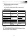
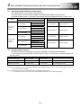
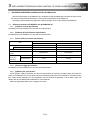
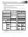
Store and use the unit in the following environmental conditions.
Environment
Ambient
temperature
Ambient humidity
Storage
temperature
Atmosphere
Conditions
Motion controller/Servo amplifier
According to each instruction manual.
According to each instruction manual.
According to each instruction manual.
Servomotor
0°C to +40°C (With no freezing)
(32°F to +104°F)
80% RH or less
(With no dew condensation)
-20°C to +65°C
(-4°F to +149°F)
Indoors (where not subject to direct sunlight).
No corrosive gases, flammable gases, oil mist or dust must exist
Altitude
1000m (3280.84ft.) or less above sea level
Vibration
According to each instruction manual
When coupling with the synchronous encoder or servomotor shaft end, do not apply impact such
as by hitting with a hammer. Doing so may lead to detector damage.
Do not apply a load larger than the tolerable load onto the synchronous encoder and servomotor
shaft. Doing so may lead to shaft breakage.
When not using the module for a long time, disconnect the power line from the Motion controller
or servo amplifier.
Place the Motion controller and servo amplifier in static electricity preventing vinyl bags and store.
When storing for a long time, please contact with our sales representative.
Also, execute a trial operation.
A- 6
(4) Wiring
CAUTION
Correctly and securely wire the wires. Reconfirm the connections for mistakes and the terminal
screws for tightness after wiring. Failing to do so may lead to run away of the servomotor.
After wiring, install the protective covers such as the terminal covers to the original positions.
Do not install a phase advancing capacitor, surge absorber or radio noise filter (option FR-BIF)
on the output side of the servo amplifier.
Correctly connect the output side (terminal U, V, W) and ground. Incorrect connections will lead
the servomotor to operate abnormally.
Do not connect a commercial power supply to the servomotor, as this may lead to trouble.
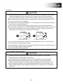
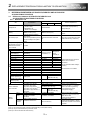
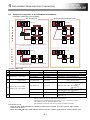
Do not mistake the direction of the surge absorbing diode installed on the DC relay for the control
signal output of brake signals, etc. Incorrect installation may lead to signals not being output
when trouble occurs or the protective functions not functioning.
Servo amplifier
DOCOM
Control output
signal
Servo amplifier
24VDC
DOCOM
Control output
signal
RA
DICOM
24VDC
RA
DICOM
For the sink output interface
For the source output interface
Do not connect or disconnect the connection cables between each unit, the encoder cable or
PLC expansion cable while the power is ON.
Securely tighten the cable connector fixing screws and fixing mechanisms. Insufficient fixing may
lead to the cables combing off during operation.
Do not bundle the power line or cables.
(5) Trial operation and adjustment
CAUTION
Confirm and adjust the program and each parameter before operation. Unpredictable
movements may occur depending on the machine.
Extreme adjustments and changes may lead to unstable operation, so never make them.
When using the absolute position system function, on starting up, and when the Motion
controller or absolute value motor has been replaced, always perform a home position return.
Before starting test operation, set the parameter speed limit value to the slowest value, and
make sure that operation can be stopped immediately by the forced stop, etc. if a hazardous
state occurs.
A- 7
(6) Usage methods
CAUTION
Immediately turn OFF the power if smoke, abnormal sounds or odors are emitted from the
Motion controller, servo amplifier or servomotor.
Always execute a test operation before starting actual operations after the program or
parameters have been changed or after maintenance and inspection.
Do not attempt to disassemble and repair the units excluding a qualified technician whom our
company recognized.
Do not make any modifications to the unit.
Keep the effect or electromagnetic obstacles to a minimum by installing a noise filter or by using
wire shields, etc. Electromagnetic obstacles may affect the electronic devices used near the
Motion controller or servo amplifier.
When using the CE Mark-compliant equipment, refer to this manual for the Motion controllers
and refer to the corresponding EMC guideline information for the servo amplifiers, inverters and
other equipment.
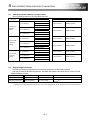
Use the units with the following conditions.
Item
Conditions
Input power
According to each instruction manual.
Input frequency
According to each instruction manual.
Tolerable momentary power failure
According to each instruction manual.
(7) Corrective actions for errors
CAUTION
If an error occurs in the self diagnosis of the Motion controller or servo amplifier, confirm the
check details according to the instruction manual, and restore the operation.
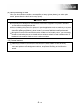
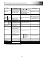
If a dangerous state is predicted in case of a power failure or product failure, use a servomotor
with electromagnetic brakes or install a brake mechanism externally.
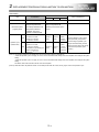
Use a double circuit construction so that the electromagnetic brake operation circuit can be
operated by emergency stop signals set externally.
Shut off with servo ON signal OFF,
alarm, electromagnetic brake signal.
Servomotor
RA1
Electromagnetic
brakes
Shut off with the
emergency stop
signal (EMG).
EMG
24VDC
If an error occurs, remove the cause, secure the safety and then resume operation after alarm
release.
The unit may suddenly resume operation after a power failure is restored, so do not go near the
machine. (Design the machine so that personal safety can be ensured even if the machine
restarts suddenly.)
A- 8
(8) Maintenance, inspection and part replacement
CAUTION
Perform the daily and periodic inspections according to the instruction manual.
Perform maintenance and inspection after backing up the program and parameters for the Motion
controller and servo amplifier.
Do not place fingers or hands in the clearance when opening or closing any opening.
Periodically replace consumable parts such as batteries according to the instruction manual.
Do not touch the lead sections such as ICs or the connector contacts.
Before touching the module, always touch grounded metal, etc. to discharge static electricity from
human body. Failure to do so may cause the module to fail or malfunction.
Do not directly touch the module's conductive parts and electronic components.
Touching them could cause an operation failure or give damage to the module.
Do not place the Motion controller or servo amplifier on metal that may cause a power leakage
or wood, plastic or vinyl that may cause static electricity buildup.
Do not perform a megger test (insulation resistance measurement) during inspection.
When replacing the Motion controller or servo amplifier, always set the new module settings
correctly.
When the Motion controller or absolute value motor has been replaced, carry out a home
position return operation using one of the following methods, otherwise position displacement
could occur.
1) After writing the servo data to the Motion controller using programming software, switch on the
power again, then perform a home position return operation.
2) Using the backup function of the programming software, load the data backed up before
replacement.
After maintenance and inspections are completed, confirm that the position detection of the
absolute position detector function is correct.
Do not drop or impact the battery installed to the module.
Doing so may damage the battery, causing battery liquid to leak in the battery. Do not use the
dropped or impacted battery, but dispose of it.
Do not short circuit, charge, overheat, incinerate or disassemble the batteries.
The electrolytic capacitor will generate gas during a fault, so do not place your face near the
Motion controller or servo amplifier.
The electrolytic capacitor and fan will deteriorate. Periodically replace these to prevent secondary
damage from faults. Replacements can be made by our sales representative.
Lock the control panel and prevent access to those who are not certified to handle or install
electric equipment.
Do not burn or break a module and servo amplifier. Doing so may cause a toxic gas.
A- 9
(9) About processing of waste
When you discard Motion controller, servo amplifier, a battery (primary battery) and other option
articles, please follow the law of each country (area).
CAUTION
This product is not designed or manufactured to be used in equipment or systems in situations
that can affect or endanger human life.
When considering this product for operation in special applications such as machinery or systems
used in passenger transportation, medical, aerospace, atomic power, electric power, or
submarine repeating applications, please contact your nearest Mitsubishi sales representative.
Although this product was manufactured under conditions of strict quality control, you are strongly
advised to install safety devices to forestall serious accidents when it is used in facilities where a
breakdown in the product is likely to cause a serious accident.
(10) General cautions
All drawings provided in the instruction manual show the state with the covers and safety
partitions removed to explain detailed sections. When operating the product, always return the
covers and partitions to the designated positions, and operate according to the instruction
manual.
A- 10
REVISIONS
Print Date
Oct.,2014
* Manual Number
L(NA)03104ENG-C
* The manual number is given on the bottom left of the back cover.
Revision
First edition
Based on L(NA)03079-C(Japanese)
This manual confers no industrial property rights or any rights of any other kind, nor does it confer any patent licenses.
Mitsubishi Electric Corporation cannot be held responsible for any problems involving industrial property rights which
may occur as a result of using the contents noted in this manual.
2013 MITSUBISHI ELECTRIC CORPORATION
A- 11
< GUIDEBOOK CONFIGURATION >
The guidebook is consist of the documents as follows.
Contents
Safety Precautions
Guidebook Configuration (Contents)
1. OVERVIEW OF A-MOTION REPLACEMENT
This overview is beginning with the case study about the system replacement used A-Motion. And it will
discuss the most suitable method according to the user’s system and conditions. After replacement policy
have been decided, it is recommended to replace refer to the corresponding parts after section 2 and the
relevant catalogs, relevant manuals.
2. REPLACEMENT PROPOSAL FROM A-MOTION TO QDS-MOTION
This part describes the replacement from A173UHCPU/A172SHCPUN/A171SHCPUN to
Q173DSCPU/Q172DSCPU (operating system software is SV13/SV22).
3. REPLACEMENT PROPOSAL FROM A-MOTION TO STAND-ALONE MOTION
This part describes the replacement from A173UHCPU/A172SHCPUN/A171SHCPUN to Q170MCPUS1 (operating system software is SV13/SV22).
4. REPLACEMENT FROM A-MOTION TO QN-MOTION
This part describes the replacement from A173UHCPU/A172SHCPUN/A171SHCPUN to
Q173CPUN/Q172CPUN (QN-Motion) (operating system software is SV13/SV22). However, replacing AMotion with QN-Motion is not recommended since QN-Motion is not the latest model. In order to use a
system for a long time after the replacement, it is recommended to replace A-Motion with QDS-Motion or
Stand-alone Motion.
5. APPENDIX
A- 12
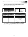
CONTENTS
Safety Precautions ····················································································································· A-1
Revisions································································································································ A-11
Guidebook Configuration ··········································································································· A-12
Contents································································································································· A-13
1. OVERVIEW OF A-MOTION REPLACEMENT .................................................................................................... 1
1.
OVERVIEW OF A-MOTION REPLACEMENT HANDBOOK ...................................................................... 2
2.
MAIN REPLACEMENT TARGET MODEL ................................................................................................... 2
3.
MERITS OF REPLACEMENT ...................................................................................................................... 3
3.1
Multiple CPU System (QDS-Motion) with Q Series PLC Module ............................................................ 3
3.2
High-speed and High Performance of Motion CPU.................................................................................. 3
3.3
High-speed, Noise Free Communication by SSCNET III(/H)................................................................... 3
3.4
MR-J4 Amplifier + HG Servo Motor (QDS-Motion) .................................................................................. 3
3.5
Space Economization (Stand-alone Motion) ............................................................................................ 3
3.6
Decrease of Maintenance Cost ................................................................................................................. 4
4.
CASE AND STUDY OF A-MOTION REPLACEMENT ................................................................................ 5
4.1
1): Update at once to QDS-Motion/Stand-alone Motion + MR-J4-B ........................................................ 6
4.2
2): When only Controllers and Servo Amplifiers are Changed ................................................................ 7
4.3
3): Partial Update from MR-J2S-B to MR-J4-B......................................................................................... 8
4.4
4): Individual Replacement Support .......................................................................................................... 9
4.5
Others ....................................................................................................................................................... 10
4.5.1
Combination before/after controller replacement ............................................................................ 10
4.5.2
Combination of controller and servo amplifier ................................................................................. 11
5.
SYSTEM TRANSITION ............................................................................................................................... 12
5.1
Configuration of the System Using A-Motion (before transition) ............................................................ 12
5.2
Configuration of the System Using QDS-Motion (after transition) ......................................................... 13
5.3
Replace to Stand-alone Motion ............................................................................................................... 14
5.4
Transition of Other Configurations .......................................................................................................... 15
5.4.1
Combination of servo amplifier and servo motor ............................................................................ 15
5.4.2
Specification comparison of servo system network ........................................................................ 15
5.4.3
Support of operating system software ............................................................................................. 16
5.4.4
Correspondence of peripheral software .......................................................................................... 16
5.4.5
Outline of the motion data replacement flow ................................................................................... 17
5.4.6
Precautions for replacing motion data saved with DOS-version peripheral software.................... 17
5.4.7
Dimensions ....................................................................................................................................... 17
6.
TRANSITION OF THE PROGRAM ............................................................................................................ 18
6.1
Motion Project Diversion Function in MT Works2................................................................................... 19
6.1.1
Data list available for diversion or not.............................................................................................. 19
6.1.2
Motion program diversion procedure in MT Works2 ....................................................................... 20
6.2
Ladder Program Diversion Function in GX Works2 ............................................................................... 22
6.2.1
Ladder program diversion procedure in GX Works2 ...................................................................... 22
6.2.2
The process after diverting the ladder program in GX Works2 ...................................................... 24
6.3
Precautions of Program Transition.......................................................................................................... 25
6.3.1
Precautions of shared device memory transition between SCPU (PLC) and PCPU (Motion CPU)
.......................................................................................................................................................... 25
7.
RELEVANT DOCUMENTS ......................................................................................................................... 26
7.1
Relevant Catalogs.................................................................................................................................... 26
7.2
Relevant Manuals .................................................................................................................................... 27
A- 13
2. REPLACEMENT PROPOSAL FROM A-MOTION TO QDS-MOTION .............................................................. 1
1.
OVERVIEW ................................................................................................................................................... 3
2.
EQUIPMENT CONFIGURATION, AVAILABLE SOFTWARE ..................................................................... 3
2.1
Equipment Correspondence...................................................................................................................... 3
2.2
Servo Amplifier Correspondence .............................................................................................................. 4
2.3
Operating System Software Correspondence .......................................................................................... 5
2.4
Engineering Environment .......................................................................................................................... 5
3.
DIFFERENCES BETWEEN Q173DSCPU/Q172DSCPU AND A173UHCPU/
A172SHCPUN/A171SHCPUN...................................................................................................................... 6
3.1
Differences between Q173DSCPU/Q172DSCPU and A173UHCPU/A172SHCPUN/A171SHCPUN .. 6
3.1.1
Differences list .................................................................................................................................... 6
3.1.2
Difference between self diagnosis error and Motion (SFC) error history ......................................... 9
3.1.3
Item that is necessary to change/revise with the change of servo system network ...................... 10
3.2
Device Comparison ................................................................................................................................. 11
3.2.1
I/O device.......................................................................................................................................... 11
3.2.2
Internal relay ..................................................................................................................................... 11
3.2.3
Data register ..................................................................................................................................... 14
3.2.4
Motion register .................................................................................................................................. 17
3.2.5
Special relay ..................................................................................................................................... 18
3.2.6
Special register ................................................................................................................................. 20
3.2.7
Other devices ................................................................................................................................... 23
4.
DIVERSION OF PROJECT CREATED BY A173CPUN/A172CPUN ....................................................... 25
4.1
Data List Available for Diversion or Not (SV13/SV22)............................................................................ 25
4.2
Program Diversion Procedure in Motion CPU Side................................................................................ 27
4.2.1
Diversion procedure using MT Developer2 ..................................................................................... 27
4.2.2
Without using SFC ........................................................................................................................... 30
4.2.3
Precautions for diverting cam data .................................................................................................. 31
4.3
Program Diversion Procedure in PLC CPU Side ................................................................................... 32
4.3.1
Conversion procedure of a sequence project for QnUD(E)(H)CPU using GX Works2/
GX Developer ................................................................................................................................... 32
5.
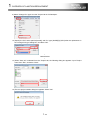
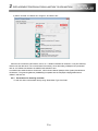
USING A/QnA->Q CONVERSION SUPPORT TOOL IN SEQUENCE PROGRAM ................................ 37
5.1
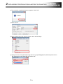
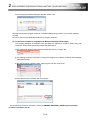
Preparation for Using Support Tool......................................................................................................... 37
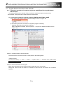
5.2
Using Procedure of Support Tool ............................................................................................................ 38
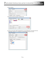
5.3
Sequence Program Correction in Created Embedding File ................................................................... 40
5.3.1
Correction of special relay/special register...................................................................................... 40
5.3.2
Correction of motion dedicated instructions .................................................................................... 40
5.3.3
Others ............................................................................................................................................... 40
6.
POINTS AND PRECAUTIONS OF REPLACEMENT ................................................................................ 41
6.1
Difference of Motion CPU Configuration ................................................................................................. 41
6.1.1
System configuration........................................................................................................................ 41
6.1.2
Shared device................................................................................................................................... 42
6.2
Precautions about Replacement ............................................................................................................. 43
6.2.1
Slot position (system setting) ........................................................................................................... 43
6.2.2
Communication data device between PLC CPU and Motion CPU ................................................ 44
6.2.3
Block number of refresh setting and total points number restriction .............................................. 46
6.2.4
Timer devices and counter devices ................................................................................................. 50
6.2.5
Indirect designation of servo program ............................................................................................. 50
6.2.6
Parameter block ............................................................................................................................... 51
A- 14
3. REPLACEMENT PROPOSAL FROM A-MOTION TO STAND-ALONE MOTION ...................................................... 1
1. OVERVIEW ....................................................................................................................................................... 3
2. EQUIPMENT CONFIGURATION, AVAILABLE SOFTWARE......................................................................... 3
2.1
Equipment Correspondence...................................................................................................................... 3
2.2
Servo Amplifier Correspondence .............................................................................................................. 4
2.3
Operating System Software Correspondence .......................................................................................... 5
2.4
Engineering Environment .......................................................................................................................... 5
3. DIFFERENCES BETWEEN Q170MSCPU(-S1) AND A173UHCPU/A172SHCPUN/A171SHCPUN ........... 6
3.1
Differences between Q170MSCPU(-S1) and A173UHCPU/A172SHCPUN/A171SHCPUN ................. 6
Differences list ................................................................................................................................................... 6
Difference between self diagnosis error and Motion (SFC) error history ...................................................... 10
Item that is necessary to change/revise with the change of servo system network ..................................... 11
3.2
Device Comparison ................................................................................................................................. 12
3.2.1
I/O device.......................................................................................................................................... 12
3.2.2
Internal relay ..................................................................................................................................... 12
3.2.3
Data register ..................................................................................................................................... 16
3.2.4
Motion register .................................................................................................................................. 19
3.2.5
Special relay ..................................................................................................................................... 20
3.2.6
Special register ................................................................................................................................. 22
3.2.7
Other devices ................................................................................................................................... 25
4. DIVERSION OF PROJECT CREATED BY A173UHCPU/A172SHCPUN/A171SHCPUN.......................... 27
4.1
Data List Available for Diversion or Not (SV13/SV22)............................................................................ 27
4.2
Program Diversion Procedure in Motion CPU Side................................................................................ 29
4.2.1
Diversion procedure using MT Developer2 ..................................................................................... 29
4.2.2
Without using SFC ........................................................................................................................... 32
4.2.3
Precautions for diverting cam data .................................................................................................. 33
4.3
Program Diversion Procedure in PLC CPU Side ................................................................................... 34
4.3.1
Conversion procedure of ladder program for QnUD(H)CPU using GX Works2/GX Developer ... 34
5. USING A/QnA->Q CONVERSION SUPPORT TOOL IN LADDER PROGRAM .......................................... 39
6. POINTS AND PRECAUTIONS OF REPLACEMENT ................................................................................... 39
6.1
Difference of Motion CPU Configuration ................................................................................................. 39
6.1.1
System configuration........................................................................................................................ 39
6.2
Precautions about Replacement ............................................................................................................. 40
6.2.1
Slot position (system configuration) ................................................................................................. 40
7. DIFFERENCE BETWEEN Q170MSCPU AND Q170MSCPU-S1 ................................................................ 42
7.1
Difference between Q170MSCPU and Q170MSCPU-S1...................................................................... 42
7.1.1
(1) Motion control specification ........................................................................................................ 42
7.1.2
(2) Motion SFC performance specification ...................................................................................... 42
7.1.3
(3) PLC CPU part control specification ............................................................................................ 42
7.1.4
(4) Power supply specification ......................................................................................................... 42
7.1.5
(5) Battery life specification .............................................................................................................. 42
A- 15
4. REPLACEMENT FROM A-MOTION TO QN-MOTION .................................................................................................... 1
1. OVERVIEW ....................................................................................................................................................... 3
2. EQUIPMENT CONFIGURATION, AVAILABLE SOFTWARE......................................................................... 3
2.1
Equipment Correspondence...................................................................................................................... 3
2.2
Equipment Configuration of Q173CPUN/Q172CPUN Motion ................................................................. 5
2.3
Operating System Software Correspondence .......................................................................................... 7
2.4
Engineering Environment .......................................................................................................................... 7
3. DIFFERENCES BETWEEN Q173CPUN/Q172CPUN AND A173UHCPU/A172SHCPUN/A171SHCPUN . 8
3.1
Differences between Q173CPUN/Q172CPUN and A173UHCPU/A172SHCPUN/A171SHCPUN ....... 8
3.1.1
Differences list .................................................................................................................................... 8
3.1.2
Differences between self diagnosis error and Motion (SFC) error history ..................................... 11
3.1.3
Items required to be changed/revised with the servo system network change ............................. 12
3.2
Device Comparison ................................................................................................................................. 13
3.2.1
I/O device.......................................................................................................................................... 13
3.2.2
Internal relay ..................................................................................................................................... 13
3.2.3
Data register ..................................................................................................................................... 16
3.2.4
Motion register .................................................................................................................................. 19
3.2.5
Special relay ..................................................................................................................................... 20
3.2.6
Special register ................................................................................................................................. 22
3.2.7
Other devices ................................................................................................................................... 25
4. DIVERSION OF PROJECT CREATED WITH A173CPUN/A172CPUN ...................................................... 27
4.1
List of Available Data for Diversion (SV13/SV22)................................................................................... 27
4.2
Program Diversion Procedure in Motion CPU Side................................................................................ 29
4.2.1
Diversion procedure using MT Developer2 ..................................................................................... 29
4.2.2
When SFC is not used ..................................................................................................................... 32
4.2.3
Precautions for diverting cam data .................................................................................................. 32
4.3
Program Diversion Procedure in PLC CPU Side ................................................................................... 33
4.3.1
Conversion procedure of sequence program for Qn(H)CPU using GX Works2/ GX Developer .. 33
5. USING A/QnA->Q CONVERSION SUPPORT TOOL FOR SEQUENCE PROGRAMS ............................. 38
5.1
Preparation for Using Support Tool......................................................................................................... 38
5.2
Using Procedure of Support Tool ............................................................................................................ 39
5.3
Correction of the Sequence Program in Created Embedded File ......................................................... 41
5.3.1
Correction of special relay/special register...................................................................................... 41
5.3.2
Correction of motion-dedicated instructions .................................................................................... 41
5.3.3
Others ............................................................................................................................................... 41
6. POINTS AND PRECAUTIONS OF REPLACEMENT ................................................................................... 42
6.1
Difference of Motion CPU Configuration ................................................................................................. 42
6.1.1
System configuration........................................................................................................................ 42
6.1.2
Shared device................................................................................................................................... 43
6.2
Precautions on Replacement .................................................................................................................. 44
6.2.1
Slot position (system setting) ........................................................................................................... 44
6.2.2
Restrictions on the number of blocks and total points in the refresh setting .................................. 45
6.2.3
Timer counter ................................................................................................................................... 45
6.2.4
Parameter block ............................................................................................................................... 45
A- 16
5. APPENDIX ······························································································································· 1
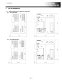
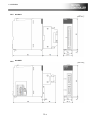
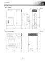
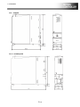
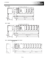
1. OUTLINE DIMENSIONS................................................................................................................................... 2
1.1
Outline Dimensions of A Series (small type) ··········································································· 2
1.1.1
A17nSHCPUN .................................................................................................................................... 2
1.1.2
A173UHCPU(-S1) .............................................................................................................................. 2
1.1.3
A172SENC ......................................................................................................................................... 3
1.1.4
A172B ................................................................................................................................................. 3
1.1.5
A175B ................................................................................................................................................. 4
1.1.6
A178B(-S□) ......................................................................................................................................... 4
1.1.7
A168B ................................................................................................................................................. 4
1.1.8
A1S65B............................................................................................................................................... 5
1.1.9
A1S68B............................................................................................................................................... 5
1.2
Outline Dimensions of QD(S) Series ····················································································· 6
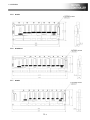
1.2.1
Q17nDSCPU ...................................................................................................................................... 6
1.2.2
Q17nDCPU......................................................................................................................................... 6
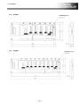
1.2.3
Q17nDCPU-S1 ................................................................................................................................... 7
1.2.4
Q170DBATC ...................................................................................................................................... 7
1.2.5
Q172DLX ............................................................................................................................................ 8
1.2.6
Q172DEX ........................................................................................................................................... 8
1.2.7
Q173DPX ........................................................................................................................................... 9
1.2.8
Q61P/Q62P/Q63P.............................................................................................................................. 9
1.2.9
QnHCPU........................................................................................................................................... 10
1.2.10 QnUDE(H)CPU ................................................................................................................................ 10
1.2.11 Q38DB .............................................................................................................................................. 11
1.2.12 Q312DB ............................................................................................................................................ 11
1.2.13 Q55B ................................................................................................................................................. 11
1.2.14 Q63B ................................................................................................................................................. 12
1.2.15 Q65B ................................................................................................................................................. 12
1.2.16 Q68B [Base unit mounting hole: 5 holes] ........................................................................................ 12
1.2.17 Q68B [Base unit mounting hole: 4 holes] ........................................................................................ 13
1.2.18 Q612B [Base unit mounting hole: 5 holes] ...................................................................................... 13
1.2.19
Q612B [Base unit mounting hole: 4 holes] ..................................................................................... 13
1.3
Outline Dimensions of Stand-alone Motion ·········································································· 14
1.3.1
Q170MSCPU(-S1) ........................................................................................................................... 14
1.3.2
Q170MCPU ...................................................................................................................................... 14
A- 17
Memo
A- 18
1
. OVERVIEW OF A-MOTION REPLACEMENT
1. OVERVIEW OF A-MOTION REPLACEMENT
1. OVERVIEW OF A-MOTION REPLACEMENT .................................................................................................... 1
1.
OVERVIEW OF A-MOTION REPLACEMENT HANDBOOK ...................................................................... 2
2.
MAIN REPLACEMENT TARGET MODEL ................................................................................................... 2
3.
MERITS OF REPLACEMENT ...................................................................................................................... 3
3.1
Multiple CPU System (QDS-Motion) with Q Series PLC Module ............................................................ 3
3.2
High-speed and High Performance of Motion CPU.................................................................................. 3
3.3
High-speed, Noise Free Communication by SSCNET III(/H)................................................................... 3
3.4
MR-J4 Amplifier + HG Servo Motor (QDS-Motion)................................................................................... 3
3.5
Space Economization (Stand-alone Motion) ............................................................................................ 3
3.6
Decrease of Maintenance Cost ................................................................................................................. 4
4.
CASE AND STUDY OF A-MOTION REPLACEMENT ................................................................................ 5
4.1
1): Update at once to QDS-Motion/Stand-alone Motion + MR-J4-B ........................................................ 6
4.2
2): When only Controllers and Servo Amplifiers are Changed ................................................................ 7
4.3
3): Partial Update from MR-J2S-B to MR-J4-B ......................................................................................... 8
4.4
4): Individual Replacement Support .......................................................................................................... 9
4.5
Others ....................................................................................................................................................... 10
4.5.1
Combination before/after controller replacement ............................................................................ 10
4.5.2
Combination of controller and servo amplifier ................................................................................. 11
5.
SYSTEM TRANSITION ............................................................................................................................... 12
5.1
Configuration of the System Using A-Motion (before transition) ............................................................ 12
5.2
Configuration of the System Using QDS-Motion (after transition) ......................................................... 13
5.3
Replace to Stand-alone Motion ............................................................................................................... 14
5.4
Transition of Other Configurations .......................................................................................................... 15
5.4.1
Combination of servo amplifier and servo motor ............................................................................ 15
5.4.2
Specification comparison of servo system network ........................................................................ 15
5.4.3
Support of operating system software ............................................................................................. 16
5.4.4
Correspondence of peripheral software .......................................................................................... 16
5.4.5
Outline of the motion data replacement flow ................................................................................... 17
5.4.6
Precautions for replacing motion data saved with DOS-version peripheral software.................... 17
5.4.7
Dimensions ....................................................................................................................................... 17
6.
TRANSITION OF THE PROGRAM ............................................................................................................ 18
6.1
Motion Project Diversion Function in MT Works2................................................................................... 19
6.1.1
Data list available for diversion or not .............................................................................................. 19
6.1.2
Motion program diversion procedure in MT Works2 ....................................................................... 20
6.2
Ladder Program Diversion Function in GX Works2 ............................................................................... 22
6.2.1
Ladder program diversion procedure in GX Works2 ...................................................................... 22
6.2.2
The process after diverting the ladder program in GX Works2 ...................................................... 24
6.3
Precautions of Program Transition .......................................................................................................... 25
6.3.1
Precautions of shared device memory transition between SCPU (PLC) and PCPU (Motion CPU)
.......................................................................................................................................................... 25
7.
RELEVANT DOCUMENTS ......................................................................................................................... 26
7.1
Relevant Catalogs.................................................................................................................................... 26
7.2
Relevant Manuals .................................................................................................................................... 27
1- 1
1
. OVERVIEW OF A-MOTION REPLACEMENT
1.
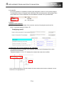
OVERVIEW OF A-MOTION REPLACEMENT HANDBOOK
The following shows the essential replacement overview to renew or lengthen the working life for the
system which used A-Motion.
After replacement policy have been decided, it is recommended to replace refer to the corresponding
part of continuous replacement handbook, technical sheet and the manual for each model.
Mitsubishi Motion Controller
A series (small type) ("A-Motion")
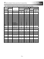
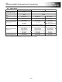
2.
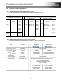
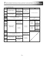
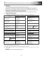
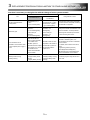
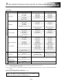
MAIN REPLACEMENT TARGET MODEL
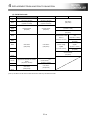
The main replacement target model is A series (small type) motion controllers and these options.
The motion controllers and related models that displayed in the following table have switched to the
production to the order already, it is recommended to replace (transit) to the new model.
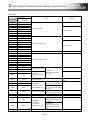
Product
CPU module
Model name
Product
A171SHCPUN
A30TU
A172SHCPUN
A30TU-E
A30TU-S1
A173UHCPU(Note-1)
Main base unit
Model name
A30TU-SV42
A172B
A30TU-SV51
A175B
A31TU
A178B
Teaching unit
A178B-S1
A31TU-E
A31TU-KE
A178B-S2
A31TU-R
A178B-S3
A31TU-RE
PLC extension base unit
A168B
A31TU-RT
Pulse generator/synchronous encoder
A171SENC
A31TU-RTE
interface module
A172SENC
A31TU-D3KE51
Cable for SSCNET I/F board
A270BDCBL□M
A31TU-D3RKE51
Cable for SSCNET I/F card
A270CDCBL□M
Teaching unit
connection cable
A31TUCBL using short circuit
connector
A31TUCBL03M
A31SHORTCON
(Note-1): A173UHCPU-S1 also be shown as A173UHCPU in the article.
* In addition, the targets are controller OS package used in above products, software tool packages and the customized
products which were derived from these products.
1- 2
1
. OVERVIEW OF A-MOTION REPLACEMENT
3.
MERITS OF REPLACEMENT
It is recommended to replace A-Motion to the latest iQ Platform Motion CPU Q173DSCPU/Q172DSCPU
(the following QDS-Motion) or Stand-alone Motion CPU Q170MSCPU-S1.
As the merits shown below, it is strongly recommended to use the latest module, QDS-Motion and
MR-J4 amplifier.
When a servo network cannot be replaced and A-Motion is replaced with Q173CPUN/Q172CPUN
(hereafter called QN-Motion), refer to "4. REPLACEMENT FROM A-MOTION TO QN-MOTION". However,
replacing A-Motion with QN-Motion is not recommended since QN-Motion is not the latest model. In
addition, the production of MR-J2S series servo amplifiers and HC series servo motors will stop in August,
2015. If these products need to be continuously used after the production stoppage, changing the system
used to an alternative system will be required. (For details, refer to Section 4.2 to 4.3.)
In order to use a system for a long time with no system modification after the replacement, it is
recommended to replace A-Motion with QDS-Motion or Stand-alone Motion.
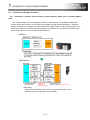
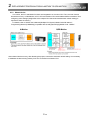
3.1
Multiple CPU System (QDS-Motion) with Q Series PLC Module
A system with high flexibility and extensibility can be constructed using various iQ Platform-compatible
modules. An equipment that match the varied request by extensive products can be selected.
--> Takt time of Production line will be shorten by the equipment capability of expansion and high
performance.
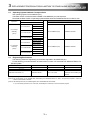
3.2
High-speed and High Performance of Motion CPU
The operation speed of a Motion CPU can be significantly improved: a Motion CPU has an operation
cycle of up to 0.22ms/4 axes (QDS-Motion SV22) or 0.44ms/4 axes (Stand-alone Motion SV22). And as
there are extremely abundant motion control functions, it can support the advanced motion control.
--> Takt time of Production line will be shorten by the high-speed motion control capability and
high performance.
3.3
High-speed, Noise Free Communication by SSCNET III(/H)
SSCNET III(/H) Servo network communication realizes high-speed response (Communication speed:
150Mbps (simplex)/300Mbps (duplex)) and eliminates the influence of noise by utilizing an optical
communication system.
--> The influence of noise by wiring can be suppressed, and the operation of equipment will be
stabilized.
3.4
MR-J4 Amplifier + HG Servo Motor (QDS-Motion)
The latest MR-J4 series includes various functions such as one-touch tuning and realizes the high
performance with speed response frequency of 2.5 kHz and encoder resolution of 22 bits (4194304
pulses/rev). The quantity of rare earth metals is reduced for HG series, the servo motor series appropriate
for QDS-Motion.
--> The influence of noise by wiring can be suppressed, and the operation of equipment will be
stabilized.
3.5
Space Economization (Stand-alone Motion)
A power supply module, a PLC, and a motion controller are integrated without degrading the high
performance of iQ Platform, and this contributes cost reduction and downsizing the equipment. Built the
mark detection and the synchronous encoder I/F in, and it will support the packing machine system without
using special module.
--> Small-size equipment and cost performance will be compatible.
1- 3
1
. OVERVIEW OF A-MOTION REPLACEMENT
3.6
Decrease of Maintenance Cost
Once the product has been used for more than 5 years, it is necessary to maintain the machine such as
partly replacement according to the lifespan, and the maintenance cost for power supply module replacing,
electrolytic capacitor and the whole board replacing will be charged. In order to use the system for a long
time, and consider the factors like performance and quality, it is recommended to replace to the latest
model at early stage.
--> Extend the lifespan of the equipment.
1- 4
1
. OVERVIEW OF A-MOTION REPLACEMENT
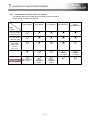
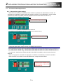
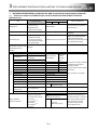
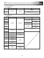
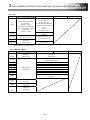
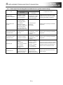
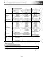
4.
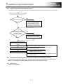
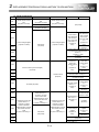
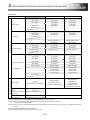
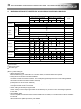
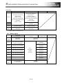
CASE AND STUDY OF A-MOTION REPLACEMENT
The following shows the replacement case study of the system which used standard A-Motion. Although
it will need some major maintenance, it is recommended to carry out the system batch update of 1) to use a
system for a long time with no system modification after the maintenance.
If the batch update including the change of servo amplifiers, servo motors, and servo networks is difficult
to carry out due to the period and cost of the maintenance, carry out 2) or 3). If any update will not be done,
refer to 4) Individual replacement support.
A171SHCPUN
A172SHCPUN
A173UHCPU
MR-J2S-B
* Production will be stopped in August, 2015.
Case 1) to 4) will be explained on
the next page and later.
HC/HA motor
* Production will be
stopped in August, 2015.
YES
System update at once
YES
NO
Change controllers
and servo amplifiers
YES
1) Update at once to
QDS-Motion + MR-J4-B or
Stand-alone Motion +
MR-J4-B
2) Drive HC/HA
motors using 1).
NO
Change servo amplifiers
and servo motors
3) Partially change to
MR-J4-B and change
to the latest motion
controllers finally.
4) Individual
replacement support
• Servo amplifier
• Motor
Only when equipment is completely replaced.
*1. Although it will cost a lot and take a long period for maintenance, once a system is upgraded,
the system can be used for a long time after that.
1- 5
1
. OVERVIEW OF A-MOTION REPLACEMENT
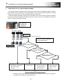
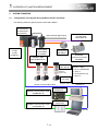
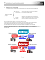
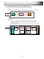
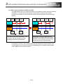
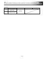
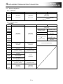
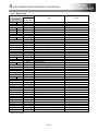
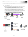
4.1
1): Update at once to QDS-Motion/Stand-alone Motion + MR-J4-B
The following shows the systems for the system batch update.
[QDS-Motion + MR-J4-B + HG motor]
[Stand-alone Motion + MR-J4-B + HG motor]
QnUD PLC + QDS-Motion + Q3□DB base
Q170MSCPU(-S1)
MR-J4-B
MR-J4-B
HG motor
HG motor
"QDS-Motion" is point to the following modules.
Q172DSCPU, Q173DSCPU
"Stand-alone Motion" is point to the following
modules.
Q170MSCPU, Q170MSCPU -S1
1- 6
1
. OVERVIEW OF A-MOTION REPLACEMENT
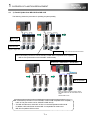
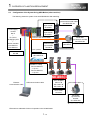
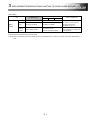
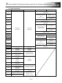
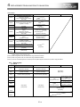
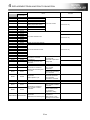
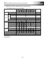
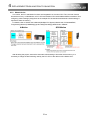
4.2
2): When only Controllers and Servo Amplifiers are Changed
The following shows the procedure for updating a system when only controllers and servo amplifiers are
changed.
[QDS-Motion + MR-J4-B + HC/HA motor]
[Stand-alone Motion + MR-J4-B
+ HC/HA motor]
QnUD PLC + QDS-Motion + Q3□DB base
Q170MSCPU(-S1)
MR-J4-B
MR-J4-B
HC/HA motor
"QDS-Motion" indicates the following modules.
Q172DSCPU, Q173DSCPU
"Stand-alone Motion" indicates the following modules.
Q170MSCPU, Q170MSCPU-S1
* Although HC/HA motors can be used without any change, the encoder resolution of the servo amplifier
becomes 17 bits.
For the applicable servo motors and servo amplifiers, contact your local sales office.
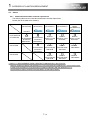
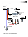
POINT
● When the following HC/HA motors are used, changing the motors with HG motors and
servo amplifiers with MR-J4-_B_ in a batch is recommended.
(To use HG motors, the capacity of servo amplifiers may need to be changed.)
Existing model
Servo motor
Servo amplifier
MR-J2S-60B
HC-LFS52
MR-J2S-100B
HC-LFS102
MR-J2S-200B
HC-LFS152
MR-J2S-15KB(4)
HA-LFS15K2(4)(B)
MR-J2S-22KB(4)
HA-LFS22K2(4)(B)
MR-J2S-30KB(4)
HA-LFS30K2(4)
MR-J2S-70B
HC-KFS46
MR-J2S-70B
HC-KFS410
HC-RFS103(B)G2 1/_ MR-J2S-200B
HC-RFS203(B)G2 1/_ MR-J2S-350B
HC-RFS353(B)G2 1/_ MR-J2S-500B
HC-RFS103(B)G5 1/_ MR-J2S-200B
HC-RFS203(B)G5 1/_ MR-J2S-350B
HC-RFS353(B)G5 1/_ MR-J2S-500B
HC-RFS103(B)G7 1/_ MR-J2S-200B
HC-RFS203(B)G7 1/_ MR-J2S-350B
HC-RFS353(B)G7 1/_ MR-J2S-500B
Example of replacement models for batch change
Servo motor
Servo amplifier
HG-JR73
MR-J4-70B
HG-JR153
MR-J4-200B
HG-JR353
MR-J4-350B
HG-JR11K1M(4)(B)
MR-J4-11KB(4)
HG-JR15K1M(4)(B)
MR-J4-15KB(4)
HG-JR22K1M(4)
MR-J4-22KB(4)
HG-KR43
MR-J4-40B
HG-KR43
MR-J4-40B
HG-SR102(B)G7 1/_
MR-J4-100B
HG-SR202(B)G7 1/_
MR-J4-200B
HG-SR352(B)G7 1/_
MR-J4-350B
HG-SR102(B)G5 1/_
MR-J4-100B
HG-SR202(B)G5 1/_
MR-J4-200B
HG-SR352(B)G5 1/_
MR-J4-350B
HG-SR102(B)G7 1/_
MR-J4-100B
HG-SR202(B)G7 1/_
MR-J4-200B
HG-SR352(B)G7 1/_
MR-J4-350B
1- 7
1
. OVERVIEW OF A-MOTION REPLACEMENT
4.3
3): Partial Update from MR-J2S-B to MR-J4-B
The following shows the procedure for updating a system partially.
MR-J2S-B
* Production will be
stopped in August, 2015.
HC/HA motor
* Production will be
stopped in August, 2015.
HG motor
* MR-J2S-B cannot drive HG motors.
MR-J4-B-RJ020 (Conversion unit for SSCNET of MR-J2S-B compatible servo amplifier)
+ MR-J4-T20 (Conversion unit for SSCNET of MR-J2S-B)
QnUD PLC + QDS-Motion + Q3□DB base
MR-J4-B-RJ020
* When the network used is changed, change
MR-J4-B-RJ020 from the J2S mode to the J4
mode.
Remove MR-J4-T20.
MR-J4-B-RJ020 (Conversion unit for SSCNET of MR-J2S-B compatible servo amplifier)
+ MR-J4-T20 (Conversion unit for SSCNET of MR-J2S-B)
→ The MR-J4-B-RJ020 to which MR-J4-T20 is connected operates as MR-J2S-B.
In addition, MR-J4-B-RJ020 can drive MR-J4-compatible HG motors and
MR-J2S-compatible HC/HA motors.
1- 8
1
. OVERVIEW OF A-MOTION REPLACEMENT
4.4
4): Individual Replacement Support
The following shows the system update procedure for the individual replacement.
When a servo amplifier (MR-J2S-B) failed
When a servo motor failed
Change to
MR-J4-B-RJ020 +
MR-J4-T20.
Change to
MR-J4-B-RJ020 +
MR-J4-T20.
Change to an HG motor.
HC/HA motor
* Production will be stopped
in August, 2015.
Drive the HC/HA motor using MR-J4-B-RJ020
+ MR-J4-T20.
1- 9
Drive the HG motor using MR-J4-B-RJ020 +
MR-J4-T20.
* In addition to the failed servo motor, the servo
amplifier connected with the servo motor needs to
be changed in this case.
1
. OVERVIEW OF A-MOTION REPLACEMENT
4.5
Others
4.5.1 Combination before/after controller replacement
The following table shows combination before/after controller replacement.
Please refer to the table when transiting.
A-Motion
• A17nSHCPUN
• A173UHCPU
Q-Motion
• Q17nCPUN
QH-Motion
• Q17nHCPU
QN-Motion
(Q17nCPUN)
QH-Motion
(Q17nHCPU)
QD-Motion
(Q17nDCPU)
QDS-Motion
(Q17nDSCPU)
Stand-alone
Motion
(Q170MSCPU)
SSCNET
SSCNET III
SSCNET III
SSCNET III/H
SSCNET III/H
It is
recommended
to transit to
*1
QDS-Motion.
It is
recommended
to transit to
QDS-Motion.
Refer to
Section 2 in this
document.
Refer to
Section 2 in this
document.
Refer to
Section 3 in this
document.
It is
recommended
to transit to
QDS-Motion.
Refer to
Technical sheet:
S0014CB
Refer to
Technical sheet:
S0014CB
← Same as
QDS-Motion
Refer to
Technical sheet:
S0013CB
Refer to
Technical sheet:
S0013CB
← Same as
QDS-Motion
*1 Refer to "4. REPLACEMENT FROM A-MOTION TO QN-MOTION" in this document.
However, replacing A-Motion with QN-Motion is not recommended since QN-Motion is not the latest model.
In order to use a system for a long time with no system modification after the replacement, it is
recommended to replace A-Motion with QDS-Motion or Stand-alone Motion.
1- 10
1
. OVERVIEW OF A-MOTION REPLACEMENT
4.5.2 Combination of controller and servo amplifier
The following table shows combination of controller and servo amplifier.
Please refer to the table when transiting.
Controller
QN-Motion
(Q17nCPUN)
QH-Motion
(Q17nHCPU)
QD-Motion
(Q17nDCPU)
QDS-Motion
(Q17nDSCPU)
Stand-alone
Motion
(Q170MSCPU)
(Controller:
J3 mode)
(Controller:
J3 mode)
Servo
amplifier
MR-H-BN
Production stopped
in December, 2005.
MR-J2-B
Production stopped
in December, 2005.
MR-J2S-B
MR-J2M-B
Production will be
stopped in
August, 2015.
MR-J3-B
MR-J4-B
(MR-J4-B-RJ020
+MR-J4-T20)
(MR-J3
compatible
mode)
(MR-J3
compatible
mode)
1- 11
1
. OVERVIEW OF A-MOTION REPLACEMENT
5.
5.1
SYSTEM TRANSITION
Configuration of the System Using A-Motion (before transition)
The following shows the general system chart used A-Motion.
A171SHCPUN
A172SHCPUN
A173UHCPU
(Servo external signal input)
Main base unit
A172B
A175B
A178B(-S□)
Motion signal
input module
A172SENC
Serial ABS synchronous
encoder cable
MR-HSCBL□M
Manual pulse
MR-HDP01
Serial ABS
synchronous encoder
MR-HENC
SSCNET cable
MR-J2HBUS□M(-A)
Servo amplifier
MR-J2S-□B
* Production will be
stopped in
August, 2015.
Servo motor
HC motor
RS-422 communication cable
SSCNET communication cable
A270BDCBL□M
SSCNET communication cable
A270CDCBL□M
[SSCNET cable]
For A171/172SHCPUN,
••• Up to 1
For A173UHCPU(-S1),
••• Up to 4
* Production will be
stopped in August, 2015.
Desktop PC
SSCNET board
A30BD-PCF
SSCNET card
A30CD-PCF
Note PC
1- 12
1
. OVERVIEW OF A-MOTION REPLACEMENT
5.2
Configuration of the System Using QDS-Motion (after transition)
The following shows the system chart used QDS-Motion after transiting.
Encoder
input module
Q172DEX
Power supply
module
Q6□P
+
PLC CPU
QnUD(E)(H) CPU
+
Motion controller
Q172DSCPU
Q173DSCPU
Serial ABS
synchronous encoder cable
Q170ENCCBL□M
Pulse
input module
Q173DPX
Manual pulse generator
(cannot be used with Q173DPX)
External signal
input module
Q172DLX
Serial ABS
synchronous encoder
Q171ENC-W8
Manual pulse
MR-HDP01
(External signal input)
Input: 4 points
Main base unit
Q3□DB
SSCNET III cable:
MR-J3BUS□M
[SSCNET III cable]
For Q172DSCPU,
••• Up to 1
For Q173DSCPU,
••• Up to 2
Ethernet
communication cable
USB communication cable
Servo amplifier
MR-J4-□B
MR-J4W2-□B
MR-J4W3-□B
Servo motor
HG motor
Serial ABS
synchronous
encoder
Q171ENC-W8
* Ethernet is a trademark of Xerox Corporation in the United States.
1- 13
1
. OVERVIEW OF A-MOTION REPLACEMENT
5.3
Replace to Stand-alone Motion
The following shows the system chart used Stand-alone Motion after transiting.
SSCNET III/H
Stand-alone Motion:
Input: 4 points
Q170MSCPU
Manual pulse
Output: 2 points
Q170MSCPU-S1
MR-HDP01
(External signal input)
Extension cable
External signal
QC□B
input module
Q172DLX
Extension base
Q52B/Q55B
module (Up to 512 points)
SSCNET III cable
Servo amplifier
MR-J4-□B
MR-J4W2-□B
MR-J4W3-□B
Servo motor
HG motor
communication
/RS-232C cable
Q173DPX also can be used
Serial ABS
synchronous encoder
Q171ENC-W8
MR-J3BUS□M
USB communication cable
Pulse input module
(External signal input)
I/O module/Intelligent function
Ethernet
Note)
cable
* Ethernet is a trademark of Xerox Corporation in the United States.
1- 14
1
. OVERVIEW OF A-MOTION REPLACEMENT
5.4
Transition of Other Configurations
5.4.1 Combination of servo amplifier and servo motor
The following table shows the combination of servo amplifier and servo motor.
Please refer to the table when transiting.
Q17nDSCPU/Q170MSCPU
A17nSHCPUN/A173UHCPU(-S1)
Series
MR-J2S
Servo
Servo
amplifier
motor
MR-J2S-□B
Series
Q17nDCPU/Q170MCPU
Series
Servo
Servo
amplifier
motor
HC-KFS□
MR-J4
MR-J4-□B
HG-KR□
HC-MFS□
Series
MR-J4W2-□B
HG-MR□
MR-J4W3-□B
HC-SFS□
HC-LFS□
HC-RFS□
→
HA-LFS□
MR-J2M
MR-J2M-□DU
Series
Series
MR-J3
Series
Servo
Servo
amplifier
motor
MR-J3-□B
HF-KP□
MR-J3W-□B
HF-MP□
HG-SR□
MR-J3-□B-RJ006
HF-SP□
HG-RR□
MR-J3-□B-RJ004
HF-JP□
HG-UR□
MR-J3-□BS
HC-LP□
HG-JR□
HC-RP□
HC-UFS□
HC-UP□
HC-KFS□
HA-LP□
HC-MFS□
HC-UFS□
5.4.2 Specification comparison of servo system network
The following table shows the specification comparison of servo system network.
Please refer to the table when transiting.
Item
SSCNET
(A-Motion)
Communication cable
Metal cable
Communication speed
5,6Mbps
Cycle
Send
Receive
The maximum
number of axes of
each system
Communication
Distance
SSCNETIII
Optical fibre cable
3.55ms/7.11ms/14.2ms
3.55ms
3.55ms
8axes/system
Overall length 30m
SSCNETIII/H
50Mbps
150Mbps
0.44ms/0.88ms
0.22ms/0.44ms/0.88ms
0.44ms/0.88ms
0.22ms/0.44ms/0.88ms
16 axes/system
→
Standard code for inside panel or Standard cable for
outside panel
Up to 20m between stations
Maximum overall length is 320m
(20m × 16 axes)
[Long-distance cable]
Up to 50m between
stations
Maximum overall
length is 800m
(50m×16axes)
1- 15
[Long-distance cable]
Up to 100m between
stations
Maximum overall
length is 1600m
(100m×16axes)
1
. OVERVIEW OF A-MOTION REPLACEMENT
5.4.3 Support of operating system software
The following table shows the support of operating system software.
Please refer to the table when transiting.
CPU model
OS
Type
A173UHCPU
SV13
(-S1)
OS model
CPU model
SW2SRX-SV13B
Q173DSCPU
SW2NX-SV13B
OS
OS model
Type
CPU model
SV13
SW8DNC-SV13QJ
SV22
SW8DNC-SV22QJ
SW3RN-SV13B
Q173DCPU
(-S1)
OS
Type
OS model
SV13
SW8DNC-SV13QB
SV22
SW8DNC-SV22QA
SV43
SW7DNC-SV43QA
SV13
SW8DNC-SV13QD
SV22
SW8DNC-SV22QC
SV43
SW7DNC-SV43QC
SV13
SW8DNC-SV13QG
SV22
SW8DNC-SV22QF
SV43
SW7DNC-SV43QF
SW2SRX-SV22A
SV22
SW2NX-SV22A
SW3RN-SV22A
SV43
A172SHCPUN
SW2SRX-SV43A
SV43
SW2NX-SV43A
SW0SRX-SV13D
SV13
Q172DSCPU
SW0NX-SV13D
SV13
SW8DNC-SV13QL
SV22
SW8DNC-SV22QL
SW3RN-SV13D
SW0SRX-SV22C
SV22
Q172DCPU
(-S1)
→
SW0NX-SV22C
SW3RN-SV22C
SV43
A171SHCPUN
SV13
SV22
SV43
SW0SRX-SV43C
SV43
SW0NX-SV43C
SW0SRX-SV13G
Q170MSCPU
SW0NX-SV13G
SW0SRX-SV22F
SW0NX-SV22F
SW0SRX-SV43F
SV13
SW8DNC-SV13QN
SV22
SW8DNC-SV22QN
Q170MCPU
SV43
SW0NX-SV43F
*1 For A-Motion controllers, "Motion SFC-compatible OS" and "Motion SFC non-compatible OS" are
different OSs. For the motion controllers of the Q series or later, whether to use the Motion SFC or not
can be selected for the same OS.
5.4.4 Correspondence of peripheral software
The following table shows the correspondence of peripheral software.
Please refer to the table when transiting.
A17nSHCPUN/A173UHCPU(-S1)
Class
Type
Motion
SW2SRX-GSV□
program
SW2NX-GSV□
SW3RNC-GSV□
PLC
GX Developer
program
Servo
<MR Configurator>
amplifier
SETUP161□
Q series Motion CPU
Type
Comment
<MELSOFT MT Works2>
SW1DNC-MTW2-□
→
(note-1)
<MELSOFT GX Works2>
(note-2)
Please use the latest version
(note-2)
Please use the latest version
(note-3)
<MR Configurator2>
SW1DNC-MRC2-□
Please use the latest version
(Note-1) GX Developer is bundled in GX Works2.
(Note-2) As the latest versions of MT Works2 and GX Works2 have been released in Mitsubishi Electric
FA Site, update your software to the latest version.
(Note-3) MR Configurator2 is bundled in MT Works2.
1- 16
1
. OVERVIEW OF A-MOTION REPLACEMENT
5.4.5 Outline of the motion data replacement flow
The following flowchart describes the motion data replacement procedure when the data can be diverted.
Start
Does the motion data file exist?
YES
Is the motion data saved in
the computer where Windows-version
peripheral software
(MT Works2) is installed?
YES
NO
Read the motion data from the Motion
CPU by using Windows-version
peripheral software (SW3RN) or
DOS-version peripheral software
(SW2SRX(NX)), and save the data.
NO
Move the motion data to the computer
where Windows-version peripheral
software (MT Works2) is installed.
Convert the CPU using Windows-version
peripheral software (MT Works2) and save
the data.
Divert parameters and programs.
Create a program and perform debugging.
(Caution)
Windows-version peripheral software (SW3RN)
: A-Motion-compatible Windows-version peripheral software
SW3RN-GSV13P/GSV22P
DOS-version peripheral software (SW2SRX(NX))
: A-Motion-compatible DOS-version peripheral software
SW2SRX(NX)-GSV13P/GSV22P
Windows-version peripheral software (MTWorks2)
: Q-Motion-compatible Windows-version peripheral software "MTWorks2"
SW1DNC-MTW2-J
5.4.6 Precautions for replacing motion data saved with DOS-version peripheral software
The motion data saved with DOS-version peripheral software (SW2SRX/SW2NX-GSV13P/GSV22P) is
stored in "C:\GPP\USR\System name\Machine name". Extract the data from the folder.
5.4.7 Dimensions
Refer to "5. APPENDIX".
1- 17
1
. OVERVIEW OF A-MOTION REPLACEMENT
6.
TRANSITION OF THE PROGRAM
The section shows the content which converts A-Motion to Q17nDS (virtual mode switching type).
Motion part
(SFC/not SFC)
Use the project diversion function in MT Works2.
It can also be used without SFC.
PLC part
(Ladder)
Use the PLC type change function in GX Works2.
"A/QnA->Q conversion support tool" can be used to
confirm the modified content of ladder program.
Transition of A-Motion
program
When the ladder program A/QnA->Q conversion support tool used
"A/QnA->Q conversion support tool" can be used to confirm the modified content of ladder program.
Please download and install A/QnA->Q conversion support tool from Mitsubishi FA Site.
For details, please refer to the A/QnA->Q conversion support tool guidebook in the same page.
Although the ladder program has been converted following the procedure, it may not be operated correctly. For
the program modifications, please refer to “2. REPLACEMENT PROPOSAL FROM A-MOTION TO
QDS-MOTION”.
Before conversion
After conversion
A-Motion
Program
QDS-Motion
Program
Before conversion
After conversion
Ladder Program
for A
Ladder Program
for Q
1- 18
1
. OVERVIEW OF A-MOTION REPLACEMENT
6.1
Motion Project Diversion Function in MT Works2
6.1.1 Data list available for diversion or not
The following table shows the overview whether the data can be diverted or not for the diversion function
of motion project in MT Works2. The data may not be diverted for the case, but more than half can be
diverted.
For details, please refer to “2. REPLACEMENT PROPOSAL FROM A-MOTION TO QDS-MOTION”.
Data list available for diversion or not
System setting data
System
SV13
SV22
A173UHCPU
SV13
Axis data
data
Basic setting
(Multiple CPU etc. must be set)
Fixed parameter
(Change electronic gear)
Home position return data
JOG operation data
Servo parameter
setting
Besides MR-J2S:
, MR-J2S:
Parameter block
: Not use Motion SFC
Limit output data
: Use Motion SFC
Motion SFC parameter
Motion SFC program
Motion
Operation control program
SFC
program
Transition program
(Device must be revised)
(Device must be revised)
(Device must be revised)
Conversion data
(Data must be converted again)
Automatic numbering setting
Servo program
Mechanical
system
program
Mechanical edit data
(Device must be reviewed)
-
-
Mechanical conversion
(Data must be converted again)
data
Cam conversion data
SV22
(Servo amplifier has been converted to MR-J3-B/MR-J4-B after diverting)
High speed reading data
setting
Servo
A171SHCPUN, A172SHCPUN
-
-
Cam data
SW3RNC-GSVE only
Device memory
(# device only)
: Can be diverted (can be used directly)
: Data must be revised
: Must be set again
- : Data does not exist because it has not been used in diversion source (A-Motion).
1- 19
1
. OVERVIEW OF A-MOTION REPLACEMENT
6.1.2
Motion program diversion procedure in MT Works2
The following describes the procedure for diverting an A173UHCPU/A17nSHCPUN project using MT
Works2. For details, refer to "2. REPLACEMENT PROPOSAL FROM A-MOTION TO QDS-MOTION". For
details, please refer to “2. REPLACEMENT PROPOSAL FROM A-MOTION TO QDS-MOTION”
1) Start MT Developer2, and select "Divert File" --> "Diversion of Other Format Project" from the "Project"
tab.
2) Specify the CPU type, OS type, and operation method after the replacement in the "Diversion of Other
Format Project" dialog box, and select "Browse".
•
Omitted below
•
1- 20
1
. OVERVIEW OF A-MOTION REPLACEMENT
10) Input "Workspace Name", "Project Name", and "Title", and select "Save".
11) Select "Yes".
Please refer to "4.1 Data list available for diversion or not (SV13/SV22)", and set the data that cannot be
diverted if necessary. And for the multiple-CPU parameter setting, please refer to “2. REPLACEMENT
PROPOSAL FROM A-MOTION TO QDS-MOTION” and the user's manual for the using module.
1- 21
1
. OVERVIEW OF A-MOTION REPLACEMENT
6.2
Ladder Program Diversion Function in GX Works2
6.2.1
Ladder program diversion procedure in GX Works2
This section explains the conversion overview of a ladder program for A-Motion controller (SCPU). For
details of ladder program created by GX Developer, please refer to “2. REPLACEMENT PROPOSAL
FROM A-MOTION TO QDS-MOTION”.
1) After starting GX Works2, select "Start GX Developer" from the "Project" tab.
2) The following shows the conversion of ladder program created by SW3RNC-GSVE. (GPPA file format)
After GX Works2/GX Developer is started, select "Import file" --> "Import from GPPA format file" from
the "Project" tab.
•
Omitted below
•
1- 22
1
. OVERVIEW OF A-MOTION REPLACEMENT
9) Select "Change PLC type" from the "Project" tab in GX Developer.
10) Specify the PLC series (QCPU(Qmode)) and PLC type (QnUD(E)(H)CPU) after the replacement in
the "Change PLC type" dialog box, and select "OK".
•
Omitted below
•
14) When "Save as" is selected from the "Project" tab, the following dialog box appears. Input "Project
name" and "Title", and select "Save".
15) The new project creation dialog box appears. Select "Yes".
1- 23
1
. OVERVIEW OF A-MOTION REPLACEMENT
6.2.2
The process after diverting the ladder program in GX Works2
Although the ladder program has been diverted by GX Works2, the dedicated instructions and dedicated
devices for A-Motion may not be converted automatically, please correct it manually as follows. And, there
is also a tool called" A/QnA->Q conversion support tool" to support the process.
For details, please refer to “2. REPLACEMENT PROPOSAL FROM A-MOTION TO QDS-MOTION”.
1) Motion dedicated instructions
(SVST, CHGA, CHGV, CHGT, SFCS, ITP)
--> Convert to SM1255.
2) A-Motion dedicated (not included in QDS-Motion)
• Special relay
• Special register
--> Convert to SM1255 and SD1255.
As it has been converted as above, please remember using content of these devices in the
pre-converted program (A-Motion ladder), and change the converted content in SM1255, SD1255 to
Q17nDSCPU Motion dedicated instructions and other bit device after converting. (Please refer to the user's
manual of each CPU module and the programming manual)
• QDS-Motion (Ladder)
• A-Motion (Ladder)
Convert
1) Motion dedicated instructions
(SVST, CHGA, CHGV, CHGT, SFCS, ITP)
2) A-Motion dedicated (not included in QDS-Motion)
• Special relay
• Special register
SM1255
SD1255
As it has been converted as above, please remember using content of these devices in the
pre-converted program (A-Motion ladder), and change the converted content in SM1255,
SD1255 to Q17nDSCPU Motion dedicated instructions and other bit device after
converting.
1- 24
1
. OVERVIEW OF A-MOTION REPLACEMENT
6.3
Precautions of Program Transition
6.3.1
CPU)
Precautions of shared device memory transition between SCPU (PLC) and PCPU (Motion
PLC CPU and Motion CPU are integrated in A-Motion, while these are not integrated in QDS-Motion.
And the shared device memory can be used by the Multiple CPU high speed transmission (+ automatic
refresh). Therefore it is necessary to execute the automatic refresh setting and allocate to the Motion CPU
device which used PLC CPU after the project diversion. Pay attention to the number of automatic refresh
block because the limit is 32 in Q173DSCPU/Q172DSCPU.
A-Motion
QDS-Motion
Q Bus
Automatic Refresh
(per scan time)
High
Speed Bus
(0.88ms
cyclical transition)
Automatic Refresh
(per main cycle/per operation cycle)
[Advantage]
- 0.88ms cyclical transition can be done in high speed transmission area
- Automatic refresh per operation cycle is possible
1- 25
1
. OVERVIEW OF A-MOTION REPLACEMENT
7.
7.1
RELEVANT DOCUMENTS
Please refer to the following documents. And it can be downloaded from Mitsubishi Electric FA Site
whenever you want.
Relevant Catalogs
Motion Controller Q17nDSCPU/Q170MSCPU,
Motion Controller
Simple Motion Module QD77MS/QD77GF
Q17nDCPU
L(NA) 03062
L(NA)03036
MELSERVO-J4
MELSERVO-J2-Super Transition Guide
L(NA) 03058
L(NA)03091
1- 26
1
. OVERVIEW OF A-MOTION REPLACEMENT
7.2
Relevant Manuals
Q170M(S) Series User's Manual
Q170MSCPU User's Manual
IB-0300212
Q173D(S)/Q172D(S) Series User's Manual
Q173D(S)CPU/Q172D(S)CPU User's Manual
IB-0300133
Q173D(S)/Q172D(S) Series Programming Manual
Programming Manual (COMMON) [type Q173D(S)/Q172D(S)]
IB-0300134
Q173D(S)/Q172D(S) Series Programming Manual
SV13/22Programming Manual (Motion SFC) [type Q173D(S)/Q172D(S)]
IB-0300135
Q173D(S)/Q172D(S) Series Programming Manual
SV13/22Programming Manual (REAL MODE) [type Q173D(S)/Q172D(S)]
IB-0300136
Q173D(S)/Q172D(S) Series Programming Manual
SV22Programming Manual (VIRTUAL MODE) [type Q173D(S)/Q172D(S)]
IB-0300137
Q173D(S)/Q172D(S) Series Programming Manual
SV22Programming Manual (Advanced Synchronous Control) [type Q173DS/Q172DS]
IB-0300198
1- 27
1
. OVERVIEW OF A-MOTION REPLACEMENT
MR-J4 Series Transition from MELSERVO-J2-Super/J2M Series to J4 Series Handbook
L(NA)03093
MR-J4 Series MR-J4-_B(-RJ) SERVO AMPLIFIER INSTRUCTION MANUAL
SH-030106
MR-J4 Series MR-J4 Servo amplifier Instructions and Cautions for Safe Use of AC Servos
IB-0300175E
MR-J4 Series MELSERVO-J4 Servo amplifier INSTRUCTION MANUAL TROUBLE SHOOTING
SH-030109
MR-J4 Series MR-J4W2-_B/MR-J4W3-_B SERVO AMPLIFIER INSTRUCTION MAMUAL
SH-030105
MR-J4 Series Conversion Unit for SSCNET of MR-J2S-B Compatible AC Servo
MR-J4_B_-RJ020/MR-J4-T20 SERVO AMPLIFIER INSTRUCTION MANUAL
SH-030125
MR-J4 Series Instructions and Cautions for Drive of HC/HA Series Servo Motor with
MR-J4-_B_-RJ020 Servo Amplifier
SH-030127
MR-J4 Series Conversion unit for SSCNET of MR-J2S-B MR-J4-T20 Installation Guide
IB-0300204E
MR-J3 Series MR-J3-_B SERVO AMPLIFIER INSTRUCTION MANUAL
SH-030051
1- 28
2
. REPLACEMENT PROPOSAL FROM A-MOTION TO QDS-MOTION
2. REPLACEMENT PROPOSAL FROM
A-MOTION TO QDS-MOTION
2. REPLACEMENT PROPOSAL FROM A-MOTION TO QDS-MOTION .............................................................. 1
1.
OVERVIEW.................................................................................................................................................... 3
2.
EQUIPMENT CONFIGURATION, AVAILABLE SOFTWARE ..................................................................... 3
2.1
Equipment Correspondence...................................................................................................................... 3
2.2
Servo Amplifier Correspondence .............................................................................................................. 4
2.3
Operating System Software Correspondence .......................................................................................... 5
2.4
Engineering Environment .......................................................................................................................... 5
3.
DIFFERENCES BETWEEN Q173DSCPU/Q172DSCPU AND A173UHCPU/
A172SHCPUN/A171SHCPUN ...................................................................................................................... 6
3.1
Differences between Q173DSCPU/Q172DSCPU and A173UHCPU/A172SHCPUN/A171SHCPUN... 6
3.1.1
Differences list .................................................................................................................................... 6
3.1.2
Difference between self diagnosis error and Motion (SFC) error history ......................................... 9
3.1.3
Item that is necessary to change/revise with the change of servo system network ...................... 10
3.2
Device Comparison ................................................................................................................................. 11
3.2.1
I/O device.......................................................................................................................................... 11
3.2.2
Internal relay ..................................................................................................................................... 11
3.2.3
Data register ..................................................................................................................................... 14
3.2.4
Motion register .................................................................................................................................. 17
3.2.5
Special relay ..................................................................................................................................... 18
3.2.6
Special register ................................................................................................................................. 20
3.2.7
Other devices ................................................................................................................................... 23
4.
DIVERSION OF PROJECT CREATED BY A173CPUN/A172CPUN ....................................................... 25
4.1
Data List Available for Diversion or Not (SV13/SV22) ............................................................................ 25
4.2
Program Diversion Procedure in Motion CPU Side................................................................................ 27
4.2.1
Diversion procedure using MT Developer2 ..................................................................................... 27
4.2.2
Without using SFC ........................................................................................................................... 30
4.2.3
Precautions for diverting cam data .................................................................................................. 31
4.3
Program Diversion Procedure in PLC CPU Side.................................................................................... 32
4.3.1
Conversion procedure of a sequence project for QnUD(E)(H)CPU using GX Works2/
GX Developer ................................................................................................................................... 32
5.
USING A/QnA->Q CONVERSION SUPPORT TOOL IN SEQUENCE PROGRAM ................................ 37
5.1
Preparation for Using Support Tool......................................................................................................... 37
5.2
Using Procedure of Support Tool ............................................................................................................ 38
5.3
Sequence Program Correction in Created Embedding File ................................................................... 40
5.3.1
Correction of special relay/special register...................................................................................... 40
5.3.2
Correction of motion dedicated instructions .................................................................................... 40
5.3.3
Others ............................................................................................................................................... 40
6.
POINTS AND PRECAUTIONS OF REPLACEMENT ................................................................................ 41
6.1
Difference of Motion CPU Configuration ................................................................................................. 41
6.1.1
System configuration ........................................................................................................................ 41
6.1.2
Shared device................................................................................................................................... 42
6.2
Precautions about Replacement ............................................................................................................. 43
6.2.1
Slot position (system setting) ........................................................................................................... 43
6.2.2
Communication data device between PLC CPU and Motion CPU ................................................ 44
2- 1
2
. REPLACEMENT PROPOSAL FROM A-MOTION TO QDS-MOTION
6.2.3
6.2.4
6.2.5
6.2.6
Block number of refresh setting and total points number restriction .............................................. 46
Timer devices and counter devices ................................................................................................. 50
Indirect designation of servo program ............................................................................................. 50
Parameter block ............................................................................................................................... 51
2- 2
2
. REPLACEMENT PROPOSAL FROM A-MOTION TO QDS-MOTION
1.
OVERVIEW
This article explains the change content when replace the system using
A173UHCPU/A172SHCPUN/A171SHCPUN with the system using Q173DSCPU/Q172DSCPU. Please
read A173UHCPU as A173UHCPU-S1.
2.
EQUIPMENT CONFIGURATION, AVAILABLE SOFTWARE
Please prepare module, servo amplifier, operating system software and engineering environment
according to the table in this article.
2.1
Equipment Correspondence
It is necessary to use the supported product in iQ Platform, when using Q173DSCPU/Q172DSCPU.
Product
Use A17nSHCPUN/A173UHCPU
Use Q17nDSCPU
Model name
Model name
• A173UHCPU
PLC CPU module
QnUD(E)(H)CPU
• A172SHCPUN
• A171SHCPUN
• A173UHCPU
Motion CPU module
Q173DSCPU
• A172SHCPUN
Q172DSCPU
• A171SHCPUN
• A172B
Main base unit
Q3□DB
• A175B
(high speed main base unit)
• A178B(-S□)
Forced stop input cable
-
Q170DEMICBL□M
Either is
Connector for forced stop input cable
-
Q170DEMICON
necessary
Q172DLX(Note-1)
Use If necessary
Servo external signals interface module
Synchronous encoder interface module
Manual pulse generator interface module
Serial ABS synchronous encoder
-->
A171SENC
Q172DEX
A172SENC
Q173DPX(Note-2)
MR-HENC
<--(same as left)
-
Q171ENC-W8
Serial ABS synchronous
For MR-HENC
MR-HSCBL□M
MR-JHSCBL□M
encoder cable
For Q171ENC
-
Battery
For CPU module
For synchronous encoder
Manual pulse generator
Q170ENCCBL□M
A6BAT is built in CPU module
MR-HDP01
A6BAT is built in Q172DEX
<--(same as left)
• MR-J3BUS□M
• MR-HBUS□M
SSCNET(III) cable
Q6BAT is built in CPU module
• MR-J2HBUS□M-A
(cable for SSCNET)
• MR-J3BUS□M-A
• MR-J3BUS□M-B
(cable for SSCNET III)
(Note-1): Motion CPU built-in I/F (input 4 points) can be used.
(Note-2): Manual pulse/INC synchronous encoder (1 module) in Motion CPU built-in I/F can be used.
<Precautions>
• Main base unit can use Multiple CPU high speed main base unit (Q3□DB) only.
• SSCNET communication between personal computer using SSC I/F servo (A10BD-PCF/A30BD-PCF) and
SSC I/F card (A30CD-PCF) and Motion CPU module is not corresponding in Q173DSCPU/Q172DSCPU.
• Q173DSCPU/Q172DSCPU cannot be used to combine with
Q173HCPU(-T)/Q172HCPU(-T)/Q173CPUN(-T)/Q172CPUN(-T).
• Q173DSCPU/Q172DSCPU are not compatible with teaching units.
2- 3
2
. REPLACEMENT PROPOSAL FROM A-MOTION TO QDS-MOTION
2.2
Servo Amplifier Correspondence
The servo system network is changed from SSCNET to SSCNET III or SSCNET III/H. Use a servo
amplifier compatible with SSCNET III or SSCNET III/H. Select a servo motor that can be connected with an
SSCNET III or SSCNET III/H-compatible servo amplifier.
<Amplifier correspondence>
Use A17nSHCPUN/A173UHCPU
Use Q17nDSCPU
Model name
MR-H series
MR-H-□BN
MR-J2S series
MR-J2S-□B
MR-J2 series
MR-J2-□B
MR-J2-Jr series
MR-J2-03B5
Product
-->
Servo amplifier
Servo amplifier
Product
Model name
MR-J3 series
• MR-J3(W)-□B(S)
• MR-J4(W□)-□B
* It will operate in MR-J3
MR-J4 series
compatibility mode when
mixed with MR-J3.
<Specification compare of servo system network>
Item
SSCNET (A-Motion)
Communication media
Metal cable
Communication speed
SSCNET III
SSCNET III/H
Optical fiber cable
5.6Mbps
50Mbps
150Mbps
Communication
Sending
3.55ms
0.44ms/0.88ms
0.22ms/0.44ms/0.88ms
cycle
Receiving
3.55ms
0.44ms/0.88ms
0.22ms/0.44ms/0.88ms
Maximum number of control
axes per system
8 axes/system
16 axes/system
[Standard code for inside panel/standard cable for outside
-->
panel]
Up to 20m between stations
Maximum overall length is 320m
Transmission distance
(20m x 16 axes)
Overall length is 30m
[Long distance cable]
[Long distance cable]
Up to 50m between stations
Up to 100m between stations
Maximum overall length is
Maximum overall length is
800m
1600m
(50m x 16 axes)
(100m x 16 axes)
For the communication with servo amplifiers, "SSCNET III" or "SSCNET III/H" must be set for each
system in the SSCNET setting of the system setting. For details, refer to MR-J4 SERVO AMPLIFIER
INSTRUCTION MANUAL.
2- 4
2
. REPLACEMENT PROPOSAL FROM A-MOTION TO QDS-MOTION
2.3
Operating System Software Correspondence
Use operating system for Q173DSCPU/Q172DSCPU.
The latest version of SV22 has been installed in Q173DSCPU/Q172DSCPU with shipment.
Download the latest version of operating system besides SV22 from Mitsubishi Electric FA Site for use.
Application
Use A17nSHCPUN/A173UHCPU
Use Q17nDSCPU
Model name
Model name
SW2SRX-SV13B
For A173UHCPU
SW8DNC-SV13QJ
For Q172DSCPU
SW8DNC-SV13QL
For Q173DSCPU
SW8DNC-SV22QJ
For Q172DSCPU
SW8DNC-SV22QL
SW0SRX-SV13D
For A172SHCPUN
(SV13)
For Q173DSCPU
SW3RN-SV13B
For conveyor
assembly
SW2NX-SV13B
SW0NX-SV13D
SW3RN-SV13D
For A171SHCPUN
SW0SRX-SV13G
-->
SW0NX-SV13G
SW2SRX-SV22A
For A173UHCPU
SW3RN-SV22A
For automatic
machinery
(SV22)
SW0SRX-SV22C
For A172SHCPUN
SW0NX-SV22C
SW3RN-SV22C
For A171SHCPUN
2.4
SW2NX-SV22A
SW0SRX-SV22F
SW0NX-SV22F
Engineering Environment
The following shows the engineering environment supported in Q173DSCPU/Q172DSCPU.
For the following purchase software, the latest version of which can download from Mitsubishi Electric FA
Site and update.
Product
Model name
Available version
MELSOFT MT Works2
SW1DNC-MTW2-□
Ver.1.53F or later
MR Configurator2 (Note-1) (Note-2)
SW1DNC-MRC2-□
Ver.1.12N or later
MELSOFT GX Works2 (Note-3)
SW1DNC-GXW2-□
Ver.1.53F or later
Remark
Execute the installation of GX Developer
when installing GX Works2.
(Note-1): MR Configurator2 is bundled in MT Works2.
(Note-2): MR Configurator2 can be installed after downloading from Mitsubishi Electric FA Site in the personal computer in which GX
Works2 or MT Works2 is installed.
(Note-3): GX Developer also can be installed together when install MELSOFT GX Works2.
In “2.4.3 Diversion procedure in PLC CPU side”, GX Developer is necessary to convert sequence program.
2- 5
2
. REPLACEMENT PROPOSAL FROM A-MOTION TO QDS-MOTION
3.
DIFFERENCES BETWEEN Q173DSCPU/Q172DSCPU AND A173UHCPU/
A172SHCPUN/A171SHCPUN
3.1 Differences between Q173DSCPU/Q172DSCPU and
A173UHCPU/A172SHCPUN/A171SHCPUN
3.1.1 Differences list
Item
A17nSHCPUN/A173UHCPU
Q17nDSCPU
A171SH
A172SH
Points of replacement
A173UH
Peripheral I/F
• USB/RS-232/Ethernet
(Via PLC CPU)
• PERIPHERAL I/F
(Motion CPU manager)
RS422/SSCNET
Communicate with peripheral by
corresponding I/F.
Battery
Q6BAT is built in (3.0V)
A6BAT is built in (3.6V)
Pay attention to the using battery is
different.
Forced stop input
• Use EMI terminal of Motion
CPU module
Use EMG terminal of main base
• Use device specified by forced
unit
stop input setting in the system
setting
Always use a forced stop input cable
(Please fabricate it by customers.).
Included
-
-
2048 points
8192 points
Total point is 2048
in shared M,L,S
Step relays (S)
Link relays (B)
Timer s (T)
Counters (C)
Data registers (D)
Link registers (W)
Annunciators (F)
File registers (R)
Special relays (M)
Special relays (SM)
Special registers (D)
Special registers (SD)
8192 points
12288 points
None(M latch can be set in
latchsetting)
8192 points
8192 points
8192 points
2048 points
2256 points
2256 points
Total point is
8192 in
shared M,L,S
Motion registers (#)
12288 points
Multiple CPU high speed
transmission memory for
data transfer between
CPU modules
I/O points
Internal relays (M)
Device
Latch relays (L)
Multiple CPU shared
devices (U□\G)
Coasting timers (FT)
Motion dedicated
PLC instruction
SV13
Motion
module
Installation
position
Left described devices is shared in
A-Motion but not shared in
QDS-Motion.
Execute automatic refresh setting if
necessary.
Refer to Section 2.5 for details.
Up to 14336 points(Note-1)
-
-
1point(888μs)
D(P).DDRD, D(P).DDWR,
D(P).SFCS, D(P).SVST,
D(P).CHGT, D(P).CHGT2,
D(P).CHGV, D(P).CHGVS(Note-2),
D(P).CHGA, D(P).CHGAS(Note-2),
D(P).GINT
Q172DLX, Q173DPX
CHGT, CHGV, CHGA
SVST
(Non Motion SFC OS only)
Replace motion dedicated PLC
instruction with D(P).*** instruction.
(Refer to SV13/22 Programming
Manual (Motion SFC) [type
Q173D(S)/Q172D(S)].)
(Note-3)
SV22
1024 points
8192 points
256 points
2048 points
256 points
2048 points
1024 points
8192 points
1024 points
8192 points
256 points
2048 points
Up to 8192 points
256 points
256 points
8192 points
(Motion SFC OS only)
-
Q172DLX, Q172DEX
Q173DPX
Motion module cannot be
installed in I/O slot 0 to 2
,
SFCS, ITP
(Motion SFC OS only)
-
A171SENC, A172SENC
Please use Q172DLX, Q172DEX,
Q173DPX for motion module in the
system which used
A171SENC, A172SENC
Q173DSCPU/Q172DSCPU.
In the system using
Motion module can be installed in
Q173DSCPU/Q172DSCPU, please
motion I/O slot only
install motion modules on the I/O slot
3 and later.
* Synchronous encoders can be used via MR-J4-□B-RJ.
(Note-1): The maximum number of devices varies depending on the system setting.
(Note-2): Only for SV22 advanced synchronous control
(Note-3): It can be mounted main base unit only
2- 6
2
. REPLACEMENT PROPOSAL FROM A-MOTION TO QDS-MOTION
(Continued)
Item
System setting
Q17nDSCPU
A17nSHCPUN/A173UHCPU
A171SH
• Multiple CPU is unsupported
• Use multiple CPU high-speed
• Use normal main base units
(A172B, A175B, A178B, A178B-S1, available unit.
Q38DB, Q312DB).
A178B-S2, A178B-S3).
SSCNET
Teaching unit
Unusable
Usable
shared
high speed
memory
transmission
Use the system combining with
main base units (Q35DB,
SSCNET III/H, SSCNET III
Multiple CPU
Points of replacement
A173UH
• QnUD(E)(H)CPU will be No.1
Servo system network
CPU
A172SH
-
Provided
area
Multiple CPU high speed
Use memory
transmission area of CPU
shared memory
Automatic
Automatic
refresh
refresh
setting
Assign the device which used in PLC
Device shared between SCPU and
CPU by automatic refresh setting
PCPU
manually to Motion CPU device after
project diversion.
Can be set in the range of 32
Multiple CPU
high speed
refresh
Provided
function
LED display
7-segment LED status display
Each LED of RUN, ERR
-
Latch clear (1) of remote latch
Latch range
Latch (1)
setting
Latch (2)
All clear function
clear can clear in latch clear (1) Latch range setting is 1 setting
(2)
only.
Can be cleared by latch clear Clear by L.CLR switch.
Please execute latch clear in MT
Works2.
(1) (2) of remote latch clear
Execute it by installation mode
None
-
When the error of Motion CPU
occurs independently, set it in
the range of 10000 to 10999
Self diagnosis error
according to the classification of Even if the error of PCPU occurs,
error in diagnosis error (SD0).
self diagnosis error will not occur.
Correct the program if necessary.
At this moment, self diagnosis
error flag (SM1) and diagnosis
error flag (SM0) are also ON.
No matter which error occurs,
Motion error detection flag
(M2039)
Depending on the type
M2039 will be ON in Motion
CPU.
of an error that
-
occurred, M2039 is
Correct the program if necessary.
turned ON. (Only when
SFC is used)
Latch clear
RUN/STOP
Remote operation
Remote operation, RUN/STOP
switch
L.CLR switch
-
RUN/STOP switch
-
None
-
None
-
• Execute in RAM operation
mode/ROM operation mode
(installation switch operation
ROM writing
of Motion CPU module is not
necessary)
• Data of MT Works2 can be
wrote to ROM directly
ROM operation mode
Select by rotary switch
2- 7
2
. REPLACEMENT PROPOSAL FROM A-MOTION TO QDS-MOTION
(Continued)
Item
Q17nDSCPU
Installation mode
Mechanical system
program (SV22)
A17nSHCPUN/A173UHCPU
A171SH
A172SH
Points of replacement
A173UH
Select by rotary switch
Select by dip switch
-
Ball screw and electronic gear
Ball screw and electronic gear
-
setting of rotary table can be
setting of rotary table are set
automatically calculated from the
respectively in mechanical system
setting value of "Number of
program.
Pulses/Rev." and "Travel
Value/Rev." of fixed parameter.
0.22ms/1 to 4 axes
SV13
3.5ms/1 to
0.44ms/5 to 10 axes
3.5ms/1 to
3.5ms/1 to 20 axes
0.88ms/11 to 24 axes
4 axes
8 axes
7.1ms/21
1.77ms/25 to 32 axes
to 32 axes
Operation cycle
0.44ms/1 to 6 axes
3.5ms/1 to
(default value)
0.88ms/7 to 16 axes
12 axes
SV22
1.77ms/17 to 32 axes
3.5ms/1 to
3.5ms/1 to 7.1ms/13
The operation cycle setting (0.2
4 axes
8 axes
to 24 axes
[ms]/0.4 [ms]) can be
14.2ms/25
configured. (Note-1) (Note-2)
to 32 axes
When the operation cycle is set as
default (automatic), the operation
cycle will change. Operation cycle
changes as left describing, and the
program execution timing will change,
so set the fixed operation cycle if
necessary.
(Note-1): The following restrictions are applied when the communication method is "SSCNET III".
• When the operation cycle is 0.2 [ms], set "0 to 3" for the axis select switch setting of the servo amplifier, and configure the system
setting.
• When the operation cycle is 0.4 [ms], set "0 to 7" for the axis select switch setting of the servo amplifier, and configure the system
setting.
For details, refer to the instruction manual of the servo amplifier.
(Note-2): When MR-J4W3-□B (Software version: A2 or earlier) or MR-J3W-□B is used, set 0.4 [ms] or more for the operation cycle.
2- 8
2
. REPLACEMENT PROPOSAL FROM A-MOTION TO QDS-MOTION
3.1.2 Difference between self diagnosis error and Motion (SFC) error history
Self diagnosis error code
A17nSHCPN/
Q17nDSCPU
A173UHCPU
(SD0)
(D9008)
Error flag state : ON
Motion (SFC)
Self diagnosis error flag
error history
Description
Q17nDSCPU A17nSHCPU Q17nDSCPU
(SM1)
N/A173UHCP (#8640 + 12n)*
U (M9008)
: OFF
Motion error detection
flag
(SFC
version
only)
A172SHCP
UN/A173U
HCPU
Q17nDSCPU
(M2039)
*
(#8000 + 8n)
1 to 9999
10 to 84
10002
-
10003
-
10004
-
10005
-
10006
10006
-
10007
-
10008
-
10009
-
10010
-
10011
-
-
-
10014
-
10015
-
10016
-
10020
-
10021
-
10022
-
10023
-
10030
-
10042
10050
10051
-
Self diagnosis error
besides Motion CPU
independent error
Minor/major error
(command generation
axis)
Minor/major error
Minor/major error
(virtual servo motor
axis)
Minor/major error
(synchronous encoder
axis)
Servo error
Servo warning
Servo program setting
error
Mode switching error
Manual pulse axis
setting error
Test mode requirement
error
WDT error
Personal computer link
communication error
System setting error
Servo amplifier
(MR-J4-□B) servo error
Motion slot error
Motion SFC control
error (F/FS)
Motion SFC control
error (G)
Motion SFC control
error (K or others (not F,
FS, G))
Motion SFC control
error
(Motion SFC chart)
Motion CPU internal bus
error
SSCNET III/H head unit
error
Safety observation error
(alarm) occurrence
Safety observation error
(warning) occurrence
○
○
○
×
*: n shows the value (n=0 to 7) corresponding to motion error history.
2- 9
○
×
(SFC
version
only)
A172SHCP
UN/
A173UHCP
U (M2039)
○
×
○
×
2
. REPLACEMENT PROPOSAL FROM A-MOTION TO QDS-MOTION
3.1.3 Item that is necessary to change/revise with the change of servo system network
Difference
Item
System setting/SSCNET
configuration
Q17nDSCPU
Q172DSCPU: 1 system
Q173DSCPU: 2 systems
(up to 16 axes/system)
Electronic gear
Change/Revise content
A17nSHCPUN/
A173UHCPU
A171SHCPUN: 1 system
Configure the rotary switch setting of the
A172SHCPUN: 1 system
servo amplifier according to the SSCNET
A173UHCPU: 4 systems
configuration.
(up to 8 axes/system)
Number of pulses per
Number of pulses per
Change the number of pulses per revolution
revolution:
revolution:
and the travel value per revolution of the fixed
1 to 2147483647[pulse]
1 to 65535[pulse]
parameter according to the resolution per
Travel value per
Travel value per
revolution of the connected servo motor.
revolution:
revolution:
1 to 2147483647[pulse]
1 to 65535[pulse]
Connect/disconnect of
When an SSCNET III
SSCNET cables or servo
When the power supply servo amplifier is
SSCNET communication
cable or a servo amplifier
amplifiers in the middle of
OFF/ON in SSCNET system, use
when servo amplifier power
in the middle of the
the SSCNET system can
connect/disconnect function of SSCNET
supply is OFF
SSCNET system is
be replaced while the
communication.
replaced while the multiple
system is on.
For details, refer to Motion controller Q series
CPU system is on, use the
programming manual (common)
connect/disconnect
(Q173D(S)CPU/Q172D(S)CPU)
function of the SSCNET
(IB-0300126) and "4.11.1 Connect/disconnect
communication.
Battery break warning/
battery warning
function of SSCNET communication".
Servo error code
Servo error code
2102(92): Battery break
2102(9F): Battery warning
Correct the program using the left servo error
2103(92): Battery break
code.
warning
2116(9F): Battery warning
warning
2- 10
2
. REPLACEMENT PROPOSAL FROM A-MOTION TO QDS-MOTION
3.2
Device Comparison
3.2.1 I/O device
Q17nDSCPU
A173UHCPU
X/Y0
X/Y7FF
User device
X/Y800
(8192 points)
A172SHCPUN
A171SHCPUN
User device
User device
(8192 points)
(2048 points)
X/Y1FFF
3.2.2 Internal relay
(1) SV13
Q173DSCPU
Q172DSCPU
A173UHCPU
A172SHCPUN
A171SHCPUN
User device
M0
(1600 points)
M1600
Status of each axis
(20 points x 8 axes)
M1680
Unusable
M1680
User device
User device
(2000 points)
(2000 points)
M1760
(40 points)
Unusable
(120 points)
Command signal of each
Command signal of each
axis
axis
(20 points x 4 axes)
(20 points x 8 axes)
M1800
Status of each axis
(20 points x 4 axes)
Unusable
(80 points)
M1880
M1960
M2000
M2047
Common
Common device (320 points)
M2048
M2320
M2400
M2720
M3040
M3072
M3136
M3200
device
(320 points)
Unusable (80 points)
Unusable
(80 points)
Status of each axis
Status of
Status of each axis
(20 points x 16 axes)
each axis
(20 points x 32 axes)
User device
(20 points x
(320 points)
32 axes)
Unusable (32 points)
Common device (command signal)
Unusable
(64 points)
(160 points)
Unusable (64 points)
Command signal of
each axis
(20 points x 32 axes)
Command signal of
each axis
(20 points x 16 axes)
Command
signal of
each axis
(20 points x
32 axes)
M3520
M3840
User device
(4351 points)
User device
(4671 points)
User device
(4351 points)
M8191
2- 11
Common device (88 points)
2
. REPLACEMENT PROPOSAL FROM A-MOTION TO QDS-MOTION
(2) SV22 Real mode
Q173DSCPU
Q172DSCPU
A173UHCPU
M0
M1364
M1600
Status of each axis
(20 points x 8 axes)
User device
(2000 points)
User device
(2000 points)
M1960
M2000
M2400
M2720
M3040
M3072
M3136
M3200
M3520
M3840
M4000
M4320
M4640
M4656
M4688
M4800
M5120
M5440
M5488
M8191
Unusable
(40 points)
Command signal of
each axis
(20 points x 8 axes)
M1880
M2047
M2048
M2320
A171SHCPUN
User device (1360 points)
Synchronous encoder axis status
(4 points x 1 axis)
User device (236 points)
M1360
M1680
M1760
M1800
A172SHCPUN
Common device
(320 points)
Common device
(320 points)
Unusable (80 points)
Status of each axis
(20 points x 16 axes)
Status of each axis
(20 points x 32 axes)
User device
(320 points)
Unusable (32 points)
Common device (command signal) (64 points)
Unusable (64 points)
Command signal of
each axis
Command signal of each
(20 points x 16 axes)
axis
(20 points x 32 axes)
User device
(320 points)
Unusable (160 points)
Virtual servo motor axis
status (Note-1)
Virtual servo motor axis
(Note-1)
(20 points x 16 axes)
status
(20 points x 32 axes)
User device
(320 points)
Unusable (80 points)
Synchronous encoder axis status
(4 points x 12 axes)
Status of each axis
(20 points x 32 axes)
Unusable (160 points)
Command signal of
each axis
(20 points x 32 axes)
User device
(800 points)
Synchronous encoder
axis status
(4 points x 4 axes)
Unusable (Note-1) (112 points)
Virtual servo motor axis
command signal (Note-1)
Virtual servo motor axis
(20 points x 16 axes)
command signal (Note-1)
(20 points x 32 axes)
User device
(320 points)
Synchronous encoder axis command signal
(4 points x 12 axes)
User device
(3536 points)
User device (2704 points)
(Note-1): This device can be used as a user device when used only in the SV22 real mode.
2- 12
Status of each
axis
(20 points x
4 axes)
Unusable
(120 points)
Command signal
of each axis
(20 points x
4 axes)
Unusable
(80 points)
Common device (88 points)
2
. REPLACEMENT PROPOSAL FROM A-MOTION TO QDS-MOTION
(3) SV22 Virtual mode
Q173DSCPU
Q172DSCPU
A173UHCPU
M0
A172SHCPUN
A171SHCPUN
User device (1360 points)
Virtual servo
motor axis
M1200
Virtual servo motor
status(Note-1)(Note-2)
axis status
(20 points x
(20 points x 8 axes)
4 axes)
User device(Note-2)
M1280
(80 points)
Synchronous encoder axis status
M1360
(4 points x 1 axis)(Note-2)
Unusable(Note-2) (36 points)
M1364
Virtual servo
motor axis
M1400
M1480
User device
User device
(2000 points)
(2000 points)
Virtual servo motor
command
axis
signal(Note-1)(Note-2)
command signal
(20 points x
(20 points x 8 axes)
4 axes)
User device(Note-2)
(80 points)
Synchronous encoder axis command
M1560
signal (4 points x 1 axis)(Note-2)
M1564
Unusable (36 points)
Status of each
M1600
Status of each axis
(20 points x 8 axes)
M1680
axis (20 points x
4 axes)
Unusable
M1760
Unusable (40 points)
(120 points)
Command signal
M1800
Command signal of
each axis
(20 points x 8 axes)
M1880
M2048
M2720
Common device
Common device (320 points)
M2320
M2400
(320 points)
Unusable
Unusable (80 points)
(80 points)
Status of each axis
Status of each axis
(20 points x 16 axes)
Status of each axis
(20 points x 32 axes)
User device
(20 points x 32 axes)
(320 points)
M3040
Unusable (32 points)
M3072
Common device (command signal) (64 points)
M3136
Unusable (64 points)
Unusable
(160 points)
Command signal of
M3200
M3520
M3840
(20 points x
4 axes)
Unusable
(80 points)
M1960
M2000
of each axis
Command signal of each
each axis
axis
(20 points x 16 axes)
each axis
(20 points x 32 axes)
User device
(20 points x 32 axes)
Command signal of
(320 points)
Unusable (160 points)
Unusable (160 points)
2- 13
Common device (88 points)
2
. REPLACEMENT PROPOSAL FROM A-MOTION TO QDS-MOTION
(Continued)
Q173DSCPU
M4000
Virtual servo motor axis status
(Note-1)(Note-3)
M4320
M4640
M4656
M4688
M4800
M5120
M5440
(20 points x 32 axes)
Q172DSCPU
A173UHCPU
Virtual servo motor axis
status(Note-1)(Note-3)
(20 points x 16 axes)
User device (Note-3)
(320 points)
Virtual servo motor axis
status(Note-1)(Note-3)
(20 points x 32 axes)
A171SHCPUN
Synchronous encoder
axis status(Note-3)
(4 points x 4 axes)
Unusable (Note-3)
(144 points)
Synchronous encoder axis status
(4 points x 12 axes) (Note-3)
Unusable (112 points) (Note-3)
Virtual servo motor axis
command signal
Virtual servo motor axis
(Note-1), (Note-3)
command signal(Note-1), (Note-3)
(20 points x 16 axes)
(20 points x 32 axes)
User device(Note-3)
(320 points)
A172SHCPUN
Virtual servo motor axis
command signal
(Note-1)(Note-3)
(20 points x 32 axes)
Synchronous encoder axis command signal(Note-3)
(4 points x 12 axes)
Synchronous encoder
axis
command signal(Note-3)
(4 points x 4 axes)
Unusable(Note-3)
(32 points)
User device(Note-4) (2704 points)
User device(Note-4)
(2704 points)
M5456
M5488
M8191
(Note-1): Only the area of axis set by mechanical system program is occupied. The area of unused axis set by mechanical system program
can be used by user.
(Note-2): When using virtual mode, do not set latch range as M1200 to M1599.
(Note-3): When using virtual mode, do not set latch range as M4000 to M5487.
(Note-4): Cam axis command signal and smoothing clutch completion signal can be set to any device by parameter.
3.2.3 Data register
(1) SV13
Q173DSCPU
D0
D320
D640
D672
D704
D758
Q172DSCPU
A173UHCPU
Monitor device of each
axis
Monitor device of each axis
(20 points x 16 axes)
(20 points x 32 axes)
User device
(320 points)
Control change register
Control change register
(2 points x 16 axes)
(2 points x 32 axes)
User device (32 points)
Common device (command signal) (54 points)
Unusable (42 points)
A171SHCPUN
Monitor device of each
axis
(20 points x 32 axes)
Control change register
(2 points x 32 axes)
User device
(800 points)
Common device
(96 points)
D800
Monitor device
of each axis (20
points x 4 axes)
Unusable
(80 points)
Control change
register
Control change
(6 points x
register
4 axes)
(6 points x
8 axes)
Unusable
(24 points)
Common device (16 points)
Monitor device of
each axis (20
points x 8 axes)
D880
D960
A172SHCPUN
User device
(7392 points)
User device
(7392 points)
D984
D1008
D1024
D8191
2- 14
2
. REPLACEMENT PROPOSAL FROM A-MOTION TO QDS-MOTION
(2) SV22 Real mode
Q173DSCPU
Q172DSCPU
A173UHCPU
A172SHCPUN
A171SHCPUN
Monitor device of each
D0
axis
Monitor device of each axis
(20 points x 32 axes)
axis
User device
(20 points x 32 axes)
D320
D640
D672
Monitor device of each
(20 points x 16 axes)
(320 points)
User device (748 points)
Control change register
Control change register
(2 points x 16 axes)
Control change register
(2 points x 32 axes)
User device
(2 points x 32 axes)
(32 points)
D704
D748
Common device (command signal)
D752
D758
Common device
(54 points)
(96 points)
Unusable (42 points)
D800
device
(4 points x 1 axis)
User device (48 points)
Monitor device
Virtual servo motor axis
monitor device
D880
Synchronous encoder axis monitor
(10 points x 16 axes)
Monitor device of
of each axis
each axis
(20 points x 4
(20 points x 8
axes)
axes)
D960
Unusable
(80 points)
Virtual servo motor axis
Control change
User device
monitor device
Control change
register
User device
register
(6 points x
(160 points)
(6 points x
4 axes)
8 axes)
Unusable
(320 points)
(10 points x 32 axes)
D984
(24 points)
D1008
Common device (16 points)
D1024
Synchronous encoder
D1120
Synchronous encoder axis monitor device
monitor device
(10 points x 12 axes)
(6 points x 4 axes)
D1144
Cam axis monitor
D1240
Cam axis monitor device
device
(10 points x 32 axes)
(10 points x 16 axes)
User device
(7048 points)
D1400
User device
D1560
User device (6632 points)
(6792 points)
D8191
2- 15
2
. REPLACEMENT PROPOSAL FROM A-MOTION TO QDS-MOTION
(3) SV22 Virtual mode
D0
D320
Q173DSCPU
Q172DSCPU
A173UHCPU
Monitor device of each
axis
(20 points x 32 axes)
Monitor device of each
axis
(20 points x 16 axes)
User device (320 points)
Monitor device of each
axis
(20 points x 32 axes)
A172SHCPUN
A171SHCPUN
(670 points)
Control change register
(2 points x 16 axes)
D640
D672
D670
Control change register
(2 points x 32 axes)
D678
Control change register
(2 points x 32 axes)
User device
(32 points)
D686
D688
D700
D704
D724
Common device (command signal)
(54 points)
D748
Common device
(96 points)
D752
D758
D760
Current value
after differential
gear of virtual
servo motor axis
main shaft (Note-1)
(2 points x 8
axes)
Unusable (8 points)
D780
D800
D880
D960
D984
Virtual servo motor axis
monitor device (Note-1)
(6 points x 32 axes)
Current value after
differential gear of virtual
servo motor axis main
shaft
(4 points x 32 axes) (Note-1)
Virtual servo motor axis
monitor device (Note-1)
(6 points x 16 axes)
Current value after
differential gear of virtual
servo motor axis main
shaft
(4 points x 16 axes) (Note-1)
User device
(160 points)
Virtual servo motor axis
monitor device (Note-1)
(6 points x 32 axes)
Current value after
differential gear of virtual
servo motor axis main
shaft
(4 points x 32 axes) (Note-1)
D1008
D1024
2- 16
(Note-1)
(2 points x 4
axes)
User device
(8 points)
Current value of differential gear of
synchronous encoder axis main
shaft (Note-1)
(2 points x 1 axis)
Unusable
(12 points)
Virtual servo
motor axis
Virtual servo
monitor device
motor axis
(Note-1)
monitor device
(Note-1)
(6 points x 4
axes)
(6 points x 8
axes)
User device
(24 points)
Synchronous encoder axis monitor
device (4 points x1 axis) (Note-1)
Cam axis monitor
device (Note-1)
(5 points x 8
axes)
Unusable (42 points)
Current value
after differential
gear of virtual
servo motor
axis main shaft
Monitor device of
each axis (Note-1)
(20 points x 8
axes)
Cam axis
monitor device
(Note-1)
(5 points x 4
axes)
User device
(20 points)
Monitor device
of each axis (20
points x 4 axes)
Unusable
(80 points)
Control change
register
(6 points x 4
axes)
Unusable
(24 points)
Common device
(16 points)
Control change
register
(6 points x 8
axes)
2
. REPLACEMENT PROPOSAL FROM A-MOTION TO QDS-MOTION
(Continued)
Q173DSCPU
Q172DSCPU
A173UHCPU
A172SHC
A171SHC
PUN
PUN
Synchronous encoder axis
monitor device (Note-1)
Synchronous encoder axis monitor device
(6 points x 4 axes)
(6 points x 12 axes)
D1120
Current value after differential
Current value after differential gear of synchronous encoder
gear of virtual servo motor axis
axis main shaft
main shaft
(4 points x 12 axes)
(4 points x 4 axes)
D1160
Unusable (80 points)
Cam axis monitor device (Note-1)
D1240
Cam axis monitor device
(10 points x 32 axes)
D1400
D1560
User device
(6632 points)
D8191
(Note-1)
Cam axis monitor device (Note-1)
(10 points x 16 axes)
(10 points x 32 axes)
User device
User device
(6792 points)
(6632 points)
(Note-1): Only the areas of axes set with the mechanical system program are occupied. The areas of the axes not used by the mechanical
system program can be used by users.
3.2.4 Motion register
Q17nDSCPU
#0
User device (8000 points)
(SFC version only)
(SFC version only)
A173UHCPU/A172SHCPUN
A171SHCPUN
User device (8000 points)
Past 7 times error
#8000
information
(oldest error information)
Past 6 times error
#8008
information
Past 5 times error
#8016
information
SFC error history
#8024
#8032
Past 4 times error
(8 times)
Monitor device
information
(64 points)
Past 3 times error
information
(640 points)
Past 2 times error
#8040
information
Past 1 times error
#8048
information
#8056
Latest errors information
#8064
Unusable
(128 points)
#8191
#8192
#8640
#8736
#8752
#12287
Motion error history device
(96 points)
Product information list device
(16 points)
System area
(3536 points)
2- 17
2
. REPLACEMENT PROPOSAL FROM A-MOTION TO QDS-MOTION
3.2.5 Special relay
Device number
Q17nDSCPU
Name
A17nSHCPUN/
Remark
A173UHCPU
SM60
M9000
-
M9002
Fuse blown detection
I/O module verification error
-
M9004
MINI link error
A173UHCPU only
SM53
M9005
AC DOWN detection
Q17nDSCPU: AC/DC DOWN detection
SM52
M9006
Low battery
SM51
M9007
Low battery latch
SM1
M9008
Self diagnosis error
Annunciator detection
-
M9009
SM0
M9010
Diagnosis error flag
-
M9011
Operation error flag
-
M9012
Carry flag
-
M9016
Data memory clear flag (all data)
-
M9017
Data memory clear flag (non-latch data)
-
M9020
User timing clock No.0
-
M9021
User timing clock No.1
-
M9022
User timing clock No.2
-
M9023
User timing clock No.3
-
M9024
User timing clock No.4
-
M9025
Clock data set requirement
SM211
M9026
Clock data error
-
M9027
Clock data display
SM801
M9028
Clock data reading requirement
Clock data of CPU No.1 is operating.
-
M9029
Data communication requirement batch processing A173UHCPU only
-
M9030
0.1 second clock
-
M9031
0.2 seconds clock
-
M9032
1 second clock
-
M9033
2 seconds clock
-
M9034
1 minute clock
SM400
M9036
Always ON
SM401
M9037
Always OFF
-
M9038
Only 1 scan is ON after RUN
-
M9039
RUN flag (only 1 scan is OFF after RUN)
-
M9040
PAUSE enabled coil
-
M9041
PAUSE status contact
-
M9042
Stop status contact
-
M9043
Sampling trace completion
-
M9044
Sampling trace
-
M9045
Reset watchdog timer (WDT)
-
M9046
Sampling trace
A173UHCPU only
-
M9047
Sampling trace preparation
A173UHCPU only
-
M9049
Switch output characters number
-
M9051
CHG command execution inhibition
-
M9052
Switch SEG command
-
M9053
Switch EI/DI command
-
M9054
STEP RUN flag
-
M9055
Status latch completion
2- 18
A173UHCPU only
2
. REPLACEMENT PROPOSAL FROM A-MOTION TO QDS-MOTION
(Continued)
Device number
Q17nDSCPU
Name
A17nSHCPUN/
A173UHCPU
-
M9056
-
M9057
Main side P, I setting requirement
Sub side P, I setting requirement
-
M9058
Main side P, I setting completion
-
M9059
Sub side P, I setting completion
-
M9065
Partition processing execution detection
-
M9066
Partition processing requirement flag
-
M9070
Required search time of A8UPU/A8PUJ
SM512
M9073
Motion CPU WDT error
SM500
M9074
PCPU preparation completion
SM501
M9075
Test mode requirement error
SM502
M9076
Forced stop input flag
SM513
M9077
Manual pulse axis setting error flag
SM510
M9078
Test mode requirement error
SM516
M9079
Servo program setting error flag
-
M9081
Communication requirement register area BUSY
signal
-
M9084
Error check
-
M9091
Command error flag
-
M9094
I/O exchange flag
-
M9100
SFC program existence
-
M9101
Start/stop SFC program
-
M9102
Start status of SFC program
-
M9103
Continuous transition existence
-
M9104
Continuous transition prevention flag
-
M9108
-
M9109
-
M9110
-
M9111
-
M9112
-
M9113
-
M9114
-
M9180
-
M9181
Active step sampling trace execution flag
-
M9182
Enable active step sampling trace
-
M9196
Operation output of block stop
-
M9197
-
M9198
-
M9199
Start step transition monitoring timer (support to
D9108)
Start step transition monitoring timer (support to
D9109)
Start step transition monitoring timer (support to
D9110)
Start step transition monitoring timer (support to
D9111)
Start step transition monitoring timer (support to
D9112)
Start step transition monitoring timer (support to
D9113)
Start step transition monitoring timer (support to
D9114)
Active step sampling trace completion flag
Fuse blown/I/O verification error display switching
Data return of online sampling trace status latch
* The special relay of Q17nDSCPU is in Motion CPU side.
Refer to the manual of PLC CPU for the special relay in PLC CPU side.
2- 19
Remark
2
. REPLACEMENT PROPOSAL FROM A-MOTION TO QDS-MOTION
3.2.6 Special register
Device number
Q17nDSCPU
Name
A17nSHCPUN/
Remark
A173UHCPU
SD60
D9000
-
D9002
Fuse blown
I/O module verification error
-
D9004
MINI link error
SD53
D9005
AC DOWN counter
SD0
D9008
Self diagnosis error
-
D9009
Detection of annunciator
-
D9010
Error step
-
D9011
Error step
-
D9014
I/O control method
SD203
D9015
CPU operation status
-
D9016
-
D9017
Minimum scan time (10ms unit)
SD520: Current main cycle (1ms unit)
-
D9018
Scan time (10ms unit)
SD521: Maximum main cycle (1ms unit)
-
D9019
Maximum scan time (10ms unit)
A173UHCPU only
SD1: Diagnosis error occurrence time
(calendar, month)
SD2: Diagnosis error occurrence time
(date, hour)
SD5: Error common information
A17nSHCPU: ROM/RAM setting
A173UHCPU: Program number
SD524: Maximum operation cycle
(1µs unit)
A173UHCPU only
-
D9020
Constant scan (10ms unit)
SD523: Motion setting operation cycle
(1µs unit)
A173UHCPU only
-
D9021
Scan time (1ms unit)
SD522: Motion operation cycle
-
D9022
Time (1 second unit)
A173UHCPU only
(1µs unit)
SD210
D9025
Clock data (calendar, month)
SD211
D9026
Clock data (date, hour)
SD212
D9027
Clock data (minute, second)
SD213
D9028
Clock data (week)
-
D9035
Expansion file register
-
D9036
For specifying extended file register device
-
D9037
number
-
D9038
-
D9039
-
D9044
For sampling trace
-
D9049
Work area for SFC
A173UHCPU only
-
D9050
SFC program error number
A173UHCPU only
-
D9051
Error block
A173UHCPU only
-
D9052
Error step
A173UHCPU only
-
D9053
Error transition
A173UHCPU only
-
D9054
Error sequence step
A173UHCPU only
-
D9055
Status latch
A173UHCPU only
-
D9072
PLC communication check
A173UHCPU only
-
D9081
A173UHCPU only
A173UHCPU only
LED display priority order
A173UHCPU only
Number of communication requirement register
free area
A173UHCPU only
-
D9085
Setting register of time check value
A173UHCPU only
-
D9090
Number of boards in special function module over
A173UHCPU only
-
D9091
-
D9092
-
D9094
Detailed error number
Exchange I/O start I/O number
2- 20
2
. REPLACEMENT PROPOSAL FROM A-MOTION TO QDS-MOTION
(Continued)
Device number
Q17nDSCPU
Name
A17nSHCPUN/
-
D9100
-
D9101
-
D9102
-
D9103
-
D9104
-
D9105
-
D9106
-
D9107
-
D9116
-
D9117
-
D9118
-
D9119
-
D9120
-
D9121
-
D9122
-
D9123
-
D9124
-
D9125
-
D9126
-
D9127
-
D9128
-
D9129
-
D9130
-
D9131
-
D9132
-
D9180
-
D9181
SD510
D9182
Fuse blown module
A173UHCPU only
I/O module verification error
A173UHCPU only
Number of annunciator detection
Annunciator detection number
A173UHCPU: Unusable
A17nSHCPU:
Q17nDSCPU,
Limit switch output status
A173UHCPU:
SD511
Remark
A173UHCPU
D9183
Test mode requirement
storage area
error
SD512
D9184
SD513
D9185
SD514
D9186
SD515
D9187
Q17Ndscpu: PCPU WDT error
P CPU error cause
cause
A17nSHCPU:
Q17nDSCPU,
Servo amplifier classification
A173UHCPU: Manual
A17nSHCPU:
pulse axis setting error
Manual pulse axis setting error
information
-
D9188
A173UHCPU: Unusable
SD516
D9189
Error program No.
SD517
D9190
Error item information
SD502
D9191
A17nSHCPU:
Test mode requirement error
A17nSHCPU:
Q17nDSCPU,
A173UHCPU:
Servo amplifier
Servo amplifier installation
information
A17nSHCPU:
Area for manual pulse (P1)
SD503
D9192
installation information
-
D9196
Personal computer link communication error code
smoothing magnification
setting
2- 21
2
. REPLACEMENT PROPOSAL FROM A-MOTION TO QDS-MOTION
(Continued)
Device number
A17nSHCPUN/
Q17nDSCPU
A173UHCPU
D752
D752
D753
D753
D754
D754
-
D760
D761
D762
D763
D764
D765
D766
D767
D768
D769
D770
D771
D772
D773
D774
D775
D776
D777
D778
D779
D780
D781
D782
D783
D784
D785
D786
D787
D788
D789
D790
D791
D792
D793
D794
D795
D796
D797
D798
D799
Name
Q17nDSCPU, A173UHCPU:
Area for manual pulse 1 (P1)
smoothing magnification setting
Q17nDSCPU, A173UHCPU:
Area for manual pulse 2 (P2)
smoothing magnification setting
Q17nDSCPU, A173UHCPU:
Area for manual pulse 3 (P3)
smoothing magnification setting
Remark
A17nSHCPU:
Unusable
A173UHCPU:
Limit switch output disable setting area
for Axis 1 to 32
A173UHCPU:
Limit switch output status storage area
for Axis 1 to 32
A17nSHCPU:
Cam axis monitor device
• A172SHCPUN:
5 points x 8 axes
• A171SHCPUN:
5 points x 4 axes
Q17nDSCPU:
#8000 + 20n (1 axis/word)
A173UHCPU:
D792 to (4 axes/word)
A173UHCPU:
Servo amplifier classification
* The special register of Q17nDSCPU is in Motion CPU side.
About the special register of PLC CPU side, refer to the manual of PLC CPU.
2- 22
2
. REPLACEMENT PROPOSAL FROM A-MOTION TO QDS-MOTION
3.2.7 Other devices
Item
Q17nDSCPU
Personal computer link
communication error flag
PCPU preparation completion
flag
A173UHCPU
A17nSHCPUN
-
M2034
SM500
M9074
D9 + 20n(Note-1)
Home position return re-travel
(data abbreviated to 1 word)
D9 + 20n(Note-1)
#8006 + 20n, #8007 + 20n (Note-1)
value
D811 + 20n(Note-1)
(Referred to at monitoring)
Travel value change register
Any device
D16 + 20n (Note-1),
(enable set D16 + 20n, D17 + 20n) (Note-1)
D17 + 20n (Note-1)
Indirectly designated device
(word device)
D0 to D8191
D800 to D8191
D0 to D799
W0 to W1FFF
W0 to W1FFF
W0 to W3FF
#0 to #7999
#0 to #7999
#0 to #7999
(Motion SFC
(Motion SFC of A172SH
(real mode) only)
(real mode) only)
-
-
U□\G10000 to
U□\G(10000 + p - 1) (Note-2)(Note-4)
X0 to X1FFF
(Note-3)
Y0 to Y1FFF
Indirectly designated device
(bit device)
X0 to X7FF
Y0 to Y1FFF
Y0 to Y7FF
M/L0 to M/L8191
M/L0 to M/L2047
-
M9000 to M9255
M9000 to M9255
B0 to B1FFF
B0 to B1FFF
B0 to B3FF
F0 to F2047
F0 to F2047
F0 to F255
-
-
U□\G(10000 + p - 1).F (Note-2)(Note-4)
D800 to D3069, D3080 to
D0 to D8191
high speed reading function
X0 to X1FFF
M0 to M8191
U□\G10000.0 to
Enable specified device in
D815(Note-1) + 20n
D8191
W0 to W1FFF
U□\G10000 to
U□\G(10000 + p - 1) (Note-2)(Note-4)
D0 to D799
W0 to W1FFF
W0 to W3FF
-
-
(Note-1): n shows the value (axis No.1 to 32: n=0 to 31) corresponding to axis No.
(Note-2): p is the user free area points of the Multiple CPU high speed transmission area in each CPU.
□: First I/O number of CPU module
(Note-3): In PXn + 0 to PXn + F, the input devices assigned to the motion CPU built-in I/F (DI), PXn + 4 to PXn + F are fixed to 0 and cannot
be used.
(Note-4): Setting is available only for the devices of the own CPU.
2- 23
2
. REPLACEMENT PROPOSAL FROM A-MOTION TO QDS-MOTION
(Continued)
Item
Q17nDSCPU
A173UHCPU
A17nSHCPUN
X0 to X1FFF
X0 to X1FFF
X0 to X7FF
Y0 to Y1FFF
Y0 to Y1FFF
Y0 to Y7FF
M0 to M8191
M0 to M8191
M0 to M2047
-
L0 to L8191
L0 to L2047
B0 to B1FFF
B0 to B1FFF
B0 to B3FF
-
-
Output device
U□\G10000.0 to
U□\G(10000 + p - 1).F (Note-2)(Note-5)
Watch data
D0 to D8191
D0 to D8191
D0 to D1023
W0 to W1FFF
W0 to W1FFF
W0 to W3FF
#0 to #9215
#0 to #8191
#0 to #8191
-
-
Absolute address (H0 to
Absolute address (H0 to
HFFFFFFFF)
HFFFFFFFF)
U□\G10000 to
Limit switch output data
U□\G(10000 + p - 1) (Note-2)(Note-5)
-
ON section setting
D0 to D8191
D0 to D8191
D0 to D1023
W0 to W1FFF
W0 to W1FFF
W0 to W3FF
#0 to #9215
#0 to #8191
#0 to #8191
Constant (Hn/Kn) (Note4)
Constant (Hn/Kn) (Note-4)
Constant (Hn/Kn) (Note-4)
-
-
U□\G10000 to
U□\G(10000 + p - 1) (Note-2)(Note-5)
Output enable/disable
bit
X0 to X1FFF (Note-3)
X0 to X1FFF
X0 to X7FF
Y0 to Y1FFF
Y0 to Y1FFF
Y0 to Y7FF
M0 to M8191
M0 to M8191
M0 to M2047
-
L0 to L8191
L0 to L2047
B0 to B1FFF
B0 to B1FFF
B0 to B3FF
F0 to F2047
F0 to F2047
F0 to F255
SM0 to SM1999
M9000 to M9255
M9000 to M9255
-
TT0 to TT2047
TT0 to TT255
-
TC0 to TC2047
TC0 to TC255
-
CT0 to CT1023
CT0 to CT255
-
CC0 to CC1023
CC0 to CC255
-
-
Forced output bit
U□\G10000.0 to
U□\G(10000 + p - 1).F (Note-2)(Note-5)
Mechanical system program
A171SHCPUN:
Clutch status
M1984 to M1991
M2160 to M2223
Any device
(M2160 to M2223 can also be set)
A172SHCPUN:
(unnecessary to set in
M1984 to M1999
mechanical system program)
(unnecessary to set in
mechanical system program)
Cam axis command
signal
(cam/ball screw switch
Any device
(M5488 to M5519 can also be set.)
-
command)
Smoothing clutch
Any device
completion signal
(M5520 to M5583 can also be set.)
-
(Note-1): n indicates a value corresponding to an axis No. (Axis No.1 to 32: n = 0 to 31)
(Note-2): p is the user free area points of the Multiple CPU high speed transmission area in each CPU.
□: Start I/O number of CPU module
(Note-3): In PXn + 0 to PXn + F, the input devices assigned to the motion CPU built-in I/F (DI), PXn + 4 to PXn + F are fixed to 0 and cannot
be used.
(Note-4): The setting range depending on setting unit.
(Note-5): Setting is available only for the devices of the own CPU.
2- 24
2
. REPLACEMENT PROPOSAL FROM A-MOTION TO QDS-MOTION
4.
DIVERSION OF PROJECT CREATED BY A173CPUN/A172CPUN
4.1
Data List Available for Diversion or Not (SV13/SV22)
Motion SFC is not compatible
A17nSHCPUN
A173UHCPU
SV13
SV22
SV13
SV22
System
setting
Motion SFC is compatible
A172SHCPUN
A173UHCPU
SV13 SV22 SV13 SV22
Note-1
System setting data
High speed reading data
Basic setting data
Note-2
data
Axis data
Fixed parameter
Servo
Remark
setting
Note-3
Home position return
data
JOG operation data
Servo parameter
Note-3
Parameter block
Note-4
Limit output data
Note-5, Note-6
Servo program
Motion SFC parameter
Motion SFC program
Note-5
Motion
Operation control program
Note-5
SFC
Transition program
Note-5
program
Conversion data
Note-8
Automatic numbering
setting
Mechanical
Mechanical edit data
system
Mechanical conversion
program
data
Note-5, Note-7
Note-8
Cam conversion data
Real mode axis
information
Cam data
Device memory
(SW3RNC-GSVE only)
Backup data
Note-8
Communication setting
Note-8
: Can be diverted
: Data must be revised
: Must be set again
(Note-1) System setting data
• Motion dedicated module of slot 0 to 1
Motion dedicated module cannot be attached to slot 0 to 1 in Q17nDSCPU. Move it slot 3 or later.
• Pulse/synchronous encoder I/F module A172SENC
A172SENC module is converted to Q172DLX. Manual pulse/synchronous encoder setting are deleted.
Set Q172DEX, Q172DLX, or Q173DPX if necessary.
• Limit output module A1SY42 (when Motion SFC is not compatible with OS)
Limit output module A1SY42 is not diverted.
• Axis No. setting of external input signal module
Axis No. setting of external input signal module in Q17nDSCPU is moved to servo external signal parameter in servo
data.
• Servo amplifier setting
The servo amplifier is converted to MR-J4-B when SSCNET III/H is selected, or converted to MR-J3-B when SSCNET
III is selected.
Others besides servo amplifier (inverter etc.) are deleted.
2- 25
2
. REPLACEMENT PROPOSAL FROM A-MOTION TO QDS-MOTION
(Note-2) Basic setting data
It is necessary to set Multiple CPU in QDS-Motion. Set according to system.
(Note-3) Fixed parameter, servo parameter (servo amplifier besides MR-J2S)
Fixed parameter (Number of Pulses/Rev. and Travel Value/Rev.) is not converted. Servo parameter is initialized.
Revise parameter with servo amplifier after changing.
(Note-4) Limit output data (when Motion SFC is not compatible with OS)
Data is deleted because of incompatibility. Revise the data.
(Note-5) Servo program, Motion SFC program, mechanical system program
• Motion dedicated device
Assignment of Motion dedicated device is different between A17nSHCPUN/A173UHCPU and QDS-Motion.
Change Motion dedicated device.
(Note-6) Servo program
• Word points of indirect device
There are changes of word points between A17nSHCPUN/A173UHCPU and QDS-Motion.
Execute conversion check and revise if necessary.
(Note-7) Mechanical system program
• Unit setting of output axis
Unit settings of fixed parameter and output axis are set respectively in A-Motion, but fixed parameter is set only in
Q17nDSCPU. Revise the unit settings when unit settings of fixed parameter and output axis are different.
(Note-8) Conversion data, setting data
It cannot be diverted because CPU is different. Convert/set the data again.
2- 26
2
. REPLACEMENT PROPOSAL FROM A-MOTION TO QDS-MOTION
4.2 Program Diversion Procedure in Motion CPU Side
4.2.1 Diversion procedure using MT Developer2
The following shows an example of procedures for replacing an A-Motion CPU side project with a
QDS-Motion CPU project using MT Developer2. Always backup the project before the program
replacement.
1) Start MT Developer2, and select "Divert File" --> "Diversion of Other Format Project" from the "Project"
tab.
2) Specify the CPU type, OS type, and operation method after the replacement in the "Diversion of Other
Format Project" dialog box, and select "Browse".
2- 27
2
. REPLACEMENT PROPOSAL FROM A-MOTION TO QDS-MOTION
3) Select "Browse" in Save Folder Path and the source project from "Folder List", and click "Open".
4) Select data to be converted in "File Selection".
5) Select "Divert".
2- 28
2
. REPLACEMENT PROPOSAL FROM A-MOTION TO QDS-MOTION
6) Convert the series of the servo amplifier. Select the servo amplifier series and servo system network
specification after the replacement, and select "OK".
7) The servo parameter initialization dialog box appears. To initialize the servo parameters, select "Yes".
8) The conversion of the project is completed. Select "OK".
After the project conversion, make the cross comparison or check the data on each screen.
9) Select "Save As" from the "Project" tab to save the project after the conversion.
2- 29
2
. REPLACEMENT PROPOSAL FROM A-MOTION TO QDS-MOTION
10) Input "Workspace Name", "Project Name", and "Title", and select "Save".
11) The new project creation dialog box appears. Select "Yes".
4.2.2 Without using SFC
When no SFC program is used in the A-Motion CPU side program (Diversion source) and servo
parameters other than SFC programs are diverted, perform the following procedure after the operation of
11).
1) Select "Motion SFC Program Manager".
2- 30
2
. REPLACEMENT PROPOSAL FROM A-MOTION TO QDS-MOTION
2) Select "Unused" for "Motion SFC Program", and select "OK".
About the file converted by MT Woks2, refer to "2.4.1 Data list available for diversion or not (SV13/SV22)",
and then set the data which can not be diverted if necessary. About the setting of Multiple CPU parameter,
refer to "2.3 Differences between Q173DSCPU/Q172DSCPU and
A173UHCPU/A172SHCPUN/A171SHCPUN", "QCPU User's Manual (Multiple CPU System) Model Name:
SH-080475", "Programming Manual (COMMON) [compatible with Q173D(S)/Q172D(S)] Model Name:
1XB921" and then set.
4.2.3 Precautions for diverting cam data
To edit cam data, read the data directly using "Read Other Type Cam Data".
2- 31
2
. REPLACEMENT PROPOSAL FROM A-MOTION TO QDS-MOTION
4.3 Program Diversion Procedure in PLC CPU Side
4.3.1 Conversion procedure of a sequence project for QnUD(E)(H)CPU using GX Works2/
GX Developer
The following describes an example of the procedure for replacing a sequence project using
GX Developer. Always backup the project before the replacement.
(1) Conversion of sequence program created by SW3RNC-GSVE/SW2□-GSVE
1) After starting GX Works2, select "Start GX Developer" from the "Project" tab.
2) The following shows the conversion of a sequence program created by
SW3RNC-GSV/SW2□-GSV (GPPA file format).
After GX Developer is started, select "Import file" --> "Import from GPPA format file" from the
"Project" tab.
Caution 1: Storage location of an execution file
The execution file in the GPPA format is usually stored in the following folder.
• Folder structure
"C drive (route drive)" --> "GPP" --> "USR" --> "System name" --> "Machine name (folder which
includes the gppa.cnf file)"
Caution 2: Name of diversion source project
When name of diversion source project exceeds 8 characters, it can not be read.
Change the name so that the number of characters is within the limit and execute the conversion
operation.
2- 32
2
. REPLACEMENT PROPOSAL FROM A-MOTION TO QDS-MOTION
3) Select "Browse".
4) Select the conversion target file and select "OK".
5) Check the conversion targets (Program/Device comment/Parameter), and select "Execute".
Note) Either "Comment 1" or "Comment 2" will be selected for device comment.
2- 33
2
. REPLACEMENT PROPOSAL FROM A-MOTION TO QDS-MOTION
6) The conversion completion dialog box appears. Select "OK".
7) Select "Close".
8) Select "Change PLC type" from the "Project" tab in GX Developer.
9) Specify the PLC series (QCPU(Qmode)) and PLC type (QnUD(E)(H)CPU) after the replacement in
the "Change PLC type" dialog box, and select "OK".
2- 34
2
. REPLACEMENT PROPOSAL FROM A-MOTION TO QDS-MOTION
10) The "Change PLC type" dialog box appears. Select "Yes".
Note) In this replacement handbook, "Yes" is selected because the changes will be checked later
by using a support tool.
When the supporting tool is not used, select "Confirm change".
11) The following dialog box appears. Select "OK".
Some devices cannot be replaced
properly and are forcibly converted to
"SM1255" or "SD1255".
Refer to the explanation about the
usage of the A/QnA->Q conversion
support tool described later and
replace those devices with appropriate
ones.
12) When "Save as" is selected from the "Project" tab, the following dialog box appears. Input "Project
name" and "Title", and select "Save".
2- 35
2
. REPLACEMENT PROPOSAL FROM A-MOTION TO QDS-MOTION
13) The new project creation dialog box appears. Select "Yes".
Although the sequence program has been converted following this procedure, it may not be operated
correctly.
Be sure to refer to the manual after Section 5 for program correction.
(2) Conversion of sequence program for A-Motion created by GX Developer
The following describes an example of the procedure for replacing a sequence project using GX
Developer. Always backup the project before the replacement.
1) After starting GX Works2, select "Start GX Developer" from the "Project" tab.
2) The following shows the conversion of a sequence program for A-Motion created by GX Developer
(GPPW file format).
3) After GX Developer is started, select "Open project" from the "Project" tab.
4) Select the file to be converted, and select "Open".
For the following conversion operations, refer to (1) SW3RNC-GSVE/SW2□-GSVE sequence program
conversion procedure after 8).
2- 36
2
. REPLACEMENT PROPOSAL FROM A-MOTION TO QDS-MOTION
5.
USING A/QnA->Q CONVERSION SUPPORT TOOL IN SEQUENCE PROGRAM
To confirm the converted content of the sequence program, use "A/QnA->Q conversion support tool".
Please download and install the A/QnA->Q conversion support tool from Mitsubishi Electric FA Site.
For details, refer to A/QnA->Q conversion support tool guidebook in the same page.
To download the tool, access the Mitsubishi Electric FA Site
(http://www.mitsubishielectric.co.jp/fa/index.html) and as follows.
http://www.mitsubishielectric.co.jp/fa/download/software/search.do?mode=software&kisyu=%2Fplca&lan
g=2&select=0&softid=0
5.1
Preparation for Using Support Tool
To use the support tool, prepare the following.
1) Source sequence program (for compare)
2) Target sequence program (converted program in QnUD(E)(H)CPU)
3) "A/QnA->Q conversion support tool" (please get it from Mitsubishi Electric FA Site)
4) "A/QnA->Q conversion support tool guidebook" (please get it from Mitsubishi Electric FA Site)
5) GX Developer (GX Works2)
Caution
Convert 1) into a project whose CPU type is changed to A2SH or A3U and save the project using GX
Developer as follows. The conversion method is same as "Section 2.4.3 Program diversion procedure in
PLC CPU side"
• A171SHCPUN and A172SHCPUN
Select "ACPU" for PLC series and "A2SH" for PLC type in the "Change PLC type" dialog box, and
select "OK".
• A173UHCPU
Select "ACPU" for PLC series and "A3U" for PLC type in the "Change PLC type" dialog box, and select
"OK".
* This operation is necessary to use A/QnA->Q program conversion support tool.
File before conversion
File after conversion
A/QnA->Q conversion support tool
Analysis result Index file
Add statement to file after
conversion in GX
Developer file
2- 37
2
. REPLACEMENT PROPOSAL FROM A-MOTION TO QDS-MOTION
5.2
Using Procedure of Support Tool
1) Click "Start" --> "MELSOFT Application" --> "AQCnvSupport" to start the support tool.
Then select "A/QnA->Q program conversion support tool execute".
2) The "A/QnA->Q program conversion support tool" dialog box appears. Specify a source file in the
GPPA format, A2SH file, or A3U file for "Project for A/QnA series before PLC type changing". Specify
the file converted to the QnUD(E)(H)CPU type file for "Project for Q series after PLC type changed",
and select "Next".
File for compare (A2SH) is above,
and file converted to Q26UDEHCPU
is below
Then execute the operation according to A/QnA->Q conversion support tool guidebook.
2- 38
2
. REPLACEMENT PROPOSAL FROM A-MOTION TO QDS-MOTION
3) Created file
Once the operation is completed by following the description in A/QnA->Q Conversion Support Tool
Operation Guide, an analysis result Index file (HTML document) and a GX Developer file in which
statements of the modifications are embedded are created in the specified folder.
4) Display
• Index file of analysis result
The following shows an example of the execution results of the analysis result index file.
• Statement is embedded in GX Developer file
The following shows an example of the execution results of the GX Developer file in which statements
are embedded.
"Statement display" or "Ctrl + F7" displays the contents that need to be modified.
* In the case described above, the device M9074 has been replaced with the device SM1255. Correct the
device to an appropriate one.
2- 39
2
. REPLACEMENT PROPOSAL FROM A-MOTION TO QDS-MOTION
5.3
Sequence Program Correction in Created Embedding File
5.3.1 Correction of special relay/special register
The special relay that cannot be converted from A-Motion is converted to "SM1255", and the special
register that cannot be converted from A-Motion is converted to "SD1255". Modify the devices according to
a between-the-lines statement.
5.3.2 Correction of motion dedicated instructions
A-Motion-dedicated instructions (SVST, CHGA, CHGV, CHGT, SFCS, ITP) are converted to "SM1255".
Modify the devices according to a between-the-lines statement.
5.3.3 Others
Confirm the details of user's manual and programming manual in each CPU module and then correct. Or,
for use method of GX Developer etc., refer to each product manual.
2- 40
2
. REPLACEMENT PROPOSAL FROM A-MOTION TO QDS-MOTION
6.
POINTS AND PRECAUTIONS OF REPLACEMENT
6.1 Difference of Motion CPU Configuration
6.1.1 System configuration
The differences between basic system of A-Motion and basic system of QDS-Motion are shown in the
following chart.
• The PLC function and the motion function are integrated in one A-motion CPU. However, in
QDS-motion, they are in different CPUs.
• A-Motion is compatible with SSCNET as a servo system network, but QDS-Motion is compatible with
SSCNET III or SSCNET III/H. Servo amplifiers connectable to each motion are also different.
• A motion module A172SENC (Pulse generator/synchronous encoder interface module) is replaced
with a motion module Q172DLX (Servo external signal interface module), Q172DEX (Synchronous
encoder interface module), or Q173DPX (Manual pulse generator interface module).
• A base unit is changed to a Q series multiple CPU high speed base unit. As a result, motion modules
(Q172DLX, Q173DEX, and Q172DPX) cannot be installed in the CPU slot and Slot 0 to 2.
• For the connection between QDS-Motion and a personal computer, RS-422 and SSCNET cannot be
used. Connect them with Ethernet (Direct connection to QDS-Motion), USB, RS-232, or Ethernet
(Connection via PLC).
(Servo external signals input)
Main base unit
A17□B
Pulse generator/synchronous
+
Motion controller
Serial ABS
encoder interface module
Manual pulse
synchronous encoder
A172SENC
MR-HDP01
MR-HENC
A171SHCPUN/A172SHCPUN
A173UHCPU
(Servo external signals input)
Servo external signals interface module
Main base unit
Q172DLX
Q3□DB
+
Power supply module
Q6□P
+
Synchronous encoder module
PLC CPU
Q172DEX
Serial ABS
synchronous encoder
MR-HENC, Q171ENC-W8
QnUD(E)(H)CPU
+
Motion controller
Q172DSCPU
Q173DSCPU
Manual pulse input module
Q173DPX
2- 41
Manual pulse
MR-HDP01
2
. REPLACEMENT PROPOSAL FROM A-MOTION TO QDS-MOTION
6.1.2 Shared device
In A-motion, the PLC and Motion functions are integrated in an A-motion CPU. Thus, the both function
shares the memory. In QDS-Motion, a PLC CPU and a Motion CPU are divided as different modules. Thus,
configuring some settings (assignment to the multiple CPU shared devices/automatic refresh setting) is
required to share the memory.
For details, refer to "QCPU User's Manual (Multiple CPU System) Model Code SH-080475",
"Programming Manual (COMMON) [compatible with Q173D(S)/Q172D(S)] Model Code: 1XB921".
A-Motion
QDS-Motion
About shared device memory, after diverting the project, execute the automatic refresh setting. It is necessary
to distribute the device being used by PLC CPU to the device of Motion CPU.
2- 42
2
. REPLACEMENT PROPOSAL FROM A-MOTION TO QDS-MOTION
6.2
Precautions about Replacement
6.2.1 Slot position (system setting)
When the motion module (A172SENC) used in A-Motion is replaced with a QDS-Motion controller, the
slot position for installing the motion module will change as follows. (For the QDS-Motion, motion modules
(Q172DLX, Q172DEX, Q173DPX) cannot be installed on the CPU slot and the I/O slot 0 to 2.)
Example) Place A172SENC in slot 0 in A-Motion
A172SENC is arranged in Slot 0.
↓ Convert A172SHCPU to Q173DSCPU
A172SHCPU to Q173DSCPU (Slot 0), A172SENC to Q172DLX (Slot 1)
Q172DLX is arranged in Slot 1.
↓
If executing relative check in above screen, the following error will occur.
↓
To clear errors, install motion modules (Q172DLX, Q172DEX, Q173DPX) on Slot 3 or later of the main
base unit.
When an A program is converted to a Q program, A172SENC is automatically converted to Q172DLX.
When Q172DEX or Q173DPX is used with QDS-Motion, change and add modules.
Arrange motion modules to be
used on Slot 3 or later of the
main base unit.
2- 43
2
. REPLACEMENT PROPOSAL FROM A-MOTION TO QDS-MOTION
6.2.2 Communication data device between PLC CPU and Motion CPU
(1) Shared devices between PLC CPU (SCPU) and Motion CPU (PCPU)
• A-Motion
Example) Since both SCPU and PCPU share the same devices, PCPU (SCPU) can use the data
that SCPU (PCPU) stored in the devices for some processing.
A-Motion
system
SCPU
Shared
device
PCPU
SCPU and PCPU share the same devices and data in the devices.
• QDS-Motion
Example)
Since a PLC CPU and a Motion CPU operate as different CPUs, some settings
(assignment to multiple CPU shared device/automatic refresh setting) are required to
share the same devices.
By configuring these settings, both CPUs can share the same data for some processing.
PLC CPU
QDS-Motion
S
C
P
U
Device
memory
Motion CPU
Automatic
Automatic
refresh area
refresh area
Multiple CPU
Multiple CPU
shared
shared device
device
2- 44
Device
memory
P
C
P
U
2
. REPLACEMENT PROPOSAL FROM A-MOTION TO QDS-MOTION
(2) Obtain synchrony between SCPU and PCPU
Since QDS-Motion has a PLC CPU and a Motion CPU as different modules, the task processing
time differs. To synchronize the start timing of task processing, configure some settings
(assignment to multiple CPU shared device/automatic refresh setting) for the task start trigger
(device).
SCPU
processing
start
SCPU
processing
start
SCPU
SCPU
processing processing
start
start
PLC
CPU
PLC
CPU
Motion
CPU
Motion
CPU
PCPU
processing
start
PCPU
processing
start
PCPU
processing
start
SCPU
processing
start
SCPU
wait
PCPU
processing
start
: Task start trigger (device)
: Task start trigger (device)
Processing times differ depending on the
CPU type, and the start timing of task
processing cannot be synchronized.
SCPU
wait
By sharing the task start trigger (device)
(assignment to multiple CPU shared device/
automatic refresh setting), the start timing of
task processing can be synchronized.
For details of (1) and (2), refer to "QCPU User's Manual (Multiple CPU System) Model code:
SH-080485ENG" and "Programming Manual (COMMON) [type Q173D(S)/Q172D(S)] Model
Code: 1XB928", and set common devices.
2- 45
2
. REPLACEMENT PROPOSAL FROM A-MOTION TO QDS-MOTION
6.2.3 Block number of refresh setting and total points number restriction
In QDS-Motion, the automatic refresh function is added as a new function that A-motion does not have.
Automatic refresh settings of 32 ranges (total 14K points) can be configured for each CPU.
Device memory
(D, M etc.)
* 32 ranges can be set for each CPU.
PCPU
•
•
•
Shared memory
No.1
No.2
The following explains the replacement method of devices.
Example)
The following shows the replacement procedure for when devices 1) to 4) are assigned.
1) M128 to M767 (640 points) and M1088 to M1215 (320 points): Device ranges to be shared
2) M768 to M1087 (320 points): Device range not to be shared
3) M3840 to M4159 (320 points): Device range to be shared
4) M4160 to M4479 (320 points): Free device range
Procedure: Replace 2) devices with 4) devices. --> Replace 3) devices with 2) free devices.
M128 to M767
M768 to M1087
M1088 to M1215
(Devices to be shared) (Devices not to be shared) (Devices to be shared)
•••
M3840 to M4159
(Devices to be shared)
M4160 to M4479
(Free devices)
Replace
M128 to M767
(Devices to be shared)
M768 to M1087
(Free devices)
M1088 to M1215
(Devices to be shared)
•••
M3840 to M4159
M4160 to M4479
(Devices to be shared) (Devices not to be shared)
Replace
M128 to M767
(Devices to be shared)
M768 to M1087
(Devices to be shared)
M1088 to M1215
(Devices to be shared)
2- 46
•••
M3840 to M4159
(Free device)
M4160 to M4479
(Devices not to be shared)
2
. REPLACEMENT PROPOSAL FROM A-MOTION TO QDS-MOTION
Device number batch replacement procedure
The following shows the procedure for replacing devices in a PLC side project using GX Works2.
Always backup the project before the replacement of devices.
1) Start GX Works2, and select "Device Batch Replace" from the "Find/Replace" tab.
2) Select the "Device" tab, and input "Find Device", "Replace Device", and "Device Point". Select "All
Replace".
1)
2)
3)
4)
1) Input the start device before the replacement in Find Device.
2) Input the start device after the replacement in Replace Device.
3) Input device points to replace.
2- 47
2
. REPLACEMENT PROPOSAL FROM A-MOTION TO QDS-MOTION
3) Replace "M3840 to M4159" with device numbers of "M768 to M1087" by the same method as 2).
2- 48
2
. REPLACEMENT PROPOSAL FROM A-MOTION TO QDS-MOTION
The following shows the procedure for replacing devices in a motion side project using MT Developer2.
Always backup the project before the replacement of devices.
1) Start MT Developer2, and select "Replace Device Number Batch" from the "Find/Replace" tab.
2) Select "Replacing with specified K/F/G program range" and input "Replace From:/To:" and "Replace
With:" in "Device No.". Select "Check >> Execute".
1)
2)
1) Specify the end device from start device before conversion.
2) Specify start device after conversion.
3) Replace "M3840 to M4159" with device numbers of "M768 to M1087" by the same method as 2).
2- 49
2
. REPLACEMENT PROPOSAL FROM A-MOTION TO QDS-MOTION
6.2.4 Timer devices and counter devices
In A-Motion, a PLC CPU and a motion PU share T (Timer device) and C (Counter device). However,
after the transition to QDS-Motion, T/C cannot be referred to from the Motion CPU. Instead, when the same
function is used with the QDS-Motion CPU, the TIME instruction can be used.
When the PLC CPU is synchronized with the Motion CPU using T/C of the PLC CPU, set an interlock by
configuring some settings (T/C assignment to multiple CPU shared devices/automatic refresh setting).
6.2.5 Indirect designation of servo program
About indirect designation of servo program, because word length is changed from 16 bit to 32 bit by
replacement, use word number should be 2 (even number).
• Indirect designation of servo program in A-Motion
Odd device
• After the conversion from A-Motion to QDS-Motion
The project is converted with the
odd device.
• Error content and measures when execute program conversion in QDS-Motion
• Change the device number to an even number and modify all the related devices.
Replace the odd device with an
even device.
2- 50
2
. REPLACEMENT PROPOSAL FROM A-MOTION TO QDS-MOTION
6.2.6 Parameter block
Since QDS-Motion's error check function is improved, errors and warnings may be displayed to the
parameter to which A-Motion does not display errors and warnings. Correct the errors according to the
content of the errors and warnings.
Example) A-Motion
• After the conversion from A-Motion to QDS-Motion
• Error contents and measures
In the above case, set the sudden stop deceleration time to be equal to the deceleration time setting
value (500ms or shorter).
Note that the error check becomes stricter than before the replacement as the above case.
2- 51
2
. REPLACEMENT PROPOSAL FROM A-MOTION TO QDS-MOTION
Memo
2- 52
3
. REPLACEMENT PROPOSAL FROM A-MOTION TO STAND-ALONE MOTION
3. REPLACEMENT PROPOSAL FROM
A-MOTION TO STAND-ALONE MOTION
3. REPLACEMENT PROPOSAL FROM A-MOTION TO STAND-ALONE MOTION ...................................................... 1
1.
OVERVIEW ....................................................................................................................................................... 3
2.
EQUIPMENT CONFIGURATION, AVAILABLE SOFTWARE ......................................................................... 3
3.
2.1
Equipment Correspondence...................................................................................................................... 3
2.2
Servo Amplifier Correspondence .............................................................................................................. 4
2.3
Operating System Software Correspondence .......................................................................................... 5
2.4
Engineering Environment .......................................................................................................................... 5
DIFFERENCES BETWEEN Q170MSCPU(-S1) AND A173UHCPU/A172SHCPUN/A171SHCPUN ........... 6
3.1
Differences between Q170MSCPU(-S1) and A173UHCPU/A172SHCPUN/A171SHCPUN ................. 6
Differences list ................................................................................................................................................... 6
Difference between self diagnosis error and Motion (SFC) error history ...................................................... 10
Item that is necessary to change/revise with the change of servo system network ..................................... 11
3.2
4.
Device Comparison ................................................................................................................................. 12
3.2.1
I/O device.......................................................................................................................................... 12
3.2.2
Internal relay ..................................................................................................................................... 12
3.2.3
Data register ..................................................................................................................................... 16
3.2.4
Motion register .................................................................................................................................. 19
3.2.5
Special relay ..................................................................................................................................... 20
3.2.6
Special register ................................................................................................................................. 22
3.2.7
Other devices ................................................................................................................................... 25
DIVERSION OF PROJECT CREATED BY A173UHCPU/A172SHCPUN/A171SHCPUN.......................... 27
4.1
Data List Available for Diversion or Not (SV13/SV22) ............................................................................ 27
4.2
Program Diversion Procedure in Motion CPU Side................................................................................ 29
4.2.1
Diversion procedure using MT Developer2 ..................................................................................... 29
4.2.2
Without using SFC ........................................................................................................................... 32
4.2.3
Precautions for diverting cam data .................................................................................................. 33
4.3
Program Diversion Procedure in PLC CPU Side.................................................................................... 34
4.3.1
Conversion procedure of ladder program for QnUD(H)CPU using GX Works2/GX Developer.... 34
5.
USING A/QnA->Q CONVERSION SUPPORT TOOL IN LADDER PROGRAM .......................................... 39
6.
POINTS AND PRECAUTIONS OF REPLACEMENT.................................................................................... 39
6.1
Difference of Motion CPU Configuration ................................................................................................. 39
6.1.1
6.2
Precautions about Replacement ............................................................................................................. 40
6.2.1
7.
System configuration ........................................................................................................................ 39
Slot position (system configuration) ................................................................................................. 40
DIFFERENCE BETWEEN Q170MSCPU AND Q170MSCPU-S1 ................................................................ 42
3- 1
3
. REPLACEMENT PROPOSAL FROM A-MOTION TO STAND-ALONE MOTION
7.1
Difference between Q170MSCPU and Q170MSCPU-S1 ...................................................................... 42
7.1.1
(1) Motion control specification ........................................................................................................ 42
7.1.2
(2) Motion SFC performance specification ...................................................................................... 42
7.1.3
(3) PLC CPU part control specification ............................................................................................ 42
7.1.4
(4) Power supply specification ......................................................................................................... 42
7.1.5
(5) Battery life specification .............................................................................................................. 42
3- 2
3
. REPLACEMENT PROPOSAL FROM A-MOTION TO STAND-ALONE MOTION
1.
OVERVIEW
This article explains the change content when replace the system using
A173UHCPU/A172SHCPUN/A171SHCPUN with the system using Q170MSCPU(-S1). Besides, about
A173UHCPU-S1, it can be read as A173UHCPU in another way. Q170MSCPU-S1 is the capacity
expansion version of Q170MSCPU. Refer to the 7th section about the main differences with Q170MSCPU.
2. EQUIPMENT CONFIGURATION, AVAILABLE SOFTWARE
Please prepare module, servo amplifier, operating system software and engineering environment
according to the table in this article.
2.1 Equipment Correspondence
It is necessary to use the supported product in iQ Platform, when using Q170MSCPU(-S1).
Use A173UHCPU, A17nSHCPUN
Product
Use Q170MSCPU(-S1)
Model name
Model name
Q170MSCPU
• A173UHCPU
Motion CPU module
(recognized as Q03UDCPU)
• A172SHCPUN
PLC CPU section
Q170MSCPU-S1
• A171SHCPUN
(recognized as Q06UDHCPU)
• A173UHCPU
Motion CPU module
• A172SHCPUN
Motion CPU section
Q170MSCPU(-S1)
• A171SHCPUN
• A172B
Main base unit
• A175B
-
• A178B(-S□)
• A1S6□B
Extension base unit
• A168B
7 units (up to 64
Q5□B, Q6□B
slots) (Note-1)
• A6□B
Power supply module (when an
extension base unit Q6□B is used)
-
Q61P, Q62P, Q63P, Q64PN
-->
Forced stop input cable
-
Connector for forced stop input cable
-
Servo external signal interface module
A171SENC
Q172DLX(Note-2)
Use if
Manual pulse interface module
A172SENC
Q173DPX(Note-3)
necessary(Note-2)
Serial ABS synchronous encoder
Serial ABS synchronous encoder cable
FK-MCP1.5/3-ST-3.81 (standard
accessory)
(Note-4)
MR-HENC
Q171ENC-W8
Q170ENCCBL□M-A(Note-4)
MR-HSCBL□M
(between A-Motion and MR-HENC)
For CPU module
Battery
For synchronous
Q171ENC-W8)
Connect MR-BAT6V1SET to
MR-J4-□B-RJ(Note-4)
MR-HDP01
<-- (same as left)
• MR-J3BUS□M
• MR-HBUS□M
SSCNET(III) cable
(between MR-J4-□B-RJ and
Connect Q6BAT to the CPU module
Connect A6BAT to the CPU module
encoder
Manual pulse generator
Fabricate this cable by customers.
• MR-J3BUS□M-A
• MR-J2HBUS□M-A
• MR-J3BUS□M-B
(cable for SSCNET)
(cable for SSCNET III)
(Note-1): Use 8 slots as free slots of the main base unit.
(Note-2): Motion CPU built-in I/F (input 4 points) can be used.
(Note-3): Manual pulse/INC synchronous encoder (1 module) in Motion CPU built-in I/F can be used.
(Note-4): When a serial ABS synchronous encoder is used with Q170MSCPU(-S1), connect the encoder to the servo amplifier
MR-J4-□B-RJ.
<Precautions>
• Q170MSCPU(-S1) is not compatible with teaching units.
3- 3
3
. REPLACEMENT PROPOSAL FROM A-MOTION TO STAND-ALONE MOTION
Servo Amplifier Correspondence
The applicable servo system network is changed from SSCNET to SSCNET III or SSCNET III/H. Use
servo amplifiers compatible with SSCNET III or SSCNET III/H. Select a servo motor that can be connected
with an SSCNET III or SSCNET III/H-compatible servo amplifier.
2.2
<Amplifier correspondence>
Use A17nSHCPUN/A173UHCPU
Use Q17nDSCPU
Model name
MR-H series
MR-H-□BN
MR-J2S series
MR-J2S-□B
MR-J2 series
MR-J2-□B
MR-J2-Jr series
MR-J2-03B5
Product
Model name
MR-J3 series
-->
Servo amplifier
Servo amplifier
Product
• MR-J3(W)-□B(S)
• MR-J4(W□)-□B
* Operates in the MR-J3
MR-J4 series
compatibility mode
when mixed with
MR-J3.
<Specification compare of servo system network>
Item
SSCNET (A-Motion)
SSCNET III
SSCNET III/H
Communication media
Metal cable
Communication speed
5.6Mbps
50Mbps
150Mbps
Optical fiber cable
Communicati
Sending
3.55ms
0.44ms/0.88ms
0.22ms/0.44ms/0.88ms
on cycle
Receiving
3.55ms
0.44ms/0.88ms
0.22ms/0.44ms/0.88ms
Maximum number of
control axes per system
8 axes/system
16 axes/system
-->
[Standard cord for inside panel/Standard cable for outside panel]
Up to 20m between stations
Maximum overall length is 320m
(20m x 16 axes)
Transmission distance
Overall length is 30m
[Long-distance cable]
[Long-distance cable]
Up to 50m between stations
Up to 100m between stations
Maximum overall length is
Maximum overall length is
800m
1600m
(50m x 16 axes)
(100m x 16 axes)
For the communication with servo amplifiers, "SSCNET III" or "SSCNET III/H" must be set for each system in
the SSCNET setting of the system setting.
When "SSCNET III/H" is set, MR-J4(W)-□B can be used. When "SSCNET III" is set, MR-J3(W)-□B can be
used.
When MR-J4(W) (MR-J3 compatibility mode compatible product) is connected to the system where "SSCNET
III" is set, the servo amplifier operates in the MR-J3 compatibility mode (SSCNET III). However, if the
MR-J4(W) that was once connected to "SSCNET III/H" is connected to "SSCNET III", an alarm may occur. For
details, refer to MR-J4 SERVO AMPLIFIER INSTRUCTION MANUAL.
3- 4
3
. REPLACEMENT PROPOSAL FROM A-MOTION TO STAND-ALONE MOTION
2.3
Operating System Software Correspondence
Use operating system for Q170MSCPU(-S1).
The latest version of SV22 has been installed in Q170MSCPU(-S1) with shipment.
Download the latest version of operating system besides SV22 from Mitsubishi Electric FA Site for use.
Application
Use A17nSHCPUN/A173UHCPU
Use Q170MSCPU(-S1)
Model name
Model name
SW2SRX-SV13B
For A173UHCPU
SW3RN-SV13B
For conveyor
assembly
(SV13)
SW2NX-SV13B
SW0SRX-SV13D
For A172SHCPUN
SW0NX-SV13D
For Q170MSCPU(-S1)
SW8DNC-SV13QN
For Q170MSCPU(-S1)
SW8DNC-SV22QN
SW3RN-SV13D
For A171SHCPUN
SW2SRX-SV13G
SW0NX-SV13G
-->
SW2SRX-SV22A
For A173UHCPU
SW3RN-SV22A
For automatic
machinery
(SV22)
SW0SRX-SV22C
For A172SHCPUN
SW0NX-SV22C
SW3RN-SV22C
For A171SHCPUN
2.4
SW2NX-SV22A
SW0SRX-SV22F
SW0NX-SV22F
Engineering Environment
The following shows the engineering environment supported in Q170MSCPU(-S1).
For the following purchase software, the latest version of which can download from Mitsubishi Electric FA
Site and update.
Product
Model name
Available version
MELSOFT MT Works2
SW1DNC-MTW2-□
Ver.1.56J or later
MR Configurator2 (Note-1) (Note-2)
SW1DNC-MRC2-□
Ver.1.18U or later
MELSOFT GX Works2 (Note-3)
SW1DNC-GXW2-□
Ver.1.77F or later
Remark
Execute the installation of GX
Developer when installing GX
Works2.
(Note-1): MR Configurator2 is bundled in MT Works2.
(Note-2): MR Configurator2 can be installed after downloading from Mitsubishi Electric FA Site in the personal computer in which GX
Works2 or MT Works2 is installed.
(Note-3): GX Developer also can be installed together when install MELSOFT GX Works2.
In "3.4.3, Diversion procedure in PLC CPU side", GX Developer is necessary to convert sequence program.
3- 5
3
. REPLACEMENT PROPOSAL FROM A-MOTION TO STAND-ALONE MOTION
3. DIFFERENCES BETWEEN Q170MSCPU(-S1) AND A173UHCPU/A172SHCPUN/A171SHCPUN
3.1 Differences between Q170MSCPU(-S1) and A173UHCPU/A172SHCPUN/A171SHCPUN
Differences list
Item
A17nSHCPUN/A173UHCPU
Q170MSCPU(-S1)
A171SH
A172SH
Points of replacement
A173UH
• USB/RS-232
Peripheral I/F
(Via PLC CPU)
• PERIPHERAL I/F
Communicate with peripheral by
RS422/SSCNET
corresponding I/F.
(Motion CPU manager)
Battery
Q6BAT is built in (3.0V)
Pay attention to the using battery
A6BAT is built in (3.6V)
is different.
• Use EMI connector of
Always use a forced stop input
Motion CPU module
Forced stop input
• Use device specified by
Use EMG terminal of main base unit
forced stop input setting in
cable (Please fabricate it by
customers).The forced stop cannot
be released without using it.
the system setting
Multiple CPU high speed
transmission memory for data
transfer between CPU
Included
-
-
8192 points
2048 points
modules
I/O points
Internal relays (M)
Device
Latch relays (L)
12288 points
8192 points
-
Total point
None (M latch can be set in
Total point is 2048
is 8192
latchsetting)
in shared M,L,S
in shared
M,L,S
Step relays (S)
-
Link relays (B)
8192 points
1024 points
8192 points
The devices on the left are shared
Timers (T)
-
256 points
2048 points
in A-Motion but not shared in
Counters (C)
-
256 points
2048 points
Stand-alone Motion.
Data registers (D)
8192 points
1024 points
8192 points
Execute automatic refresh setting
Link registers (W)
8192 points
1024 points
8192 points
if necessary.
Annunciators (F)
2048 points
256 points
2048 points
File registers (R)
-
Up to 8192 points
Special relays (M)
-
256 points
Special relays (SM)
2256 points
-
Special registers (D)
-
256 points
Special registers (SD)
2256 points
-
Motion registers (#)
12288 points
-
Up to 14336 points (Note-1)
-
Multiple CPU shared
devices (U□\G)
Coasting timers(FT)
8192 points
(Motion SFC OS only)
Refer to Section 3.5 for details.
-
1point(888μ s)
D(P).DDRD, D(P).DDWR,
CHGT, CHGV, CHGA
D(P).SFCS, D(P).SVST,
SVST
D(P).CHGT, D(P).CHGT2,
(Non Motion SFC OS only)
Motion dedicated
D(P).CVGV,
sequence instruction
D(P).CHGVS(Note-2) ,
D(P).CHGA,
Replace motion dedicated PLC
instruction with D(P).*** instruction.
Refer to (Q173D(S) CPU/Q172
SFCS, ITP
-
(Motion SFC OS only)
D(P).CHGAS(Note-2) ,
D(P).GINT
3- 6
D(S) CPU Motion controller
(SV13/SV22) programming
manual (Motion SFC).)
3
. REPLACEMENT PROPOSAL FROM A-MOTION TO STAND-ALONE MOTION
(Continued)
Item
Q170MSCPU(-S1)
SV13
Q172DLX, Q173DPX
A17nSHCPUN/A173UHCPU
A171SH
A172SH
A173UH
A171SENC, A172SENC
Points of replacement
Please use Q172DLX or
Q173DPX for motion module in
SV22
Motion
Q172DLX, Q173DPX
A171SENC, A172SENC
the system which used
Q170MSCPU(-S1). (Note-3)
module
Loading
position
Used in extension base
Only in motion I/O slot
can motion module be installed
Used in extension base.
Refer to Section 3.2.1 Equipment
correspondence.
(Note-1): The number of available points differs depending on the system setting.
(Note-2): Only for SV22 advanced synchronous control.
(Note-3): When a serial ABS synchronous encoder is used with Q170MSCPU(-S1), connect the encoder to the servo amplifier MR-J4-□
B-RJ.
3- 7
3
. REPLACEMENT PROPOSAL FROM A-MOTION TO STAND-ALONE MOTION
(Continued)
Item
Q170MSCPU(-S1)
• PLC section is Q03UD (when
A17nSHCPUN/A173UHCPU
A171SH
System setting
Points of replacement
A173UH
• Not corresponding to Multiple
Q170MSCPU is used) or
Q06UDH (when
A172SH
CPU
• Main base unit is A17□B
Q170MSCPU-S1 is used)
(A172B, A175B, A178B,
• Use Q5□B, Q6□B when it is
Use the system combining with
available unit.
A178B-S1, A178B-S2,
extension base unit.
A178B-S3)
Servo system network
SSCNET III/H, SSCNET III
SSCNET
-
Teaching unit
Unusable
Usable
-
CPU
shared
memory
Multiple CPU
high speed
transmission
Provided
area
Multiple CPU high speed
Use memory
transmission area of CPU
shared memory
Automatic
refresh
Automatic
refresh setting
Assign the device which used in
Device shared between SCPU and PLC CPU by automatic refresh
PCPU
setting manually to Motion CPU
device after project diversion.
Settable in 32 range
Multiple CPU
high speed
refresh
Provided
function
LED display
7-segment LED display
Each LED of RUN, ERR
-
Latch clear (1) of remote latch
Latch range
Latch (1)
setting
Latch (2)
Clear all function
clear can clear in latch clear (1)
Latch range setting is 1 setting
(2)
only.
Can be cleared by latch clear
Clear by L.CLR switch.
Please execute latch clear in MT
Works2.
(1) (2) of remote latch clear
Execute by installation mode
None
-
When the error occurs in the
Motion CPU itself, set 10000 to
10999 according to the error
Self diagnosis error
type in the diagnosis error
(SD0). Both self diagnosis error
Even if the error of PCPU occurs,
self diagnosis error does not occur.
Correct the program if necessary.
flag (SM1) and diagnosis error
flag (SM0) are ON.
Errors will not occur but
Motion error detection flag
No matter which error occurs,
(M2039)
M2039 is ON in Motion CPU.
Latch clear
Remote operation
-
M2039 is ON according
to the classification of
Correct the program if necessary.
errors when using SFC.
RUN/STOP
Remote operation, RUN/STOP
switch
L.CLR switch
-
RUN/STOP switch
-
None
-
• Execute in RAM operation
mode/ROM operation mode
(installation switch operation
ROM write
of Motion CPU module is not
necessary)
• Data of MT Works2 can be
wrote to ROM directly
Mode operated by ROM
Select by rotary switch
None
-
Installation mode
Select by rotary switch
Select by dip switch
-
3- 8
3
. REPLACEMENT PROPOSAL FROM A-MOTION TO STAND-ALONE MOTION
(Continued)
Item
Q170MSCPU(-S1)
A17nSHCPUN
A171SH
A172SH
Points of replacement
A173UH
Ball screw and electronic gear
setting of rotary table can be
Ball screw and electronic gear
Mechanical system program
automatically calculated from the
setting of rotary table are set
(SV22)
setting value of "Number of
respectively in mechanical system
Pulses/Rev." and "Travel
program.
-
Value/Rev." of fixed parameter.
0.22ms/1 to 4 axes
0.44ms/5 to 10 axes
SV13
0.88ms/11 to 16 axes
Possible to set 0.2
[ms] in operation cycle
3.5ms
3.5ms
3.5ms
/1 to 4
/1 to 8
axes
axes
setting(Note-1)
Operation cycle
(default value)
0.44ms/1 to 6 axes
SV22
/1 to 20
axes
7.1ms
/21 to 32
When the operation cycle is set as
axes
default (automatic), the operation
3.5ms
cycle will change. Operation cycle
/1 to 12
changes as left describing, and the
axes
program execution timing will
0.88ms/7 to 16 axes
3.5ms
3.5ms
7.1ms
change, so set the fixed operation
Possible to set 0.2
/1 to 4
/1 to 8
/13 to 24
cycle if necessary.
[ms] in operation cycle
axes
axes
axes
setting(Note-2)
14.2ms
/25 to 32
axes
(Note-1): The following restrictions are applied when the communication method is "SSCNET III"
• When the operation cycle is 0.2 [ms], set "0 to 3" for the axis select switch setting of the servo amplifier, and configure the system
setting.
• When the operation cycle is 0.4 [ms], set "0 to 7" for the axis select switch setting of the servo amplifier, and configure the system
setting.
For details, refer to the instruction manual of the servo amplifier.
(Note-2): When MR-J4W3-□B (Software version: A2 or earlier) or MR-J3W-□B is used, set 0.4 [ms] or more for the operation cycle.
3- 9
3
. REPLACEMENT PROPOSAL FROM A-MOTION TO STAND-ALONE MOTION
Difference between self diagnosis error and Motion (SFC) error history
Self diagnosis error code
Error flag status
Self diagnosis error flag
Q170MSCP
U(-S1)
(SD0)
A17nSHCP
Description
UN/
Q170MSCP
U(-S1)
(SM1)
A173UHCP
U (D9008)
Self diagnosis error besides
1 to 9999
10 to 84
10002
-
10003
-
10004
-
10005
-
10006
-
Servo error
10006
-
Servo warning
10007
-
Servo program setting error
10008
-
Mode switching error
Motion CPU independent error
Minor/major error (command
generation axis)
Minor/major error
Minor/major error
(virtual servo motor axis)
Minor/major error
(synchronous encoder axis)
10009
-
Manual pulse axis setting error
10010
-
Test mode requirement error
10011
-
WDT error
-
-
10014
-
10015
-
Personal computer link
communication error
System setting error
Servo
amplifier
(MR-J4-□B)
servo error
10016
-
Abnormal motion slot
10020
-
Motion SFC control error (F/FS)
10021
-
Motion SFC control error (G)
10022
-
10023
-
10030
-
Motion CPU internal bus error
10042
-
SSCNET III/H head unit error
10050
-
10051
-
Motion SFC control error (K or
others (not F, FS, G)
Motion SFC control error
(Motion SFC chart)
Safety observation error (alarm)
occurrence
Safety
observation
error
(warning) occurrence
*: n shows the value (n= 0 to 7) corresponding to motion error history.
3- 10
A17nSHCP
UN/
A173UHCP
U(M9008)
: ON
: OFF
Motion (SFC)
Motion error detection
error history
Flag
(SFC
version only]
(SFC
Q170MSCP A172SHCP
version only]
Q170MSCP
U(-S1)
UN/
A172SHCP
U(-S1)
A173UHCP
(#8640 +
UN/
(M2039)
12n)*
U
A173UHCP
(#8000 +
U(M2039)
8n)*
3
. REPLACEMENT PROPOSAL FROM A-MOTION TO STAND-ALONE MOTION
Item that is necessary to change/revise with the change of servo system network
Difference
Item
System setting/SSCNET
configuration
Electronic gear
Q170MSCPU(-S1)
Q170MSCPU(-S1): 1
system
(up to 16 axes/system)
A173UHCPU
A171SHCPUN: 1 system
A172SHCPUN: 1 system
A173UHCPU: 4 system
(up to 8 axes/system)
servo amplifier power supply is
OFF
and the connection of amplifier combining
with SSCNET configuration.
Number of pulses per
revolution:
revolution: 1 to
Change the "Number of Pulses/Rev." and
1 to 2147483647[pulse]
65535[pulse]
"Travel Value/Rev." of fixed parameter
Travel value per
Travel value per
combining with resolution per revolution
revolution:
revolution: 1 to
of the connecting servo motor.
1 to 2147483647[pulse]
65535[pulse]
When the power supply servo amplifier is
OFF/ON in SSCNET system, use
cable or a servo amplifier
SSCNET communication when
Execute rotary switch setting of amplifier
Number of pulses per
When an SSCNET III
Connect/disconnect of
Change/Revise content
A17nSHCPUN/
in the middle of the
SSCNET cables or servo
SSCNET system is
amplifiers in the middle of
replaced while the multiple
the SSCNET system can
CPU system is on, use the
be replaced while the
connect/disconnect
system is on.
function of the SSCNET
connect/disconnect function of SSCNET
communication.
For details, refer to Motion controller Q
series
programming manual (common)
(Q173D(S)CPU/Q172D(S)CPU)
(IB-0300126) and "Connect/disconnect
communication.
function of SSCNET communication".
Servo error code
Servo error code
Battery break warning/
2102(92): Battery break
2102(9F): Battery warning
Correct the program using the left servo
battery warning
warning
2103(92): Battery break
error code.
2116(9F): Battery warning
warning
3- 11
3
. REPLACEMENT PROPOSAL FROM A-MOTION TO STAND-ALONE MOTION
3.2
Device Comparison
3.2.1
I/O device
Q170MSCPU(-S1)
A173UHCPU
A172SHCPUN
X/Y0
A171SHCPUN
User device
X/Y7FF
User device
User device
X/Y800
(8192 points)
(8192 points)
(2048 points)
X/Y1FFF
3.2.2 Internal relay
(1) SV13
Q170MSCPU(-S1)
A173UHCPU
A172SHCPUN
User device
M0
(1600 points)
M1600
Status of each axis
(20 points x 8 axes)
M1680
M1760
A171SHCPUN
User device
User device
(2000 points)
(2000 points)
M1800
Unusable
(40 points)
Unusable
(120 points)
Command signal of each
Command signal of each
axis
axis
(20 points x 4 axes)
(20 points x 8 axes)
M1880
Status of each axis
(20 points x 4 axes)
Unusable
(80 points)
M1960
M2000
M2047
Common device
Common device
(320 points)
(320 points)
M2048
M2320
M2400
M2720
M3040
Unusable
Unusable
(80 points)
(80 points)
Status of each axis
(20 points x 16 axes)
Status of each axis
User device
(20 points x 32 axes)
(320 points)
Unusable
(32 points)
Common device (command
M3072
signal)
(64 points)
M3136
Unusable
(64 points)
Command signal of each
M3200
axis
(20 points x 16 axes)
M3520
M3840
User device
(4672 points)
M8191
Unusable
(160 points)
Command signal of each
axis
(20 points x 32 axes)
User device
(4351 points)
3- 12
Common device (88 points)
3
. REPLACEMENT PROPOSAL FROM A-MOTION TO STAND-ALONE MOTION
(2) SV22 Real mode
Q170MSCPU(-S1)
A173UHCPU
A172SHCPUN
A171SHCPUN
User device
M0
(1360 points)
M1360
Synchronous encoder axis status (4 points x 1 axis)
M1364
User device (236 points)
M1600
M1680
M1760
Status of each axis
Status of each axis
(20 points x 4 axes)
(20 points x 8 axes)
User device
User device
(2000 points)
(2000 points)
Unusable
Unusable
(120 points)
(40 points)
Command signal of each
M1800
Command signal of each
axis
axis
(20 points x 4 axes)
(20 points x 8 axes)
M1880
M1960
Common device
M2000
Common device
Common device
M2048
(320 points)
(320 points)
M2320
Unusable (80 points)
Unusable (80 points)
M2400
M2720
M3040
Status of each axis
(20 points x16 axes)
Status of each axis
User device
(20 points x 32 axes)
(320 points)
Unusable
(32 points)
Common device (command
M3072
signal)
(64 points)
M3136
M3200
M3520
M3840
Unusable
Command signal of each axis
(20 points x 16 axes)
User device
(320 points)
M4640
M4656
M4688
M4800
Command signal of each
axis
(20 points x 32 axes)
Unusable
(160 points)
status(Note-1)
(20 points x 16 axes)
M4320
Unusable
(160 points)
(64 points)
Virtual servo motor axis
M4000
User device
(800 points)
User device
(320 points)
Synchronous encoder axis
status
(4 points x 12 axes)
Synchronous encoder axis
status
(4 points x 4 axes)
Unusable(Note-1)
(112 points)
Virtual servo motor axis
User device
status(Note-1)
(3536 points)
(20 points x 16 axes)
M5120
Unusable
(40 points)
User device
(320 points)
(Note-1): This device can be used as a user device when used only in the SV22 real mode.
3- 13
(88 points)
3
. REPLACEMENT PROPOSAL FROM A-MOTION TO STAND-ALONE MOTION
(Continued)
Q170MSCPU(-S1)
A173UHCPU
Synchronous encoder axis
M5440
command signal
(4 points x 12 axes)
User device
(3536 points)
M5488
User device (2704 points)
M8191
3- 14
A172SHCPUN
A171SHCPUN
3
. REPLACEMENT PROPOSAL FROM A-MOTION TO STAND-ALONE MOTION
(3) SV22 Virtual mode
Q170MSCPU(-S1)
A173UHCPU
A172SHCPUN
A171SHCPUN
User device
(1360 points)
M0
Virtual servo motor axis
status
(20 points x 8 axes)
M1200
M1280
Virtual servo motor axis
status(Note-1) (Note-2)
(20 points x 4 axes)
User device(Note-2)
(80 points)
M1360
Synchronous encoder axis status
(4 points x 1 axis) (Note-2)
M1364
Unusable(Note-2)
(36 points)
M1400
M1480
User device
User device
(2000 points)
(2000 points)
Virtual servo motor axis
command signal
(20 points x 8 axes)
Virtual servo motor axis
command signal(Note-1)
(Note-2)
(20 points x 4 axes)
User device(Note-2)
(80 points)
M1560
Synchronous encoder axis command signal
(4 points x 1 axis)
M1564
Unusable (36 points)
M1600
Status of each axis
(20 points x 8 axes)
M1680
M1760
Unusable (40 points)
M1800
Command signal of each
axis
(20 points x 8 axes)
M1880
M1960
M2000
Common device
(320 points)
Common device
(320 points)
M2320
Unusable
(80 points)
Unusable
(80 points)
M2400
Status of each axis
(20 points x 16 axes)
M2720
User device
(320 points)
M3040
Unusable
(32 points)
M3072
Common device (command
signal)
(64 points)
M3136
Unusable
(64 points)
M3200
Command signal of each axis
(20 points x 16 axes)
M3520
User device
(320 points)
M3840
Unusable
(160 points)
M4000
Virtual servo motor axis status
(20 points x 16 axes)(Note-1)(Note-3)
M2048
M4320
User device (320 points) (Note-1)
(Note-3)
Status of each axis
(20 points x 32 axes)
Unusable
(160 points)
Command signal of each axis
(20 points x 32 axes)
Unusable
(160 points)
Virtual servo motor axis
status(Note-1)(Note-3)
(20 points x 32 axes)
3- 15
Status of each axis
(20 points x 4 axes)
Unusable
(120 points)
Command signal of
each axis
(20 points x 4 axes)
Common device
(88 points)
Unusable
(80 points)
3
. REPLACEMENT PROPOSAL FROM A-MOTION TO STAND-ALONE MOTION
(Continued)
Q170MSCPU(-S1)
A173UHCPU
A172SHCPUN
A171SHCPUN
Synchronous encoder axis
M4640
Synchronous encoder axis status
(Note-3)
(4 points x 12 axes)
M4656
M4688
(4 points x 4 axes)
Unusable
Unusable (112 points) (Note-3)
Virtual servo motor axis command
M4800
signal
(20 points x 16 axes)
M5120
status(Note-3)
(Note-1)(Note-3)
User device (320 points) (Note-3)
(144 points) (Note-3)
Virtual servo motor axis
command signal(Note-1) (Note-3)
(20 points x 32 axes)
Synchronous encoder axis
M5440
M5456
Synchronous encoder axis
command signal(Note-3)
command signal
(4 points x 4 axes)
(4 points x 12 axes)(Note-3)
Unusable
(32 points) (Note-3)
M5488
User device (2704 points)(Note-4)
User device
(2704 points) (Note-4)
M8191
(Note-1): Only the area of axis set by mechanical system program is occupied. The area of unused axis set by mechanical system program
can be used by user.
(Note-2): When using virtual mode, do not set latch range as M1200 to M1599.
(Note-3): When using virtual mode, do not set latch range as M4000 to M5487.
(Note-4): Cam axis command signal and smoothing clutch completion signal can be set to any device by parameter.
3.2.3 Data register
(1) SV13
Q170MSCPU(-S1)
D0
D320
D640
D672
A173UHCPU
A172SHCPUN
A171SHCPUN
Monitor device of each axis
(20 points x 16 axes)
Monitor device of each axis
User device
(20 points x 32 axes)
(320 points)
Control change register
(2 points x 16 axes)
Control change register
User device
(2 points x 32 axes)
User device
(800 points)
(32 points)
Common device (command
D704
signal)
(54 points)
D758
Unusable
Common device
(96 points)
(42 points)
Monitor device of each
D800
D984
axis
axis
(20 points x 4 axes)
(20 points x 8 axes)
D880
D960
Monitor device of each
Unusable
(80 points)
Control change register
User device
User device
Control change register
(7392 points)
(7392 points)
(6 points x 8 axes)
(6 points x 4 axes)
Unusable
(24 points)
D1008
Common device
D1023
(16 points)
D1024
D8191
3- 16
3
. REPLACEMENT PROPOSAL FROM A-MOTION TO STAND-ALONE MOTION
(2) SV22 Real mode
Q170MSCPU(-S1)
D0
D320
D640
D672
A173UHCPU
A172SHCPUN
A171SHCPUN
Monitor device of each axis
(20 points x 16 axes)
Monitor device of each axis
User device
(20 points x 32 axes)
(320 points)
User device
Control change register
(2 points x 16 axes)
Control change register
User device
(2 points x 32 axes)
(748 points)
(32 points)
D704
D748
(54 points)
(4 points x 1 axis)
Common device
(96 points)
D752
D758
Synchronous encoder axis monitor device
Common device
User device
Unusable
(48 points)
(42 points)
Monitor device of each
D800
Virtual servo motor axis
(Note-1)
monitor device
D880
(10 points x 16 axes)
axis
axis
(20 points x 4 axes)
(20 points x 8 axes)
Unusable
(80 points)
User device
D960
D984
Monitor device of each
(320 points)
Control change register
Control change register
(6 points x 4 axes)
(6 points x 8 axes)
User device
Unusable
(24 points)
(160 points)
Common device
D1008
(16 points)
D1024
D1120
D1144
D1240
D1400
Synchronous encoder axis
monitor device
(Note-1)
(10 points x 12 axes)
Synchronous encoder axis
monitor device (6 points x 4
axes) (Note-1)
Cam axis monitor device(Note-1)
(10 points x 16 axes)
User device
User device
(7048 points)
(6792 points)
D8191
(Note-1): Only the area of axis set by mechanical system program is occupied. The area of unused axis set by mechanical system can be
used by user.
3- 17
3
. REPLACEMENT PROPOSAL FROM A-MOTION TO STAND-ALONE MOTION
(3) SV22 Virtual mode
Q170MSCPU(-S1)
D0
D320
A173UHCPU
A172SHCPUN
A171SHCPUN
Monitor device of each axis
(20 points x 16 axes)
Monitor device of each axis
User device
(20 points x 32 axes)
User device
(670 points)
(320 points)
D640
Current value after
D670
Control change register
Current value after
differential gear of
(2 points x 16 axes)
differential gear of
virtual servo motor axis
virtual servo motor axis
main shaft(Note-1)
(Note-1)
(2 points x 4 axes)
main shaft
Control change register
D678
(2 points x 8 axes)
User device
(8 points)
(2 points x 32 axes)
Current value after differential gear of
D686
User device
synchronous encoder axis main shaft(Note-1)
(32 points)
(2 points x 1 axis)
Unusable
D688
(12 points)
D700
Virtual servo motor
Virtual servo motor axis
D704
(Note-1)
monitor device
(6 points x 4 axes)
(6 points x 8 axes)
Common device (command
D724
axis
monitor device(Note-1)
User device
signal)
(24 points)
(54 points)
D748
D752
Synchronous encoder axis monitor device
Common device
(4 points x 1 axis)
(96 points)
Unusable
(8 points)
D758
Cam axis monitor
D760
Unusable
(42 points)
D780
Cam axis monitor
device(Note-1)
device(Note-1)
(5 points x 4 axes)
(5 points x 8 axes)
User device
(20 points)
Virtual servo motor axis
D800
axis
(6 points x 16 axes)
(20 points x 4 axes)
Current value after differential
gear of
D880
virtual servo motor axis main
shaft
(4 points x 16 axes)(Note-1)
D960
D984
D992
Monitor device of each
monitor device(Note-1)
Monitor device of each
Virtual servo motor axis
axis
monitor device(Note-1)
(20 points x 8 axes)
Current value after differential
gear of
virtual servo motor axis main
shaft(Note-1)
User device
Unusable
(80 points)
(6 points x 32 axes)
(4 points x 32 axes)
(160 points)
Control change register
Control change register
(6 points x 4 axes)
(6 points x 8 axes)
Common device
D1008
(16 points)
D1024
3- 18
Unusable
(24 points)
3
. REPLACEMENT PROPOSAL FROM A-MOTION TO STAND-ALONE MOTION
(Continued)
Q170MSCPU(-S1)
A173UHCPU
A172SHCPUN
A171SHCPUN
Synchronous encoder axis
Synchronous encoder axis
monitor device
D1120
(6 points x 12 axes)
Current value after differential
gear of synchronous encoder axis
main shaft
(4 points x 12 axes)
D1160
D1240
D1400
D1560
monitor device(Note-1)
(6 points x 4 axes)
Current value after differential
gear of synchronous encoder
axis
main shaft
(4 points x 4 axes)
Unusable
(80 points)
Cam axis monitor device(Note-1)
(10 points x 16 axes)
Cam axis monitor device(Note-1)
(10 points x 32 axes)
User device
User device
(6792 points)
D8191
(6632 points)
(Note-1): Only the areas of axes set with the mechanical system program are occupied. The areas of the axes not used by the mechanical
system program can be used by users.
3.2.4
Motion register
Q170MSCPU(-S1)
#0
#7999
A173UHCPU
A172SHCPUN
User device
User device
(8000 points)
(8000 points)
Past 7 times error information
#8000
(oldest error information)
#8008
Past 6 times error information
#8016
Past 5 times error information
#8024
Past 4 times error information
#8032
Monitor device
Past 3 times error information
#8040
(640 points)
Past 2 times error information
#8048
Past 1 time error information
#8056
Latest error information
Unusable
#8064
(128 points)
#8192
#8640
#8736
#8752
#12287
Motion error history device
(96 points)
Product information list device
(16 points)
System area
(3536 points)
3- 19
A171SHCPUN
3
. REPLACEMENT PROPOSAL FROM A-MOTION TO STAND-ALONE MOTION
3.2.5
Special relay
Device number
Name
Q170MSCPU
A17nSHCPUN/
(-S1)
A173UHCPU
SM60
M9000
-
M9002
I/O module verification error
-
M9004
MINI link error
Remark
Fuse blown detection flag
A173UHCPU only
SM53
M9005
AC DOWN detection flag
SM52
M9006
Low battery flag
SM51
M9007
Low battery latch flag
SM1
M9008
Self diagnosis error flag
Annunciator detection
-
M9009
SM0
M9010
Diagnosis error flag
-
M9011
Operation error flag
-
M9012
Carry flag
-
M9016
Data memory clear flag (all data)
-
M9017
Data memory clear flag (not latch data)
-
M9020
User timing clock No.0
-
M9021
User timing clock No.1
-
M9022
User timing clock No.2
-
M9023
User timing clock No.3
-
M9024
User timing clock No.4
-
M9025
Clock data set requirement
SM211
M9026
Clock data error
-
M9027
Clock data display
SM801
M9028
Clock data reading requirement
Q170MSCPU (-S1):
AC/DC DOWN detection
Clock data of CPU No.1 is operating.
-
M9029
Data communication requirement batch processing A173UHCPU only
-
M9030
0.1 second clock
-
M9031
0.2 second clock
-
M9032
1 second clock
-
M9033
2 seconds clock
-
M9034
1 minute clock
SM400
M9036
Always ON
SM401
M9037
Always OFF
-
M9038
Only 1 scan is ON after RUN
-
M9039
RUN flag (only 1 scan is OFF after RUN)
-
M9040
PAUSE enable coil
-
M9041
PAUSE status contact
-
M9042
Stop status contact
-
M9043
Sampling trace completion
-
M9044
Sampling trace
-
M9045
Reset watchdog timer (WDT)
-
M9046
Sampling trace
A173UHCPU only
-
M9047
Sampling trace preparation
A173UHCPU only
-
M9049
Switch output characters number
-
M9051
CHG command execution inhibition
-
M9052
Switch SEG command
-
M9053
Switch EI/DI command
-
M9054
STEP RUN flag
-
M9055
Status latch completion flag
3- 20
A173UHCPU only
3
. REPLACEMENT PROPOSAL FROM A-MOTION TO STAND-ALONE MOTION
(Continued)
Device number
Q170MSCPU
A17nSHCPUN/
(-S1)
A173UHCPU
Name
-
M9056
-
M9057
Main side P, I setting requirement
Sub side P, I setting requirement
-
M9058
Main side P, I setting completion
-
M9059
Sub side P, I setting completion
-
M9065
Partition processing execution detection
-
M9066
Partition processing requirement flag
-
M9070
Needed search time of A8UPU/A8PUJ
SM512
M9073
Motion CPU WDT error flag
SM500
M9074
PCPU preparation completion flag
SM501
M9075
Test mode flag
SM502
M9076
Forced stop input flag
SM513
M9077
Manual pulse axis setting error flag
SM510
M9078
Test mode requirement error flag
SM516
M9079
Servo program setting error flag
-
M9081
-
M9084
Error check
-
M9091
Command error flag
-
M9094
I/O exchange flag
-
M9100
SFC program existence
-
M9101
Start/stop SFC program
-
M9102
Start status of SFC program
-
M9103
Continuous transition existence
-
M9104
Continuous transition prevention flag
-
M9108
-
M9109
-
M9110
-
M9111
-
M9112
-
M9113
-
M9114
-
M9180
Active step sampling trace completion flag
-
M9181
Active step sampling trace execution flag
Communication requirement register area BUSY
signal
Start step transition monitoring timer (support to
D9108)
Start step transition monitoring timer (support to
D9109)
Start step transition monitoring timer (support to
D9110)
Start step transition monitoring timer (support to
D9111)
Start step transition monitoring timer (support to
D9112)
Start step transition monitoring timer (support to
D9113)
Start step transition monitoring timer (support to
D9114)
-
M9182
Enable active step sampling trace
-
M9196
Operation output of block stop
-
M9197
-
M9198
-
M9199
Fuse blown/I/O verification error display switching
Data return of online sampling trace status latch
* The special relay of Q170MSCPU(-S1) is in Motion CPU side.
Refer to the manual of PLC CPU for the special relay in PLC CPU side.
3- 21
Remark
3
. REPLACEMENT PROPOSAL FROM A-MOTION TO STAND-ALONE MOTION
3.2.6
Special register
Device number
Q170MSCPU
A17nSHCPUN/
(-S1)
A173UHCPU
Name
Remark
SD60
D9000
-
D9002
Fuse blown
I/O module verification error
-
D9004
MINI link error
SD53
D9005
AC DOWN counter
SD0
D9008
Self diagnosis error
-
D9009
Detection of annunciator
-
D9010
Error step
-
D9011
Error step
SD203
D9015
CPU operation status
-
D9016
-
D9017
Minimum scan time (10ms unit)
SD520: Current main cycle (1ms unit)
-
D9018
Scan time (10ms unit)
SD521: Maximum main cycle (1ms unit)
-
D9019
Maximum scan time (10ms unit)
A173UHCPU only
SD1: Diagnosis error occurrence time
(calendar, month)
SD2: Diagnosis error occurrence time
(date, hour)
A17nSHCPUN: ROM/RAM setting
A173UHCPUN: Program number
SD524: Maximum operation cycle
(1µs unit)
A173UHCPU only
-
D9020
Constant scan (10ms unit)
SD523: Motion setting operation cycle
(1µs unit)
A173UHCPU only
-
D9021
Scan time (1ms unit)
-
D9022
Time (1 second unit)
SD522: Motion operation cycle
(1µs unit)
SD210
D9025
Clock data (calendar, month)
SD211
D9026
Clock data (date, hour)
SD212
D9027
Clock data (minute, second)
SD213
D9028
Clock data (0, week)
-
D9035
Expansion file register
-
D9036
For specifying extended file register device number
-
D9037
-
D9038
-
D9039
-
D9044
For sampling trace
A173UHCPU only
-
D9049
Work area for SFC
A173UHCPU only
A173UHCPU only
A173UHCPU only
LED display priority order
-
D9050
SFC program error number
A173UHCPU only
-
D9051
Error block
A173UHCPU only
A173UHCPU only
-
D9052
Error step
-
D9053
Error transition
A173UHCPU only
-
D9054
Error sequence step
A173UHCPU only
-
D9055
Status latch
A173UHCPU only
-
D9072
PLC communication check
A173UHCPU only
-
D9081
Number of communication requirement register
free area
A173UHCPU only
-
D9085
Setting register of time check value
A173UHCPU only
-
D9090
Number of boards in special function module over
A173UHCPU only
-
D9091
-
D9092
-
D9094
Detail error number
Exchange I/O start I/O number
3- 22
3
. REPLACEMENT PROPOSAL FROM A-MOTION TO STAND-ALONE MOTION
(Continued)
Device number
Q170MSCPU
A17nSHCPUN/
(-S1)
A173UHCPU
-
D9100
-
D9101
-
D9102
-
D9103
-
D9104
-
D9105
-
D9106
-
D9107
-
D9116
-
D9117
-
D9118
-
D9119
-
D9120
-
D9121
-
D9122
-
D9123
-
D9124
-
D9125
-
D9126
-
D9127
-
D9128
-
D9129
-
D9130
-
D9131
-
D9132
-
D9180
-
D9181
SD510
D9182
SD511
D9183
SD512
D9184
SD513
D9185
SD514
D9186
SD515
D9187
Name
Remark
Fuse blown module
A173UHCPU only
I/O module verification error
A173UHCPU only
Number of annunciator detection
Annunciator detection number
A173UHCPU: Unusable
A17nSHCPUN: Limit
Q170MSCPU(-S1),
switch output status
A173UHCPU: Test
storage area
mode requirement error
PCPU error cause
A17nSHCPUN: Servo
Q170MSCPU(-S1),
amplifier classification
A173UHCPU: Manual
pulse axis setting error
information
A17nSHCPUN: Manual
pulse axis setting error
information
A17nSHCPUN: Test
-
D9188
A173UHCPU: Unusable
SD516
D9189
Error program No.
SD517
D9190
Error item information
SD502
D9191
mode requirement error
information
A17nSHCPUN: Servo
Q170MSCPU(-S1),
A173UHCPU: Servo
amplifier installation
amplifier installation
information
A17nSHCPUN: Area for
manual pulse (P1)
SD503
D9192
information
-
D9196
Personal computer link communication error code
smoothing magnification
setting
3- 23
3
. REPLACEMENT PROPOSAL FROM A-MOTION TO STAND-ALONE MOTION
(Continued)
Device number
Name
Q170MSCPU A17nSHCPUN/
(-S1)
A173UHCPU
D752
D752
Q170MSCPU(-S1), A173UHCPU:
Area for manual pulse 1 (P1)
smoothing magnification setting
D753
D753
Q170MSCPU(-S1), A173UHCPU:
Area for manual pulse 2 (P2)
smoothing magnification setting
D754
D754
Q170MSCPU(-S1), A173UHCPU:
Area for manual pulse 3 (P3)
smoothing magnification setting
-
D760
-
D761
-
D762
-
D763
-
D764
-
D765
-
D766
-
D767
-
D768
-
D769
-
D770
-
D771
-
D772
-
D773
-
D774
-
D775
-
D776
-
D777
-
D778
-
D779
-
D780
-
D781
-
D782
-
D783
-
D784
-
D785
-
D786
-
D787
-
D788
-
D789
-
D790
-
D791
-
D792
-
D793
-
D794
-
D795
-
D796
-
D797
-
D798
-
D799
Remark
A17nSHCPUN:
Unusable
A173UHCPU:
Limit switch output disable setting
area for Axis 1 to 32
A17nSHCPUN:
Cam axis monitor device
• A172SHCPUN: 5 points x 8 axes
• A171SHCPUN: 5 points x 4 axes
A173UHCPU:
Limit switch output status storage
area for Axis 1 to 32
Q170MSCPU(-S1):
#8000 + 20n (1 axis/word)
A17nSHCPUN:
D792 to (4 axes/word)
A173UHCPU:
D792 to (4 axes/word)
A173UHCPU:
Servo amplifier classification
* The special register of Q170MSCPU(-S1) is in Motion CPU side.
About the special register of PLC CPU side, refer to the manual of PLC CPU.
3- 24
3
. REPLACEMENT PROPOSAL FROM A-MOTION TO STAND-ALONE MOTION
Other devices
3.2.7
Item
Q170MSCPU(-S1)
Personal computer link
communication error flag
PCPU preparation
completion flag
A173UHCPU
A17nSHCPUN
-
M2034
SM500
M9074
D9 + 20n(Note-1)
Home position return re-travel
(data abbreviated to 1 word)
#8006 + 20n, #8007 + 20n(Note-1)
value
D9 + 20n(Note-1)
D811 + 20n(Note-1)
D16 + 20n, D17 + 20n(Note-1)
D815(Note-1) + 20n
(Referred to at monitoring)
Any device
Travel value change register
(enable set D16 + 20n and D17 +
20n)(Note-1)
D0 to D8191
D800 to D8191
D0 to D799
W0 to W1FFF
W0 to W1FFF
W0 to W3FF
#0 to #7999
#0 to #7999
#0 to #7999
(Motion SFC
(Motion SFC of A172SH
(real mode) only)
(real mode) only)
-
-
Indirectly designated device
(word device)
U□\G10000 to
U□\G(10000 + p - 1)(Note-2) (Note-4)
(Note-3)
X0 to X1FFF
Y0 to Y1FFF
X0 to X1FFF
X0 to X7FF
Y0 to Y1FFF
Y0 to Y7FF
M0 to M8191
M/L0 to M/L8191
M/L0 to M/L2047
-
M9000 to M9255
M9000 to M9255
B0 to B1FFF
B0 to B1FFF
B0 to B3FF
F0 to F2047
F0 to F2047
F0 to F255
-
-
D0 to D8191
D800 to D3069, D3080 to D8191
D0 to D799
Enable specified device in
W0 to W1FFF
W0 to W1FFF
W0 to W3FF
high speed reading function
U□\G10000 to
-
-
Indirectly designated device
(bit device)
U□\G10000.0 to
U□\G(10000 + p - 1).F(Note-2) (Note-4)
U□\G(10000 + p - 1)(Note-2) (Note-4)
(Note-1): n shows the value (axis No.1 to 16: n= 0 to 15) corresponding to axis No.
(Note-2): p is the user free area points of the Multiple CPU high speed transmission area of each CPU.
□: First I/O number of CPU module
(Note-3): In PXn + 0 to PXn + F, the input devices assigned to the motion CPU built-in I/F (DI), PXn + 4 to PXn + F are fixed to 0 and cannot
be used. (n = Start input number)
(Note-4): Setting is available only for the devices of the own CPU.
3- 25
3
. REPLACEMENT PROPOSAL FROM A-MOTION TO STAND-ALONE MOTION
(Continued)
Item
Q170MSCPU(-S1)
A173UHCPU
A17nSHCPUN
X0 to X1FFF
X0 to X1FFF
X0 to X7FF
Y0 to Y1FFF
Y0 to Y1FFF
Y0 to Y7FF
M0 to M8191
M0 to M8191
M0 to M2047
Output device
Limit switch output data
Watch data
ON section setting
Output enable/disable
bit
-
L0 to L8191
L0 to L2047
B0 to B1FFF
B0 to B1FFF
B0 to B3FF
U□\G10000.0 to
U□\G(10000 + p - 1).F(Note-2) (Note-5)
-
-
D0 to D8191
D0 to D8191
D0 to D1023
W0 to W1FFF
W0 to W1FFF
W0 to W3FF
#0 to #9215
#0 to #8191
#0 to #8191
U□\G10000 to
U□\G(10000 + p - 1)(Note-2) (Note-5)
-
-
-
Absolute address (H0 to
HFFFFFFFF)
Absolute address (H0 to
HFFFFFFFF)
D0 to D8191
D0 to D8191
D0 to D1023
W0 to W1FFF
W0 to W1FFF
W0 to W3FF
#0 to #9215
#0 to #8191
#0 to #8191
Constant (Hn/Kn)(Note-4)
Constant (Hn/Kn)(Note-4)
Constant (Hn/Kn)(Note-4)
U□\G10000 to
U□\G(10000 + p - 1)(Note-2) (Note-5)
-
-
X0 to X1FFF(Note-3)
X0 to X1FFF
X0 to X7FF
Y0 to Y1FFF
Y0 to Y1FFF
Y0 to Y7FF
M0 to M8191
M0 to M8191
M0 to M2047
-
L0 to L8191
L0 to L2047
B0 to B1FFF
B0 to B1FFF
B0 to B3FF
F0 to F2047
F0 to F2047
F0 to F255
SM0 to SM1999
M9000 to M9255
M9000 to M9255
Mechanical system program
Forced output bit
-
TT0 to TT2047
TT0 to TT255
-
TC0 to TC2047
TC0 to TC255
-
CT0 to CT1023
CT0 to CT255
-
CC0 to CC1023
CC0 to CC255
U□\G10000.0 to
U□\G(10000 + p - 1).F(Note-2) (Note-5)
-
-
Clutch status
Any device
(M2160 to M2223 can also be set.)
M2160 to M2223
(unnecessary to set in
mechanical system program)
A171SHCPU: M1984 to M1991
A172SHCPU: M1984 to M1999
(unnecessary to set in
mechanical system program)
Cam axis command
signal
(cam/ball screw
switching instruction)
Any device
(M5488 to M5519 can also be set.)
-
Smoothing clutch
completion signal
Any device
(M5520 to M5583 can also be set.)
-
(Note-1): n shows the value (axis No.1 to 16: n= 0 to 15) corresponding to axis No.
(Note-2): p is the user free area points of the Multiple CPU high speed transmission area of each CPU.
□: Start I/O number of CPU module
(Note-3): In PXn + 0 to PXn + F, the input devices assigned to the motion CPU built-in I/F (DI), PXn + 4 to PXn + F are fixed to 0 and cannot
be used.
(Note-4): The setting range depending on setting unit.
(Note-5): Setting is available only for the devices of the own CPU.
Confirm use status for "cross reference" etc. in MT Works2, and
change to the device number of Q170MSCPU(-S1).
3- 26
3
. REPLACEMENT PROPOSAL FROM A-MOTION TO STAND-ALONE MOTION
4.
DIVERSION OF PROJECT CREATED BY A173UHCPU/A172SHCPUN/A171SHCPUN
Data List Available for Diversion or Not (SV13/SV22)
4.1
Motion SFC is not compatible
A17nSHCPUN
SV13
System
setting
SV22
A173UHCPU
SV13
SV22
Motion SFC is compatible
A172SHCPUN
A173UHCPU
SV13
SV13
SV22
Remark
SV22
System setting data
Note-1
High speed reading data
Basic setting data
Note-2
Axis data
Fixed parameter
Servo
data
setting
Note-3
Home position return
data
JOG operation data
Servo parameter
Note-3
Parameter block
Note-4
Limit output data
Note-5, Note-6
Servo program
Motion SFC parameter
Motion SFC program
Note-5
Motion
Operation control program
Note-5
SFC
Transition program
Note-5
program
Conversion data
Note-8
Automatic numbering
setting
Mechanical
system
program
Note-5, Note-7
Mechanical edit data
Mechanical conversion data
Note-8
Cam conversion data
Real mode axis information
Cam data
Device memory
(SW3RNC-GSVE only)
Backup data
Note-8
Communication setting
Note-8
: Can be diverted
: Data must be revised
: Must be set again
(Note-1) System setting data
• About PLC/motion module
When Q170MSCPU(-S1) is used with PLCs or motion modules, an extension base unit is required.
• Pulse/synchronous encoder I/F module A172SENC
A172SENC module is converted to Q172DLX. The manual pulse generator/synchronous encoder setting is deleted.
Set Q172DLX module or Q173DPX module if necessary.
(manual pulse can also be used in internal I/F)
• Limit output module A1SY42 (when Motion SFC is not compatible with OS)
Limit output module A1SY42 is not diverted.
• Axis No. setting of external input signal module
Axis No. setting of external input signal module in Q170MSCPU(-S1) is moved to servo external signal parameter
in servo data.
• Servo amplifier setting
The servo amplifier is converted to MR-J4-B when SSCNET III/H is selected, or converted to MR-J3-B when SSCNET
III is selected.
Others beside servo amplifier (inverter etc.) are deleted.
3- 27
3
. REPLACEMENT PROPOSAL FROM A-MOTION TO STAND-ALONE MOTION
(Note-2) Basic setting data
Stand-alone Motion requires the multiple CPU setting. Set according to system.
(Note-3) Fixed parameter, servo parameter (servo amplifier besides MR-J2S)
Fixed parameter (Number of Pulses/Rev. and Travel Value/Rev.) is not converted. Servo parameter is
initialized.
Revise parameter with servo amplifier after changing.
(Note-4) Limit output data (when Motion SFC is not compatible with OS)
Data are deleted because of incompatibility. Revise the data.
(Note-5) Servo program, Motion SFC program, mechanical system program
• Motion dedicated device
The allocation of the motion dedicated device is different between A17nSHCPUN/A173UHCPU and Q-Motion.
Change the motion dedicated device.
(Note-6) Servo program
• Word point of indirect device
There are changes of word point between A17nSHCPUN/A173UHCPU and Q-Motion.
Execute conversion check and revise if necessary.
(Note-7) Mechanical system program
• Unit setting of output axis
Unit settings of fixed parameter and output axis are set respectively in A-Motion, but fixed parameter is set only in
Q170MSCPU(-S1). Revise the unit settings when unit settings of fixed parameter and output axis are different.
(Note-8) Conversion data, setting data
It can not be diverted because CPU is different. Convert/set the data again.
3- 28
3
. REPLACEMENT PROPOSAL FROM A-MOTION TO STAND-ALONE MOTION
4.2 Program Diversion Procedure in Motion CPU Side
4.2.1 Diversion procedure using MT Developer2
The following shows an example of procedures for replacing an A-Motion CPU side project with a
Stand-alone Motion CPU project using MT Developer2. Always backup the project before the program
replacement.
1) Start MT Developer2, and select "Divert File" --> "Diversion of Other Format Project" from the
"Project" tab.
2) Select the "Browse" button in the "Diversion of Other Format Project" dialog box.
3- 29
3
. REPLACEMENT PROPOSAL FROM A-MOTION TO STAND-ALONE MOTION
3) Select "Browse" in Save Folder Path and the source project from "Folder List", and click "Open".
4) Select the CPU type and OS type in "CPU/OS Selection".
5) Click the "Divert" button.
3- 30
3
. REPLACEMENT PROPOSAL FROM A-MOTION TO STAND-ALONE MOTION
6) Select "Divert".
7) Execute the series conversion of the servo amplifier. Select the servo amplifier series and servo
system network specification after the replacement, and select "OK".
8) The conversion of the project is completed. Select "OK".
After the project conversion, make the cross comparison or check the data on each screen.
9) Select "Save As" from the "Project" tab to save the project after the conversion.
3- 31
3
. REPLACEMENT PROPOSAL FROM A-MOTION TO STAND-ALONE MOTION
10) Input "Workspace Name", "Project Name", and "Title", and select "Save".
11) The new project creation dialog box appears. Select "Yes".
4.2.2 Without using SFC
When no SFC program is used in the A-Motion CPU side program (Diversion source) and servo
parameters other than SFC programs are diverted, perform the following procedure after the operation of
11).
1) Select "Motion SFC Program Manager".
3- 32
3
. REPLACEMENT PROPOSAL FROM A-MOTION TO STAND-ALONE MOTION
2) Select "Unused" for "Motion SFC Program", and select "OK".
About the file converted by MT Woks2, refer to "Section 3.4.1 Data list available for diversion or not
(SV13/SV22)", and then set the data which can not be diverted if necessary. Besides, about the setting of
Multiple CPU parameter, refer to " Section 3.3.Difference between Q170MSCPU(-S1) and
A173UHCPU/A172SHCPUN/A171SHCPUN", "QCPU User's Manual (Multiple CPU System) Model Name
SH-080475", "Programming Manual (COMMOM) [corresponding to Q173D(S)/Q172D(S)] Model Name:
1XB921" and then set.
4.2.3 Precautions for diverting cam data
To edit cam data, read the data directly using "Read Other Type Cam Data".
3- 33
3
. REPLACEMENT PROPOSAL FROM A-MOTION TO STAND-ALONE MOTION
4.3 Program Diversion Procedure in PLC CPU Side
4.3.1 Conversion procedure of ladder program for QnUD(H)CPU using GX Works2/GX
Developer
The following describes an example of the procedure for replacing a sequence project using GX
Developer. Always backup the project before the replacement.
(1) Conversion of ladder program created by SW3RNC-GSVE/SW2□-GSVE
1) After starting GX Works2, select "Start GX Developer" from the "Project" tab.
2) The following shows the conversion of a sequence program created by
SW3RNC-GSV/SW2□-GSV (GPPA file format).
After GX Developer is started, select "Import file" --> "Import from GPPA format file" from the
"Project" tab.
Caution 1: Storage location of an execution file
The execution file in the GPPA format is usually stored in the following folder.
• Folder structure
"C drive (route drive)" --> "GPP" --> "USR" --> "System name" --> "Machine name (folder which includes the
gppa.cnf file)"
Caution 2: Name of diversion source project
When name of diversion source project exceeds 9 characters, it can not be read.
Change the name so that the number of characters is within the limit and execute the conversion operation.
3- 34
3
. REPLACEMENT PROPOSAL FROM A-MOTION TO STAND-ALONE MOTION
3) Select "Browse".
4) Select the conversion target file and select "OK".
5) Check the conversion targets (Program/Device comment/Parameter), and select "Execute".
Note) Only one of "Comment1" and "Comment2" can be selected for Device comment.
3- 35
3
. REPLACEMENT PROPOSAL FROM A-MOTION TO STAND-ALONE MOTION
6) The conversion completion dialog box appears. Select "OK".
7) Select "Close".
8) Select "Change PLC type" from the "Project" tab in GX Developer.
9) Specify the PLC series (QCPU(Qmode)) and PLC type (Q03UD) after the replacement in the
"Change PLC type" dialog box, and select "OK". (For Q170MSCPU-S1, specify "Q06UDH" for the
PLC type.)
3- 36
3
. REPLACEMENT PROPOSAL FROM A-MOTION TO STAND-ALONE MOTION
10) The "Change PLC type" dialog box appears. Select "Yes".
Note) In this replacement handbook, "Yes" is selected because the changes will be checked later
by using a support tool.
When the supporting tool is not used, select "Confirm change".
11) The following confirmation dialog box appears. Select "OK".
12) Select "Save as" from the "Project" tab.
Input "Project name" and "Title", and select "Save".
3- 37
3
. REPLACEMENT PROPOSAL FROM A-MOTION TO STAND-ALONE MOTION
13) The new project creation dialog box appears. Select "Yes".
Although the sequence program has been converted by following this procedure, it may not be operated
correctly. For the program modifications, refer to Section 5 and later.
To open the file in which CPU has been changed with GX Developer2 again, select "Open Other Data"
--> "Open Other Project" from the "Project" tab.
(2) Conversion of ladder program for A-Motion created by GX Developer
The following describes an example of the procedure for replacing a sequence project using GX
Developer. Always backup the project before the replacement.
1) After starting GX Works2, select "Start GX Developer" from the "Project" tab.
2) The following shows the conversion of a sequence program for A-Motion created by GX Developer
(GPPW file format).
3) After GX Developer is started, select "Open project" from the "Project" tab.
4) Select the file to be converted, and select "Open".
For the following conversion operations, refer to (1) SW3RNC-GSVE/SW2□-GSVE ladder program
conversion procedure after 8).
3- 38
3
. REPLACEMENT PROPOSAL FROM A-MOTION TO STAND-ALONE MOTION
5.
USING A/QnA->Q CONVERSION SUPPORT TOOL IN LADDER PROGRAM
To confirm the modified content of ladder program, use "A/QnA->Q conversion support tool".
About the explanation, refer to "2. REPLACEMENT PROPOSAL FROM A-MOTION TO QDS-MOTION".
6.
POINTS AND PRECAUTIONS OF REPLACEMENT
6.1 Difference of Motion CPU Configuration
6.1.1 System configuration
In the following chart, the difference between basic system of A-Motion and Q170MSCPU(-S1) is shown.
A-Motion corresponds to SSCNET as servo network, but Q170MSCPU(-S1) corresponds to SSCNET
III. Accordingly, connectable servo amplifier will be changed.
The system configuration of A-Motion is initialized.
When Q170MSCPU(-S1) is used with PLCs or motion modules, an extension base unit (Q5□B or
Q6□B) is required.
For the connection between Q170MSCPU(-S1) and a personal computer, RS-422 and SSCNET
cannot be used. Connect them with USB, RS232, or Ethernet.
(Servo external signal input)
Main base unit
A17□B
+
Motion Controller
A171SHCPUN/A172SHCPUN
A173UHCPU
Pulse
generator/synchronous
encoder interface module
A172SENC
Manual pulse
MR-HDP01
Serial ABS
synchronous encoder
MR-HENC
(Servo external signal input)
External signal interface module
Q172DLX (use extension base)
Q170MSCPU(-S1)
Manual pulse
MR-HDP01
Power supply module
+
PLC CPU
+
Motion controller
integration structure
Input: 4 points
Output: 2 points
Extension base unit
Q5□B, Q6□B
3- 39
3
. REPLACEMENT PROPOSAL FROM A-MOTION TO STAND-ALONE MOTION
6.2 Precautions about Replacement
6.2.1 Slot position (system configuration)
When the motion module (A172SENC) used in A-motion is replaced with Q170MSCPU(-S1), the system
configuration of the motion module is initialized as follows. Configure the setting again..
Example) When A172SENC is arranged in Slot 0 of A-Motion
A172SENC is arranged in Slot 0.
↓ A172SHCPUN is converted to Q170MSCPU(-S1)
The main base unit of A-Motion management is deleted and is converted in initialization status as
follows.
After converting A172SHCPUN to Q170MSCPU(-S1), execute as follows.
Execute the setting of extension base by "Basic Setting" --> "Base Setting" as follows.
3- 40
3
. REPLACEMENT PROPOSAL FROM A-MOTION TO STAND-ALONE MOTION
Next, execute the setting of motion module.
The chart of arranging the motion module is as follows.
About other precautions, refer to "2. REPLACEMENT PROPOSAL FROM A-MOTION TO
QDS-MOTION".
3- 41
3
. REPLACEMENT PROPOSAL FROM A-MOTION TO STAND-ALONE MOTION
7.
DIFFERENCE BETWEEN Q170MSCPU AND Q170MSCPU-S1
About the specification of Q170MSCPU-S1, the difference with Q170MSCPU is showed as center. About
the content not described in this section, it has the same specification as Q170MSCPU.
Operating system software and peripheral software package use the same thing as Q170MSCPU.
7.1 Difference between Q170MSCPU and Q170MSCPU-S1
7.1.1 (1) Motion control specification
Q170MSCPU and Q170MSCPU-S1 have the same specification.
7.1.2 (2) Motion SFC performance specification
Q170MSCPU and Q170MSCPU-S1 have the same specification.
(3) PLC CPU part control specification
7.1.3
Item
PLC CPU part
Program capacity
Q06UDHCPU or equivalent
60k step
Q06UDH
Q03UDCPU
Q06UDHCPU
LD instruction
0.02μs
0.0095μs
MOV instruction
0.04μs
0.019μs
98304 points
393216 points
monitor
instruction)
Q03UDCPU or equivalent
Q03UD
Model name displayed by system
speed (PLC
Q170MSCPU-S1
30k step
PLC type in creating program
Processing
Specification
Q170MSCPU
File registers (R, ZR)
7.1.4 (4) Power supply specification
Q170MSCPU and Q170MSCPU-S1 have the same specification.
7.1.5 (5) Battery life specification
As the program capacity increases and the processing speed is improved, the data-holding time while the
power of Q170MSCPU-S1 is off is about one tenth of the data-holding time of Q170MSCPU. (The data-holding
time varies greatly depending on the energization rate and ambient temperature of when data is held. For
details, refer to Q170MSCPU/Q170MSCPU-S1 User's Manual.)
Select an appropriate battery for the usage environment.
3- 42
4
. REPLACEMENT FROM A-MOTION TO QN-MOTION
4. REPLACEMENT FROM A-MOTION TO
QN-MOTION
4. REPLACEMENT FROM A-MOTION TO QN-MOTION .................................................................................................... 1
1. OVERVIEW ....................................................................................................................................................... 2
2. EQUIPMENT CONFIGURATION, AVAILABLE SOFTWARE ......................................................................... 2
2.1
Equipment Correspondence...................................................................................................................... 2
2.2
Equipment Configuration of Q173CPUN/Q172CPUN Motion ................................................................. 4
2.3
Operating System Software Correspondence .......................................................................................... 6
2.4
Engineering Environment .......................................................................................................................... 6
3. DIFFERENCES BETWEEN Q173CPUN/Q172CPUN AND A173UHCPU/A172SHCPUN/A171SHCPUN . 7
3.1
Differences between Q173CPUN/Q172CPUN and A173UHCPU/A172SHCPUN/A171SHCPUN........ 7
3.1.1
Differences list .................................................................................................................................... 7
3.1.2
Differences between self diagnosis error and Motion (SFC) error history ..................................... 10
3.1.3
Items required to be changed/revised with the servo system network change ............................. 11
3.2
Device Comparison ................................................................................................................................. 12
3.2.1
I/O device.......................................................................................................................................... 12
3.2.2
Internal relay ..................................................................................................................................... 12
3.2.3
Data register ..................................................................................................................................... 15
3.2.4
Motion register .................................................................................................................................. 18
3.2.5
Special relay ..................................................................................................................................... 19
3.2.6
Special register ................................................................................................................................. 21
3.2.7
Other devices ................................................................................................................................... 24
4. DIVERSION OF PROJECT CREATED WITH A173CPUN/A172CPUN ...................................................... 26
4.1
List of Available Data for Diversion (SV13/SV22)................................................................................... 26
4.2
Program Diversion Procedure in Motion CPU Side................................................................................ 28
4.2.1
Diversion procedure using MT Developer2 ..................................................................................... 28
4.2.2
When SFC is not used ..................................................................................................................... 31
4.2.3
Precautions for diverting cam data .................................................................................................. 31
4.3
Program Diversion Procedure in PLC CPU Side.................................................................................... 32
4.3.1
Conversion procedure of sequence program for Qn(H)CPU using GX Works2/ GX Developer .. 32
5. USING A/QnA->Q CONVERSION SUPPORT TOOL FOR SEQUENCE PROGRAMS ............................. 37
5.1
Preparation for Using Support Tool......................................................................................................... 37
5.2
Using Procedure of Support Tool ............................................................................................................ 38
5.3
Correction of the Sequence Program in Created Embedded File ......................................................... 40
5.3.1
Correction of special relay/special register...................................................................................... 40
5.3.2
Correction of motion-dedicated instructions .................................................................................... 40
5.3.3
Others ............................................................................................................................................... 40
6. POINTS AND PRECAUTIONS OF REPLACEMENT.................................................................................... 41
6.1
Difference of Motion CPU Configuration ................................................................................................. 41
6.1.1
System configuration ........................................................................................................................ 41
6.1.2
Shared device................................................................................................................................... 42
6.2
Precautions on Replacement .................................................................................................................. 43
6.2.1
Slot position (system setting) ........................................................................................................... 43
6.2.2
Restrictions on the number of blocks and total points in the refresh setting .................................. 44
6.2.3
Timer counter ................................................................................................................................... 44
6.2.4
Parameter block ............................................................................................................................... 44
4- 1
4
. REPLACEMENT FROM A-MOTION TO QN-MOTION
1.
OVERVIEW
This article explains the changes when a system using A173UHCPU/A172SHCPUN/A171SHCPUN
(A-Motion) is replaced with a system using Q173CPUN/Q172CPUN (QN-Motion). For A173UHCPU-S1,
A173UHCPU should be read as A173UHCPU-S1.
2.
EQUIPMENT CONFIGURATION, AVAILABLE SOFTWARE
Please prepare modules, operating system software, and engineering environment according to the table
in this article.
2.1
Equipment Correspondence
When Q173CPUN/Q172CPUN is used, use the products that support Q series.
When
Product
When Q17nCPUN is used
A17nSHCPUN/A173UHCPU is
Q172CPUN
used
PLC CPU module
Motion CPU module
• A173UHCPU
QnHCPU
• A172SHCPUN
Q173CPUN(-T)
• A171SHCPUN
Q172CPUN(-T)
Q173CPUN
• A172B
Main base unit
• A175B
Q3□B
• A178B(-S□)
Servo external signals interface module
Synchronous encoder interface module
Q172LX
Q172EX
A171SENC
Q172EX-S2
A172SENC
Manual pulse generator interface module
Serial ABS synchronous encoder
Q173PX
MR-HENC
<-- (same as left)
-
Q170ENC
MR-JHSCBL□M
Serial ABS synchronous
For MR-HENC
MR-HSCBL□M
encoder cable
For Q170ENC
-
Q170ENCCBL□M
→
Battery
For CPU module
A6BAT is built in CPU module.
For synchronous encoder
Manual pulse generator
When MR-H servo
A6BAT from the external battery module
(Note-1)
.
A6BAT is built in Q172EX(-S2).
MR-HDP01
amplifier is used
Connect a built-in rechargeable battery or
<-- (same as left)
With external battery
With external battery
• Q172HBCBL□M-B
• Q173DVCBL□M
Without external
Without external
battery
battery
• Q173HB△CBL□M
+ MR-J2HBUS□M
MR-HBUS□M
• Q172HBCBL□M
SSCNET cable (Note-2)
When MR-J2S servo
amplifier is used
With external battery
With external battery
• Q172J2BCBL□M-B
• Q173DVCBL□M
+
MR-J2HBUS□M-A
MR-J2HBUS□M-A
Without external
Without external
battery
battery
• Q173J2B△CBL□M
• Q172J2BCBL□M
(Note-1): For QN-Motion, the long-term backup is available by using an external battery (A6BAT) in addition to the short-term backup with a
built-in rechargeable battery.
When the external battery (A6BAT) is used, use the battery with Q173DV (when Q173CPUN is used) or Q170BAT (when
Q172CPUN is used).
(Note-2): The models of SSCNET cables and others to be used differ depending on whether the external battery is used or not.
4- 2
4
. REPLACEMENT FROM A-MOTION TO QN-MOTION
<Precautions>
• In addition to USB and RS-232C, SSCNET can also be used for the communication between
Q173CPUN/Q172CPUN and a personal computer by using an SSCNET I/F board
(A10BD-PCF/A30BD-PCF) or SSCNET I/F card (A30CD-PCF).
• iQ Platform modules cannot be used in the combination of the multiple CPU modules.
• Q173CPUN-T and Q172CPUN-T are compatible with teaching units (A31TU-D3□/A31TU-DN□).
4- 3
4
. REPLACEMENT FROM A-MOTION TO QN-MOTION
2.2
Equipment Configuration of Q173CPUN/Q172CPUN Motion
Connection method with servo amplifiers
With Dividing unit
MODE
RUN
ERR
USER
BAT
BOOT
POWER
Without Dividing unit/External unit
MODE
RUN
ERR
USER
BAT
BOOT
MODE
RUN
ERR
USER
BAT
BOOT
POWER
MODE
RUN
ERR
USER
BAT
BOOT
Q173CPUN(-T)
PULL
Q173CPUN(-T)
PULL
PULL
USB
USB
RS-232
RS-232
PULL
PULL
USB
USB
RS-232
RS-232
PULL
SSCNET LINE 1
SSCNET LINE 1
CN1
CN1
Q
1
7
3
C
P
U
N
5)
1)
Dividing unit (Note-1)
(Q173DV)
CN1A
CN1B
6)
6)
CN1A
Amplifier
5)
2)
5)
CN1B
CN1A
Amplifier
CN1A
Amplifier
SSCNET LINE 2
5)
CN1B
CN1B
Amplifier
SSCNET LINE 2
5)
5)
6)
-)
6)
CN1A
CN1A
CN1B
CN1A
CN1B
CN1A
CN1B
(
T
CN1B
Amplifier
Amplifier
Amplifier
Amplifier
(Note-1) When using the external battery, install the Battery (A6BAT/MR-BAT)
to the Dividing unit (Q173DV).
(
T
MODE
RUN
ERR
USER
BAT
BOOT
POWER
MODE
RUN
ERR
USER
BAT
BOOT
MODE
RUN
ERR
USER
BAT
BOOT
POWER
MODE
RUN
ERR
USER
BAT
BOOT
Q172CPUN(-T)
PULL
PULL
Q172CPUN(-T)
PULL
PULL
USB
USB
RS-232
RS-232
PULL
CN1
PULL
USB
USB
RS-232
RS-232
CN1
4)
3)
5)
CN1A
Battery unit (Note-2)
(Q170BAT)
-)
Q
1
7
2
C
P
U
N
CN1B
Amplifier
5)
6)
CN1A
6)
CN1B
CN1A
Amplifier
CN1B
Amplifier
CN1A
CN1B
Amplifier
(Note-2) When using the external battery, install the Battery (A6BAT/MR-BAT)
to the Battery unit (Q170BAT).
SSCNET cable model
Application
Cable model
Cable length
Connection details
1)
2)
Q173CPUN(-T) ↔ Distribution unit
Q173DVCBL□M
0.5m, 1m
• Q173CPUN(-T) ↔ Distribution unit (Q173DV)
Q173CPUN(-T) ↔ Servo amplifier (Note-1)
Q173J2B CBL□M (Note-3)
0.5m, 1m, 5m
• Q173CPUN(-T) ↔ Servo amplifier (MR-J2□-B (Note-4))
3)
Q172CPUN(-T) ↔ Servo amplifier
4)
Q172CPUN(-T) ↔ Servo amplifier
↔ Battery module
Q172J2BCBL□M
0.5m, 1m, 5m
• Q172CPUN(-T) ↔ Servo amplifier (MR-J2□-B (Note-4))
FR-V5NSCBL□
0.5m, 1m, 5m, 10m, 20m
• Q172CPUN(-T) ↔ FR-V5NS (Note-5)
Q172J2BCBL□M-B
0.5m, 1m, 5m
• Q172CPUN(-T) ↔ Servo amplifier (MR-J2□-B (Note-4))
↔ Battery module (Q170BAT)
• Servo amplifier (MR-J2□-B (Note-4)) ↔ Servo amplifier
MR-J2HBUS□M-A
5)
6)
0.5m, 1m, 5m
Servo amplifier ↔ Servo amplifier
• Distribution unit Q173DV ↔ Servo amplifier
(MR-J2□-B (Note-4))
Distribution unit ↔ Servo amplifier
Termination resistor
(MR-J2□-B (Note-4))
Q172J2BCBL□M
0.5m, 1m, 5m
FR-V5NSCBL□
0.5m, 1m, 5m, 10m, 20m
MR-A-TM
-
• Servo amplifier (MR-J2□-B
(Note-4)
) ↔ FR-V5NS (Note-5)
• Distribution unit (Q173DV) ↔ FR-V5NS (Note-5)
• FR-V5NS (Note-5) ↔ FR-V5NS (Note-5)
• Connect to the SSCNET last servo amplifier
(MR-J2□-B (Note-4)).
(Note-1) Separated into the number of systems from the connector on the Q173CPUN(-T) side.
(Note-2) □: Cable length. When the cable length is 0.5m, specify 0.5 in □.
(Note-3) : Number of separated SSCNET systems (None: 1 system, 2: 2 systems, 4: 4 systems)
(Note-4) MR-J2□-B: MR-J2S-□B/MR-J2M-P8B/MR-J2-03B5
(Note-5) SSCNET communication option for the vector inverter FREQROL-V500 series
Precautions for use:
When Q173DV (External battery-mountable) is used with Q173CPUN, up to four systems (eight axes per
system) can be used.
When Q173J2B CBL□M is used with Q173CPUN, up to four systems (eight axes per system) can be used.
4- 4
4
. REPLACEMENT FROM A-MOTION TO QN-MOTION
Connection with personal computers
Q170BDCBL□M
A30BD-PCF/A10BDPCF
• Desktop computer
ISA-compatible: A30BD-PCF
PCI-compatible: A10BD-PCF
Q173CPUN/Q172CPU
Q170CD
CBL□M
A30CD-PCF
1) USB
• Laptop computer
PCMCIA-compatible:
A30CD-PCF
2) RS-232C
3) SSCNET
When 1) USB or 2) RS-232C is used
Although RS422 is used for A-Motion, RS-232C or USB is used for Q173CPUN/Q172CPUN.
Use an appropriate cable for the desktop or laptop computer that is being used.
When 3) SSCNET is used
Although A270BDCBL□M and A270CDCBL□M cables are used for A-Motion, use Q170BDCBL□M and
Q170CDCBL□M cables.
(Caution)
Using A30BD-PCF, A10BD-PCF, and A30CD-PCF are not recommended because the number of personal
computers with ISA, PCI, or PCMCIA, the interfaces appropriate for them, is decreasing and these models
cannot used on Windows7 (64bit) and Windows8.
4- 5
4
. REPLACEMENT FROM A-MOTION TO QN-MOTION
2.3
Operating System Software Correspondence
Use an operating system for Q173CPUN/Q172CPUN.
Application
When A17nSHCPUN/A173UHCPU is used
When Q17nCPUN is used
Model
Model
SW2SRX-SV13B
For A173UHCPU
SW2NX-SV13B
For conveyor
assembly
(SV13)
For Q173CPUN
SW6RN-SV13QB
For Q172CPUN
SW6RN-SV13QD
For Q173CPUN
SW6RN-SV22QA
For Q172CPUN
SW6RN-SV22QC
For Q173CPUN
SW5RN-SV43QA
For Q172CPUN
SW5RN-SV43QC
SW3RN-SV13B
SW0SRX-SV13D
For A172SHCPUN
SW0NX-SV13D
SW3RN-SV13D
For A171SHCPUN
SW2SRX-SV13G
SW0NX-SV13G
SW2SRX-SV22A
SW2NX-SV22A
For A173UHCPU
For automatic
machinery
(SV22)
SW0SRX-SV22C
For A172SHCPUN
SW0NX-SV22C
SW3RN-SV22C
For A171SHCPUN
For A173UHCPU
machinery
SW0SRX-SV22F
SW0NX-SV22F
SW2SRX-SV43A
SW2NX-SV43A
For automatic
For A172SHCPUN
(SV43)
For A171SHCPUN
2.4
→
SW3RN-SV22A
SW0SRX-SV43C
SW0NX-SV43C
SW0SRX-SV43F
SW0NX-SV43F
Engineering Environment
The following shows the engineering environment that support Q173CPUN/Q172CPUN.
After the purchase of the following software, download and update to the latest version of them from the
Mitsubishi Electric FA Site.
Product
Model
Available version
MELSOFT MT Works2
SW1DNC-MTW2-E
Ver.1.52E or later
MELSOFT GX Works2
SW1DNC-GXW2-E
Ver.1.50C or later
Remarks
Install GX Developer as well when installing GX
Works2(Note-1).
(Note-1): Install GX Developer together when installing MELSOFT GX Works2.
In "Section 2.4.3 Program Diversion Procedure in PLC CPU Side", GX Developer will be required to convert a sequence program.
4- 6
4
. REPLACEMENT FROM A-MOTION TO QN-MOTION
3.
DIFFERENCES BETWEEN Q173CPUN/Q172CPUN AND
A173UHCPU/A172SHCPUN/A171SHCPUN
3.1 Differences between Q173CPUN/Q172CPUN and A173UHCPU/A172SHCPUN/A171SHCPUN
3.1.1 Differences list
Item
Peripheral I/F
A17nSHCPUN/A173UHCPU
Q17nCPUN
• USB/RS-232/SSCNET
A171SH
A172SH
Points of replacement
A173UH
Communicate with peripheral
RS422/SSCNET
equipment using appropriate I/Fs.
Built-in rechargeable battery
(If a power failure lasts for one
Battery
month or longer, add an
A6BAT is built in. (3.6 V)
external battery A6BAT/
MR-BAT.)
Specify a bit device (PX, M) with
Forced stop input
a parameter (Forced stop
Use EMG terminals of the main base
terminals of the servo amplifier
unit.
8192 points
Internal relays (M)
Device
Latch relays (L)
8192 points in total of M and L
Step relays (S)
-
Link relays (B)
8192 points
(sold separately). Otherwise, the
forced stop cannot be canceled.
can be used).
I/O points
Always use a forced stop input cable
2048 points
8192 points 8192 points
2048 points in total
in total
(shared use of M, L, S)
(shared use
1024 points
8192 points
2048 points The devices on the left are shared in
2048 points A-Motion but not shared in
8192 points Q-Motion.
of M, L, S)
Timers (T)
-
256 points
Counters (C)
-
256 points
Data registers (D)
8192 points
1024 points
Link registers (W)
8192 points
1024 points
8192 points Configure the automatic refresh
Annunciators (F)
2048 points
256 points
2048 points setting if necessary.
File registers (R)
-
Up to 8192 points
Special relays (M)
256 points
256 points
Special registers (D)
256 points
256 points
1 point (888μs)
-
8192 points
-
Up to 4096 points
CHGT, CHGV, CHGA
Replace motion dedicated PLC
S(P).SFCS, S(P).SVST,
SVST
instructions with S(P).***
Motion dedicated
S(P).CHGA, S(P).CHGV,
(Non Motion SFC OS only)
instructions.
sequence instruction
S(P).CHGT, S(P).DDRD,
Coasting timers
(FT)
Motion registers (#)
Multiple CPU shared
devices (U□\G)
S(P).DDWD, S(P).GINT
For details, refer to Chapter 5.
8192 points
(Motion SFC OS only)
-
SFCS, ITP
-
(Motion SFC OS only)
SV13
Programming Manual (Motion SFC)
[type Q173D(S)/Q172D(S)].)
Use motion modules Q172LX,
Q172LX, Q172EX-S2 (Note-1),
Motion
(Refer to Chapter 3 of SV13/22
A171SENC, A172SENC
SV22
Q173PX
Installation
Motion modules can be installed Motion modules can be installed in
position
in a free slot of CPU.
Q172EX-S2, and Q173PX in the
system using
Q173CPUN/Q172CPUN.
module
motion I/O slots only.
(Note-1): Can be installed to main base units only.
4- 7
-
4
. REPLACEMENT FROM A-MOTION TO QN-MOTION
(Continued)
Item
Q17nCPUN
A17nSHCPUN/A173UHCPU
A171SH
A172SH
Points of replacement
A173UH
• Multiple CPU system is not
System setting
• Qn(H)CPU will be CPU No.1.
supported.
• Use main base units Q33B,
• Main base unit is A17□B.
Q35B, Q38B, and Q312B.
Use appropriate units in combination.
(A172B, A175B, A178B, A178B-S1,
A178B-S2, and A178B-S3)
Servo system network
SSCNET
SSCNET
Refer to Section 3.1.3.
Teaching unit
Usable
Usable
Use A31TU-D□ series.
Memory to be Multiple CPU transmission area
Automatic
refresh
used
in CPU shared memory
Automatic
For the setting 1 to 4, devices
refresh
(D/W/#/M/Y/B) of up to 2k
setting
words can be set per CPU.
LED display
Latch range
setting
Each LED of RUN, ERR
Latch (1)
Latch (2)
All clear function
Range that can be cleared with
the latch clear key
Range that cannot be cleared
with the latch clear key
All user data and password
settings are deleted.
After the project diversion, manually
SCPU and PCPU share the same
assign the devices used by the PLC
devices.
CPU to devices in the Motion CPU in
the automatic refresh setting.
Each LED of RUN, ERR
-
Latch range setting is 1 setting only.
The range is cleared with the L.CLR switch.
None
-
Motion SFC error detection flag
(M2039) turns on when an error
is detected. Self diagnosis error
flag (M9008) and Diagnosis
Self diagnosis error
error flag (M9010) does not turn
on when an error is detected.
Even though a PCPU error occurs,
a self diagnosis error will not occur.
Correct the program if necessary.
When a Motion CPU-specific
error occurs, the error details
are set to D9008.
Depending on the type
Motion error detection flag
(M2039)
No matter which error occurs,
M2039 will be ON in Motion
of the error that
-
occurred, M2039 is
CPU.
Correct the program if necessary.
turned ON (only when
SFC is used).
Latch clear
RESET/L.CLR switch (Note-1)
L.CLR switch
-
RUN/STOP
RUN/STOP switch
RUN/STOP switch
-
None
-
ROM writing
ROM operation mode
Installation mode
Execute in the installation/ROM
writing mode.
Select with the DIP switch.
None
-
Select with the DIP switch.
-
(Note-1): In the multiple CPU system, PLC CPUs/Motion CPUs of No.2 to No.4 cannot be reset individually. The whole multiple CPU system
stops. To reset the whole system, reset the PLC CPU of No.1.
4- 8
4
. REPLACEMENT FROM A-MOTION TO QN-MOTION
(Continued)
Q17nCPUN
Item
Q172CPUN
Q173CPUN
A17nSHCPUN/A173UHCPU
A171SH
A172SH
A173UH
Points of replacement
0.88ms/
1 to 8 axes
SV13
3.55ms/
0.88ms/
1.77ms/
3.55ms/
3.55ms/
1 to 20 axes
1 to 8 axes
9 to 16 axes
1 to 4 axes
1 to 8 axes
7.11ms/
3.55ms/
When the operation cycle is set
21 to 32 axes as default (automatic), the
17 to 32 axes
operation cycle will change. The
Operation cycle
0.88ms/
(Default value)
1 to 4 axes
3.55ms/
shown on the left, and the
0.88ms/
1.77ms/
1 to 12 axes
program execution timing will
1 to 4 axes
5 to 12 axes
3.55ms/
3.55ms/
7.11ms/
change. Set a fixed operation
1.77ms/5 to 8
3.55ms/
1 to 4 axes
1 to 8 axes
13 to 24 axes cycle if necessary.
axes
13 to 24 axes
14.22ms/
7.11ms/
25 to 32 axes
SV22
operation cycle may change as
25 to 32 axes
4- 9
4
. REPLACEMENT FROM A-MOTION TO QN-MOTION
3.1.2 Differences between self diagnosis error and Motion (SFC) error history
Self diagnosis error code
Q17nCPUN
A17nSHCPUN/
A173UHCPU
(D9008)
-
Error flag state
Description
(D9008)
10
INSTRCT CODE ERR.
11
PARAMETER ERROR
-
12
MISSING END INS.
-
13
CAN'T EXECUTE (P).
-
14
CHK FORMAT ERR.
3001 to
3013
-
15
CAN'T EXECUTE (I)
1105
20
RAM ERROR
-
21
OPE. CIRCUIT ERR.
-
22
WDT ERROR
-
24
END NOT EXECUTE
-
25
WDT ERROR
-
31
UNIT VERIFY ERR.
1300
32
FUSE BREAK OFF
40
CONTROL-BUS ERR.
1401
41
SP.UNIT DOWN
-
43
I/O INT.ERROR"
44
SP.UNIT LAY.EROR.
-
46
SP.UNIT ERROR
-
47
LINK PARA.ERROR
-
50
OPERATION ERROR
70
BATTERY ERROR
-
AC/DC DOWN
-
MULTI CPU DOWN
7010
-
MULTI EXE. ERROR
7020
-
MULTI CPU ERROR
10000
-
COUNT.UNIT ERROR
1413 to
1416
2121 to
2126
1600 to
1601
1500
7000 to
7003
Self diagnosis error flag
A17nSHCPUN/
Q17nCPUN
A173UHCPU
(M2324/M9008)
(M9008)
4- 10
: ON
: OFF
Motion error detection flag
A172SHCPUN/
Q17nCPUN
A173UHCPU
(M2039)
(M2039)
4
. REPLACEMENT FROM A-MOTION TO QN-MOTION
3.1.3 Items required to be changed/revised with the servo system network change
Differences
Item
System setting/
SSCNET configuration
Q17nCPUN
Q172CPUN: 1 system
Q173CPUN: 4 systems
(up to 8 axes/system)
A17nSHCPUN/
Change/Revise content
A173UHCPU
A171SHCPUN: 1 system
A172SHCPUN: 1 system
A173UHCPU: 4 system
(up to 8 axes/system)
Configure the rotary switch setting of servo
amplifiers and connect the servo amplifiers
considering the SSCNET configuration.
Poximity dog type (2 types),
Count type (3 types),
Data set type (2 types),
Home position return
function
Dog cradle type,
Proximity dog type,
Stopper type (2 types),
Count type,
Limit switch combined type
Data set type
Review this item according to the SSCNET
configuration.
(with the home position
return retry function and
home position shift function)
A171SHCPUN: 1 module
Manual pulse generator
3 modules can be
A172SHCPUN: 1 module
Review this item according to the SSCNET
operation function
connected.
A173UHCPU(-S1):
configuration.
3 modules
A171SHCPUN: 1 module
Synchronous encoder
Q172CPUN: 8 modules
A172SHCPUN: 1 module
Review this item according to the SSCNET
operation function
Q173CPUN: 12 modules
A173UHCPU(-S1):
configuration.
4 modules
Number of pulses per
revolution:
1 to 2147483647
Electronic gear
Travel value per revolution:
1 to 2147483647
Unit magnification:
None (x1)
Forced stop input
Number of pulses per
revolution: 1 to 65535
Change the number of pulses per revolution
Travel value per
and the travel value per revolution of the fixed
revolution: 1 to 65535
parameter according to the resolution per
Unit magnification:
revolution of the connected servo motor.
x1, x10, x100, x1000
Specify a bit device (PX, M)
Emergency stop of basic
with a parameter (Forced
units (Forced stop
Review this item because the forced stop
stop terminals of the servo
terminals of the servo
method changes.
amplifier can be used).
amplifier cannot be used)
4- 11
4
. REPLACEMENT FROM A-MOTION TO QN-MOTION
3.2
Device Comparison
3.2.1 I/O device
Q17nCPUN
A173UHCPU
A172SHCPUN
X/Y0
A171SHCPUN
User device
X/Y7FF
User device
User device
X/Y800
(8192 points)
(8192 points)
(2048 points)
X/Y1FFF
3.2.2 Internal relay
(1) SV13
Q17nCPUN
A173UHCPU
A172SHCPUN
M0
(1600 points)
M1600
Status of each axis
(20 points x 8 axes)
M1680
M1760
A171SHCPUN
User device
User device
User device
(2000 points)
(2000 points)
M1800
M1880
Unusable
(40 points)
Status of each axis
(20 points x 4 axes)
Unusable
(120 points)
Command signal of each
Command signal of each
axis
axis
(20 points x 4 axes)
(20 points x 8 axes)
Unusable
(80 points)
M1960
M2000
M2047
Common device
Common device
(320 points)
(320 points)
M2048
M2320
M2400
M3040
Special relay allocation device
Unusable
(80 points)
(80 points)
Status of each axis
Status of each axis
(20 points x 32 axes)
(20 points x 32 axes)
Unusable
(32 points)
Common device
M3072
(command signal)
(64 points)
M3136
M3200
Unusable
(160 points)
Special relay allocation device
(64 points)
Command signal of each axis
(20 points x 32 axes)
Command signal of each
axis
(20 points x 32 axes)
M3840
User device
User device
(4352 points)
(4352 points)
M8191
4- 12
Common device (88 points)
4
. REPLACEMENT FROM A-MOTION TO QN-MOTION
(2) SV22 Real mode
Q17nCPUN
A173UHCPU
A172SHCPUN
A171SHCPUN
User device
M0
(1360 points)
M1360
Synchronous encoder axis status (4 points x 1 axis)
M1364
User device (236 points)
M1600
M1680
M1760
Status of each axis
(20 points x 8 axes)
User device
User device
(2000 points)
(2000 points)
Status of each axis
(20 points x 4 axes)
Unusable
Unusable
(120 points)
(40 points)
Command signal of
M1800
Command signal of each
each axis
axis
(20 points x 4 axes)
(20 points x 8 axes)
M1880
M1960
Common device
M2000
M2047
Common device
Common device
(320 points)
(320 points)
M2048
M2320
M2400
M3040
Special relay allocation device
Unusable
(80 points)
(80 points)
Status of each axis
Status of each axis
(20 points x 32 axes)
(20 points x 32 axes)
Unusable
(32 points)
Common device (command
M3072
signal)
(64 points)
M3136
M3200
M3840
Unusable
(160 points)
Special relay allocation device
(64 points)
Command signal of each axis
(20 points x 32 axes)
Command signal of each
axis
(20 points x 32 axes)
User device
User device
(800 points)
(800 points)
Synchronous encoder axis
M4640
Synchronous encoder axis status
status
(4 points x 12 axes)
(4 points x 4 axes)
M4656
M4688
M5440
Unusable
(80 points)
User device
(752 points)
Synchronous encoder axis
User device
command signal
(3536 points)
(4 points x 12 axes)
M5488
User device (2704 points)
M8191
When the virtual mode is used, do not set the latch range as M4000 to M5599.
4- 13
(88 points)
4
. REPLACEMENT FROM A-MOTION TO QN-MOTION
(3) SV22 Virtual mode
Q17nCPUN
A173UHCPU
A172SHCPUN
A171SHCPUN
User device
M0
(1360 points)
Virtual servo motor
M1200
M1280
Virtual servo motor axis
axis status(Note-1)(Note-2)
status
(20 points x 4 axes)
(20 points x 8 axes)
User device(Note-2)
(80 points)
Synchronous encoder axis status
M1360
(4 points x 1 axis) (Note-2)
Unusable(Note-2)
M1364
(36 points)
Virtual servo motor
M1400
command signal
M1480
axis command
Virtual servo motor axis
User device
User device
(2000 points)
(2000 points)
(20 points x 8 axes)
signal(Note-1)(Note-2)
(20 points x 4 axes)
User device(Note-2)
(80 points)
Synchronous encoder axis command signal
M1560
(4 points x 1 axis) (Note-2)
Unusable
M1564
(36 points)
M1600
Status of each axis
(20 points x 8 axes)
M1680
Status of each axis
(20 points x 4 axes)
Unusable
Unusable
M1760
(120 points)
(40 points)
Command signal of
M1800
M2320
M2400
M3040
M3072
M3136
M3200
M3840
(20 points x 4 axes)
Unusable
(80 points)
M1960
M2048
each axis
axis
(20 points x 8 axes)
M1880
M2000
Command signal of each
Common device
Common device
Common device
(320 points)
(320 points)
Special relay allocation device
Unusable
(80 points)
(80 points)
Status of each axis
Status of each axis
(20 points x 32 axes)
(20 points x 32 axes)
Unusable
(32 points)
Common device (command signal)
Unusable
(64 points)
(160 points)
Special relay allocation device
(64 points)
Command signal of each axis
(20 points x 32 axes)
Command signal of each
axis
(20 points x 32 axes)
Unusable
Unusable
(160 points)
(60 points)
4- 14
(88 points)
4
. REPLACEMENT FROM A-MOTION TO QN-MOTION
(Continued)
M4000
Q17nCPUN
Virtual servo motor axis status
(20 points x 32 axes)
(Only mechanical system setting
axes uses)
A173UHCPU
A172SHCPUN
A171SHCPUN
Virtual servo motor axis
status(Note-1)(Note-3)
(20 points x 32 axes)
Synchronous encoder axis
M4640
Synchronous encoder axis status
(4 points x 12 axes)
M4656
M4688
M4800
M5440
M5456
M5488
M5520
M5584
M5600
M8191
Unusable
(112 points)
Virtual servo motor axis command
signal
(20 points x 32 axes)
(Only mechanical system setting
axes uses)
Synchronous encoder axis command
signal
(4 points x 12 axes)
Cam axis command signal
(1 points x 32 axes)
(Only mechanical system setting
axes uses)
Smoothing clutch completion signal
(2 points x 32 axes)
Unusable
(16 points)
status(Note-3)
(4 points x 4 axes)
Unusable(Note-3)
(144 points)
Virtual servo motor axis
command signal(Note-1)(Note-3)
(20 points x 32 axes)
Synchronous encoder axis
command signal(Note-3)
(4 points x 4 axes)
Unusable(Note-3)
(32 points)
User device
(2592 points)
(Note-1): Only the areas of axes set with the mechanical system program are occupied. The areas of the axes not used by the mechanical
system program can be used by users.
(Note-2): When using virtual mode, do not set latch range as M1200 to M1599.
(Note-3): When using virtual mode, do not set latch range as M4000 to M5487.
(Note-4): Cam axis command signal and smoothing clutch completion signal can be set to any device using parameters.
3.2.3 Data register
(1) SV13
D0
D640
D704
Q17nCPUN
A173UHCPU
Monitor device of each axis
Monitor device of each axis
(20 points x 32 axes)
(20 points x 32 axes)
Control change register
User device
(2 points x 32 axes)
(2 points x 32 axes)
(800 points)
Common device (96 points)
Common device (96 points)
Monitor device of each
axis
(20 points x 8 axes)
D880
D960
D1008
A171SHCPUN
Control change register
D800
D984
A172SHCPUN
User device
User device
(7392 points)
(7392 points)
Control change
register
(6 points x 8 axes)
Monitor device of each
axis
(20 points x 4 axes)
Unusable (80 points)
Control change
register
(6 points x 4 axes)
Unusable (24 points)
Common device
(16 points)
D1023
D1024
D8191
4- 15
4
. REPLACEMENT FROM A-MOTION TO QN-MOTION
(2) SV22 Real mode
D0
D640
Q17nCPUN
A173UHCPU
Monitor device of each axis
Monitor device of each axis
(20 points x 32 axes)
(20 points x 32 axes)
Control change register
Control change register
(2 points x 32 axes)
(2 points x 32 axes)
Common device
Common device
(96 points)
(96 points)
A172SHCPUN
A171SHCPUN
User device
(748 points)
D704
D748
Synchronous encoder axis monitor device
(4 points x 1 axis)
User device
D752
(48 points)
Monitor device of each
D800
Monitor device of each
axis
axis(Note-1)
(20 points x 4 axes)
(20 points x 8 axes)
D880
Unusable
(80 points)
Control change
D960
User device
User device
Control change
register
(320 points)
(320 points)
register
(6 points x 4 axes)
(6 points x 8 axes)
D984
D1008
Common device
(16 points)
D1023
D1024
D1120
D1144
D1240
D8191
Unusable
(24 points)
Synchronous encoder axis monitor
device
(10 points x 12 axes)
User device
(6952 points)
Synchronous encoder axis
monitor device(Note-1)
(6 points x 4 axes)
User device
(7048 points)
(Note-1): This device can be used as a user device when used only in the SV22 real mode.
4- 16
4
. REPLACEMENT FROM A-MOTION TO QN-MOTION
(3) SV22 Virtual mode
D0
Q17nCPUN
A173UHCPU
Monitor device of each axis
Monitor device of each axis
(20 points x 32 axes)
(20 points x 32 axes)
A172SHCPUN
A171SHCPUN
User device
(670 points)
D640
Current value of
differential gear of
Current value of
D670
D678
Control change register
Control change register
(2 points x 32 axes)
(2 points x 32 axes)
differential gear of
virtual servo motor
virtual servo motor
axis main shaft(Note-1)
axis main shaft(Note-1)
(2 points x 4 axes)
(2 points x 8 axes)
User device
(8 points)
Current value of differential gear of synchronous
encoder axis main shaft(Note-1)
D686
(2 points x 1 axis)
Unusable
D688
(12 points)
D700
Virtual servo motor
D704
D724
D748
D752
D758
Virtual servo motor
axis monitor
axis monitor
device(Note-1)
device(Note-1)
(6 points x 4 axes)
(6 points x 8 axes)
User device
(24 points)
Common device
(command signal)
(96 points)
Synchronous encoder axis monitor device
Common device
(4 points x 1 axis)(Note-1)
(96 points)
Unusable
(8 points)
Cam axis monitor
D760
device(Note-1)
Cam axis monitor
(Note-1)
(5 points x 4 axes)
device
(5 points x 8 axes)
D780
User device
(20 points)
Monitor device of each
D800
D984
D1008
axis
axis(Note-1)
(20 points x 4 axes)
(20 points x 8 axes)
D880
D960
Monitor device of each
Virtual servo motor axis monitor
Virtual servo motor axis monitor
devices
device(Note-1)
(6 points x 32 axes)
(6 points x 32 axes)
Current value after differential
Current value after differential
gear of virtual servo motor axis
gear of virtual servo motor axis
main shaft
(4 points x 32 axes)
Unusable
(80 points)
Control change
Control change
register
register
(6 points x 4 axes)
(6 points x 8 axes)
main shaft
(4 points x 32 axes)
Common device
(16 points)
D1023
D1024
D1119
4- 17
Unusable
(24 points)
(Note-1)
4
. REPLACEMENT FROM A-MOTION TO QN-MOTION
(Continued)
Q17nCPUN
A173UHCPU
A172SHCPUN
A171SHCPUN
Synchronous encoder axis
Synchronous encoder axis
D1120
D1160
monitor device
(6 points x 4 axes)
(6 points x 12 axes)
Current value after differential
Current value after differential
gear of synchronous encoder axis
gear of synchronous encoder axis
main shaft
main shaft
(4 points x 4 axes)
(4 points x 12 axes)
Unusable
(80 points)
D1192
D1240
monitor device(Note-1)
Cam axis monitor device(Note-1)
Cam axis monitor device(Note-1)
(10 points x 32 axes)
(10 points x 32 axes)
D1560
User device
User device
D8191
(6632 points)
(6632 points)
(Note-1): Only the areas of axes set with the mechanical system program are occupied. The areas of the axes not used by the mechanical
system program can be used by users.
3.2.4 Motion register
Q17nCPUN
#0
#7999
#8000
#8008
#8016
#8024
#8032
#8040
(SFC version only)
A172SHCPUN
A171SHCPUN
User device
User device
(8000 points)
Past 7 times error
Past 7 times error information
information
(oldest error information)
(oldest error information)
Past 6 times error
Past 6 times error information
Past 5 times error information
Past 4 times error information
Past 3 times error information
information
Past 5 times error
SFC
information
Error history
Past 4 times error
(8 times)
information
(64 points)
Past 3 times error
information
Past 2 times error
Past 2 times error information
Past 1 times error information
#8056
Latest error information
#8191
(SFC version only)
A173UHCPU
(8000 points)
#8048
#8064
(SFC version only)
information
Past 1 times error
information
Latest error information
Servo monitor device
Unusable
(128 points)
(128 points)
4- 18
4
. REPLACEMENT FROM A-MOTION TO QN-MOTION
3.2.5 Special relay
Device number
Q17nCPUN
M2320
M9000
Name
A17nSHCPUN/
Remarks
A173UHCPU
M9000
Fuse blown detection flag
-
M9002
I/O module verification error
-
M9004
MINI link error
A173UHCPU only
Q17nCPUN: AC/DC DOWN detection
M2321
M9005
M9005
AC DOWN detection flag
M2322
M9006
M9006
Low battery flag
M2323
M9007
M9007
Low battery latch flag
M2324
M9008
M9008
Self diagnosis error flag
M9009
Annunciator detection
M9010
M9010
Diagnosis error flag
M2325
-
M9011
Operation error flag
-
M9012
Carry flag
-
M9016
Data memory clear flag (all data)
-
M9017
Data memory clear flag (non-latch data)
-
M9020
User timing clock No.0
-
M9021
User timing clock No.1
-
M9022
User timing clock No.2
-
M9023
User timing clock No.3
-
M9024
User timing clock No.4
M3136
M9025
M9025
Clock data set requirement
M2328
M9026
M9026
Clock data error
M9027
Clock data display
M9028
M9028
Clock data reading requirement
-
M9029
Data communication requirement batch processing
-
M9030
0.1 second clock
-
M9031
0.2 second clock
-
M9032
1 second clock
-
M9033
2 second clock
-
M9034
1 minute clock
M3137
M2326
M9036
M9036
Always ON
M2327
M9037
M9037
Always OFF
-
M9038
Only 1 scan is ON after RUN
-
M9039
RUN flag (only 1 scan is OFF after RUN)
-
M9040
PAUSE enabled coil
-
M9041
PAUSE status contact
-
M9042
Stop status contact
-
M9043
Sampling trace completion
-
M9044
Sampling trace
-
M9045
Reset watchdog timer (WDT)
-
M9046
Sampling trace
A173UHCPU only
-
M9047
Sampling trace preparation
A173UHCPU only
-
M9049
Switch output characters number
-
M9051
CHG command execution inhibition
-
M9052
Switch SEG command
-
M9053
Switch EI/DI command
-
M9054
STEP RUN flag
A173UHCPU only
M9055
Status latch completion flag
* Q17nCPUN has only four blocks for automatic refresh. If the number of blocks is insufficient, change the device numbers of special relays
to M2000s and use them.
4- 19
4
. REPLACEMENT FROM A-MOTION TO QN-MOTION
(Continued)
Device number
Q17nCPUN
Name
A17nSHCPUN/
-
M9056
-
M9057
Sub side P, I setting requirement
-
M9058
Main side P, I setting completion
-
M9059
Sub side P, I setting completion
-
M9065
Partition processing execution detection
-
M9066
Partition processing requirement flag
-
M9070
Required search time of A8UPU/A8PUJ
Main side P, I setting requirement
Motion CPU WDT error flag
M2329
M9073
M9073
M2330
M9074
M9074
PCPU preparation completion flag
M2331
M9075
M9075
Test mode flag
M2332
M9076
M9076
Forced stop input flag
M2333
M9077
M9077
Manual pulse axis setting error flag
M2334
M9078
M9078
Test mode requirement error flag
M2335
M9079
M9079
Servo program setting error flag
M9081
Communication requirement register area BUSY signal
-
Remarks
A173UHCPU
-
M9084
Error check
-
M9091
Command error flag
-
M9094
I/O exchange flag
-
M9100
SFC program existence
-
M9101
Start/stop SFC program
-
M9102
Start status of SFC program
-
M9103
Continuous transition existence
-
M9104
Continuous transition prevention flag
-
M9108
-
M9109
-
M9110
-
M9111
-
M9112
-
M9113
-
M9114
-
M9180
-
M9181
Active step sampling trace execution flag
-
M9182
Enable active step sampling trace
-
M9196
Operation output of block stop
-
M9197
-
M9198
-
M9199
Start step transition monitoring timer
(support to D9108)
Start step transition monitoring timer
(support to D9109)
Start step transition monitoring timer
(support to D9110)
Start step transition monitoring timer
(support to D9111)
Start step transition monitoring timer
(support to D9112)
Start step transition monitoring timer
(support to D9113)
Start step transition monitoring timer
(support to D9114)
Active step sampling trace completion flag
Fuse blown/I/O verification error display switching
Data return of online sampling trace status latch
* Q17nCPUN has only four blocks for automatic refresh. If the number of blocks is insufficient, change the device numbers of special relays
to M2000s and use them.
4- 20
4
. REPLACEMENT FROM A-MOTION TO QN-MOTION
3.2.6 Special register
Device number
A17nSHCPUN/
Q17nCPUN
A173UHCPU
Name
D9000
D9000
-
D9002
I/O module verification error
-
D9004
MINI link error
D9005
D9005
AC DOWN counter
Remarks
Fuse blown
D9008
D9008
Self diagnosis error
-
D9009
Annunciator detection
-
D9010
Error step
-
D9011
Error step
A173UHCPU only
D9010: Diagnosis error occurrence time
(calendar, month)
D9011: Diagnosis error occurrence time
(date, hour)
-
D9014
I/O control method
D9015
D9015
CPU operation status
D9014: Error information
-
D9016
-
D9017
Minimum scan time (10ms unit)
SD520: Current main cycle (1ms unit)
-
D9018
Scan time (10ms unit)
SD521: Maximum main cycle (1ms unit)
-
D9019
Maximum scan time (10ms unit)
SD524: Maximum operation cycle (1µs unit)
-
D9020
Constant scan (10ms unit)
A17nSHCPUN: ROM/RAM setting
A173UHCPUN: Program number
A173UHCPU only
SD523: Motion setting operation cycle
(1µs unit)
-
D9021
Scan time (1ms unit)
A173UHCPU only
SD522: Motion operation cycle (1µs unit)
-
D9022
Time (1 second unit)
D9025
D9025
Clock data (calendar, month)
A173UHCPU only
D9026
D9026
Clock data (date, hour)
D9027
D9027
Clock data (minute, second)
D9028
D9028
Clock data (0, week)
-
D9035
Expansion file register
-
D9036
-
D9037
-
D9038
-
D9039
-
D9044
A173UHCPU only
For specifying extended file register device number A173UHCPU only
LED display priority order
For sampling trace
A173UHCPU only
-
D9049
Work area for SFC
A173UHCPU only
-
D9050
SFC program error number
A173UHCPU only
-
D9051
Error block
A173UHCPU only
-
D9052
Error step
A173UHCPU only
-
D9053
Error transition
A173UHCPU only
-
D9054
Error sequence step
A173UHCPU only
-
D9055
Status latch
A173UHCPU only
-
D9072
PLC communication check
A173UHCPU only
-
D9081
Number of communication requirement register
A173UHCPU only
-
D9085
Setting register of time check value
A173UHCPU only
-
D9090
Number of boards in special function module over
A173UHCPU only
-
D9091
-
D9092
-
D9094
free area
Detailed error number
Exchange I/O start I/O number
(Continued)
4- 21
4
. REPLACEMENT FROM A-MOTION TO QN-MOTION
Device number
A17nSHCPUN/
Q17nCPUN
A173UHCPU
D9100
D9101
D9102
D9103
Name
Fuse blown module
Q17nCPUN: Servo parameter
reading request axis number
D9104
D9104
D9180
D9181
D9182
D9105
D9106
D9107
D9116
D9117
D9118
D9119
D9120
D9121
D9122
D9123
D9124
D9125
D9126
D9127
D9128
D9129
D9130
D9131
D9132
D9180
D9181
D9182
D9183
D9183
D9184
D9185
D9184
D9185
D9186
D9186
D9187
D9187
D9188
D9188
Q17nCPUN:
Motion operation cycle
D9189
D9190
D9189
D9190
Error program No.
Error item information
D9191
D9191
D9192
D9192
D9193-D9195
D9193-D9195
D9196
D9196
Remarks
A173UHCPU only
I/O module verification error
A173UHCPU only
Number of annunciator detection
Annunciator detection number
A173UHCPU only
A173UHCPU: Unusable
A17nSHCPUN:
Limit switch output status
storage area
A173UHCPU:
Test mode requirement error
information
PCPU WDT error cause
Q17nCPUN, A173UHCPU:
Manual pulse axis setting error
information
A17nSHCPUN:
Servo amplifier
classification
A17nSHCPUN:
Manual pulse axis setting
error information
A17nSHCPUN:
Test mode requirement
error information
A173UHCPU: Unusable
A17nSHCPUN:
Servo amplifier installation
information
Q17nCPUN, A173UHCPU:
Servo amplifier installation
A17nSHCPUN:
information
Area for manual pulse 1
(P1) smoothing
magnification setting
A173UHCPU,
A17nSHCPU:
Q17nCPUN:
Real/virtual mode switching error REAL/VIRTUAL mode
switching error information
Personal computer link communication error code
4- 22
4
. REPLACEMENT FROM A-MOTION TO QN-MOTION
(Continued)
Device number
Q17nCPUN
Name
A17nSHCPUN/
A173UHCPU
D752
D752
D753
D753
D754
D754
D792
D793
D794
D795
D796
D797
D798
D799
D760
D761
D762
D763
D764
D765
D766
D767
D768
D769
D770
D771
D772
D773
D774
D775
D776
D777
D778
D779
D780
D781
D782
D783
D784
D785
D786
D787
D788
D789
D790
D791
D792
D793
D794
D795
D796
D797
D798
D799
Q17nCPUN, A173UHCPU:
Area for manual pulse 1 (P1)
smoothing magnification setting
Q17nCPUN, A173UHCPU:
Area for manual pulse 2 (P2)
smoothing magnification setting
Q17nCPUN, A173UHCPU:
Area for manual pulse 3 (P3)
smoothing magnification setting
A17nSHCPUN:
Unusable
A173UHCPU:
Limit switch output status storage
area for Axis 1 to 32
A173UHCPU:
Limit switch output status storage
area for Axis 1 to 32
A17nSHCPUN:
Cam axis monitor device
• A172SHCPUN:
5 points x 8 axes
• A171SHCPUN:
5 points x 4 axes
Q17nCPUN, A173UHCPU:
Servo amplifier classification
For the special registers on the PLC CPU side, refer to the manual of the PLC CPU.
4- 23
Remarks
4
. REPLACEMENT FROM A-MOTION TO QN-MOTION
3.2.7 Other devices
Item
Personal computer link
communication error flag
PCPU preparation completion
flag
Home position return re-travel
value
Travel value change register
Indirectly designated device
(word device)
Q17nCPUN
A173UHCPU
A17nSHCPUN
M2034
M2034
M9074
M9074
D9 + 20n(Note-1)
D9 + 20n(Note-1)
D811 + 20n(Note-1)
D16 + 20n, D17 + 20n(Note-1)
D16 + 20n(Note-1), D17 + 20n(Note-1)
D815(Note-1) + 20n
D0 to D8191
D800 to D8191
D0 to D799
W0 to W1FFF
W0 to W1FFF
W0 to W3FF
#0 to #7999
#0 to #7999
(Motion SFC (real mode) only)
#0 to #7999
(Motion SFC of A172SH (real
mode) only)
X0 to X1FFF
X0 to X1FFF
Y0 to Y1FFF
Y0 to Y1FFF
Y0 to Y7FF
Indirectly designated device
M/L0 to M/L8191
M/L0 to M/L8191
M/L0 to M/L2047
(bit device)
M9000 to M9255
M9000 to M9255
M9000 to M9255
B0 to B1FFF
B0 to B1FFF
B0 to B3FF
F0 to F2047
F0 to F2047
F0 to F255
D800 to D3069, D3080 to D8191
D800 to D3069, D3080 to D8191
D0 to D799
W0 to W1FFF
W0 to W1FFF
W0 to W3FF
Enable specified device in
high speed reading function
(Note-1): n indicates a value corresponding to an axis No. (Axis No.1 to 32: n = 0 to 31)
4- 24
X0 to X7FF
4
. REPLACEMENT FROM A-MOTION TO QN-MOTION
(Continued)
Item
Output device
Limit switch output data
Watch data
ON section setting
Output enable/disable
bit
Forced output bit
Q17nCPUN
A173UHCPU
A17nSHCPUN
X0 to X1FFF
X0 to X1FFF
X0 to X7FF
Y0 to Y1FFF
Y0 to Y1FFF
Y0 to Y7FF
M0 to M8191
M0 to M8191
M0 to M2047
L0 to L2047
L0 to L8191
L0 to L8191
B0 to B1FFF
B0 to B1FFF
B0 to B3FF
D0 to D8191
D0 to D8191
D0 to D1023
W0 to W1FFF
W0 to W1FFF
W0 to W3FF
#0 to #8191
#0 to #8191
#0 to #8191
Absolute address
Absolute address
Absolute address
(H0 to HFFFFFFFF)
(H0 to HFFFFFFFF)
(H0 to HFFFFFFFF)
D0 to D8191
D0 to D8191
D0 to D1023
W0 to W1FFF
W0 to W1FFF
W0 to W3FF
#0 to #8191
#0 to #8191
#0 to #8191
Constant (Hn/Kn)(Note-3)
Constant (Hn/Kn)(Note-3)
Constant (Hn/Kn)(Note-3)
X0 to X7FF
X0 to X1FFF
X0 to X1FFF
Y0 to Y1FFF
Y0 to Y1FFF
Y0 to Y7FF
M0 to M8191
M0 to M8191
M0 to M2047
L0 to L8191
L0 to L8191
L0 to L2047
B0 to B1FFF
B0 to B1FFF
B0 to B3FF
F0 to F2047
F0 to F2047
F0 to F255
M9000 to M9255
M9000 to M9255
M9000 to M9255
-
TT0 to TT2047
TT0 to TT255
-
TC0 to TC2047
TC0 to TC255
-
CT0 to CT1023
CT0 to CT255
-
CC0 to CC1023
CC0 to CC255
Mechanical system program
A171SHCPUN: M1984 to
Clutch status
M2160 to M2223
M2160 to M2223
(Setting in mechanical system
(Setting in mechanical system
program is not required)
program is not required)
M1991
A172SHCPUN: M1984 to
M1999
(Setting in mechanical system
program is not required)
Cam axis command
signal
(cam/ball screw switch
M5488 to M5519
-
M5520 to M5583
-
command)
Smoothing clutch
completion signal
(Note-1): n indicates a value corresponding to an axis No. (Axis No.1 to 32: n = 0 to 31)
(Note-2): p indicates the number of the user free area points in the multiple CPU high speed transmission area of each CPU.
□: Start I/O number of CPU module
(Note-3): The setting range differs depending on the setting unit.
(Note-4): Setting is available only for the devices of the own CPU.
Confirm the usage conditions using "Cross reference" or others in MT Works2, and change the device
numbers to the ones of Q173CPUN/Q172CPUN.
4- 25
4
. REPLACEMENT FROM A-MOTION TO QN-MOTION
4.
DIVERSION OF PROJECT CREATED WITH A173CPUN/A172CPUN
4.1
List of Available Data for Diversion (SV13/SV22)
Motion SFC not compatible
A17nSHCPUN
SV13
System
setting
SV22
A173UHCPU
SV13
SV22
Motion SFC compatible
A172SHCPUN
A173UHCPU
SV13
SV13
SV22
System setting data
Remarks
SV22
Note-1
High speed reading data
Basic setting data
Note-2
Axis data
Fixed parameter
Servo data
setting
Home position return
data
JOG operation data
Servo parameter
Parameter block
Note-3
Limit output data
Note-4, Note-5
Servo program
Motion SFC parameter
Motion SFC program
Note-4
Motion
Operation control program
Note-4
SFC
Transition program
Note-4
program
Conversion data
Note-6
Automatic numbering
setting
Mechanical
system
program
Mechanical edit data
Note-4
Mechanical conversion data
Note-6
Cam conversion data
Real mode axis information
Cam data
Device memory
(SW3RNC-GSVE only)
Backup data
Note-6
Communication setting
Note-6
: Can be diverted
: Data must be revised
: Must be set again
4- 26
4
. REPLACEMENT FROM A-MOTION TO QN-MOTION
(Note-1) System setting data
• Pulse generator/synchronous encoder I/F module, A172SENCA172SENC module is converted to Q172LX.
Manual pulse generator/synchronous encoder setting is deleted.
Set Q172EX-S2 or Q173PX modules if necessary.
• Limit output module A1SY42 (when a motion SFC non-compatible OS is used)
The limit output module A1SY42 is not diverted.
• Amplifier setting other than the one for servo amplifiers
Any items other than MR-J-B and servo amplifiers (including inverters) are deleted.
(Note-2) Basic setting data
Q-Motion requires the multiple CPU setting. Configure the setting according to the system.
(Note-3) Limit output data (when a motion SFC non-compatible OS is used)
This data is deleted because of its incompatibility. Revise the data.
(Note-4) Servo program, Motion SFC program, mechanical system program
• Motion-dedicated devices
Assignment of motion-dedicated devices is different between A17nSHCPUN/A173UHCPU and Q-Motion.
Change the motion-dedicated devices.
(Note-5) Servo program
• Number of words in indirect device
There are some areas where the number of words has changed between A17nSHCPUN/A173UHCPU and
Q-Motion.
Execute a conversion check and revise the program if necessary.
(Note-6) Conversion data, setting data
These data cannot be diverted because CPUs are different. Convert and set the data again.
4- 27
4
. REPLACEMENT FROM A-MOTION TO QN-MOTION
4.2 Program Diversion Procedure in Motion CPU Side
4.2.1 Diversion procedure using MT Developer2
The following shows an example of procedures for replacing an A-Motion CPU side project with a
QDS-Motion CPU project using MT Developer2. Always backup the project before the program
replacement.
1) Start MT Developer2, and select "Divert File" from the "Project" tab.
2) Specify the CPU type and OS type after the replacement in the "Diversion of the MT Developer2
Format Project" dialog box, and select "Browse".
4- 28
4
. REPLACEMENT FROM A-MOTION TO QN-MOTION
3) Select "Browse" in Save Folder Path and the source project from "Folder List", and click "Open".
4) Select data to be converted in "File Selection".
5) Select "Divert".
4- 29
4
. REPLACEMENT FROM A-MOTION TO QN-MOTION
6) The conversion of the project is completed. Select "OK".
After the project conversion, make the cross comparison or check the data on each screen.
7) Select "Save As" from the "Project" tab to save the project after the conversion.
8) Input "Workspace Name", "Project Name", and "Title", and select "Save".
9) The new project creation dialog box appears. Select "Yes".
4- 30
4
. REPLACEMENT FROM A-MOTION TO QN-MOTION
4.2.2 When SFC is not used
When no SFC program is used in the A-Motion CPU side program (Diversion source) and servo
parameters and others are diverted, perform the following procedure after the operation of 9).
1) Select "Motion SFC Program Manager".
2) Select "Unused" for "Motion SFC Program", and select "OK".
For the file converted using MT Works2, refer to "4.1 List of Available Data for Diversion (SV13/SV22)",
and set the data that cannot be diverted if necessary. For the multiple CPU parameter setting, refer to
"3.Differences between Q173CPUN/Q172CPUN and A173UHCPU/A172SHCPUN/A171SHCPUN",
"QCPU User's Manual (Multiple CPU System) Model code: SH-080485ENG", and
"Q173CPU(N)/Q172CPU(N) User's Manual Model code: 1XB780".
4.2.3 Precautions for diverting cam data
To edit cam data, read the data directly using "Read Other Type Cam Data".
4- 31
4
. REPLACEMENT FROM A-MOTION TO QN-MOTION
4.3 Program Diversion Procedure in PLC CPU Side
4.3.1 Conversion procedure of sequence program for Qn(H)CPU using GX Works2/
GX Developer
The following describes an example of the procedure for replacing a sequence project using
GX Developer.
Always backup the project before the replacement.
(1) Conversion of a sequence program created by SW3RNC-GSV/SW2□-GSV
1) After starting GX Works2, select "Start GX Developer" from the "Project" tab.
2) The following shows the conversion of a sequence program created by SW3RNC-GSV/
SW2□-GSV (GPPA file format).
After GX Developer is started, select "Import file" --> "Import from GPPA format file" from the
"Project" tab.
Caution 1: Storage location of an execution file
The execution file in the GPPA format is usually stored in the following folder.
• Folder structure
"C drive (route drive)" --> "GPP" --> "USR" --> "System name" --> "Machine name (folder which includes the
gppa.cnf file)"
Caution 2: Name of diversion source project
When the diversion source project name is 9 characters or more, the project cannot be read.
Change the name so that the number of characters is within the limit and execute the conversion operation.
4- 32
4
. REPLACEMENT FROM A-MOTION TO QN-MOTION
3) Select "Browse".
4) Select the conversion target file and select "OK".
5) Check the conversion targets (Program/Device comment/Parameter), and select "Execute".
Note) Only one of "Comment1" and "Comment2" can be selected for Device comment.
4- 33
4
. REPLACEMENT FROM A-MOTION TO QN-MOTION
6) The conversion completion dialog box appears. Select "OK".
7) Select "Close".
8) Select "Change PLC type" from the "Project" tab in GX Developer.
9) Specify the PLC series (QCPU(Qmode)) and PLC type (QnUD(E)(H)CPU) after the replacement in
the "Change PLC type" dialog box, and select "OK".
4- 34
4
. REPLACEMENT FROM A-MOTION TO QN-MOTION
10) The "Change PLC type" dialog box appears. Select "Yes".
Note) In this replacement handbook, "Yes" is selected because the changes will be checked later
by using a support tool.
When the supporting tool is not used, select "Confirm change".
11) The following dialog box appears. Select "OK".
Some devices cannot be replaced
properly and are forcibly converted to
"SM1255" or "SD1255".
Refer to the explanation about the
usage of the A/QnA->Q conversion
support tool described later and
replace those devices with
appropriate ones.
12) When "Save as" is selected from the "Project" tab, the following dialog box appears. Input "Project
name" and "Title", and select "Save".
4- 35
4
. REPLACEMENT FROM A-MOTION TO QN-MOTION
13) The new project creation dialog box appears. Select "Yes".
Although the sequence program has been converted by following this procedure, it may not be
performed correctly. For the program modifications, refer to Section 5 and later.
(2) Conversion of a sequence program for A-Motion created by GX Developer
The following describes an example of the procedure for replacing a sequence project using GX
Developer. Always backup the project before the replacement.
1) After starting GX Works2, select "Start GX Developer" from the "Project" tab.
2) The following shows the conversion of a sequence program for A-Motion that created by GX
Developer (GPPW file format).
3) After GX Developer is started, select "Open project" from the "Project" tab.
4) Select the file to be converted, and select "Open".
For the following conversion operations, refer to Step 8) and later of (1) Conversion of a sequence
program created by SW3RNC-GSV/SW2□-GSV.
4- 36
4
. REPLACEMENT FROM A-MOTION TO QN-MOTION
5.
USING A/QnA->Q CONVERSION SUPPORT TOOL FOR SEQUENCE PROGRAMS
To confirm the converted content of the sequence program, use "A/QnA->Q conversion support tool".
Please download and install the A/QnA->Q conversion support tool from Mitsubishi Electric FA Site.
For details, refer to A/QnA->Q Conversion Support Tool Operation Guide on the same page.
To download the tool, access the Mitsubishi Electric FA Site
(http://www.mitsubishielectric.co.jp/fa/index.html) and as follows.
http://www.mitsubishielectric.co.jp/fa/download/software/search.do?mode=software&kisyu=%2Fplca&lan
g=2&select=0&softid=0
5.1
Preparation for Using Support Tool
To use the support tool, prepare the following.
1)
2)
3)
4)
Diversion source sequence program (for comparison)
Target sequence program (program converted for Qn(H)CPU)
A/QnA->Q conversion support tool (Obtain this tool from Mitsubishi Electric FA Site.)
A/QnA->Q Conversion Support Tool Operation Guide (Obtain this guidebook from Mitsubishi
Electric FA Site.)
5) GX Developer (GX Works2)
Caution
Convert 1) into a project whose CPU type is changed to A2SH or A3U and save the project using GX
Developer as follows. The conversion method is the same as the one described in "2.4.3 Program
Diversion Procedure in PLC CPU Side".
• For A171SHCPUN and A172SHCPUN
Select "ACPU" for PLC series and "A2SH" for PLC type in the "Change PLC type" dialog box, and
select "OK".
• For A173UHCPU
Select "ACPU" for PLC series and "A3U" for PLC type in the "Change PLC type" dialog box, and
select "OK".
* This operation is necessary to use the A/QnA->Q program conversion support tool.
File before conversion
File after conversion
A/QnA->Q conversion support tool
Analysis result Index file
File for GX Developer
Statements are added in
the file after conversion.
4- 37
4
. REPLACEMENT FROM A-MOTION TO QN-MOTION
5.2
Using Procedure of Support Tool
1) Click "Start" --> "MELSOFT Application" --> "AQCnvSupport" to start the support tool.
Then select "A/QnA->Q program conversion support tool execute".
2) The "A/QnA->Q program conversion support tool" dialog box appears. Specify a source file in the
GPPA format, A2SH file, or A3U file for "Project for A/QnA series before PLC type changing".
Specify the file converted to the QnUD(E)(H)CPU type file for "Project for Q series after PLC type
changed", and select "Next".
Above: File for comparison (A2SH)
Below: File converted to the one for
Q26HCPU
After this procedure, follow the description in A/QnA->Q Conversion Support Tool Operation
Guide.
4- 38
4
. REPLACEMENT FROM A-MOTION TO QN-MOTION
3) Created file
Once the operation is completed by following the description in A/QnA->Q Conversion Support
Tool Operation Guide, an analysis result Index file (HTML document) and a GX Developer file in
which statements of the modifications are embedded are created in the specified folder.
4) Display
• Analysis result index file
The following shows an example of the execution results of the analysis result index file.
• GX Developer file in which statements are embedded
The following shows an example of the execution results of the GX Developer file in which
statements are embedded.
"Statement display" or "Ctrl + F7" displays the contents that need to be modified.
* In the case described above, the device M9074 has been replaced with the device SM1255. Correct
the device to an appropriate one.
4- 39
4
. REPLACEMENT FROM A-MOTION TO QN-MOTION
5.3
Correction of the Sequence Program in Created Embedded File
5.3.1 Correction of special relay/special register
The special relay that cannot be converted from A-Motion is converted to "SM1255", and the special
register that cannot be converted from A-Motion is converted to "SD1255". Modify the devices according to
a between-the-lines statement.
5.3.2 Correction of motion-dedicated instructions
A-Motion-dedicated instructions (SVST, CHGA, CHGV, CHGT, SFCS, ITP) are converted to "SM1255".
Modify the devices according to a between-the-lines statement.
5.3.3 Others
Confirm the details of user's manual and programming manual for each CPU module and correct
required items. For the usage of GX Developer and others, refer to manuals of each product.
4- 40
4
. REPLACEMENT FROM A-MOTION TO QN-MOTION
6.
POINTS AND PRECAUTIONS OF REPLACEMENT
6.1 Difference of Motion CPU Configuration
6.1.1 System configuration
The following figure shows the differences between the basic system of A-Motion and basic system of
QDS-Motion.
• The PLC function and the motion function are integrated in one A-motion CPU. However, in
QDS-motion, they are in different CPUs.
• A-Motion is compatible with SSCNET as a servo system network, but QDS-Motion is compatible with
SSCNET III or SSCNET III/H. Servo amplifiers connectable to each motion are also different.
• A motion module A172SENC (Pulse generator/synchronous encoder interface module) is replaced
with a motion module Q172DLX (Servo external signal interface module), Q172DEX (Synchronous
encoder interface module), or Q173DPX (Manual pulse generator interface module).
• A base unit is changed to a Q series multiple CPU high speed base unit. As a result, motion modules
(Q172DLX, Q173DEX, and Q172DPX) cannot be installed in the CPU slot and Slot 0 to 2.
(Servo external signals input)
Motion controller
Motion I/O module
A171SHCPUN
A172SENC
Serial ABS
Manual pulse generator
synchronous encoder
MR-HDP01
MR-HENC
A172SHCPUN
A173UHCPU
A173UHCPU-S1
Main base unit
A17□B
(Servo external signals input)
Input module
Q172LX
Power supply module Main base unit
Q6□P
Q3□B
Encoder input module
Q172EX-S2
+
PLC CPU
Serial ABS
Qn(H)CPU
synchronous encoder
Q170ENC, MR-HENC
+
Motion controller
Pulse input module
Q172CPUN
Q173PX
Q173CPUN
4- 41
4
. REPLACEMENT FROM A-MOTION TO QN-MOTION
6.1.2 Shared device
In A-motion, the PLC and Motion functions are integrated in an A-motion CPU. Thus, the both function
shares the memory. In QDS-Motion, a PLC CPU and a Motion CPU are divided as different modules. Thus,
configuring various settings (Assignment to the multiple CPU shared devices/automatic refresh setting) is
required to share the memory.
For details, refer to "QCPU User's Manual (Multiple CPU System) Model code: SH-080485ENG",
"Programming Manual (COMMON) [type Q173D(S)/Q172D(S)] Model Code: 1XB928".
A-Motion
QDS-Motion
After diverting the project, execute the automatic refresh setting to share the device memory. It is
necessary to assign the devices being used by the PLC CPU to the devices of the Motion CPU.
4- 42
4
. REPLACEMENT FROM A-MOTION TO QN-MOTION
6.2
Precautions on Replacement
6.2.1 Slot position (system setting)
When a motion module used in A-Motion is replaced with a Q-Motion module, the slot position will
change.
Example) When A172SENC is arranged in Slot 0 in A-Motion
A172SENC is arranged in Slot 0.
↓ A172SHCPU is converted to Q172CPUN.
The conversion is executed as follows.
A172SHCPU → Q172CPUN (Slot 0)
A172SENC → Q172LX (Slot 1)
Q172LX is arranged in Slot 1.
4- 43
4
. REPLACEMENT FROM A-MOTION TO QN-MOTION
6.2.2 Restrictions on the number of blocks and total points in the refresh setting
In Q-Motion, an automatic refresh function is one of the specifications added from A-Motion.
The number of blocks for the automatic refresh is limited to 4 blocks in Q173CPUN/Q172CPUN.
PCPU
Device
memory
(D, M)
Shared
memory
* The number of blocks for automatic refresh is 32.
No.1
No.2
6.2.3 Timer counter
T (Timer device) and C (Counter device) can be used in A-Motion, but they cannot be used in Q-Motion.
When T and C are used on the motion SFC side, use the TIME instruction as an alternative method.
6.2.4 Parameter block
Since the error check function is improved in Q-Motion, errors and warnings will be displayed in the
parameter in which errors and warnings were not displayed in A-Motion after the replacement. Correct the
errors according to the content of the errors and warnings.
Example) A-Motion
• CPU module is changed from A-Motion to Q-Motion using MT2
• Error contents and measures
In the above case, set the sudden stop deceleration time to be equal to the deceleration time setting
value (500ms or shorter).
Note that the error check becomes stricter than before the replacement as the above case.
4- 44
5. APPENDIX
5. APPENDIX
5. APPENDIX ............................................................................................................................................................ 1
1. OUTLINE DIMENSIONS ................................................................................................................................... 2
1.1
Outline Dimensions of A Series (small type) ............................................................................................ 2
1.1.1
A17nSHCPUN .................................................................................................................................... 2
1.1.2
A173UHCPU(-S1) .............................................................................................................................. 2
1.1.3
A172SENC ......................................................................................................................................... 3
1.1.4
A172B ................................................................................................................................................. 3
1.1.5
A175B ................................................................................................................................................. 4
1.1.6
A178B(-S□) ......................................................................................................................................... 4
1.1.7
A168B ................................................................................................................................................. 4
1.1.8
A1S65B............................................................................................................................................... 5
1.1.9
A1S68B............................................................................................................................................... 5
1.2
Outline Dimensions of QD(S) Series......................................................................................................... 6
1.2.1
Q17nDSCPU ...................................................................................................................................... 6
1.2.2
Q17nDCPU......................................................................................................................................... 6
1.2.3
Q17nDCPU-S1 ................................................................................................................................... 7
1.2.4
Q170DBATC....................................................................................................................................... 7
1.2.5
Q172DLX ............................................................................................................................................ 8
1.2.6
Q172DEX............................................................................................................................................ 8
1.2.7
Q173DPX............................................................................................................................................ 9
1.2.8
Q61P/Q62P/Q63P .............................................................................................................................. 9
1.2.9
QnHCPU ........................................................................................................................................... 10
1.2.10 QnUDE(H)CPU ................................................................................................................................ 10
1.2.11 Q38DB .............................................................................................................................................. 11
1.2.12 Q312DB ............................................................................................................................................ 11
1.2.13 Q55B ................................................................................................................................................. 11
1.2.14 Q63B ................................................................................................................................................. 12
1.2.15 Q65B ................................................................................................................................................. 12
1.2.16 Q68B [Base unit mounting hole: 5 holes] ........................................................................................ 12
1.2.17 Q68B [Base unit mounting hole: 4 holes] ........................................................................................ 13
1.2.18 Q612B [Base unit mounting hole: 5 holes] ...................................................................................... 13
1.2.19
Q612B [Base unit mounting hole: 4 holes] .................................................................................... 13
1.3
Outline Dimensions of Stand-alone Motion ............................................................................................ 14
1.3.1
Q170MSCPU(-S1) ........................................................................................................................... 14
1.3.2
Q170MCPU ...................................................................................................................................... 14
5- 1
5. APPENDIX
1.
OUTLINE DIMENSIONS
1.1 Outline Dimensions of A Series (small type)
1.1.1 A17nSHCPUN
1.1.2 A173UHCPU(-S1)
5- 2
5. APPENDIX
1.1.3 A172SENC
1.1.4 A172B
4 mounting screws
5- 3
5. APPENDIX
1.1.5 A175B
4 mounting screws
1.1.6 A178B(-S□)
4 mounting screws
1.1.7 A168B
4 mounting screws
5- 4
5. APPENDIX
1.1.8 A1S65B
4 mounting screws
1.1.9 A1S68B
4 mounting screws
5- 5
5. APPENDIX
1.2 Outline Dimensions of QD(S) Series
1.2.1 Q17nDSCPU
[Unit: mm]
1.2.2 Q17nDCPU
[Unit: mm]
5- 6
5. APPENDIX
1.2.3 Q17nDCPU-S1
[Unit: mm]
1.2.4 Q170DBATC
2-φ5.3 (Mounting screw M5×14)
5- 7
5. APPENDIX
1.2.5 Q172DLX
[Unit: mm]
1.2.6 Q172DEX
[Unit: mm]
5- 8
5. APPENDIX
1.2.7 Q173DPX
[Unit: mm]
1.2.8 Q61P/Q62P/Q63P
[Unit: mm]
5- 9
5. APPENDIX
1.2.9 QnHCPU
1.2.10 QnUDE(H)CPU
5- 10
5. APPENDIX
1.2.11 Q38DB
5 mounting screws
1.2.12 Q312DB
5 mounting screws
1.2.13 Q55B
4 mounting screws (M4×14)
5- 11
5. APPENDIX
1.2.14 Q63B
4 mounting screws (M4×14)
1.2.15 Q65B
4 mounting screws (M4×14)
1.2.16 Q68B [Base unit mounting hole: 5 holes]
5 mounting screws
5- 12
5. APPENDIX
1.2.17 Q68B [Base unit mounting hole: 4 holes]
4 mounting screws (M4×14)
1.2.18 Q612B [Base unit mounting hole: 5 holes]
5 mounting screws
1.2.19 Q612B [Base unit mounting hole: 4 holes]
4 mounting screws (M4×14)
5- 13
5. APPENDIX
1.3 Outline Dimensions of Stand-alone Motion
1.3.1 Q170MSCPU(-S1)
With the battery
holder removed
1.3.2 Q170MCPU
With the battery
holder removed
5- 14
WARRANTY
Please confirm the following product warranty details before using this product.
1. Gratis Warranty Term and Gratis Warranty Range
We will repair any failure or defect hereinafter referred to as "failure" in our FA equipment hereinafter referred to as
the "Product" arisen during warranty period at no charge due to causes for which we are responsible through the
distributor from which you purchased the Product or our service provider. However, we will charge the actual cost
of dispatching our engineer for an on-site repair work on request by customer in Japan or overseas countries. We
are not responsible for any on-site readjustment and/or trial run that may be required after a defective unit are
repaired or replaced.
[Gratis Warranty Term]
The term of warranty for Product is thirty six (36) months after your purchase or delivery of the Product to a place
designated by you or forty two (42) months from the date of manufacture whichever comes first "Warranty Period".
Warranty period for repaired Product cannot exceed beyond the original warranty period before any repair work.
[Gratis Warranty Range]
(1) You are requested to conduct an initial failure diagnosis by yourself, as a general rule.
It can also be carried out by us or our service company upon your request and the actual cost will be charged.
However, it will not be charged if we are responsible for the cause of the failure.
(2) This limited warranty applies only when the condition, method, environment, etc. of use are in compliance with
the terms and conditions and instructions that are set forth in the instruction manual and user manual for the
Product and the caution label affixed to the Product.
(3) Even during the term of warranty, the repair cost will be charged on you in the following cases;
1) A failure caused by your improper storing or handling, carelessness or negligence, etc., and a failure
caused by your hardware or software problem
2) A failure caused by any alteration, etc. to the Product made on your side without our approval
3) A failure which may be regarded as avoidable, if your equipment in which the Product is incorporated is
equipped with a safety device required by applicable laws and has any function or structure considered to
be indispensable according to a common sense in the industry
4) A failure which may be regarded as avoidable if consumable parts designated in the instruction manual, etc.
are duly maintained and replaced
5) Any replacement of consumable parts (battery, fan, etc.)
6) A failure caused by external factors such as inevitable accidents, including without limitation fire and
abnormal fluctuation of voltage, and acts of God, including without limitation earthquake, lightning and
natural disasters
7) A failure generated by an unforeseeable cause with a scientific technology that was not available at the
time of the shipment of the Product from our company
8) Any other failures which we are not responsible for or which you acknowledge we are not responsible for
2. Onerous Repair Term after Discontinuation of Production
(1) We may accept the repair at charge for another seven (7) years after the production of the product is
discontinued.
The announcement of the stop of production for each model can be seen in our Sales and Service, etc.
(2) Please note that the Product (including its spare parts) cannot be ordered after its stop of production.
3. Service in overseas countries
Our regional FA Center in overseas countries will accept the repair work of the Product; However, the terms and
conditions of the repair work may differ depending on each FA Center. Please ask your local FA center for details.
4. Exclusion of Loss in Opportunity and Secondary Loss from Warranty Liability
Whether under or after the term of warranty, we assume no responsibility for any damages arisen from causes for
which we are not responsible, any losses of opportunity and/or profit incurred by you due to a failure of the Product,
any damages, secondary damages or compensation for accidents arisen under a specific circumstance that are
foreseen or unforeseen by our company, any damages to products other than the Product, and also compensation
for any replacement work, readjustment, start-up test run of local machines and the Product and any other
operations conducted by you.
5. Change of Product specifications
Specifications listed in our catalogs, manuals or technical documents may be changed without notice.
6. Precautions for Choosing the Products
(1) For the use of our Motion controller, its applications should be those that may not result in a serious damage
even if any failure or malfunction occurs in Motion controller, and a backup or fail-safe function should operate
on an external system to Motion controller when any failure or malfunction occurs.
(2) Our Motion controller is designed and manufactured as a general purpose product for use at general industries.
Therefore, applications substantially influential on the public interest for such as atomic power plants and other
power plants of electric power companies, and also which require a special quality assurance system, including
applications for railway companies and government or public offices are not recommended, and we assume no
responsibility for any failure caused by these applications when used.
In addition, applications which may be substantially influential to human lives or properties for such as airlines,
medical treatments, railway service, incineration and fuel systems, man-operated material handling equipment,
entertainment machines, safety machines, etc. are not recommended, and we assume no responsibility for any
failure caused by these applications when used.
We will review the acceptability of the abovementioned applications, if you agree not to require a specific quality
for a specific application. Please contact us for consultation.
Transition from A17nSHCPUN/A173UHCPU Series to Q Series Handbook
Safety Warning
To e nsure proper use of the p roducts list ed in thi s catalog,
please be sure to read the in struction manual prior to use.
Tel/Fax
USA
MITSUBISHI ELECTRIC AUTOMATION, INC.
500 Corporate Woods Parkway, Vernon Hills, IL 60061, U.S.A.
Tel : +1-847-478-2100
Fax : +1-847-478-2253
Mexico
MITSUBISHI ELECTRIC AUTOMATION, INC. Mexico Branch
Mariano Escobedo #69, Col. Zona Industrial, Tlalnepantla Edo, C.P.54030, Mexico
Tel : +52-55-3067-7500
Fax : –
Brazil
MITSUBISHI ELECTRIC DO BRASIL COMÉRCIO E SERVIÇOS LTDA.
Rua Jussara, 1750- Bloco B Anexo, Jardim Santa Cecilia, CEP 06465-070, Barueri - SP, Brasil
Tel : +55-11-4689-3000
Fax : +55-11-4689-3016
Germany
MITSUBISHI ELECTRIC EUROPE B.V. German Branch
Gothaer Strasse 8, D-40880 Ratingen, Germany
Tel : +49-2102-486-0
Fax : +49-2102-486-1120
UK
MITSUBISHI ELECTRIC EUROPE B.V. UK Branch
Travellers Lane, Hatfield, Hertfordshire, AL10 8XB, U.K.
Tel : +44-1707-28-8780
Fax : +44-1707-27-8695
Italy
MITSUBISHI ELECTRIC EUROPE B.V. Italian Branch
Centro Direzionale Colleoni - Palazzo Sirio Viale Colleoni 7, 20864 Agrate
Brianza(Milano) Italy
Tel : +39-039-60531
Fax : +39-039-6053-312
Spain
MITSUBISHI ELECTRIC EUROPE, B.V. Spanish Branch
Carretera de Rubí, 76-80-Apdo. 420, 08173 Sant Cugat del Vallés (Barcelona), Spain
Tel : +34-935-65-3131
Fax : +34-935-89-1579
France
MITSUBISHI ELECTRIC EUROPE B.V. French Branch
25, Boulevard des Bouvets, F-92741 Nanterre Cedex, France
Tel : +33-1-55-68-55-68
Fax : +33-1-55-68-57-57
Czech Republic MITSUBISHI ELECTRIC EUROPE B.V. Czech Branch
Avenir Business Park, Radlicka 751/113e, 158 00 Praha5, Czech Republic
Tel : +420-251-551-470
Fax : +420-251-551-471
Poland
MITSUBISHI ELECTRIC EUROPE B.V. Polish Branch
ul. Krakowska 50, 32-083 Balice, Poland
Tel : +48-12-630-47-00
Fax : +48-12-630-47-01
Russia
MITSUBISHI ELECTRIC EUROPE B.V. Russian Branch St. Petersburg office
Piskarevsky pr. 2, bld 2, lit “Sch”, BC “Benua”, office 720; RU-195027
St. Petersburg, Russia
Tel : +7-812-633-3497
Fax : +7-812-633-3499
Sweden
MITSUBISHI ELECTRIC EUROPE B.V. (Scandinavia)
Fjelievägen 8, SE-22736 Lund, Sweden
Tel : +46-8-625-10-00
Fax : +46-46-39-70-18
Turkey
MITSUBISHI ELECTRIC TURKEY A.Ş Ümraniye Branch
Şerifali Mahallesi Nutuk Sokak No:5, TR-34775 Ümraniye, İstanbul, Türkey
Tel : +90-216-526-3990
Fax : +90-216-526-3995
UAE
MITSUBISHI ELECTRIC EUROPE B.V. Dubai Branch
Dubai Silicon Oasis, P.O.BOX 341241, Dubai, U.A.E.
Tel : +971-4-3724716
Fax : +971-4-3724721
South Africa
ADROIT TECHNOLOGIES
20 Waterford Office Park, 189 Witkoppen Road, Fourways, Johannesburg, South Africa
Tel : +27-11-658-8100
Fax : +27-11-658-8101
China
MITSUBISHI ELECTRIC AUTOMATION (CHINA) LTD.
No.1386 Hongqiao Road, Mitsubishi Electric Automation Center, Shanghai, China
Tel : +86-21-2322-3030
Fax : +86-21-2322-3000
Taiwan
SETSUYO ENTERPRISE CO., LTD.
6F, No.105, Wugong 3rd Road, Wugu District, New Taipei City 24889, Taiwan, R.O.C.
Tel : +886-2-2299-2499
Fax : +886-2-2299-2509
Korea
MITSUBISHI ELECTRIC AUTOMATION KOREA CO., LTD.
7F-9F, Gangseo Hangang Xi-tower A, 401, Yangcheon-ro, Gangseo-Gu, Seoul 157-801, Korea
Tel : +82-2-3660-9510
Fax : +82-2-3664-8372/8335
Singapore
MITSUBISHI ELECTRIC ASIA PTE. LTD.
307, Alexandra Road, Mitsubishi Electric Building, Singapore 159943
Tel : +65-6473-2308
Fax : +65-6476-7439
Thailand
MITSUBISHI ELECTRIC FACTORY AUTOMATION (THAILAND) CO., LTD.
12th Floor, SV.City Building, Office Tower 1, No. 896/19 and 20 Rama 3 Road, Kwaeng
Bangpongpang, Khet Yannawa, Bangkok 10120, Thailand
Tel : +66-2682-6522 to 6531
Fax : +66-2682-6020
Indonesia
PT. MITSUBISHI ELECTRIC INDONESIA
Gedung Jaya 11th Floor, JL. MH. Thamrin No.12, Jakarta Pusat 10340, Indonesia
Tel : +62-21-3192-6461
Fax : +62-21-3192-3942
Vietnam
MITSUBISHI ELECTRIC VIETNAM COMPANY LIMITED
Unit 01-04, 10th Floor, Vincom Center, 72 Le Thanh Ton Street, District 1, Ho Chi Minh City,
Vietnam
Tel : +84-8-3910-5945
Fax : +84-8-3910-5947
India
MITSUBISHI ELECTRIC INDIA PVT. LTD. Pune Branch
Emerald House, EL -3, J Block, M.I.D.C Bhosari, Pune - 411026, Maharashtra, India
Tel : +91-20-2710-2000
Fax : +91-20-2710-2100
Australia
MITSUBISHI ELECTRIC AUSTRALIA PTY. LTD.
348 Victoria Road, P.O. Box 11, Rydalmere, N.S.W 2116, Australia
Tel : +61-2-9684-7777
Fax : +61-2-9684-7245
Transition from A17nSHCPUN/A173UHCPU
Series to Q Series Handbook
Transition from A17nSHCPUN/A173UHCPU Series to Q Series Handbook
Country/Region Sales office
C
L(NA)03104ENG-C
New publication, effective October 2014.
Specifications are subject to change without notice.