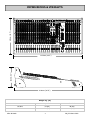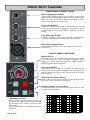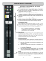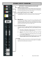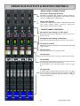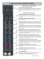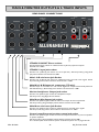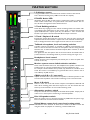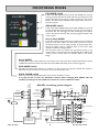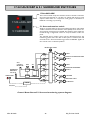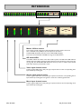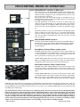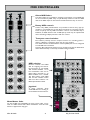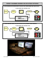
1
USER GUIDE
Publication AP7784
Limited One Year Manufacturers Warranty
This product is warranted to be free from defects in materials or workmanship for period of one year from the date
of purchase by the original owner.
To ensure a high level of performance and reliability for which this equipment has been designed and manufactured,
read this User Guide before operating.
In the event of a failure, notify and return the defective unit to the place of purchase.
If this is not possible then please contact the authorised ALLEN & HEATH distributor or agent in your country as
soon as possible for repair under warranty subject to the following conditions.
Conditions of Warranty
The equipment has been installed and operated in accordance with the instructions in this User Guide.
The equipment has not been subject to misuse either intended or accidental, neglect, or alteration other than as
described in the User Guide or Service Manual, or approved by ALLEN & HEATH.
Any necessary adjustment, alteration or repair has been carried out by an authorised ALLEN & HEATH distributor or
agent.
This warranty does not cover fader wear and tear.
The defective unit is to be returned carriage prepaid to the place of purchase, an authorised ALLEN & HEATH distributor or agent with proof of purchase.
Please discuss this with the distributor or the agent before shipping.
If the unit is to be repaired in a different country to that of its purchase the repair may take longer than normal,
whilst the warranty is confirmed and parts are sourced.
Units returned should be packed to avoid transit damage.
In certain territories the terms may vary. Check with your ALLEN & HEATH distributor or agent for any additional
warranty which may apply.
If further assistance is required please contact Allen & Heath Ltd.
IMPORTANT- PLEASE READ CAREFULLY:
By using this Allen & Heath product and the software within it, you agree to be bound by the terms
of the relevant End User Licence Agreement (EULA), a copy of which can be found on the Allen & Heath
website in the product's pages. You agree to be bound by the terms of the EULA by installing, copying,
or otherwise using the software.
This product complies with the European Electromagnetic Compatibility directive 2004/108/EC
and the European Low Voltage Directive 2006/95/EC.
This product has been tested to EN55103 Parts 1 & 2 1996 for use in Environments E1, E2, E3, and E4 to
demonstrate compliance with the protection requirements in the European EMC directive 2004/108/EC.
During some tests the specified performance figures of the product were affected. This is considered
permissible and the product has been passed as acceptable for its intended use. Allen & Heath has a strict
policy of ensuring all products are tested to the latest safety and EMC standards. Customers requiring more
information about EMC and safety issues can contact Allen & Heath.
NOTE: Any changes or modifications to the console not approved by Allen & Heath could
void the compliance of the console and therefore the users authority to operate it.
GS-R24 User Guide AP7784 Issue 1
Copyright © 2010 Allen & Heath Limited. All rights reserved
Allen & Heath Limited
Kernick Industrial Estate, Penryn, Cornwall, TR10 9LU, UK
http://www.allen-heath.com
Allen & Heath
3
GS_R24 User Guide
PACKED ITEMS
Check that you have received the following:
0
20
30
0
20
40
GAIN
30
0
20
40
GAIN
50
30
0
20
40
GAIN
50
30
0
20
40
GAIN
50
30
0
20
40
GAIN
50
30
0
20
40
GAIN
50
30
0
20
40
GAIN
50
30
0
20
40
GAIN
50
30
0
20
40
GAIN
50
30
0
20
40
GAIN
50
30
30
0
20
40
GAIN
50
0
20
40
GAIN
50
30
0
20
40
GAIN
50
30
0
20
40
GAIN
50
30
0
20
40
GAIN
50
30
ST1
-10
LEV
40
GAIN
50
ST3
-5
6
60 40
-14
+48V
HPF
POL
100Hz
HF
6
60 40
-14
+48V
LINE
HPF
POL
100Hz
HF
6
60 40
-14
+48V
LINE
HPF
POL
100Hz
HF
6
60 40
-14
+48V
LINE
HPF
POL
100Hz
HF
6
60 40
-14
+48V
LINE
HPF
POL
100Hz
HF
6
60 40
-14
+48V
LINE
HPF
POL
100Hz
HF
6
60 40
-14
+48V
LINE
HPF
POL
100Hz
HF
6
60 40
-14
+48V
LINE
HPF
POL
100Hz
HF
6
60 40
-14
+48V
LINE
HPF
POL
100Hz
HF
6
60 40
-14
+48V
LINE
HPF
POL
100Hz
HF
6
60 40
-14
+48V
LINE
HPF
POL
100Hz
HF
6
60 40
-14
+48V
LINE
HPF
POL
100Hz
HF
6
60 40
-14
+48V
LINE
HPF
POL
100Hz
HF
6
60 40
-14
+48V
LINE
HPF
POL
100Hz
HF
6
60 40
-14
+48V
LINE
HPF
POL
100Hz
HF
6
60 40
-10
LEV
0
-20
50
INST
+48V
POL
BOOST
INST
To LR
To CH
HPF
POL
12k
-15
-15
Q
-15
4k
4k
700
HM
-15
4k
700
HM
-15
4k
700
HM
-15
4k
700
HM
-15
4k
700
HM
-15
4k
700
HM
-15
4k
700
HM
-15
4k
700
HM
-15
4k
700
HM
-15
4k
700
HM
-15
To LR
To CH
30
0
20
HF
4k
700
HM
-15
4k
700
HM
-15
4k
700
HM
-15
LEV
6
700
HM
1 +15
-15
Q
G
600
18Hz
G
-15
+15
LF
80Hz
-15
+15
LF
+15
-15
+15
LF
+15
+15
-15
+15
LF
600
+15
600
18Hz
+15
LF
+15
LF
80Hz
-15
+15
+15
LF
+15
+15
LF
+15
+15
LF
+15
+15
LF
+15
+15
LF
+15
+15
LF
+15
+15
LF
+15
-15
+15
LF
+15
+15
LF
+15
300
-15
+15
+15
-15
+15
Valve
Channel 1
-15
+15
-15
+15
EQ IN
EQ IN
AUX
1
LF
80Hz
80Hz
+15
2
2
2
2
2
2
2
2
2
2
+6
2
+6
AUX
2
+6
AUX
+6
-15
2
2
2
EQ IN
-10
-5
2
LEV
0
+6
+6
AUX
3
L
Pre
Pre
AUX
Pre
AUX
5
Pre
AUX
5
Pre
AUX
5
Pre
AUX
5
Pre
AUX
5
Pre
AUX
5
Pre
AUX
R
L
5
5
5
5
5
Pre
AUX
5
5
5
5
AUX1
L-R
1-2
+6
+6
AUX
+6
AUX
6
R
R
R
R
R
R
R
R
R
R
R
M
-10
R
L
R
R
L
R
R
M
L-R
M
L-R
M
L-R
M
L-R
M
L-R
M
L-R
M
L-R
M
L-R
M
L-R
M
L-R
M
L-R
M
L-R
M
L-R
M
L-R
M
L-R
M
L-R
3-4
1-2
3-4
1-2
3-4
1-2
3-4
1-2
3-4
1-2
3-4
1-2
3-4
1-2
3-4
1-2
3-4
1-2
3-4
1-2
3-4
1-2
3-4
1-2
3-4
1-2
3-4
1-2
3-4
1-2
3-4
1-2
A
C
A
C
A
C
A
C
A
C
A
C
A
C
A
C
A
C
A
C
A
C
A
C
A
C
A
C
A
C
A
C
L-R
BUS
B
BUS
DAW
D
B
MUTE
BUS
DAW
D
B
MUTE
SOLO/
SELECT
BUS
DAW
D
B
MUTE
SOLO/
SELECT
BUS
DAW
D
B
DAW
MUTE
SOLO/
SELECT
BUS
D
B
MUTE
SOLO/
SELECT
BUS
DAW
D
B
MUTE
SOLO/
SELECT
BUS
DAW
D
B
MUTE
SOLO/
SELECT
BUS
DAW
D
B
MUTE
SOLO/
SELECT
BUS
DAW
D
B
MUTE
SOLO/
SELECT
BUS
DAW
D
B
MUTE
SOLO/
SELECT
BUS
DAW
D
B
MUTE
SOLO/
SELECT
BUS
DAW
D
B
MUTE
SOLO/
SELECT
BUS
DAW
D
B
MUTE
SOLO/
SELECT
BUS
R
L
DAW
D
B
MUTE
SOLO/
SELECT
DAW
D
B
MUTE
SOLO/
SELECT
L-R
1-2
DAW
R
-10
SOLO/
SELECT
HF
HF
12k
-15
-15
4k
700
HM
1 +15
4k
700
HM
-15
1 +15
4k
700
HM
-15
1 +15
4k
700
HM
1 +15
4k
700
HM
1 +15
0.8 2k
1 +15
4k
700
HM
6k
18k
400Hz
G
-15
1 +15
-15
Q
Q
0.8 120
6
60
600
18Hz
G
600
18Hz
G
600
18Hz
G
600
1 +15
G
0.8 120
6
60
F
300
600
18Hz
Q
0.8 120
6
30
LM
1k
18Hz
60
F
300
30
LM
1k
Q
0.8 120
6
60
F
300
30
LM
1k
Q
0.8 120
6
60
F
300
30
LM
1k
Q
0.8 120
6
60
F
300
30
LM
1k
Q
0.8 120
6
60
F
300
600
18Hz
G
600
18Hz
6
60
F
300
30
LM
1k
300
30
LM
1k
G
600
18Hz
1k
-15
+15
G
-15
LF
AFL
AFL
AFL
L-R
L-R
M
M
M
=
=
PAN
L
DAW
I/P=DAW
MUTE
MUTE
R
L
R
L
R
L
PK!
+6
0
SIG
PK!
+6
0
SIG
PK!
+6
0
SIG
1
1
1
1
MUTE
MUTE
MUTE
MUTE
AFL
AFL
AFL
AFL
0
+15
LF
-15
+15
+15
-15
+15
-15
+15
+15
-15
EQ IN
1
+6
+6
+6
AUX
2
+6
0
+6
AUX
2
2
Pre
Pre
5
5
5
MIN
MAX
17-24=AUX+GRP
5.1 SURROUND
ROUTING KEY:
A: DAW SEND = PRE INS / POST EQ
B: INS SOURCE = MICLINE / DAW
C: FDR SOURCE = MICLINE / DAW
READ
MONO CH
MIDI ENABLED
WRITE
MONO O/P
R
5
GTS
STOP
PLAY
GTE
R
R
R
AUX
6
6
+6
+6
PAN
L
R
+6
AUX
6
+6
PAN
L
+6
AUX
6
+6
PAN
L
+6
AUX
6
+6
PAN
L
+6
PAN
L
R
PAN
L
R
L
M
L-R
M
L-R
M
L-R
M
L-R
M
L-R
M
L-R
M
L-R
3-4
1-2
3-4
1-2
3-4
1-2
3-4
1-2
3-4
1-2
3-4
1-2
3-4
1-2
A
C
A
C
A
C
A
C
A
C
A
C
A
C
A
D
B
D
B
D
B
D
B
D
B
D
B
D
B
BUS
BUS
DAW
MUTE
MIDI FADER MODE
5
+6
AUX
6
+6
PAN
L-R
B
GS-R24
MOTOR FADERS
AUX
1-2
D: FADER = ACTIVE / BYPASS
GS-R24M
Pre
AUX
5
+6
AUX
6
+6
L
L-R
SOLO
CLEAR
+6
Pre
AUX
5
+6
AUX
6
DIG
MASTER
INPUT
ADD MODE
5
4
+6
Pre
AUX
+6
AUX
4
+6
Pre
AUX
+6
AUX
PAN
DIM L-R
SPKRS
SIP
Pre
AUX
+6
AUX
4
+6
MAX
MONO L-R
AFL
Pre
AUX
+6
3
+6
AUX
4
+6
AUX
3
+6
AUX
4
+6
AUX
3
+6
AUX
4
+6
+6
AUX
3
+6
AUX
4
+6
AUX
3
+6
AUX
+6
+6
AUX
3
+6
AUX
+6
AUX
3
4
CRM
LEVEL
L-R/5.1
+6
AUX
AUX
REC
BUS
DAW
MUTE
SOLO/
SELECT
OFF = NO FADER MIDI
BUS
DAW
MUTE
SOLO/
SELECT
BUS
DAW
DAW
MUTE
SOLO/
SELECT
BUS
MUTE
SOLO/
SELECT
BUS
DAW
MUTE
SOLO/
SELECT
DAW
MUTE
SOLO/
SELECT
SOLO/
SELECT
SHIFT
10
10
10
10
10
10
10
10
10
10
10
10
10
10
10
10
10
10
10
10
10
10
10
10
10
10
10
10
0
0
0
0
0
0
0
0
0
0
0
0
0
0
0
0
0
0
0
0
0
0
0
0
0
0
0
0
0
0
0
0
0
10
10
10
10
10
10
10
10
10
10
10
10
10
10
10
10
10
10
10
10
10
10
10
10
10
10
10
10
10
10
10
10
10
20
20
20
20
20
20
20
20
20
20
20
20
20
20
20
20
20
20
20
20
20
20
20
20
20
20
20
20
20
20
20
20
20
30
30
30
30
30
30
30
30
30
30
30
30
30
30
30
30
30
30
30
30
30
30
30
30
30
30
30
30
30
30
30
30
30
40
40
40
40
40
40
40
40
40
40
40
40
40
40
40
40
40
40
40
40
40
40
40
40
40
40
40
40
40
40
40
40
40
Safety Instructions—English
•
Safety Instructions—French
•
Addendum note ROHS
•
Sticker
•
This User Guide
PACKED SEPARATELY ARE THE POWER SUPPLY AND INTERFACE MODULE
4
GS_R24 User Guide
C
D
SOLO/
SELECT
10
Also Packed in the box
M
3-4
DAW
MUTE
10
GS-R24 MIXER
R
BUS
10
•
+15
EQ IN
AUX
1
AUX
2
LF
AUX
+6
AUX
+15
80Hz
-15
EQ IN
1
+6
2
LF
AUX
1
AUX
+15
80Hz
-15
EQ IN
AUX
1
2
LF
80Hz
-15
EQ IN
AUX
+6
2
+15
80Hz
-15
EQ IN
AUX
+6
SOLO MODE
SOLO/
SELECT
-15
80Hz
-15
1
+6
3
MAIN MIX L-R
AFL MODE
R
PK!
+6
0
SIG
LF
AUX
AUX
AUX
2 TRACK 2
PFL MODE
PAN
+15
EQ IN
2
+15
2 TRACK 1
OFF = SEL MODE
=
PAN
-15
80Hz
-15
1
5
+6
AFL
L-R
M
LF
AUX
+6
AUX6
0
+6
+15
80Hz
+15
AUX
AFL
AUX5
0
+6
-15
EQ IN
MAX
M
3-4
I/P=DAW
SOLO/
SELECT
+15
10
Allen & Heath
6
1k
F
6k
18k
400Hz
G
-15
100Hz
1 +15
Q
4k
700
HM
HPF
-15
6
1k
F
6k
18k
400Hz
G
-15
1 +15
0.8 2k
6
1k
F
6k
18k
400Hz
G
-15
-15
Q
0.8 2k
6
1k
F
6k
18k
400Hz
G
+48V
12k
1 +15
Q
0.8 2k
6
1k
F
6k
18k
400Hz
G
-15
50
60 40
HF
12k
1 +15
Q
0.8 2k
6
1k
F
6k
18k
400Hz
G
-15
100Hz
HF
12k
1 +15
Q
0.8 2k
6
1k
F
6k
-15
100Hz
HF
12k
1 +15
Q
0.8 2k
4k
18k
100Hz
HF
12k
1 +15
Q
6
1k
100Hz
HF
12k
1 +15
400Hz
-15
0
10
AFL
L-R
=
SEND=
POST EQ
DAW
D
POL
ALT SPKRS
BUS
SEND=
POST EQ
MUTE
SOLO/
SELECT
M
3-4
BUS
BUS
HPF
1
MIN
-30
10
AUX4
0
+6
AFL
PAN
1-2
POL
AUX
-5
-20
5
-30
+6
BAL
L
HPF
+6
6
+6
BAL
L
POL
TO AUX 3 & 4
AUX
6
+6
PAN
HPF
+6
AUX
6
+6
PAN
L
+6
AUX
6
+6
PAN
POL
LF
O
M
LEV
0
-20
3-4
AUX3
AUX2
+6
5
+6
AUX
6
+6
PAN
L
+6
AUX
6
+6
PAN
L
+6
AUX
6
+6
PAN
L
+6
AUX
6
+6
PAN
L
+6
AUX
6
+6
PAN
L
+6
AUX
6
+6
PAN
L
+6
AUX
6
+6
PAN
L
+6
AUX
6
+6
PAN
L
+6
AUX
6
+6
PAN
L
+6
AUX
6
+6
PAN
L
+6
AUX
6
+6
PAN
L
+6
AUX
6
+6
PAN
L
+6
AUX
6
+6
O
TO AUX 1 & 2
MIN
PAN
HPF
G
+6
-5
AFL
0
AUX
5
POL
100Hz
40
6
MAX
MONO
Pre
AUX
5
M
3-4
AFL
+6
Pre
AUX
-14
HPF
100Hz
30
GAIN
50
60 40
POL
F
+6
4
+6
Pre
AUX
0
20
40
6
HPF
DIG MASTER
AUX
4
+6
Pre
AUX
+6
AUX
4
+6
-14
POL
100Hz
700
+6
+6
R
BUS
1-2
3
+6
AUX
4
+6
Pre
AUX
+6
AUX
4
+6
Pre
AUX
+6
AUX
4
+6
Pre
AUX
+6
AUX
4
+6
Pre
AUX
+6
AUX
4
+6
30
GAIN
50
60 40
HPF
TO GROUPS
LEV
AUX
3
0
20
40
6
POL
Q
L-R
+6
M
BUS
+6
AUX
3
-14
LINE
LM
5
+6
+6
AUX
3
30
GAIN
50
60 40
+48V
TALK
Stereo
L-R
0
10
PAN
2
+6
AUX
3
0
20
40
6
LINE
PHONES
LEVEL
AUX
2
+6
AUX
3
+6
AUX
4
+6
+6
AUX
3
+6
AUX
4
+6
+6
AUX
3
+6
AUX
4
+6
+6
AUX
3
+6
AUX
4
+6
+6
AUX
3
+6
AUX
4
+6
+6
AUX
3
+6
AUX
4
+6
+6
AUX
3
+6
AUX
4
+6
+6
AUX
3
+6
AUX
4
+6
+6
AUX
3
+6
AUX
4
+6
+6
AUX
3
+6
AUX
4
+6
AUX
3
+6
AUX
+6
AUX
3
-14
+48V
80Hz
-5
-30
10
L-R
+6
AUX
-10
-20
5
-30
PAN
+6
AUX
30
GAIN
50
60 40
LINE
G
+6
Stereo
+15
LEV
AUX
0
20
40
6
TO STUDIO
1
+6
AUX
MIN
-14
+48V
HM
+6
Grp
3-4
30
GAIN
50
60 40
LINE
-15
Grp
1-2
0
20
40
6
+48V
0.8 120
AUX
1
2
-14
LINE
Q
MIDI
127
30
GAIN
50
60 40
+48V
30
EQ IN
AUX
1
1
127
TALK
LEV
0
20
40
6
LINE
0.8 2k
MIDI
2 TRACK 1
REPLACE L-R
Stereo
Grp
3-4
+15
AUX
1
Grp
1-2
+6
-14
+48V
Stereo
Stereo
+15
EQ IN
AUX
1
+6
AUX
EQ IN
AUX
1
+6
AUX
EQ IN
AUX
1
+6
AUX
EQ IN
AUX
1
+6
AUX
EQ IN
AUX
1
+6
AUX
EQ IN
AUX
1
+6
AUX
EQ IN
AUX
1
+6
AUX
EQ IN
AUX
1
+6
AUX
EQ IN
AUX
1
+6
AUX
EQ IN
AUX
1
+6
AUX
EQ IN
AUX
1
+6
AUX
EQ IN
AUX
1
+6
AUX
EQ IN
AUX
1
Valve
Channel 2
60 40
LINE
F
1 TO 2
+6
Stereo
PHONES
30
GAIN
50
-15
2 TO 1
2 TRACK DUB
Aux
4/6
0
20
40
6
+48V
R
+15
LM
LF
Aux
3/5
+6
Aux
4/6
+6
-14
12k
L
MAX
Drive
-20
EQ IN
AUX
MIN
250Hz
-15
-15
MAX
30
GAIN
LINE
HF
PFL/AFL ACTIVE
Aux
3/5
2k5
-15
LM
250Hz
1k
+6
5-6
0
HM
6
600
18Hz
80Hz
-15
-15
Aux 2
+6
60 40
10
Drive
+15
HM
G
-15
6
5
OO
HF
12k
2k5
0.8 120
30
80Hz
-15
1 +15
60
F
LM
1k
Aux 2
40
50
-14
+6
Q
600
18Hz
G
80Hz
-15
-15
300
30
LM
1k
30
0
20
+6
5-6
-30
10
HF
12k
ALLEN&HEATH
+16
+9
+6
+3
0
-3
-6
-9
-12
-16
-20
-30
Aux 1
+6
GAIN
60 40
STUDIO 2
Aux 1
-5
-20
5
OO
6
MIN
6
60
F
300
600
18Hz
G
-15
1 +15
0.8 120
6
30
LM
1k
80Hz
-15
-15
Q
0.8 120
60
F
600
18Hz
G
-15
1 +15
Q
300
30
LM
1k
80Hz
-15
-15
6
60
F
300
600
18Hz
G
-15
1 +15
0.8 120
6
30
LM
1k
80Hz
-15
-15
Q
0.8 120
60
F
600
18Hz
G
-15
1 +15
Q
300
30
LM
1k
80Hz
-15
-15
6
60
F
300
600
18Hz
G
-15
1 +15
0.8 120
6
30
LM
1k
80Hz
-15
-15
Q
0.8 120
60
F
600
18Hz
G
-15
1 +15
Q
300
30
LM
1k
80Hz
-15
-15
6
60
F
300
600
18Hz
G
-15
1 +15
0.8 120
6
30
LM
1k
80Hz
-15
-15
Q
0.8 120
60
F
600
18Hz
G
-15
1 +15
Q
300
30
LM
1k
G
-15
-15
6
60
F
300
30
LM
1 +15
0.8 120
6
60
F
300
1k
18Hz
80Hz
-15
-15
Q
0.8 120
6
30
G
-15
1 +15
Q
0.8 120
60
F
LM
1k
80Hz
-15
1 +15
Q
300
600
18Hz
G
80Hz
-15
-15
6
30
LM
1k
G
80Hz
-15
600
18Hz
60
F
300
30
LM
1k
1 +15
0.8 120
6
60
F
300
30
LM
1k
-15
Q
0.8 120
6
60
F
300
600
18Hz
1 +15
Q
0.8 120
6
30
LF
-15
Q
0.8 120
60
F
LM
1 +15
STUDIO 1
6k
18k
400Hz
G
-15
-15
LEV
0
-30
4k
1k
F
6k
18k
400Hz
G
ST4 -10
-5
-20
0.8 2k
4k
700
HM
POL
BOOST
INST
50
-14
ST2 -10
6
1k
F
6k
18k
400Hz
G
+48V
40
SIP SAFE
1 +15
Q
0.8 2k
6
1k
F
6k
18k
400Hz
G
1 +15
Q
0.8 2k
6
1k
F
6k
18k
400Hz
G
SIP SAFE
12k
1 +15
Q
0.8 2k
6
1k
F
6k
18k
400Hz
G
12k
1 +15
Q
0.8 2k
6
1k
F
6k
18k
400Hz
G
12k
1 +15
Q
0.8 2k
6
1k
F
6k
18k
400Hz
G
12k
1 +15
Q
0.8 2k
6
1k
F
6k
18k
400Hz
G
12k
1 +15
Q
0.8 2k
6
1k
F
6k
18k
400Hz
G
12k
1 +15
Q
0.8 2k
6
1k
F
6k
18k
400Hz
G
12k
1 +15
Q
0.8 2k
6
1k
F
6k
18k
400Hz
G
12k
1 +15
Q
0.8 2k
6
1k
F
6k
18k
400Hz
G
12k
1 +15
Q
0.8 2k
6
1k
F
6k
18k
400Hz
G
12k
1 +15
Q
0.8 2k
6
1k
F
6k
18k
400Hz
G
12k
1 +15
Q
0.8 2k
6
1k
F
6k
18k
400Hz
12k
1 +15
Q
0.8 2k
6
700
G
12k
1 +15
Q
0.8 2k
1k
F
HM
12k
1 +15
INST
100Hz
GAIN
12k
I/P = DAW
I/P = DAW
5
10
OO
+48V
LINE
0
20
POWER
0
-30
10
OO
-5
-20
5
-30
-14
LINE
10
CONTENTS
Thank you for purchasing your Allen & Heath GS-R24. To ensure that you get the
maximum benefit from the unit please spare a few minutes familiarizing yourself with the
controls and setup procedures outlined in this user guide. For further information please
refer to the additional information available on our web site, or contact our technical
support team.
http://www.allen-heath.com
This User Guide does not cover the interface modules available for the GS-R24.
The varied modules will have their own User Guide and details of software
drivers, digital connectivity and computer related issues. Also see the website
for details.
Allen & Heath
Warranty ...........................................................
3
Packed Items .....................................................
4
Contents ............................................................
5
Introduction to GS-R24 .......................................
6
Dimensions & Weights ........................................
7
Specifications .....................................................
8
Block Diagram....................................................
10
Mono Input Channel ...........................................
11
Stereo Input Channel..........................................
16
Valve Input Channel ...........................................
20
Aux Masters .......................................................
22
Groups...............................................................
23
Studio Outputs ...................................................
24
Main 2 Track Input & Output connectors..............
25
Master Section ...................................................
26
Monitoring modes...............................................
27
17-24 = Aux/Grp & 5.1 Surround switches ...........
28
Meterbridge .......................................................
29
MIDI Control—Modes of Operation ......................
30
Fader Touch Sensors ..........................................
30
MIDI Controllers .................................................
31
MIDI Implementation .........................................
32
Power Up Configuration Modes............................
35
Connection Diagram (Basic) ................................
36
Mono Input Channel Workflow Options ................
37
Internally set Option Jumper Links ......................
40
Wiring diagrams for audio leads…….....................
41
Product Support .................................................
42
5
GS_R24 User Guide
INTRODUCTION TO THE GS-R24
A Technical Overview:
The Allen & Heath GS-R24 mixer has been carefully and lovingly designed in the beautiful county of Cornwall in the UK and is
manufactured alongside a wide range of professional audio mixing consoles.
Allen & Heath has a long history of making classic recording mixers such as the Sigma, Syncon, System 8, Saber and the
GS3000, but for a few years have concentrated on the live sound, installation and pro DJ markets. The GS-R24 resurrects the
GS product line and stands as a classic recording console for the modern age of Digital Audio Workstation software.
We spent a long time examining how modern recording methods, equipment and software applications have changed the way
musicians and sound engineers work and listening to ideas and requests on forums such as Gearslutz, we have created a product which offers more than a sum of its parts—a combination of not just different technology, but different methods and philosophies.
GS-R24 is designed to fulfil the needs of musicians, sound engineers and producers and is adaptable to different workflow
methods. Briefly, some of the capabilities of the GS-R24 include:
•
Multi-track recording to the digital domain with easy interfacing to a computer DAW with zero latency monitoring of
live sources.
•
Multi-track recording to the digital domain with monitoring sourced from the recorded track in the DAW.
•
Over-dubbing a recorded track whilst monitoring the track and/or live source.
•
Multi-track mixdown using state-of-the-art analogue summing techniques.
•
Multi-track mixing performed in the DAW using the GS-R24 as a controller.
•
Patching, routing and monitoring a comprehensive matrix of signals in a studio environment—artists monitors, effects
processors, external devices and studio control room monitors.
•
Surround sound mixes can be created in a DAW and conveniently monitored through a single level control.
•
Automating a mix using the motorised faders on GSR-24M to either create an automated mix in the digital domain or
create an automated analogue summing mix using the faders for channel level control as well as parameter control.
Our claim that the GS-R24 is a modern classic recording console is not without foundation. It is a progression of our in-line
recording mixers, many regarded as “classics” but with interfacing to each channel provided by a Digital Audio Workstation.
Actually, the GS-R24 isn’t just designed for modern times—it is built with the future in mind, with the interfacing hardware
housed in a removable module which can be swapped and updated over time. This means that you won’t have to change your
lovely console when you need to upgrade your digital interfacing technology years from now.
The GS-R24 is built utilising individual vertically mounted channel circuit boards with each rotary control fixed with a metal nut
to the front panel. This provides a very robust product that will resist damage and give years of reliable use. It also makes servicing easier should it be required. The motor fader system can be removed separately to the rest of the system and faders
can be changed individually if the are damaged (from top impact for example).
Mic/Line Pre-amps:
The ultimate performing pre-amps are fitted to GS-R24. Similar in topology to those used in the renowned ZED-R16, they
comprise a symmetrical circuit with individual linearising feedback to both phases, along with the lowest noise transistors available, providing very low distortion over a wide bandwidth and extremely low noise which translates to superior clarity and
dynamic range.
EQ:
Extremely powerful, flexible and fully implemented mono channel EQ. Parametric mid sections with extended frequency range
and controllable Q- factor allow a huge range of corrective and creative possibilities.
MIDI Control:
We have developed the control aspect on GS-R24 to give an intuitive, flexible, easy way to control multiple parameters in a
variety of DAWs. Each of the mono channel faders has MIDI capability and are motorised on GS-R24M. In addition there is a
MIDI Select switch on each channel and in the MIDI controller section 2 x 60mm faders, 12 x rotaries, 14 switches plus transport controls and a jogwheel.
Interface Modules:
The interface module fits in the rear panel of the console. It handles 32 channels in and 32 channels out plus the control protocol. This manual does not cover the details of the modules as the variety of modules available will change in the future. Please
consult the A&H website for details and the User Guide for the individual modules.
Allen & Heath
6
GS_R24 User Guide
613mm (24.1”)
DIMENSIONS & WEIGHTS
192mm (7.5”)
1125mm (44.3”)
97
.0
0°
616mm (24.25”)
Weight kg (lb)
Allen & Heath
Unpacked
Packed
GS-R24
30 (66)
38 (84)
GS-R24M
38 (84)
40 (88)
7
GS_R24 User Guide
GS-R24 SPECIFICATIONS
Operating Levels
Inputs
Mono channel (XLR) Input
-6 to –60dBu for nominal (+14dBu in max)
Mono channel Line Input (Jack socket)
+14 to –40dBu (+34dBu maximum)
Insert point (TRS Jack socket)
0dBu nominal +21dBu maximum
Stereo Input (Jack sockets)
0dBu nominal (control = Off to +10dB)
Stereo input (phono sockets)
0dBu nominal (control = Off to +15dB)
Valve channel (XLR)
-10 to –60dBu for nominal (+10dBu max)
Valve channel (Line)
+10 to –40dBu for nominal (+30dBu maximum)
Valve channel (Inst gain boosted)
-16 to –66dBu for nominal (122mV to 0.388mV rms)
2 Track Input (phono or TRS jack sockets)
0dBu nominal +21dBu maximum
Outputs
Main (2 Track 1) L-R (XLR) & Groups 1-4 (TRS Jack)
+4dBu nominal. +27dBu maximum.
L-R Insert & Group Inserts (TRS Jack socket)
0dBu nominal +21dBu maximum
2 Track 2 Outputs (Jack sockets)
0dBu nominal. +21dBu maximum.
All other analogue outputs
0 nominal +21dBu maximum
Headroom
Analogue headroom from nominal (0Vu)
21dB
Analogue headroom at Mix summing amplifier
23dB
Frequency Response
Mic in to Mix L/R Out, 10dB gain
+/-1dB 10Hz to 130kHz.
Mic in to Mix L/R Out, 30dB gain
+/-0.5dB 20Hz to 80kHz.
Mic in to Mix L/R Out, 50dB gain
+/-1dB 20Hz to 80kHz.
Line in to Mix L/R out 0dB gain
+/-0.5dB 20Hz to 20kHz
Stereo in to Mix L/R out
+/-0.5dB 20Hz to 40kHz
THD+n
Mic in to Mix L/R Out, 10dB gain 1kHz +10dBu out (DC to 22kHz)
0.0015%
Mic in to Mix L/R Out, 30dB gain 1kHz (DC to 22kHz)
0.0025%
Mic in to Mix L/R Out, 50dB gain 1kHz (DC to 22kHz)
0.0035%
Mic in to Mix L/R Out, 30dB gain 10kHz (DC to 30kHz)
0.0025%
Line in to Mix L/R out 0dB gain +10dBu 1kHz (DC to 22kHz)
0.002%
Stereo in to Mix L/R out 0dB gain +10dBu 1kHz (DC to 22kHz)
0.002%
Allen & Heath
8
GS_R24 User Guide
GS-R24 SPECIFICATIONS
Noise
Mono ch Mic Pre EIN @ 60dB gain 150R input Z 22-22kHz
-128.5dBu
Mono ch Mic Pre EIN @ 30dB gain 150R input Z 22-22kHz
-124dBu
Mix Noise, LR out, 0 channels routed, Ref +4dBu, 22-22kHz
-97dB (-93dBu)
Mix Noise, LR out, 12 channels routed, Ref +4dBu, 22-22kHz
-90dB (-86dBu)
Mix Noise, LR out, 24 channels routed, Ref +4dBu, 22-22kHz
-89dB (-85dBu)
Mix Noise, Aux 1-4 out, sends minimum, masters at unity 22-22kHz
-84dBu
Mix Noise, Groups 1-4, 24 channels routed, Ref +4dBu, 22-22kHz
-89dB (-85dBu)
Power consumption Motorised Fader model
170W Nominal 300W Max
Power consumption non-Motorised Fader model
170W
Weight GS-R24 unpacked/packed
30/38kg
Weight GS-R24m unpacked/packed
32/40kg
Allen & Heath
9
GS_R24 User Guide
BLOCK DIAGRAM
MIC IN
LINE IN
+48V
L
R
Line
Invert
GAIN
GAIN
Invert
GAIN
+
-
GAIN
+
-
100Hz
HPF
A
LF
RECORDING
INTERFACE
LM
f
q
DAC
g
g
HF
POST-EQ
HM
f
q
4 BAND PARAMETRIC EQUALISER
g
HF
EQ
IN
C
CHANNEL METER
POST-EQ
PRE-MUTE
FADER OUTPUT
POSTFADER
PRE-MUTE
PRE FADER MONO
CHANNEL
METER
D
FADER
BYPASS
+
POST FADER MONO
FADER
MIDI DATA
TO MIDI CPU
CONTROL
SOLO LOGIC
LOGIC CONTROL
PRE
+
FADER
SOLO/SELECT
SOFT MUTE
MUTE
AUX 5-6 PRE/POST
SELECT
SOLO/SELECT
SOFT MUTE
MUTE
DIGITAL RETURN
POST-EQ
PREFADE
SELECT
+
SOLO LOGIC
LOGIC CONTROL
PRE
AUX 5-6 PRE/POST
SELECT
AUX 1 - 2
AUX 1
AUX 2
AUX 3
AUX 4
AUX 6
AUX 5
+
AUX 1
AUX 2
AUX 3
AUX 4
AUX 5
DIRECT OUT
PAN
PFL
AFL L
AFL R
MONO
L-R
1-2
3-4
3-4
1-2
L-R
MONO
MIDI SELECT
BAL
PFL
AFL L
AFL R
3-4
1-2
L-R
MONO
MIDI SELECT
PAN
AFL L
AFL R
GROUPS
AUX 6
AUX 3 - 4
TALK TO STUDIO
AUX 1
AUX 2
AUX 3
AUX 4
AUX 5
AUX 6
PFL
R
L
+
-
+
-
2 TRACK 1
REPLACE L-R
LEVEL
DIGITAL MASTER
L
R
2 TRK 1 IN
2 TRK 2 IN
AUX 1 AUX 2
2 TRACK 1 IN
2 TRACK 2 IN
DIGITAL MASTER IN
L-R POSTFADE
MONO POSTFADE
SOLO-IN-PLACE
TALK TO
STUDIO
ADD
AFL
PFL
SOLO MODE
AFL L
AFL R
LOGIC CONTROL FOR
SOLO MODES & MIDI
ADC
L INSERT
TIP SEND
TIP SEND
R INSERT
TIP SEND
MONO INSERT
TIP SEND
GROUP INSERT
AFL
AFL
RECORDING
INTERFACE
+10dB
MAIN LR
DAC
MUTE
L-R POSTFADE
MONO
+10dB
+10dB
GROUP 1
+6dB
AUX 1
L-R
DUB 2-1
L-R
MONO
GROUP METER
LEVEL
PHONES
LEVEL
VU
COPY FOR 2-6
R
STUDIO OUT R
STUDIO OUT L
AUX1 OUT
COPY FOR 2-6
GROUP 1 OUT
MONO OUT
2TRK 2 OUT
RIGHT
MAIN (2TRK 1) OUT
LEFT
BALANCED
+4dBu NOMINAL
L
RIGHT
LEFT
UNBALANCED
-2dBu NOMINAL
VU
MAIN MIX L-R VU METERS
DIGITAL MASTER IN
DUBBING
DUB 1-2
MONO
AFL
M
+
MONITORS LEVEL
LEFT
SUB BASS
SURROUND ONLY
CENTRE
RIGHT
ALTERNATE SPEAKERS
LEFT
RIGHT
CONTROL ROOM MONITORS
STUDIO OUT
L-R POSTFADE M POSTFADE
ALT
PFL
STEREO
GRP 3-4
GRP 2
-20dB
-20dB
DIM
AFL
STEREO
GRP 1-2
STEREO
SURROUND
INTERFACE I/P CH 25-30
AUX 3
AUX 5
ADC
DIGITAL RETURN
PRE-INSERT
INSERT
g
HMF
g
METER BAR
EQ
IN
MONO CHANNEL
DAC
LMF
g
RECORDING
INTERFACE
LF
g
4 BAND EQUALISER
g
DAC
DRIVE
BLEND
LEVEL
DIRECT OUT
STUDIO
MIDI FADERS + ROTARIES + SWITCHES
MIDI CONTROLLER PROCESSOR
TALK
POSTFADER
MAIN MIX L
MAIN MIX R
MONO MIX
GROUP 1
GROUP 2
GROUP 3
GROUP 4
DIGITAL SEND
POST-EQ
B
ADC
RECORDING
INTERFACE
VALVE
STAGE
SOLID
STATE
STAGE
METER LED
INSERT
STEREO CHANNEL
SOURCE = DAW
DIGITAL SEND
POST-EQ
A
MIX L
MIX R
+
ADC
+
SOURCE = DAW
VALVE CHANNEL
GAIN
TALKBACK
TALKBACK
MIC
FADER OUTPUT
PHANTOM POWER SWITCH
ST1 & 2 RCA
L
R
+48V
HI-Z DI
CLASS A
FET
Line
PHANTOM POWER SWITCH
ST1 & 2 JACK
MIC IN
Hi Z
INSTRUMENT
/LINE LEVEL
GAIN BOOST
CHANNEL 1
17-24 = AUX-GROUP
CHANNEL 8
STEREO 1 L
STEREO 1 R
STEREO 2 L
STEREO 2 R
VALVE 1
VALVE 2
MASTER L
MASTER R
CHANNEL 24
CHANNEL 17
CHANNEL 16
CHANNEL 9
CHANNEL 1
RECORDING
INTERFACE
MIDI
INTERFACE
CHANNEL 8
CHANNEL 9
CHANNEL 16
CHANNEL 17
AUX 1
CHANNEL 18
AUX 2
CHANNEL 19
AUX 3
CHANNEL 20
AUX 4
CHANNEL 21
GROUP 1
CHANNEL 22
GROUP 2
CHANNEL 23
GROUP 3
CHANNEL 24
GROUP 4
STEREO 1 L
STEREO 1 R
STEREO 2 L
STEREO 2 R
VALVE 1
VALVE 2
MASTER L
MASTER R
AUX 4
AUX 6
GS_R24 User Guide
10
Allen & Heath
PRE FADER
PRE FADER MONO
POST FADER
POST FADER MONO
MONO INPUT CHANNEL
CT
REAR PANEL CONNECTIONS
DIRECT
OUT
RT
Direct Output Jack Socket
Standard 1/4” (6.25mm) Jack socket for Channel output signal.
Wired Tip=Hot(+), Ring=Cold(0V), Sleeve=Chassis. Nominal level is
0dBu. The source for the Direct Output is selectable by option
jumpers internally, factory set to Pre-Fade.
Insert Jack Socket
INSERT
Standard 1/4” (6.25mm) Jack socket for unbalanced insert send and
return signals. Wired Tip=send, Ring=return, Sleeve=Chassis. Nominal level is 0dBu. The insert point is after the 100Hz filter and before
the EQ.
Line Input Jack Socket
LINE
Standard 1/4” (6.25mm) Jack socket for balanced or unbalanced line
level signals. Wired Tip=Hot(+), Ring=cold (-), Sleeve=Chassis.
MIC
Microphone Input Socket
Standard 3-Pin XLR socket wired as Pin 1=Chassis, Pin 2=hot (+),
Pin 3=Cold (-).
FRONT PANEL CONTROLS
Gain Control
M1
0
20
GAIN
-14
30
This adjusts the gain of the input amplifier to match the signal level
of the input. The gain is varied from +6dB to +60dB for signals
plugged in to the xlr socket (Mic Input) and –14dB to +40dB for
signals plugged into the Line input jack.
Line Input Switch
40
Selects the source for the pre-amp from XLR to Line input jack. The
balanced input signal is padded by 20dB but noise and distortion are
kept to a minimum in order to make it transparent when connecting
external devices.
50
6
48V Phantom Power Switch
60 40
LINE
Applies +48V to pins 2 and 3 of the XLR input though 6k8 resistors
for phantom powered condenser microphones.
+48V
Polarity (phase) reverse switch
POL
HPF
100Hz
Reverses the polarity of the balanced input signal phases for both
mic XLR and Line jack inputs.
dBr
0.00
-5.00
100Hz Hi-pass Filter
The Hi-pass filter is used for reducing pop noise and
rumble from microphone signals. It is a 2-pole (12dB
per octave) filter with a corner frequency set at just
below 100Hz.
The filter affects signals from both Mic XLR and Line
jack socket.
-10.00
-15.00
-20.00
-25.00
-30.00
-35.00
-40.00
10.00 Hz
Allen & Heath
11
100.00
1000.00
10000.00
GS_R24 User Guide
40000.00
MONO INPUT CHANNEL
0
20
Pre-Amp performance notes
30
GAIN
-14
The GS-R24 pre-amp is a highly developed and proven design. Originally evolved
from a balanced summing amplifier circuit originally designed back in the late
1980s for the Focusrite Forte console whilst working for industry legend Rupert
Neve. Very low noise transistors are employed in a symmetrical topology with
local phase compensation resulting in an inherently stable but wide bandwidth,
low distortion, very low noise design.
40
50
6
60 40
LINE
+48V
HPF
POL
100Hz
1.00000
THD+n plots of pre-amp
at 10, 20, 30 and 40dB
gain showing uniformity
of distortion performance
over a wide range of gain
settings.
0.10000
0.01000
HF
0.00100
%
0.00010
12k
10.00 Hz
-15
100.00
1000.00
10000.00
1 +15
HF EQ
The HF (High Frequency) equaliser affects the frequency response of the
higher audible frequencies. The corner frequency of 12kHz is around 3dB
from the maximum cut or boost of the circuit.
Q
0.8 2k
1k
F
6
700
HM
dBr
20.00
4k
6k
15.00
10.00
18k
400Hz
5.00
G
0.00
-5.00
-10.00
-15
1 +15
-15.00
-20.00
10.00 Hz
Q
F
0.8 120
60
1000.00
10000.00
40000.00
HMF EQ
6
300
30
LM
100.00
600
The HMF (High Mid Frequency) equaliser affects the upper middle of the
audible frequency range. The frequency graduations on the sweep control are the centre frequencies of the EQ. The Q factor is the width of
the equaliser curve and is variable from a wide 0.8 to a sharp 6.
1k
18Hz
dBr
20.00
G
15.00
10.00
LF
-15
+15
5.00
0.00
-5.00
80Hz
-10.00
-15
+15
-15.00
-20.00
EQ IN
Allen & Heath
10.00 Hz
100.00
12
1000.00
10000.00
GS_R24 User Guide
40000.00
MONO INPUT CHANNEL
LMF EQ
HF
The LMF (Low Mid Frequency) equaliser affects the lower middle of the
audible frequency range. The frequency graduations on the sweep control are the centre frequencies of the EQ. As with the HMF section, the
Q factor is variable from 0.8 to 6. The graph shows the Q setting in the
minimum, and maximum positions, and the extents of the frequency
range.
12k
-15
1 +15
Q
dBr
20.00
0.8 2k
1k
F
6
15.00
4k
700
HM
10.00
6k
5.00
0.00
18k
400Hz
-5.00
-10.00
G
-15.00
-20.00
10.00 Hz
-15
0.8 120
60
6
300
30
LM
1000.00
10000.00
40000.00
LF EQ
Q
F
100.00
1 +15
The LF (Low Frequency) equaliser affects the frequency response of the
lower audible (bass) frequencies. The corner frequency of 60Hz is
around 3dB from the maximum cut or boost of the circuit.
600
dBr
20.00
18Hz
1k
15.00
G
10.00
5.00
0.00
LF
-15
+15
-5.00
-10.00
-15.00
80Hz
-20.00
-15
+15
EQ IN
10.00 Hz
100.00
1000.00
10000.00
40000.00
EQ IN
The EQ IN switch enables the equaliser when pushed in. The EQ is bypassed when the switch is in its up position.
Allen & Heath
13
GS_R24 User Guide
MONO INPUT CHANNEL
Auxiliary sends 1 & 2
AUX
Each of these controls sends a signal to an Aux bus. The signal is sourced prefade which means that the level is independent of, and unaffected by the fader.
Auxes 1 & 2 are primarily used for foldback monitoring purposes, as the fader
does not affect the level.
These sends are affected by the Mute switch by default, so muting the channel
will also mute the Aux sends but they can be selected to be independent of
the mute status.
The control varies the signal level to the bus from off (fully attenuated) to
+6dB, with unity gain at the arrow.
There are master level controls for all of the Auxiliary outputs situated in the
master section of the mixer.
1
+6
AUX
2
+6
AUX
3
Auxes 3 & 4
The source for Aux sends 3 & 4 is normally post-fader but can be selected
pre-fader by pressing the Pre switch.
+6
AUX
4
Auxes 5 & 6
+6
The source for Aux sends 5 & 6 is post-fader by default. They are also muted
by the Mute switch. Auxes 5 & 6 are primarily used for effects sends. However, an internal jumper option can be altered to select them to be sourced
pre-fader, for example if more monitor sends are required.
Pre
AUX
5
PAN
+6
The pan control adjusts how the signal from the mono input channel is shared
between the left and right buses and between odd and even group buses.
AUX
6
Bus Routing Switches
+6
PAN
L
R
M
L-R
BUS
1-2
3-4
A
C
B
DAW
Allen & Heath
The L-R switch connects the post-fade signal to the main L-R mix bus
via the pan control. For minimum noise from the mix bus summing
amplifier, leave the switches in their up positions if the channel signal is
not required on the bus.
The M switch routes the post-fade signal to a mono mix bus which is
independent of the pan control.
The 1-2 and 3-4 switches are for routing the post-pan signal to pairs of
audio sub-groups which have independent insert points, master faders,
outputs and sub routing to the main mix buses if required.
D
14
GS_R24 User Guide
MONO INPUT CHANNEL
A
B
C
DAW
INTERFACE CONFIGURATION SWITCHES
DAW send source switch
D
A
MUTE
SOLO/
SELECT
Switch A determines the source for the interface send for each channel. In
the up position the source is just after the pre-amp and Hi pass filter. If
pressed in, then the source is from after the EQ IN switch. One or the other
signal will always be sent to the interface.
DAW return to channel (Pre Insert) switch
B
Switch B selects the source for the channel to be the interface return, which
is switched in at just before the channel insert point. In other words the preamp signal is replaced by the interface return for that channel just before the
insert point.
DAW return to channel (Post EQ) switch
C
Switch C selects the source for the channel at a point after the EQ. So if
pressed, the channel signal from the EQ is replaced with the interface return
for that channel which then feeds the fader and also the pre-fade sends.
Fader Bypass switch
D
Switch D allows the channel level control element of the fader to be bypassed at unity gain. This is useful when using the fader purely as a MIDI control device when also utilising the channel audio path for mixing or monitoring but not wanting fader movements to affect the channel signal level.
10
For a graphical explanation of the interface
configuration switches, and interface routing
options please refer to page 39.
Mute Switch
0
This mutes or cuts the signal to the mix buses, the post-fade Auxes and the
pre-fade Auxes (where muting is enabled). A rectangular LED illuminates to
show the Mute switch is pressed. The “soft” mute circuit has a time constant
of 30mS for minimum Fourier clicks caused by sharp edges, and can be triggered by soloing another channel in Solo in Place mode.
Solo/Select Switch
10
20
30
40
Allen & Heath
The channel solo/select switch is multi-functional switch that operates as a
channel solo switch or a MIDI select switch to control DAW parameters,
The modes are set by selector switches in the master section and are as follows:
1)
PFL: Sends a pre-fade (also pre-mute) signal from the channel to the
monitoring system.
2)
AFL: Sends an after-fade (also post pan) signal to the monitoring system.
3)
Solo in Place: Any pressed solo switches will mute other mono input
or stereo input channels (unless SiP safed) unless their solo switches
are pressed also (in ADD mode).
4)
Select: The channel monitoring is disabled and the switch sends a MIDI
message. The LED illumination can be tallied internally or can be tallied by the DAW in order to maintain synchronisation of status.
Fader
A 100mm fader controls the level of the channel signal path to mix buses and
post-fade auxes. The mono channel faders can also be used as MIDI controllers for parameters in DAW software. On the GS-R24M the faders are motorised, further information on page 32.
15
GS_R24 User Guide
STEREO INPUT CHANNEL
REAR PANEL CONNECTIONS
ST1 IN
ST1 (& ST3) Phono sockets
Standard RCA phono sockets for unbalanced stereo inputs.
Nominal level = 0dBu
L
R
L/M
ST2
IN
ST2 (& ST4) Jack sockets
Standard 1/4” (6.25mm) Jack socket for balanced or unbalanced line level
signals. Wired Tip=Hot(+), Ring=cold (-), Sleeve=Chassis.
The left channel input is connected to the break contacts of the right channel
input socket so a mono source can feed both left & right channels if required.
Nominal level = 0dBu
R
FRONT PANEL CONTROLS
ST1
LEV
-10
ST1 Level
-5
The input level control varies the level of the signal from off (fully attenuated)
to +10dB of gain at the maximum position.
0
-20
5
-30
10
OO
ST1 input routing switch
To LR
To CH
ST1 (& ST3) can be routed directly to the main L-R mix bus (switch up) or to
the corresponding stereo channel section where the signals will sum with the
ST2 (& ST3) inputs from the jack sockets.
ST Channel SiP Safe switch
SIP SAFE
ST2 -10
LEV
-5
ST2 Level
0
-20
5
-30
OO
Allen & Heath
The Solo in Place Safe switch isolates the stereo channel from the muting
function of the Solo in Place system. Designed so that if effects are returned
to one or both stereo channels, they can be safe from muting by the SiP system thereby allowing any soloed channels to be heard with effects intact.
The input level control varies the level of the signal from off (fully attenuated)
to +10dB of gain at the maximum position.
10
16
GS_R24 User Guide
STEREO INPUT CHANNEL
SIP SAFE
ST2 -10
LEV
-5
With a 3dB corner frequency of 12kHz and maximum cut & boost of 15dB,
the HF EQ is tuned to the upper range of the audio spectrum.
dBr
20.00
0
-20
Stereo HF EQ
15.00
5
-30
OO
10
10.00
5.00
0.00
-5.00
HF
-10.00
-15.00
12k
-20.00
10.00 Hz
-15
100.00
1000.00
10000.00
40000.00
+15
Stereo HM & LM EQ
HM
Fixed bandpass equaliser sections set at 2.5kHz and 250Hz and with a maximum cut & boost of 15dB.
2k5
-15
+15
LM
dBr
20.00
15.00
10.00
250Hz
5.00
0.00
-15
+15
-5.00
LF
-10.00
-15.00
80Hz
-20.00
10.00 Hz
-15
100.00
1000.00
10000.00
40000.00
+15
Stereo LF EQ
EQ IN
A shelving equaliser with a 3dB corner frequency of 60Hz and with a maximum cut & boost of 15dB.
dBr
20.00
15.00
EQ IN
The EQ IN switch enables the equaliser
when pushed in. The EQ is bypassed
when the switch is in its up position.
10.00
5.00
0.00
-5.00
-10.00
-15.00
-20.00
10.00 Hz
Allen & Heath
100.00
17
1000.00
10000.00
GS_R24 User Guide
40000.00
STEREO INPUT CHANNEL
Auxiliary sends 1 & 2
EQ IN
Each of these controls sends a signal to an Aux bus. The signal is sourced prefade which means that the level is independent of, and unaffected by the fader.
Auxes 1 & 2 are mono buses so the stereo pre-fade signals are summed together to provide the source for the send.
These sends are not affected by the Mute switch by default, so muting the
channel does not mute the Aux sends but they can be selected to be postmute where they will follow the mute status (internal jumper links).
The control varies the signal level to the bus from off (fully attenuated) to
+6dB, with unity gain at the arrow.
There are master level controls for all of the Auxiliary outputs situated in the
master section of the mixer.
AUX
1
+6
AUX
2
+6
Auxes 3 & 4
AUX
The source for Aux sends 3 & 4 is normally post-fader but can be selected
pre-fader by pressing the Pre switch.
3
+6
Auxes 5 & 6
AUX
The source for Aux sends 5 & 6 is post-fader by default. They are muted by
the Mute status. Auxes 5 & 6 are primarily used for effects sends. However,
an internal jumper option can be altered to select them to be sourced prefader, for example if more monitor sends are required.
4
+6
Pre
Balance
The balance control adjusts how the stereo left and right channels are balanced when routed to the stereo L-R mix bus or the pairs of group buses.
Unity gain is in the middle, the opposite signal is attenuated when set left or
right.
AUX
5
+6
Bus Routing Switches
+6
The L-R switch connects the post-fade left & right signals to the main
L-R mix bus via the balance control. For minimum noise from the mix
bus summing amplifier, leave the switches in their up positions if the
channel signal is not required on the bus.
The M switch routes the post-fade mono sum of left & right to a mono
mix bus which is independent of the balance control.
The 1-2 and 3-4 switches are for routing the post-balance signal to
pairs of audio sub-groups which have independent insert points, master faders, outputs and sub routing to the main mix buses if required.
AUX
6
BAL
L
R
M
L-R
BUS
1-2
3-4
SEND=
POST EQ
DAW
I/P=DAW
Allen & Heath
18
GS_R24 User Guide
STEREO INPUT CHANNEL
SEND=
POST EQ
DAW
I/P=DAW
MUTE
INTERFACE CONFIGURATION SWITCHES
DAW send source switch
This switch determines the source for the interface send for the stereo channel. In the up position the source is taken from the post-level input signals. If
the switch is pressed then the source is taken from after the stereo EQ. One
or the other signal will always be sent to the interface.
Stereo input channel source = DAW
SOLO/
SELECT
The I/P=DAW switch swaps the source for the stereo channel from the Jack
socket/RCA phono connectors to the interface returns for that channel.
Mute Switch
This mutes or cuts the signal to the mix buses, the post-fade Auxes and the
pre-fade Auxes (where muting is enabled). A rectangular LED illuminates to
show the Mute switch is pressed. The “soft” mute circuit has a time constant
of 30mS for minimum Fourier clicks caused by sharp edges, and can be triggered by soloing another channel in Solo in Place mode.
Solo/Select Switch
10
0
10
The channel solo/select switch is multi-functional switch that operates as a
channel solo switch or a MIDI select switch to control DAW parameters,
The modes are set by selector switches in the master section and are as follows:
1)
PFL: Sends a pre-fade (also pre-mute) mono sum of left & right signals
from the stereo channel to the monitoring system.
2)
AFL: Sends an after-fade (also post Bal) stereo signal to the monitoring
system.
3)
Solo in Place: Any pressed solo switches will mute other mono input
or stereo input channels (unless SiP safed) unless their solo switches
are pressed also (in ADD mode).
4)
Select: The channel monitoring is disabled and the switch sends a MIDI
message. The LED illumination can be tallied internally or can be tallied by the DAW in order to maintain synchronisation of status.
Fader
A 100mm stereo fader controls the level of the left & right channel signals to
mix buses and post-fade auxes. The stereo channel faders are not MIDI enabled and cannot be motorised or automated.
20
30
40
Allen & Heath
19
GS_R24 User Guide
VALVE INPUT CHANNEL
REAR PANEL CONNECTIONS
T
DIRECT
OUT
T
INSERT
Direct Output Jack Socket
Standard 1/4” (6.25mm) Jack socket for Valve channel output signal.
Wired Tip=Hot(+), Ring=Cold(0V), Sleeve=Chassis. Nominal level is
0dBu. The source for the Direct Output is taken from pre the master level control and is impedance balanced which means that the
source resistance to the Tip(+) and Ring(0v) contacts are matched in
order to maintain common-mode interference rejection.
Insert Jack Socket
Standard 1/4” (6.25mm) Jack socket for unbalanced insert send and
return signals. Wired Tip=send, Ring=return, Sleeve=Chassis. Nominal level is 0dBu. The insert point is after the valve pre-amp stage.
LINE/
INST
IN
MIC
Line/Instrument Input Jack Socket
Standard 1/4” (6.25mm) Jack socket. This is an unbalanced input designed so that it can be used for instruments with either line level
(active) outputs or low level magnetic or piezo pickups.
Wired Tip=Hot(+), Ring=cold (0V), Sleeve=Chassis.
Microphone Input Socket
Standard 3-Pin XLR socket wired as Pin 1=Chassis, Pin 2=hot (+),
Pin 3=Cold (-).
FRONT PANEL CONTROLS
I/P=DAW switch
I/P = DAW
INST
+48V
POL
BOOST
INST
0
20
30
40
GAIN
-14
Line/Instrument Input Switch
Selects the source for the pre-amp from XLR to Line/Instrument
input jack. The jack input is extremely high impedance (10MΩ) and
utilises a class A FET circuit as a front end to the pre-amp. This in
itself emulates a thermionic valve input stage in its tonal quality and
saturation characteristics.
48V Phantom Power Switch
50
6
This swaps the source for the valve stage from the Mic/Line/Inst
sockets to the interface return for that channel (channels 29 & 30 on
the interface). The pre-amp Gain control will not affect the return
level when sourced from the interface, but the Drive control will.
60 40
Applies +48V to pins 2 and 3 of the XLR input though 6k8 resistors
for phantom powered condenser microphones.
Boost Instrument level switch
Increases the gain of the FET pre-amp by 26dB when pressed. Useful
for low output pickups of when the saturation characteristics of the
pre-amp circuit are utilised.
Important! This switch is liable to cause clicks or
thumps when pressed—turn down your master
level to avoid unwanted clicks.
MIN
MAX
Drive
Allen & Heath
Polarity (phase) reverse switch
Reverses the polarity of the balanced input signal phases for both
mic XLR and Line jack inputs.
20
GS_R24 User Guide
VALVE INPUT CHANNEL
0
20
30
Gain Control
40
GAIN
-14
This adjusts the gain of the input amplifier to match the signal level
of the input. The gain is varied from +6dB to +60dB for signals
plugged in to the xlr socket (Mic Input) and –14dB to +40dB for
signals plugged into the Line/Inst input jack (without Boost being
pressed).
The Gain control does not affect the signal if the input is sourced
from the DAW interface.
50
6
60 40
Drive control
MIN
The Drive control determines the amount of signal that passes
through the valve stage and therefore the amount of signal with
thermionic valve pre-amp characteristic. In addition to increasing the
amount of even harmonic content, the volume level may also be increased when swept towards the MAX setting.
A 3 colour LED indicator illuminates green, orange then red to show
the signal level after the valve stage.
MAX
Drive
Valve
Channel 1
V
8.70
V
8.70
6.53
6.53
4.35
4.35
2.18
2.18
0.00
0.00
-2.18
-2.18
-4.35
-4.35
-6.53
-6.53
-8.70
-8.70
0.00 ms
0.20
0.40
0.60
0.80
1.00
1.20
1.40
1.60
1.80
1.99
0.00 ms
0.20
0.40
0.60
0.80
1.00
1.20
1.40
1.60
1.80
1.99
Drive control characteristics at around +10dBu. Two graphs show MIN then MAX
The third graph shows extreme
overload characteristics of the
combined instrument input and
valve stage with maximum drive.
Note the asymmetric soft clipping
on each half-cycle.
LEV
-10
-5
V
17.40
13.05
8.70
4.35
0.00
-4.35
-8.70
-13.05
0
-20
-17.40
0.00 ms
0.40
0.60
0.80
1.00
1.20
1.40
1.60
Level control
5
-30
0.20
Effectively the fader for the valve channel (or master volume). Adjusts the level from fully attenuated to +10dB of gain.
10
PAN
PAN
L
The pan control adjusts how the signal from the mono input channel
is shared between the left and right buses and between odd and
even group buses.
R
L-R
M
BUS
1-2
3-4
Bus Routing Switches
The routing switches connect the channel signal to the mix
buses in a similar way to the mono input channel.
After Fade Listen switch
AFL
Allen & Heath
Connects the post level control signal in mono to the AFL
monitoring system.
A full description of the console monitoring system is given on
page 29.
21
GS_R24 User Guide
1.80
1.99
AUXILIARY MASTER OUTPUTS & CONTROLS
REAR PANEL CONNECTIONS
AUX
6
AUX
5
2TRK2 0UT
AUX
4
AUX
3
AUX
2
AUX
1
2TRK2 IN
Aux bus Output Jack Socket
Standard 1/4” (6.25mm) Jack sockets for Aux bus output signals. Wired Tip=Hot(+), Ring=Cold(0V), Sleeve=Chassis. Nominal
level is 0dBu.
FRONT PANEL CONTROLS
AUX1
AUX2
AUX3
0
0
+6
AFL
AUX4
0
+6
AFL
AUX5
0
+6
0
+6
AFL
AUX6
AFL
0
+6
AFL
+6
AFL
Aux master level control
Each of the 6 auxiliary buses has a master level control to adjust the overall level of the aux summed mix to the output. The
range is from fully attenuated to +6dB gain.
Aux master AFL
An After Fade Listen switch is provided to switch the post level control aux signal to the AFL monitoring system.
A full description of the monitoring system is given on page 29.
Allen & Heath
22
GS_R24 User Guide
GROUP BUS OUTPUTS & MASTER CONTROLS.
GRP 4
OUT
GRP 3
OUT
GRP 2
OUT
REAR PANEL CONNECTIONS
GRP 1
OUT
Group bus Output Jack Socket
INSERT
INSERT
INSERT
Standard 1/4” (6.25mm) Jack sockets for Aux bus output signals. Wired Tip=Hot(+), Ring=Cold(-), Sleeve=Chassis. Nominal level is +4dBu. Electronically balanced.
INSERT
Insert Jack Socket
Standard 1/4” (6.25mm) Jack socket for unbalanced insert send
and return signals. Wired Tip=send, Ring=return,
Sleeve=Chassis. Nominal level is –2dBu.
Serial No.
L-R
L-R
L-R
L-R
M
M
M
M
=
=
PAN
=
PAN
L
R
R
Group bus sub routing to L-R switch
=
PAN
L
FRONT PANEL CONTROLS
PAN
L
R
Routes the post fade group signal to the main L-R mix bus via
the pan control.
L
R
Group bus sub routing to M switch
PK!
+6
0
SIG
PK!
+6
0
SIG
PK!
+6
0
SIG
PK!
+6
0
SIG
1
1
1
1
MUTE
MUTE
MUTE
MUTE
AFL
AFL
AFL
AFL
Routes the post fade group signal to the main mono mix bus.
Group pan control
Adjusts the amount of level that is shared between the left &
right mix buses.
Group meter
Shows the level of the audio signal post-fade.
Group mute
A direct switched mute for the group output and sub routing.
Group AFL
10
10
10
10
An After Fade Listen switch to select the post fade (pre-mute)
group signal to the AFL monitoring system.
A full description of the monitoring system is given on page
29.
Group Fader
0
0
0
0
10
10
10
10
20
20
20
20
30
30
30
30
40
40
40
40
Allen & Heath
A 100mm fader positioned after the insert point in the signal
path, controls the overall level of the group signal to the output, sub routing, and monitor signal. The fader has 10dB gain
at the top of its travel.
23
GS_R24 User Guide
STUDIO OUTPUTS (ARTISTS FEEDS)
STUDIO OUT 2
REAR PANEL CONNECTIONS
STUDIO OUT 1
L
L
R
R
Studio feed Output Jack Socket
Standard 1/4” (6.25mm) Jack sockets for Studio artists feed output signals.
Wired Tip=Hot(+), Ring=Cold(0V), Sleeve=Chassis. Nominal level is
0dBu. Each Studio Output pair can be used as a stereo feed or two mono
outputs.
FRONT PANEL CONTROLS
STUDIO 1
Studio feed submix Aux 1 level control
STUDIO 2
Aux 1
Aux 1
+6
Studio feed submix Aux 2 level control
+6
Aux 2
Aux 2
+6
5-6
Aux
3/5
Sends signal from the Aux 2 mix master (post Aux 2 master level) to the
Studio L & R outputs.
Studio feed submix Aux 3/5 level control & 5-6 switch
+6
5-6
Sends signal from the Aux 1 mix master (post Aux 1 master level) to the
Studio L & R outputs. The control adjusts the level from fully attenuated
to +6dB gain.
Aux
3/5
Sends signal from the Aux 3 mix master (post Aux 3 master level) to the
Studio L & R outputs. If the 5-6 switch is pressed then this becomes a
send from Aux 5.
Studio feed submix Aux 4/6 level control & 5-6 switch
+6
+6
Aux
4/6
+6
Stereo
Grp
1-2
Grp
1-2
+6
Stereo
Grp
3-4
Grp
3-4
+6
Stereo
L-R
L-R
+6
M
+6
-10
+6
-5
LEV
0
-20
0
10
AFL
Allen & Heath
5
-30
Sends signal from the master Mono mix (post master fader) to the Studio
L & R outputs.
Studio feed submix master level control
-5
-20
5
-30
-10
Sends signals from the main L-R mix (post main faders) to the Studio L &
R outputs. Normally both L & R are sent to both L & R studio outputs,
but if the Stereo switch is pressed mix Left feeds the left output only and
mix Right feeds only the right output.
Studio feed submix Mono mix level control
+6
M
Sends signals from the Group 3 & 4 mix (post group faders) to the Studio
L & R outputs. Normally both groups 3 & 4 are sent to both L & R studio
outputs, but if the Stereo switch is pressed group 3 feeds the left output
only and group 4 feeds only the right.
Studio feed L-R level control & Stereo switch
+6
Stereo
Sends signals from the Group 1 & 2 mix (post group faders) to the Studio
L & R outputs. Normally both groups 1 & 2 are sent to both L & R studio
outputs, but if the Stereo switch is pressed group 1 feeds the left output
only and group 2 feeds only the right.
Studio feed Grp 3-4 level control & Stereo switch
+6
Stereo
Sends signal from the Aux 4 mix master (post Aux 4 master level) to the
Studio L & R outputs. If the 5-6 switch is pressed then this becomes a
send from Aux 6.
Studio feed Grp 1-2 level control & Stereo switch
+6
Stereo
LEV
Aux
4/6
10
AFL
Controls the overall level of the Studio Output submix from off (fully
attenuated) to +10db gain.
Studio Output AFL
An After Fade Listen switch to select the post Level control left & right
Studio outputs to the AFL monitoring system in stereo.
A full description of the monitoring system is given on page 29.
24
GS_R24 User Guide
MAIN & MONITOR OUTPUTS & 2-TRACK INPUTS
REAR PANEL CONNECTIONS
R
CRM/FRONT
L
MONO OUT
AUX
MAIN OUT
(2 Track 1)
INSERT
L
L
2TRK1 IN
6
AUX
5
L
2TRK2 0UT
R
ALT/REAR
CENTRE
L
SUB
MONO INSERT
INSERT
R
PHONES
R
2TRK1 IN
2TRK2 IN
L
L
R
R
R
ALLEN&HEATH
2TRACK 2 IN/OUT Phono sockets
Standard RCA phono sockets for unbalanced stereo (2Track) inputs and outputs.
Nominal level = 0dBu
2TRACK 1 input jack sockets
Standard 1/4” (6.25mm) Jack sockets for stereo (2Track) Wired Tip=Hot(+), Ring=Cold
(0V), Sleeve=Chassis. Nominal level is 0dBu.
Main L & R mix Insert Jack Socket
Standard 1/4” (6.25mm) Jack socket for unbalanced insert send and return signals. Wired
Tip=send, Ring=return, Sleeve=Chassis. Nominal level is –2dBu.
Main Mix L & R Output xlr connectors (2Track1)
Standard 3-pin xlr connector for main Left & Right mix outputs. Electronically balanced.
Wired Pin2=Hot(+), Pin3=Cold(-), Pin1=Chassis. Nominal level is +4dBu.
Monitor headphones Output jack socket
Standard 1/4” (6.25mm) Jack sockets for Headphones output.
Wired Tip=Left, Ring=Right, Sleeve=Chassis.
Main Mono Mix Output jack socket
Standard 1/4” (6.25mm) Jack sockets for Mono mix output. Ground compensated.
Wired Tip=Hot(+), Ring=Cold(0V), Sleeve=Chassis. Nominal level is 0dBu.
Main Mono mix Insert Jack Socket
Standard 1/4” (6.25mm) Jack socket for unbalanced insert send and return signals.
Wired Tip=send, Ring=return, Sleeve=Chassis. Nominal level is –2dBu.
Control room/Surround monitor output jack socket
Standard 1/4” (6.25mm) Jack sockets for line level output connections to powered speakers
or speaker amplifiers.
Wired Tip=Hot(+), Ring=Cold(0V), Sleeve=Chassis. Nominal level is 0dBu.
For a full description of the monitor speaker combinations please refer to pages 29 & 30.
Allen & Heath
25
GS_R24 User Guide
MASTER SECTION
AL
+16
+9
+6
+3
0
-3
-6
-9
-12
-16
-20
-30
Illuminates when the PFL or AFL system is activated by pressing a channel solo
switch in PFL or AFL mode, or any AFL switch in the master section. The meters will show the signal level from selected sources.
2 Track Dubbing switches
R
PFL/AFL ACTIVE
These allow easy copying from one 2 Track recording machine to another without unplugging the equipment from the console. 2 TO 1 connects the 2Track 2
inputs to the 2Track 1 outputs (main xlr), and likewise 1 TO 2 connects the
2Track 1 input jacks to the 2Track 2 RCA Phono output connectors.
2 TO 1
2 TRACK DUB
1 TO 2
2 Track 1 Replace L-R switch
2 TRACK 1
REPLACE L-R
Pressing this switch disconnects the main L-R mix from the main outputs and
replaces it with the stereo 2Track 1 inputs. This can be useful for exclusive playback, or background music where signals from the main mix are not desired.
TALK
LEV
MAX
Talkback microphone, level and routing switches
TO STUDIO
A built-in electret microphone is provided for talkback communication. The
Talk Lev control varies the level from the microphone and the routing switches
allow the user to select between the Studio Outputs, Pairs of Auxes, or all four
Group outputs.
The signal from the microphone will not be active unless the TALK switch is
pressed, which is a non-latching switch so you have to keep your finger on it.
TO AUX 1 & 2
Headphones Level control
TALK
Adjusts the level to the headphones jack sockets (one on the front panel and a
second on the rear).
TO AUX 3 & 4
Monitor system source default selection switches
TO GROUPS
These select the default source for the headphones and speaker monitors. The
switches work on a priority method with one source selected at a time.
For example if all the switches were pressed, only the 2Track 1 would be monitored. This source is overridden by any pressed AFL sources, which in turn is
overridden by any PFL sources.
PHONES
LEVEL
MIN
MAX
2 TRACK 1
CRM Level (L-R or 5.1 surround)
2 TRACK 2
Adjusts the level to the main control room speakers, alternate speakers or the
surround sound speakers if the console monitoring is in 5.1 Surround mode.
DIG MASTER
Mono L-R switch
MONO
MAIN MIX L-R
CRM
LEVEL
L-R/5.1
MIN
Selects a mono sum of the L-R monitor outputs to headphones, CRM L-R and
ALT L-R for checking phase and stereo aspects of a mix. This switch does not
affect any of the channels in 5.1 surround monitoring mode.
Alternative speakers switch
MAX
Swaps the control room L-R outputs to the Alternative Speaker output jacks in
order to use a second pair of monitoring or nearfield speakers.
MONO L-R
Dim L-R speakers switch
ALT SPKRS
Dims the control room or alternate speakers by 20dB when the phone rings.
Does not affect the surround monitor channels.
DIM L-R
SPKRS
Digital Master return level control and routing switch
DIG
MASTER
INPUT
MIN
12 segment LED meters sourced from the monitor section of the console.
0VU = Nominal working level (+4dBu at main L-R mix outputs).
PFL/AFL Active LED
L
MIN
L-R Monitor meters
MAX
L-R
Allen & Heath
17-2
The interface return channels 31 & 32 can be routed to the main L-R mix bus
using this switch for playback or monitoring a master DAW track.
5.1 S
26
GS_R24 User Guide
MONITORING MODES
PFL MODE switch
In PFL mode (PFL MODE switch pressed, AFL MODE not pressed),
pressing an input channel Solo switch will send a pre-fade (pre-mute)
signal to the PFL bus and trigger the PFL monitoring in the master
section. This will override any AFL monitoring from the master section AFL switches.
SOLO MODE
PFL MODE
SIP
OFF = SEL MODE
AFL MODE switch
AFL MODE
In AFL mode (AFL MODE switch pressed, PFL MODE not pressed),
an input channel Solo switch will send a post fade, post pan signal to
the stereo AFL bus and trigger the AFL monitoring in the master
section. This will sum with any AFL monitoring signals selected in the
master section.
ADD MODE
Solo in Place MODE
SOLO
CLEAR
If both PFL and AFL mode switches are pressed then the monitoring
system is set for Solo in Place. If a Solo switch is pressed on any input channel (mono or stereo input), all other un-pressed input channels will be muted. There is a SiP Safe switch on each stereo input
channel to inhibit the muting function.
The SiP system does not activate the monitoring circuitry in the
master section, so will not illuminate the PFL/AFL active LED by the
monitor meters, instead there are indicator LEDs in the meterbridge.
Select MODE
If neither PFL or AFL mode switches are pressed, the mono and stereo input channel Solo switches operate
as MIDI select buttons. Further information about the MIDI functionality can be found on page 32.
ADD MODE switch
Normally the channel Solo switches are exclusive—so they cancel any previously selected Solo switch. In
Add mode they do not cancel so more than one can be selected at a time.
SOLO CLEAR switch
AFL R BUS
PFL BUS
AFL L BUS
Clears any active Solo switch. Illuminates when any Solo switches are active.
It is good practise to clear any Solo/Select switches before changing Solo MODE. This will
avoid any confusing selection if different switches are active in different modes.
AFL
2 TRACK 1 IN
PREFADE
POSTFADE L
POSTFADE R
L
AFL/PFL monitoring system diagram
PFL
R
MONO
PFL
2 TRACK 2 IN
DIGITAL MASTER IN
AFL L
+
MONO POSTFADE
L-R POSTFADE
AFL R
SOLO/SELECT
PHONES
LEVEL
AFL L SUM
MONITORS LEVEL
AFL R SUM
SOLO LOGIC
LEFT
CONTROL ROOM MONITORS
PFL SUM
RIGHT
SOLO MODE
PFL
AFL
DIM
ADD
ALT
LEFT
ALTERNATE SPEAKERS
SOLO-IN-PLACE
-20dB
RIGHT
INTERFACE I/P CH 25-30
SURROUND
LOGIC CONTROL FOR
SOLO MODES & MIDI
-20dB
CENTRE
SURROUND ONLY
SUB BASS
Allen & Heath
27
GS_R24 User Guide
17-24=AUX/GRP & 5.1 SURROUND SWITCHES
17-24=AUX+GRP
This recessed switch swaps the interface sends on channels 17-24 from
the mono input channels to the Aux 1-4 outputs and the four group
outputs. Useful when it is required to send groups of channels to a
DAW for recording or processing.
17-24=AUX+GRP
5.1 Surround monitor switch
Another recessed switch (to prevent accidental operation). This switch
enables 6 channels from the interface return (25-30) to be used for 5.1
surround mix monitoring from a DAW. The interface return signals are
routed through a single level control to six jack sockets on the rear
panel.
The selected stereo monitor source will be disconnected from the
monitoring system, but if the AFL or PFL system is activated, this will
override the 5.1 Surround monitoring present the PFL/AFL signals on
the control room or alternate speakers.
5.1 SURROUND
MONITORS LEVEL
LEFT
CONTROL ROOM MONITORS
RIGHT
OLD
2-TRACK
MONITOR
INTERFACE
RETURNS
CH 25-30
SURROUND
DIM
LEFT
ALT
ALTERNATE SPEAKERS
-20dB
RIGHT
-20dB
CENTRE
SURROUND ONLY
SUB BASS
GATE
PFL/AFL
Control Room Stereo/5.1 Surround monitoring system diagram
Allen & Heath
28
GS_R24 User Guide
METERBRIDGE
PEAK
+16
+9
+6
+3
0
-3
-6
-9
-12
-16
-20
-30
+16
+9
+6
+3
0
-3
-6
-9
-12
-16
-20
-30
+16
+9
+6
+3
0
-3
-6
-9
-12
-16
-20
-30
+16
+9
+6
+3
0
-3
-6
-9
-12
-16
-20
-30
+16
+9
+6
+3
0
-3
-6
-9
-12
-16
-20
-30
+16
+9
+6
+3
0
-3
-6
-9
-12
-16
-20
-30
+16
+9
+6
+3
0
-3
-6
-9
-12
-16
-20
-30
+16
+9
+6
+3
0
-3
-6
-9
-12
-16
-20
-30
+16
+9
+6
+3
0
-3
-6
-9
-12
-16
-20
-30
+16
+9
+6
+3
0
-3
-6
-9
-12
-16
-20
-30
+16
+9
+6
+3
0
-3
-6
-9
-12
-16
-20
-30
+16
+9
+6
+3
0
-3
-6
-9
-12
-16
-20
-30
+16
+9
+6
+3
0
-3
-6
-9
-12
-16
-20
-30
+16
+9
+6
+3
0
-3
-6
-9
-12
-16
-20
-30
+16
+9
+6
+3
0
-3
-6
-9
-12
-16
-20
-30
+16
+9
+6
+3
0
-3
-6
-9
-12
-16
-20
-30
+16
+9
+6
+3
0
-3
-6
-9
-12
-16
-20
-30
+16
+9
+6
+3
0
-3
-6
-9
-12
-16
-20
-30
+16
+9
+6
+3
0
-3
-6
-9
-12
-16
-20
-30
+16
+9
+6
+3
0
-3
-6
-9
-12
-16
-20
-30
10
SiP ACTIVE
7
5
3
0
PEAK
3
10
5
20
7
5
3
0
VU
ALLEN & HEATH
ALLEN & HEATH
LEFT
3
5
20
VU
SiP ENABLED
+16
+9
+6
+3
0
-3
-6
-9
-12
-16
-20
-30
+16
+9
+6
+3
0
-3
-6
-9
-12
-16
-20
-30
+16
+9
+6
+3
0
-3
-6
-9
-12
-16
-20
-30
+16
+9
+6
+3
0
-3
-6
-9
-12
-16
-20
-30
+16
+9
+6
+3
0
-3
-6
-9
-12
-16
-20
-30
+16
+9
+6
+3
0
-3
-6
-9
-12
-16
-20
-30
+16
+9
+6
+3
0
-3
-6
-9
-12
-16
-20
-30
+16
+9
+6
+3
0
-3
-6
-9
-12
-16
-20
-30
+16
+9
+6
+3
0
-3
-6
-9
-12
-16
-20
-30
10
SiP ACTIVE
7
5
3
0
10
7
ALLEN & HEATH
5
3
0
3
5
20
VU
SiP ENABLED
+16
+9
+6
+3
0
-3
-6
-9
-12
-16
-20
-30
PEAK
3
5
20
+16
+9
+6
+3
0
-3
-6
-9
-12
-16
-20
-30
RIGHT
PEAK
+16
+9
+6
+3
0
-3
-6
-9
-12
-16
-20
-30
+16
+9
+6
+3
0
-3
-6
-9
-12
-16
-20
-30
VU
ALLEN & HEATH
LEFT
RIGHT
Master L-R bus meters
Two moving coil VU meters show the post-fade level of the master stereo bus.
0VU = Nominal level (+4dBu) at the L-R output xlr connectors.
The Peak LED illuminates when the level is within 5dB of clipping.
The meters are illuminated with LEDs for long service illumination.
SiP status LEDs
Two LEDs indicate the status of the Solo in Place system. The SiP active LED indicates
whether the Solo in Place system has been selected as the monitoring mode (more info
on page 29). The SiP Enabled LED illuminates when any mono or stereo input channel
Solo switch has been pressed and is active.
Valve input channel meter
Twelve segment LED meter with peak type response fed from the corresponding valve
input channel pre-fade signal.
Stereo input channel meter
Twelve segment LED meter with peak type response fed from the corresponding stereo
input channel pre-fade signal. The signal is a mono sum of left & right channels.
Mono input channel meter
Twelve segment LED meter with peak type response fed from the corresponding mono
input channel pre-fade signal.
Allen & Heath
29
GS_R24 User Guide
MIDI CONTROL MODES OF OPERATION
SOLO/SELECT switches in SEL mode
If the Solo mode is set to SEL (both PFL and AFL mode switches set to
their up position, then the channel Solo switches function as MIDI select
switches primarily designed to map to DAW functions such as track
solo, track mute or record arm.
Pressing the switch will send a MIDI message via the MIDI out on the
interface module which can either be mapped, learned or translated by
the DAW or computer software.
The LED illumination of the switch can be set to either follow the
switch press only (internal tally) or to follow the status of the function
mapped in software by responding to MIDI input (external tally). This is
set by the console mode configuration on power up described on page
37.
SOLO/
SELECT
Channel Solo/Select switch
SOLO MODE
PFL MODE
OFF = SEL MODE
SIP
AFL MODE
M
The Select switches can work in the same fashion as the PFL/AFL system
where in ADD mode more than one can be selected simultaneously,
otherwise pressing a Select switch will cancel any previously selected.
Also, the Solo Clear switch illuminates when any are active, and will
clear any selected.
MIDI FADER MODE switches
ADD MODE
The fader mode switches configure the operation of the MIDI enabled
channel faders. The switches function differently depending on whether
you have the GS-R24M with motorised faders or the GS-R24 without
motorised faders.
SOLO
CLEAR
GS-R24M
GS-R24
READ
MONO CH
MOTOR FADERS
MIDI ENABLED
WRITE
MONO O/P
MIDI FADER MODE
OFF = NO FADER MIDI
Master section Mode switches
Read/Mono Channel Fader enable switch
GS-R24M: When this switch is pressed the 24 mono input channel faders will read MIDI data from the MIDI input on the interface module and
if valid commands are received the motors will engage and move the
fader to the position required by the received data.
GS-R24: Enables MIDI data to be sent from the 24 mono input channel
faders to the MIDI output on the interface module. If not pressed then
no MIDI data will be sent from the mono input channel faders.
Write/Mono Master Fader enable switch
GS-R24M: This switch enables MIDI data to be sent from the 24 mono
input channel faders to the MIDI output on the interface module. If not
pressed then no MIDI data will be sent from the mono input channel
faders.
GS-R24: Enables MIDI data to be sent from the Mono bus master fader
to the MIDI output on the interface module. This allows a single 100mm
fader to be used to control MIDI parameters. The fade function on the
Mono output signal is bypassed at unity gain when this switch is engaged.
Fader Touch Sensor
GS-R24M: The motor faders are equipped with a metallised fader knob which senses touch and turns off the motor if the motor is moving the fader, and activates the MIDI signal send from the fader if the fader is in WRITE Enabled mode. The fader will
send the MIDI data for fader position whether moved or not as soon as it is touched. Multiple faders can be touched and will
send MIDI data simultaneously.
The Touch Sensor works in two ways: a) by conducting a tiny amount of electrical current through the fader
knob to the operator if the operator has contact with another fader or the console front panel, or b) by signal
pickup through the operator originating from an electrical field in the vicinity. The touch threshold is set so as
not to be triggered by the fader itself when moved so in some insulated and low electrical field situations it
may be necessary to increase the sensitivity when touching a single fader. This can be done simply by routing a
mains electrical lead in the proximity of the operating position for the console, or by the user touching a metal
object on the console front panel (such as one of the fader screws) before touching the fader.
Allen & Heath
30
GS_R24 User Guide
MIDI CONTROLLERS
MIDI
127
1
MIDI
2
127
60mm MIDI faders
Two 60mm faders are provided for assigning to parameters in your DAW that
can be controlled by MIDI. They are permanently enabled so will send MIDI
data via the MIDI output on the interface module whenever they are moved.
Rotary MIDI controls
Twelve rotary MIDI potentiometers are provided to control rotary type parameters in your DAW such as track Pans, Send levels or processing controls.
These are purely one way MIDI controllers—there is no bi-direction tally or
feedback, so DAW features such as MIDI pick-up mode may be implemented
when controlling multiple parameters with one control.
O
O
Transport control switches
Five switches primarily used for transport control of a recording system—
either in a DAW or a hardware device such as a tape machine.
The default standard in MIDI Machine Control (MMC) but can be configured
to send MIDI note on/off data.
The Stop, Play and Record switches can be configured so that the illumination
either tallies internally or externally via MIDI message feedback.
MIDI switches
Fourteen switches send MIDI
data for assigning and controlling parameters in your DAW.
The switched labelled 1 to 8
have illumination that can be
tallied either internally or via
MIDI feedback from a DAW.
The Shift button sends MIDI
data and also modifies certain
data from other switches—see
MIDI implementation table.
R
GTS
STOP
PLAY
GTE
REC
SHIFT
10
0
Jogwheel
A rotary controller which
sends MIDI data for scrolling or
increment/decrement functions.
10
20
Mono Master fader
On the GS-R24 (not GS-R24M) the mono master fader can be
used as a MIDI control fader. When enabled the mono bus fade
function is bypassed at unity gain.
Allen & Heath
31
30
40
GS_R24 User Guide
MIDI IMPLEMENTATION
MIDI Implementation
There are two implementation modes for GS-R24:
1)
The default set of MIDI data messages that is unique to GS-R24 which can be mapped, learned or translated by DAW
application software or MIDI translator software.
2)
An emulation of the US 2400 MIDI control surface made by TASCAM.
MIDI Default data: ch = MIDI channel
MIDI
CONTROLLER
MESSAGE
TYPE
DATA 1
DATA 2
MIDI
CONTROLLER
MESSAGE
TYPE
DATA 1
DATA 2
SHIFT
DATA 1
FADER CH1
0xB(ch)
0x01
0x(0-7F)
ROTARY 1
0xB(ch)
0x40
0x(0-7F)
0x4E
FADER CH2
0xB(ch)
0x02
0x(0-7F)
ROTARY 2
0xB(ch)
0x41
0x(0-7F)
0x4F
FADER CH3
0xB(ch)
0x03
0x(0-7F)
ROTARY 2
0xB(ch)
0x42
0x(0-7F)
0x50
FADER CH4
0xB(ch)
0x04
0x(0-7F)
ROTARY 4
0xB(ch)
0x43
0x(0-7F)
0x51
FADER CH5
0xB(ch)
0x05
0x(0-7F)
ROTARY 5
0xB(ch)
0x44
0x(0-7F)
0x52
FADER CH6
0xB(ch)
0x06
0x(0-7F)
ROTARY 6
0xB(ch)
0x45
0x(0-7F)
0x53
FADER CH7
0xB(ch)
0x07
0x(0-7F)
ROTARY 7
0xB(ch)
0x46
0x(0-7F)
0x54
FADER CH8
0xB(ch)
0x08
0x(0-7F)
ROTARY 8
0xB(ch)
0x47
0x(0-7F)
0x55
FADER CH9
0xB(ch)
0x09
0x(0-7F)
ROTARY 9
0xB(ch)
0x48
0x(0-7F)
0x56
FADER CH10
0xB(ch)
0x0A
0x(0-7F)
ROTARY 10
0xB(ch)
0x49
0x(0-7F)
0x57
FADER CH11
0xB(ch)
0x0B
0x(0-7F)
ROTARY 11
0xB(ch)
0x4A
0x(0-7F)
0x58
FADER CH12
0xB(ch)
0x0C
0x(0-7F)
ROTARY 12
0xB(ch)
0x4B
0x(0-7F)
0x59
FADER CH13
0xB(ch)
0x0D
0x(0-7F)
FADER 1
0xB(ch)
0x4C
0x(0-7F)
0x5A
FADER CH14
0xB(ch)
0x0E
0x(0-7F)
FADER 2
0xB(ch)
0x4D
0x(0-7F)
0x5B
FADER CH15
0xB(ch)
0x0F
0x(0-7F)
FADER CH16
0xB(ch)
0x10
0x(0-7F)
MIDI
CONTROLLER
FADER CH17
0xB(ch)
0x11
0x(0-7F)
FADER CH18
0xB(ch)
0x12
FADER CH19
0xB(ch)
FADER CH20
MESSAGE
TYPE
DATA 1
DATA 2
DATA 3
DATA 4
DATA5
DATA 6
REW
MMC
0xF0
0x7F
0x7F
0x06
0x05
0xF7
0x(0-7F)
STOP
MMC
0xF0
0x7F
0x7F
0x06
0x01
0xF7
0x13
0x(0-7F)
PLAY
MMC
0xF0
0x7F
0x7F
0x06
0x02
0xF7
0xB(ch)
0x14
0x(0-7F)
FFW
MMC
0xF0
0x7F
0x7F
0x06
0x04
0xF7
FADER CH21
0xB(ch)
0x15
0x(0-7F)
REC
MMC
0xF0
0x7F
0x7F
0x06
0x06
0xF7
FADER CH22
0xB(ch)
0x16
0x(0-7F)
FADER CH23
0xB(ch)
0x17
0x(0-7F)
MESSAGE
TYPE
DATA 1
DATA 2
ON/OFF
FADER CH24
0xB(ch)
0x18
0x(0-7F)
REW
0x9(ch)
0x67
0x7F
ON
REW
0x8(ch)
0x67
0x00
OFF
STOP
0x9(ch)
0x68
0x7F
ON
STOP
0x8(ch)
0x68
0x00
OFF
PLAY
0x9(ch)
0x69
0x7F
ON
PLAY
0x8(ch)
0x69
0x00
OFF
FFW
0x9(ch)
0x6A
0x7F
ON
FFW
0x8(ch)
0x6A
0x00
OFF
REC
0x9(ch)
0x6B
0x7F
ON
REC
0x8(ch)
0x6B
0x00
OFF
FADER Mono M
Allen & Heath
0xB(ch)
0x21
MIDI
CONTROLLER
0x(0-7F)
32
GS_R24 User Guide
MIDI IMPLEMENTATION
MIDI Default data: ch = MIDI channel
MIDI
CONTROLLER
MESSAGE
TYPE
DATA 1
DATA 2
ON/OFF
SHIFT
0x9(ch)
0x6C
0x7F
ON
SHIFT
0x8(ch)
0x6C
0x00
OFF
BUTTON 1
0x9(ch)
0x6D
0x7F
ON
BUTTON 1
0x8(ch)
0x6D
0x00
OFF
BUTTON 2
0x9(ch)
0x6E
0x7F
ON
BUTTON 2
0x8(ch)
0x6E
0x00
OFF
BUTTON 3
0x9(ch)
0x6F
0x7F
ON
BUTTON 3
0x8(ch)
0x6F
0x00
OFF
BUTTON 4
0x9(ch)
0x70
0x7F
ON
BUTTON 4
0x8(ch)
0x70
0x00
OFF
BUTTON 5
0x9(ch)
0x71
0x7F
ON
BUTTON 5
0x8(ch)
0x71
0x00
OFF
BUTTON 6
0x9(ch)
0x72
0x7F
ON
BUTTON 6
0x8(ch)
0x72
0x00
OFF
BUTTON 7
0x9(ch)
0x73
0x7F
ON
BUTTON 7
0x8(ch)
0x73
0x00
OFF
BUTTON 8
0x9(ch)
0x74
0x7F
ON
BUTTON 8
0x8(ch)
0x74
0x00
OFF
UP ARROW
0x9(ch)
0x75
0x7F
ON
UP ARROW
0x8(ch)
0x75
0x00
OFF
LEFT ARROW
0x9(ch)
0x76
0x7F
ON
LEFT ARROW
0x8(ch)
0x76
0x00
OFF
CENTRE
0x9(ch)
0x77
0x7F
ON
CENTRE
0x8(ch)
0x77
0x00
OFF
RIGHT ARROW
0x9(ch)
0x78
0x7F
ON
RIGHT ARROW
0x8(ch)
0x78
0x00
OFF
DOWN ARROW
0x9(ch)
0x79
0x7F
ON
DOWN ARROW
0x8(ch)
0x79
0x00
OFF
Allen & Heath
MIDI
CONTROLLER
33
MESSAGE
TYPE
DATA 1
DATA 2
ON/OFF
JOG WHEEL SW
0x9(ch)
0x7A
0x7F
ON
JOG WHEEL SW
0x8(ch)
0x7A
0x00
OFF
JOG WH RIGHT
0xB(ch)
0x7B
0x(0-3E)
JOG WH LEFT
0xB(ch)
0x7B
0x(3F-7F)
GS_R24 User Guide
MIDI IMPLEMENTATION
MIDI Default data: ch = MIDI channel
MIDI
CONTROLLER
MESSAGE
TYPE
DATA 1
DATA 2
ON/OFF
SHIFT
DATA 1
SEL 1
0x9(ch)
0x01
0x7F
ON
0x23
SEL 1
0x8(ch)
0x01
0x00
OFF
SEL 2
0x9(ch)
0x02
0x7F
SEL 2
0x8(ch)
0x02
SEL 3
0x9(ch)
SEL 3
MESSAGE
TYPE
DATA 1
DATA 2
ON/OFF
SHIFT
DATA 1
SEL 13
0x9(ch)
0x0D
0x7F
ON
0x2F
0x23
SEL 13
0x8(ch)
0x0D
0x00
OFF
0x2F
ON
0x24
SEL 14
0x9(ch)
0x0E
0x7F
ON
0x30
0x00
OFF
0x24
SEL 14
0x8(ch)
0x0E
0x00
OFF
0x30
0x03
0x7F
ON
0x25
SEL 15
0x9(ch)
0x0F
0x7F
ON
0x31
0x8(ch)
0x03
0x00
OFF
0x25
SEL 15
0x8(ch)
0x0F
0x00
OFF
0x31
SEL 4
0x9(ch)
0x04
0x7F
ON
0x26
SEL 16
0x9(ch)
0x10
0x7F
ON
0x32
SEL 4
0x8(ch)
0x04
0x00
OFF
0x26
SEL 16
0x8(ch)
0x10
0x00
OFF
0x32
SEL 5
0x9(ch)
0x05
0x7F
ON
0x27
SEL 17
0x9(ch)
0x11
0x7F
ON
0x33
SEL 5
0x8(ch)
0x05
0x00
OFF
0x27
SEL 17
0x8(ch)
0x11
0x00
OFF
0x33
SEL 6
0x9(ch)
0x06
0x7F
ON
0x28
SEL 18
0x9(ch)
0x12
0x7F
ON
0x34
SEL 6
0x8(ch)
0x06
0x00
OFF
0x28
SEL 18
0x8(ch)
0x12
0x00
OFF
0x34
SEL 7
0x9(ch)
0x07
0x7F
ON
0x29
SEL 19
0x9(ch)
0x13
0x7F
ON
0x35
SEL 7
0x8(ch)
0x07
0x00
OFF
0x29
SEL 19
0x8(ch)
0x13
0x00
OFF
0x35
SEL 8
0x9(ch)
0x08
0x7F
ON
0x2A
SEL 20
0x9(ch)
0x14
0x7F
ON
0x36
SEL 8
0x8(ch)
0x08
0x00
OFF
0x2A
SEL 20
0x8(ch)
0x14
0x00
OFF
0x36
SEL 9
0x9(ch)
0x09
0x7F
ON
0x2B
SEL 21
0x9(ch)
0x15
0x7F
ON
0x37
SEL 9
0x8(ch)
0x09
0x00
OFF
0x2B
SEL 21
0x8(ch)
0x15
0x00
OFF
0x37
SEL 10
0x9(ch)
0x0A
0x7F
ON
0x2C
SEL 22
0x9(ch)
0x16
0x7F
ON
0x38
SEL 10
0x8(ch)
0x0A
0x00
OFF
0x2C
SEL 22
0x8(ch)
0x16
0x00
OFF
0x38
SEL 11
0x9(ch)
0x0B
0x7F
ON
0x2D
SEL 23
0x9(ch)
0x17
0x7F
ON
0x39
SEL 11
0x8(ch)
0x0B
0x00
OFF
0x2D
SEL 23
0x8(ch)
0x17
0x00
OFF
0x39
SEL 12
0x9(ch)
0x0C
0x7F
ON
0x2E
SEL 24
0x9(ch)
0x18
0x7F
ON
0x3A
SEL 12
0x8(ch)
0x0C
0x00
OFF
0x2E
SEL 24
0x8(ch)
0x18
0x00
OFF
0x3A
SEL ST1
0x9(ch)
0x21
0x7F
ON
0x43
SEL ST1
0x8(ch)
0x21
0x00
OFF
0x43
SEL ST2
0x9(ch)
0x22
0x7F
ON
0x44
SEL ST2
0x8(ch)
0x22
0x00
OFF
0x44
Allen & Heath
MIDI
CONTROLLER
34
GS_R24 User Guide
POWER-UP CONFIGURATION MODES
MIDI Operation modes
It is possible to set GS-R24 to work in different ways depending on preference and the capability of externally connected
equipment. These modes are primarily concerned with setting up the illumination of the Solo Select switch LEDs so that they
tally entirely from the console function or from external MIDI messages received by the console. The modes can also set a tick
message which is required when translating the GS-R24 default MIDI code into the HUI protocol, change the transport from
MMC to note on/off, and set the console into self test or demo mode.
To Set the configuration mode:
Power the console ON whilst holding down PLAY
Release PLAY and press one of the following Solo/SEL buttons
At this stage the Solo/Select switch LEDs will display the current mode status.
SEL switch
Mode
1
2
3
4
5
6
7
8
17
Default MIDI, Internal tally, press/release = note on/off
Default MIDI, Internal tally, press once for note on, press again for note off
Default MIDI, External tally, press/release = note on/off
Default MIDI, External tally, press once for note on, press again for note off
REAPER Mode (Pending Controller plug-in becoming available)
Default MIDI, External tally, HUI tick ON. For translating to HUI protocol.
US 2400 Emulation
Test & Demo mode.
On = Transport=Note On/Off. Off = Transport=MMC
Press STOP and the configuration mode is set
To Set the MIDI Channel number:
Power the console ON whilst holding down REC
Release REC and press one of the following Solo/SEL buttons
SEL switch
1
2
3
4
5
6
7
8
9
10
11
12
13
14
15
16
Mode
MIDI channel 1
MIDI channel 2
MIDI channel 3
MIDI channel 4
MIDI channel 5
MIDI channel 6
MIDI channel 7
MIDI channel 8
MIDI channel 9
MIDI channel 10
MIDI channel 11
MIDI channel 12
MIDI channel 13
MIDI channel 14
MIDI channel 15
MIDI channel 16
Press STOP and the MIDI channel number is set
Allen & Heath
35
GS_R24 User Guide
CONNECTION DIAGRAM (BASIC)
MICROPHONE SIGNAL
KEY:
FROM DIRECT BOX
LINE LEVEL SIGNALS
FROM INSTRUMENT
PICKUP
EFFECTS RETURN
EFFECTS SEND
ARTISTS STUDIO MONITOR
SIGNALS (LINE LEVEL)
MAIN CRM SIGNALS
(LINE LEVEL)
ALTERNATE SPEAKER
SIGNALS (LINE LEVEL)
KT-88
Amp
M24
DIRECT
OUT
DIRECT
OUT
DIRECT
OUT
DIRECT
OUT
DIRECT
OUT
DIRECT
OUT
R
R
CRM/FRONT
ALT/REAR
CENTRE
SUB
L
L
MONO OUT
MONO INSERT
PHONES
L
R
MAIN OUT
(2 Track 1)
INSERT
INSERT
L
R
2TRK1 IN
2TRK1 IN
L
R
ALLEN&HEATH
AUX
6
R
L
2TRK2 0UT
AUX
5
R
L
2TRK2 IN
4
INSERT
GRP 4
OUT
AUX
3
Serial No.
INSERT
GRP 3
OUT
AUX
2
INSERT
GRP 2
OUT
AUX
1
INSERT
GRP 1
OUT
AUX
STUDIO OUT 2
R
L
L
R
DC
POWER
IN
STUDIO OUT 1
DIRECT
OUT
LINE/
INST
IN
INSERT
L
ST3 IN
L
ST1 IN
L/M
M16
MADE IN ENGLAND.
R
IN
R
ST2
L/M
IN
R
ST4
R
ENGINEERED IN ENGLAND BY ALLEN & HEATH LIMITED.
VALVE PRE 1
MIC
LINE/
INST
IN
VALVE PRE 2
MIC
INSERT
DIRECT
OUT
Basic guide for console connections
DIRECT
OUT
INSERT
DIRECT
OUT
LINE
MIC
INSERT
MIC
LINE
MIC
INSERT
MIC
LINE
MIC
INSERT
MIC
LINE
MIC
INSERT
MIC
LINE
M17
INSERT
M18
LINE
M19
INSERT
M20
LINE
M21
INSERT
M22
LINE
M23
fx
fx
LINE
INSERT
DIRECT
OUT
LINE
INSERT
DIRECT
OUT
LINE
INSERT
DIRECT
OUT
LINE
INSERT
DIRECT
OUT
LINE
INSERT
DIRECT
OUT
LINE
INSERT
DIRECT
OUT
LINE
INSERT
DIRECT
OUT
LINE
INSERT
DIRECT
OUT
LINE
INSERT
DIRECT
OUT
LINE
INSERT
DIRECT
OUT
LINE
INSERT
DIRECT
OUT
LINE
INSERT
DIRECT
OUT
LINE
INSERT
DIRECT
OUT
LINE
INSERT
DIRECT
OUT
LINE
INSERT
DIRECT
OUT
MIC
LINE
INSERT
DIRECT
OUT
M1
MIC
M2
MIC
M3
MIC
M4
MIC
M5
MIC
M6
MIC
M7
MIC
M8
MIC
M9
MIC
M10
MIC
M11
MIC
M12
MIC
M13
MIC
M14
MIC
M15
MIC
36
Allen & Heath
MONO CHANNEL WORKFLOW ROUTING OPTIONS
1) RECORDING DIRECT FROM THE PRE-AMP, DIRECT MONITORING/MIXING
GS-R24 MONO INPUT CHANNEL PATH
PREAMP
INSERT
EQ
FADER
MIX
NONE PRESSED
A
I
DIGITAL
AUDIO
WORKSTATION
O
B
C
DAW
D
2) RECORDING DIRECT FROM THE EQ, DIRECT MONITORING/MIXING
GS-R24 MONO INPUT CHANNEL PATH
PREAMP
INSERT
EQ
FADER
MIX
A PRESSED
A
I
DIGITAL
AUDIO
WORKSTATION
O
B
C
DAW
D
3) INSERT PROCESSING BY DAW, OR DIRECT RECORDING WITH EQ ON MONITOR PATH
GS-R24 MONO INPUT CHANNEL PATH
PREAMP
INSERT
EQ
FADER
MIX
B PRESSED
A
I
Allen & Heath
DIGITAL
AUDIO
WORKSTATION
37
O
B
C
DAW
D
GS_R24 User Guide
MONO CHANNEL WORKFLOW ROUTING OPTIONS
4) RECORDING DIRECT FROM THE EQ, DAW TRACK MONITORING/MIXING
GS-R24 MONO INPUT CHANNEL PATH
PREAMP
INSERT
EQ
FADER
MIX
A&C PRESSED
A
I
DIGITAL
AUDIO
WORKSTATION
O
C
DAW
B
D
5) MIXING IN DAW USING FADER AS CONTROLLER, MONITOR VIA BYPASSED FADER
GS-R24 MONO INPUT CHANNEL PATH
PREAMP
INSERT
EQ
FADER
MIX
MIDI
C&D PRESSED
A
I
DIGITAL
AUDIO
WORKSTATION
O
B
C
DAW
D
6) ANALOGUE SUMMING MIXDOWN FROM DAW TRACK USING AUTOMATED FADES
GS-R24 MONO INPUT CHANNEL PATH
PREAMP
INSERT
EQ
FADER
MIX
B PRESSED
A
I
Allen & Heath
DIGITAL
AUDIO
WORKSTATION
38
O
B
C
DAW
D
GS_R24 User Guide
MONO CHANNEL WORKFLOW ROUTING OPTIONS
7) OVER-DUBBING/RECORDING DIRECT FROM PRE-AMP, MONITORING DAW TRACK OUTPUT
GS-R24 MONO INPUT CHANNEL PATH
PREAMP
INSERT
EQ
FADER
MIX
C PRESSED
A
I
DIGITAL
AUDIO
WORKSTATION
O
C
DAW
B
D
8) USING ANALOGUE INSERT & EQ ON A DIGITAL TRACK (FEEDBACK LOOP POSSIBLE!)
GS-R24 MONO INPUT CHANNEL PATH
PREAMP
INSERT
EQ
FADER
MIX
A&B PRESSED
A
I
Allen & Heath
DIGITAL
AUDIO
WORKSTATION
39
O
B
C
DAW
D
GS_R24 User Guide
INTERNALLY
OPTION
SET OPTION
LINK DETAILS
JUMPER LINKS
Mono Input channel option links.
AUX OPTIONS
DIRECT OUT SOURCE
POST EQ (BEFORE CONFIG SW C)
PREFADE AUX SOURCE = PRE MUTE
POST EQ (AFTER CONFIG SW C)
PREFADE AUX SOURCE = POST MUTE
POST FADER (CANNOT BE BYPASSED)
AUX 5&6 SOURCE = PRE FADER
POST FADER (CAN BE BYPASSED)
AUX 5&6 SOURCE = POST FADER
Stereo Input channel option links.
PREFADE AUX OPTIONS
AUX 5&6 OPTIONS
AUX 5&6 SOURCE = POST FADER
PREFADE AUX SOURCE = POST MUTE
AUX 5& 6 SOURCE = PRE FADER
PREFADE AUX SOURCE = PRE MUTE
PREFADE AUX SOURCE = POST MUTE
PREFADE AUX SOURCE = PRE MUTE
Allen & Heath
40
GS_R24 User Guide
WIRING NOTES
PROCESSOR
Insert cable wiring
RETURN
S
INSERT
T
OUT
T
R
S
R
SEND
GROUND
RETURN
SEND
S
T
R
IN
LINK RING TO SLEEVE TO UNBALANCE
Y-Adapter
Y-Adapter
2 Outputs to 1 Input
RCA PHONO CABLE
RCA phono jacks
adapter
1 Output to 2 Inputs
UNBALANCED
No !
UNBALANCED
INSTRUMENT CABLE
UNBALANCED
BALANCED
TRS JACK CABLE
BALANCED
Sleeve=ground
Sleeve=ground
Ring=cold (-)
Ring=cold (-)
Tip=hot (+)
TO
INPUT
Tip=hot (+)
2=hot (+) 1=ground
BALANCED
MIC CABLE
BALANCED
1=ground
BALANCED
XLR FEMALE
XLR MALE
3=cold (-)
General
Wiring
Information
Yes
TRS to XLR-F CABLE
Sleeve=ground
2=hot (+)
FROM
OUTPUT
3=cold (-)
1=ground
BALANCED
XLR FEMALE
2=hot (+)
3=cold (-)
Ring=cold (-)
Tip=hot (+)
2=hot (+) 1=ground
BALANCED
TRS to XLR-M CABLE
BALANCED
Sleeve=ground
XLR MALE
3=cold (-)
Ring=cold (-)
Tip=hot (+)
Allen & Heath
41
GS_R24 User Guide
PRODUCT SUPPORT
Investigate ALLEN & HEATH’s other ranges at www.allen-heath.com
Large Live Sound mixers — iLive digital, and GL Series
Small Format Live Sound mixers — ZED, MixWizards and PA Series
DJ products — Xone Series
Sound Management, Broadcast and Recording —
iDR, XB and ZED-R Series
Registering your product
Thank you for buying the Allen & Heath GS-R24 mixer. We hope that you are happy with it and that you enjoy many years of
faithful service with it, and record and mix some great music.
Please go to www.allen-heath.com/register now and register your product’s serial number and your details. By registering with
us and becoming an official Registered User, you will ensure that any warranty claim you might make is actioned quickly and
with the minimum delay.
Alternatively, you may either copy or cut off this section of the page, fill in the details, and return it by mail to:
Allen & Heath Ltd, Kernick Industrial Estate, Penryn, Cornwall TR10 9LU, UK
Product Support: You can access Allen & Heath Tech Support by logging onto http://allen-heath.helpserve.com
Allen & Heath
42
GS_R24 User Guide