1
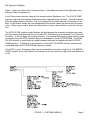
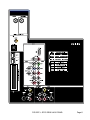
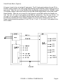
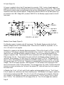
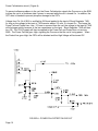
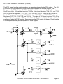
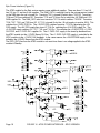
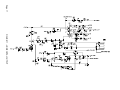
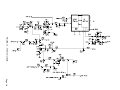
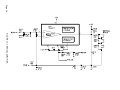
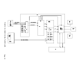
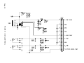
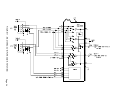
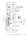
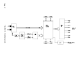
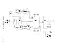
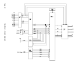
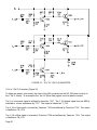
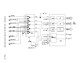
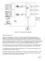
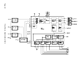
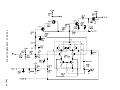
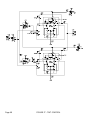
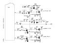
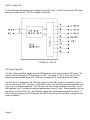
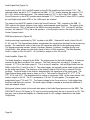
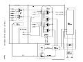
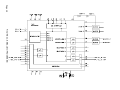
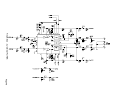
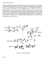
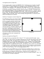
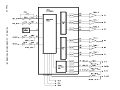
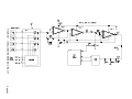
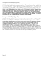
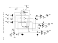
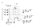
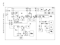
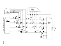
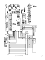
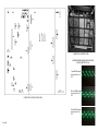
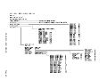
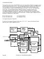
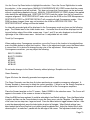
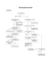
Convergence processor (Figure 35)
The Convergence data is stored in the EEPROM, 7000. The Microprocessor located on the ASC
module reads 1,971 bytes of data from 7000 and writes it to the Convergence Processor, 7052.
Horizontal sync is inverted by 7069, buffered by 7068, and fed to Pin 27 of 7052. Vertical sync is
inverted by 7070, buffered by 7071, and fed to Pin 28 of 7052. The data is processed to produce
the desired convergence correction waveforms which are output on six DACS. During the convergence adjustment procedure, a 180-point alignment grid is output on Pins 16, 17, and 18. This signal is mixed with the OSD to be displayed on the screen. There is only one convergence mode for
this set, 1080i. The output of the DACS is fed to six op-amps before being fed to the Power
Amplifiers located on the SSM. When screen centering is being performed, it is necessary to disable the convergence drive waveform.
Intellisense Convergence correction (Figure 36)
The Intellisense system is only used in the Epic
version. The Philips Intellisense system makes
minor Convergence corrections when the feature is selected by the Customer. When a PTV
is moved from one location to another, minor
Convergence errors will occur due to changes
in the Earth's magnetic field. When Save is
selected during the Convergence Alignment, the
set scans four optical sensors with each of the
three colors. The locations of these sensors
are recorded by the ACS Microprocessor. When
the Customer selects the Intellisense feature,
the sensors are again scanned and the rotation
of the beams for each color is adjusted to the
recorded values.
FIGURE 36
Intellisense Sensing Circuit (Figure 37)
The output of the four sensing Solar Cells is fed to IC 7141, located on the ACS module. Inputs
TBU0, TBU1, and TBU2 from the Convergence Microprocessor are fed to the Decoder which selects
the Solar Cell to be read. The output on Pin 3 is fed to Pin 2 of 7140-1. 7140-1 matches the low
impedance output of 7141 to the high impedance input of 7140-2. Amplifier 7140-2 charges capacitor 2253 with the sample voltage. Due to the high input impedance of 7140-3, 2253 will hold the
sample voltage until it is cleared by transistor 7540. The output of 7140-C is fed to 7101, an Analog
to Digital converter. The Digital reference voltage is fed to the ACS microprocessor where the data
is processed and recorded. When the next location requires sampling, a High is output on Pin 100
of 7100. This turns Transistor 7541 On, discharging capacitor 2253.
The Basic version of the HDRPTV does not have the Sensors installed in the set. However, the
Sensor Test is in the Service Convergence menu. When the Convergence alignments are stored,
the Microprocessor will attempt to read the Sensors. If the Sensor test is selected in the
Convergence Alignment menu, the message will read "Sensors not verified at locations: 1234." This
will not affect the Convergence alignments.
Page 48