1
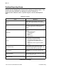
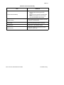
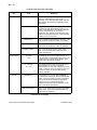
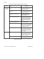
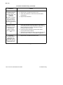
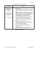
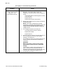
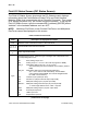
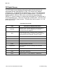
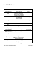
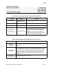
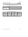
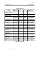
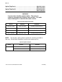
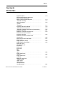
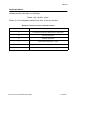
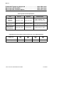
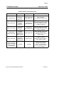
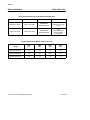
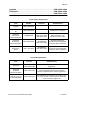
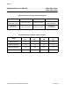
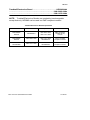
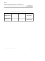
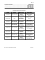
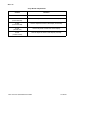
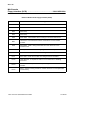
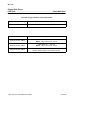
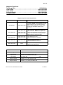
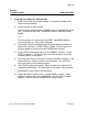
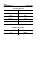
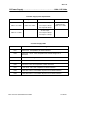
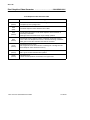
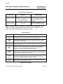
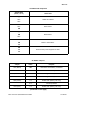
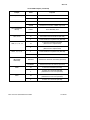
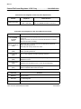
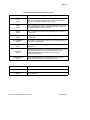
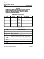
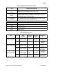
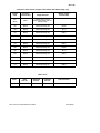
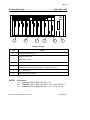
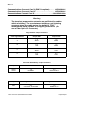
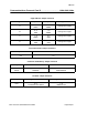
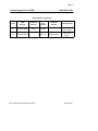
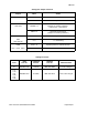
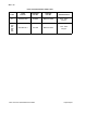
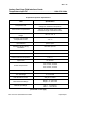
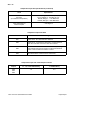
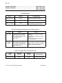
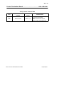
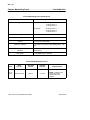
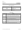
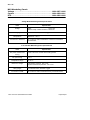
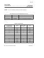
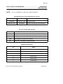
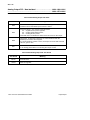
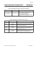
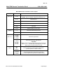
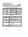
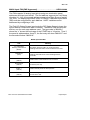
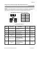
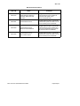
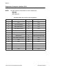
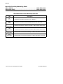
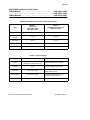
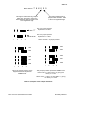
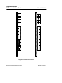
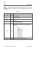
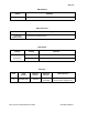
SQ: 6-32
Controller Processor:
MLC . . . . . . . . . . . . . . . . . . . . . . . . . . . . . . . . . . . . . . . . . . . . .
..................................................
SSC . . . . . . . . . . . . . . . . . . . . . . . . . . . . . . . . . . . . . . . . . . . . .
..................................................
MUX and PLC . . . . . . . . . . . . . . . . . . . . . . . . . . . . . . . . . . . .
1984--1439--000x
1984--1249--000x
1984--1442--000x
1984--1371--000x
1984--1494--000x
LEDs and Test Points
LED
Meaning and Response
12 V Fuse Blown
(DS10)
Replace Fuse F1 (Supplies --12 VDC to the card).
+12 V Fuse Blown
(DS9)
Replace Fuse F2 (Supplies +12 VDC to the card).
Block Evaluation
(DS8)
The microprocessor is evaluating an input or output block. With
redundant MultiLoop processors, this LED indicates which one is
active.
CP Access
(DS7)
The Coordinator Processor is accessing the MultiLoop Processor
RAM Memory and transferring configuration and dynamic data to
the NV Memory. If the MultiLoop Processor loses memory, current
data is quickly reloaded from nonvolatile memory.
Interrupt
(DS6)
The MultiLoop Processor is resetting its watchdog timer to prevent
timing out or to acknowledge a synchronizing clock pulse.
5 V Fuse Blown
(DS3)
Card Fault
(DS2)
Card Enable
(DS1)
Replace Fuse F4 (Supplies 5 VDC to the MultiLoop Processor).
A fault has been detected on the MultiLoop Processor or the
ENABLE/DISABLE Switch is in the disable position. If the switch is
enabled and this LED is on, replace the MultiLoop Processor.
The ENABLE/DISABLE Switch is enabled and no hardware faults
are detected on the MultiLoop Processor.
Test Point
Function
Yellow
+5 V (± 0.1 V)
Red
+12 V (± 0.1 V)
Brown
Ground Return
RS3: Service Quick Reference Guide
ControlFiles