1
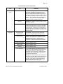
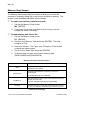
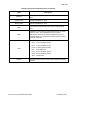
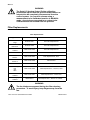
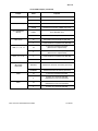
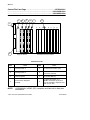
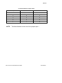
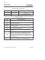
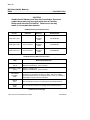
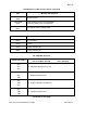
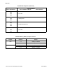
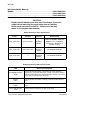
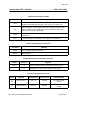
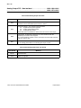
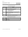
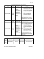
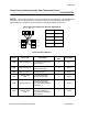
SQ: 1-27
Troubleshooting OI Card Cage Problems
NOTE: All procedures assume that you have found all red fault LEDs
and that they have been corrected before proceeding to the
troubleshooting process.
The procedure is to reduce the Operator Interface (OI) to a configuration
which you know works. From that point you can selectively add removed
components until the faulty component is isolated.
CAUTION
Remove power from the card cage each time a card is
removed or inserted. Do not touch the gold edge
connectors on any board.
If at any point the installation of a circuit card stops the progress of booting,
that card should be replaced. If this process does not find faulty
components, contact FRSI for further assistance.
-
To diagnose a OI Card Cage problem:
1. Remove all OI card cage circuit boards except the Power
Regulator. Put them on a grounded static mat.
CAUTION
Use a grounded wrist strap with a built-in one megohm
resistor for your safety and the protection of static sensitive
circuits. The resistor allows static electricity to drain to
ground and still isolates you from direct ground.
2. If the Power Regulator green LED comes on when power is
applied, the Power Regulator is operational.
3. Install the the OI Processor. When power is applied the red LED
will be on until the processor completes running the
self-diagnostics. When the green LED comes on, the Processor
has passed all the power up diagnostics and should be
considered operational.
4. Install the Video Generator. Either the green or the red LED will
be on until the processor starts to run the diagnostics on this
board. While diagnostics are being run, the red LED will be on.
When the diagnostics are completed successfully, the green LED
is turned on by the processor. As soon as the Video Generator is
installed, you should be able to see the progress of the diagnostic
tests on the screen.
RS3: Service Quick Reference Guide
Troubleshooting