1
DIGITAL VIDEO RECORDER
IV-100CD
Installation &
Operating Manual
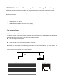
Before trying to connect or operate this product, please read this manual complete
Table Of Contents
SAFETY PRECAUTIONS ................................................................................................3
1. PRODUCT FEATURES ...............................................................................................4
1.1 Product Introduction ...............................................................................................................4
1.2 Product Features ....................................................................................................................4
2. DESCRIPTION OF THE FRONT/REAR VIEW ............................................................5
2.1 Front View ................................................................................................................................5
2.2 Rear View.................................................................................................................................7
2.3 Terminal Block .........................................................................................................................8
3. INSTALLATION ...........................................................................................................9
3.1 Basic Connection....................................................................................................................9
3.2 Hard-Disk Drive Installation................................................................................................. 11
3.3 System Information ..............................................................................................................12
3.4 Updating System Software..................................................................................................13
4. BASIC OPERATIONS................................................................................................14
4.1 Configuring Recording Settings..........................................................................................14
4.2 Recording Operations ..........................................................................................................15
4.3 Playback Operations ............................................................................................................20
4.4 Search Operations................................................................................................................22
4.5 Data Backup ..........................................................................................................................23
4.6 Key Lock Operation..............................................................................................................26
5. MENU SETUP............................................................................................................27
5.1 TIME/ DATE...........................................................................................................................28
5.2 RECORD TIMER ..................................................................................................................29
5.3 REC SETTING ......................................................................................................................30
5.4 ALARM SETTING.................................................................................................................31
1
5.5 COMMUNICATION...............................................................................................................33
5.6 DISK SETTING .....................................................................................................................34
5.7 SYSTEM ................................................................................................................................35
6. SPECIFICATIONS .....................................................................................................37
APPENDIX 1. -- RS-232 Protocol .................................................................................38
APPENDIX 2. -- IDE Hard Disk Installation .................................................................41
APPENDIX 3. -- System Default...................................................................................43
APPENDIX 4. -- O.S.D Message...................................................................................45
APPENDIX 5. -- Network Viewer, Image Viewer, and Image Convert program ........46
APPENDIX 6. -- Index Table .........................................................................................56
APPENDIX 7 -- Network Configuration .......................................................................57
2
SAFETY PRECAUTIONS
All the following safety and operated instructions which will prevent harm or damage to the operator and
other persons should be read before the unit is operated.
WARNING
To prevent fire or shock hazard, do not expose this unit to rain or moisture.
Do not block ventilation openings.
Do not place anything on top of the unit that might spill or fall into it.
Do not attempt to service this unit yourself as opening or removing covers may expose you to
dangerous voltage or other hazards. Please refer all servicing to qualified service personnel.
Do not use liquid cleaners or aerosols for cleaning.
To prevent fire or electric shock, do not overload wall outlets or extension cord.
This unit must be grounded to reduce the risk of electric shock hazard.
CAUTION
Danger of explosion if the Lithium battery (RTC Battery) is incorrectly replaced.
Danger of explosion if battery is incorrectly replaced. Replace only with the same or equivalent type
recommended by the manufacturer. Dispose of used batteries according to the manufacturer’s
instructions.
3
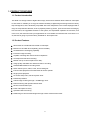
1. PRODUCT FEATURES
1.1 Product Introduction
This DVR is a storage media of digital video image, which uses hard-disk drives instead of VCR tapes
to store video. It enables you to enjoy the extreme flexibility of digital image archiving instead of clumsy
tape management, and is absolutely compatible with most multiplexers in the market. Equipped with a
range of comprehensive features, such as playback picture-by-picture, quick access video recording by
time and event, the upgradable software of the system, the expandable capacities of hard drive, and
much more, the DVR will make your applications far more flexible and effective than ever before. For
all, the DVR is going to prove the timely substitute for Time-lapse VCR.
1.2 Product Features
* Stores video in hard-disk drives instead of VCR tapes.
* Maximum 3 hard-disk drive capability. (One removable)
* Hard-disk drive hot-swapping capability.
* Pre-alarm image recording.
* Capable of working with various known multiplexers.
* Time-lapse and real-time recording.
* Refresh rate up to 60 FPS (50 FPS for PAL).
* Image quality selectable at 3 different levels for recording.
* Schedule/Manual/Alarm recording mode.
* Quick search by time, alarm, event, and recording list.
* Fast and slow playback of recorded video at various speeds.
* Single-picture playback.
* On-screen setup menu, title and system timer.
* Password protection.
* Critical image archiving through 1.44 MB floppy drive.
* Disk-full warning and operation status LEDs.
* RS-232 communication port.
* Power interruption recovery.
* Operation-status record log.
* Distributing live and recorded images through TCP/IP network environment.
4
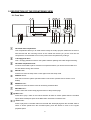
2. DESCRIPTION OF THE FRONT/REAR VIEW
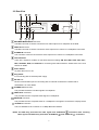
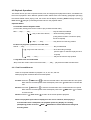
2.1 Front View
1
2
3
5 6
4
8
7
9 10 11
STOP
SETUP
DISPLAY
SEARCH
RETURN
PLAY
FWD
REV
ENTER
/
SAVE
REC
MONITOR
MUX
PAUSE
DVR
STEP
/
18
22 20
19
23 21
17 16 15
14
12
13
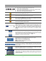
Hard-disk drive compartment.
This compartment allows you to install a drive mostly for backup purpose. Make sure the drive is
well secured with the mounting screws in the mobile rack before you put the rack into the
compartment. And remember to turn on the power of the compartment by locking it.
1.44 floppy disk drive.
This 1.44 floppy disk slot is used for the system software updating and critical images archiving.
Hard disk compartment lock:
To secure a hard disk in place. Unlock this compartment before you remove the hard disk from
the slot without turning off the device.
SETUP button:
Press this to enter the setup menu. Press again to exit the setup mode.
DISPLAY button:
Push this to show the system operation status on the screen. (Please refer to section 3.3 for
details)
SEARCH button:
Press this to enter the search mode for accessing recorded video.
RETURN button:
Press to leave the current setup page and return to the previous page.
REV button:
Press this to play a video in the reverse direction at faster or slower speeds than the recorded
speed. Each subsequent press of the REV button increases or slows the rate.
PLAY button:
Press to play back a recorded video from the hard disk. While playing back the recorded video at
faster or slower speeds than the recorded speed, press this button to return to the regular
playback speed.
5
STOP button:
Press this to stop playing back a recorded video.
FWD button:
Press this to play a recorded video in the forward direction at faster or slower speeds than the
recorded speed. Each subsequent press of the FWD button increases or slows the rate.
PAUSE / STEP button:
In a playback display, press this to freeze the display. During the freeze, press this to display one
frame/field of a picture at a time in the forward direction.
REC button:
Push this to start recording the video into hard disks while in the live display mode.
*MUX /
●DVR
button:
Press this to switch between the multiplexer decoded video and the encoded video to be
displayed as connected with a multiplexer. When the button light is on it indicates the unit is
displaying the decoded video (The pictures are not multiplexing). In this mode, the unit doesn’t
display the OSD message of the unit on the screen. However, it doesn’t affect the unit’s OSD
message which is recorded into hard-disk drive. When the button light is off it indicates the unit is
displaying encoded video (The picture is switching swiftly).
Right / Left buttons:
Press these two buttons to highlight desired items in the menu setup mode. For Key Lock
operation, press these two buttons simultaneously once; to disable Key Lock, press these two
buttons simultaneously again.
Up / Down buttons:
Press these two buttons to select the desired contents for programming in the menu setup mode.
ENTER
/
SAVE
ENTER/SAVE Button:
Press to enter the selected item and save the setting in the menu setup mode. During the
playback of a video, if you wish to save a specific image to a floppy disk, press the PAUSE button
to freeze the picture first and then press this button to proceed.
Indicator of Alarm Recording Mode:
Light up to signal the alarm record setting is on.
Indicator of Timer Recording Mode:
Light up to signal the scheduled record setting is on.
Indicator of Hard Disk Status:
Indicates the operation status of the hard-disk drives. Green light up indicates the hard-disk drive
is storing or retrieving the data. Red light up signals the hard-disk drive is getting filled up.
Power Indicator:
Indicates the power status of the unit.
6
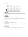
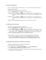
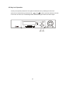
2.2 Rear View
5
4
ALM.RST
6
GND
7
ALM. IN
8
REC
9
ALM.OUT
S-VIDEO
FULL
VIDEO
IN
5
4
GND
MUX MAIN
MONITOR
3
SW.OUT
2
GND
1
3
2
1
This device complies with
part 15 of the FCC Rules.
Operation is subject to the
following two conditions:
(1) This device may not cause
harmful interference. And
(2) this device must accept
any interference received,
including interference that
may cause undesired operation.
OFF
ON
POWER
AC
OUT
100
240V
11
10
9
8
6
7
MUX MAIN MONITOR IN Connector:
This BNC connector is used to connect the live video output from a multiplexer to the DVR.
VIDEO IN Connector:
This BNC connector is used to connect the video output from a camera or a multiplexer to the DVR.
S-VIDEO IN Connector:
This connector is used to connect the S-video output from a camera or a multiplexer to the DVR.
Terminal Block:
There are 9 exposure contacts on this terminal block including SW. Out, GND, ALM. OUT, FULL,
REC, ALM RST, GND, and ALM. IN for connecting with external devices. Please refer to the next
section for details.
Power Switch:
To power the unit on or off.
Plug Outlet:
For connecting with an external power supply.
RS-232 Port:
RS-232 communication port for connecting with an external control device. Please refer to
APPENDIX 1 for more details.
S-VIDEO OUT Connector:
This provides the device’s S-video signal to a multiplexer.
VIDEO OUT Connector:
This provides the unit’s composite video signal to a multiplexer.
MONITOR Connector:
This provides the unit’s composite video or a multiplexer’s live signal if connected to a display device.
10 BASE-T Connector:
This is a standard RJ-45 connector for 10 Mbps Ethernet networks.
NOTE: The DVR only processes the video signal from S-VIDEO IN
video signals simultaneously from both “S-VIDEO IN
7
connectors when receiving
” and “VIDEO IN
” connectors.
SW.OUT
GND
ALM.OUT
FULL
GND
REC
ALM.RST
GND
ALM. IN
2.3 Terminal Block
9
8
7
6
5
4
3
2
1
1. ALM IN: (INPUT)
This is an alarm input, which can be programmed in the menu system to Normally Open or Normally
Closed. (Active low, 5V)
2. GND:
Ground Contact.
3. ALM RST: (INPUT)
This terminal connects to an alarm-clear device for clearing the alarm. (Active low, 5V)
4. REC: (INPUT)
This terminal connects an external switch to turn the recording function of the DVR on/off. (Active low,
5V)
5. GND:
Ground Contact.
6. FULL: (OUTPUT)
This terminal sends out the full-disk signal. (Active low, 5V)
7. ALM OUT: (OUTPUT)
This is an alarm output relay. Connect this to an external device like buzzers or lights. (Active low, 5V)
8. GND:
Ground Contact.
9. SW OUT: (OUTPUT)
This terminal, sending out the timing signal (falling/negative) to a multiplexer, connects to a
multiplexer’s trigger terminal so that the multiplexer can switch to use the same recording speed as the
DVR.
8
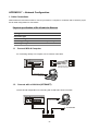
3. INSTALLATION
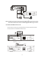
Please follow the instructions and the diagram below to set up the system.
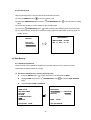
3.1 Basic Connection
Please set the MULTIPLEXER option to OFF on the REC Setting page in the setup menu when it is
connected with a single camera. (Please refer to section 5.3 MULTIPLEXER option)
CONNECTING WITH A SINGLE CAMERA
5
ALM. IN
6
REC
7
GND
8
ALM.RST
9
FULL
ALM.OUT
S-VIDEO
GND
VIDEO
IN
GND
MUX MAIN
MONITOR
SW.OUT
Camera
4
3
2
1
This device complies with
part 15 of the FCC Rules.
Operation is subject to the
following two conditions:
(1) This device may not cause
harmful interference. And
(2) this device must accept
any interference received,
including interference that
may cause undesired operation.
OFF
ON
POWER
AC
OUT
100
240V
Monitor
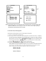
CONNECTING WITH A MULTIPLEXER
To match the multiplexer’s recording speed, please set the MULTIPLEXER option to ON on the
REC Setting page in the setup menu when it is connected with a multiplexer. (Please refer to
section 5.3 MULTIPLEXER option)
When a Multiplexer is connected, you can add a RS-232 connection to synchronize the operation
mode between the DVR and the MUX. The MUX will automatically switch between live or playback
mode in corresponding to the state of the DVR. Follow the instructions below to establish the
connection.
1. Connect the DVR with the multiplexer with a null modem cable. (For the details of pin configuration
of RS-232 please refer to 1. Setup, Appendix 1)
2. Set the RS-232 option to MASTER in the COMMUNICATION page of the main menu. Select a
communication baud rate for MUX except Remote.
9
Multiplexer
Trig In
7
6
5
4
ALM.RST
REC
8
GND
GND
9
ALM. IN
SW.OUT
S-VIDEO
GND
VIDEO
IN
FULL
MUX MAIN
MONITOR
ALM.OUT
S-Video
3
2
1
This device complies with
part 15 of the FCC Rules.
Operation is subject to the
following two conditions:
(1) This device may not cause
harmful interference. And
(2) this device must accept
any interference received,
including interference that
may cause undesired operation.
OFF
ON
POWER
AC
OUT
100
240V
Main monitor
NOTE: The DVR only processes the video signal from S-VIDEO IN
video signals simultaneously from both “S-VIDEO IN
connector when receiving
” and “VIDEO IN
” connectors.
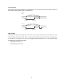
ATTACHING AN EXTERNAL DEVICE TO DVR
Connect an alarm out, alarm input, and a peripheral device as shown diagram below. Network
connection please refer to APPENDIX 5 Network Function.
Alarm Reset
(Normally Open)
Lamp
Alarm
5
ALM. IN
6
GND
7
REC
8
ALM.RST
9
FULL
ALM.OUT
S-VIDEO
GND
VIDEO
IN
SW.OUT
MUX MAIN
MONITOR
GND
(Normally Open)
4
3
2
1
This device complies with
part 15 of the FCC Rules.
Operation is subject to the
following two conditions:
(1) This device may not cause
harmful interference. And
(2) this device must accept
any interference received,
including interference that
may cause undesired operation.
OFF
ON
POWER
AC
OUT
100
240V
Lamp or buzzer
or REC IN contact of another DVR
Vcc
ALM.RST
GND
ALM. IN
7
REC
8
FULL
9
GND
S-VIDEO
ALM.OUT
VIDEO
IN
SW.OUT
MUX MAIN
MONITOR
GND
REC Switch
6
5
4
3
2
1
This device complies with
part 15 of the FCC Rules.
Operation is subject to the
following two conditions:
(1) This device may not cause
harmful interference. And
(2) this device must accept
any interference received,
including interference that
may cause undesired operation.
OFF
ON
POWER
AC
OUT
100
240V
10
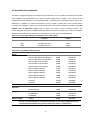
3.2 Hard-Disk Drive Installation
The DVR is equipped with three compartments of hard disk drive. The unit usually comes with one hard-disk
drive installed in the compartment HD1, which is default-configured as a master. If you need a second
hard-disk drive to be installed in the compartment HD2 or compartment HD3 (Mobile), please contact your
distributors or installers for specific instructions on how to install it. Please don’t serve yourself before
consulting your installers. If there is only one hard-disk drive in the mobile compartment, please set the HD3
USAGE option to REC/PLAY (Please refer to section 5.6) before proceed recording function. The
jumper-settings arrangement of installed hard-disk drives for the system (Table 3.2 A) and the compatible
hard-disk drives (Table 3.2 B), which can be used with the unit, are shown in the tables below.
Table 3.2 A. The jumper settings of hard disk drives in the system
Location
Jumper
IDE 1
Compartment HD 1
Master (Default)
IDE 1
Compartment HD 2
Slave
IDE 2
Compartment HD 3
Master
Table 3.2 B. Compatible hard-disk drives
Manufacturer
Maxtor
Model
Capacity
Rotation
Diamond Max D540X-4D 4D040H2
40GB
5400 RPM
Diamond Max D540X-4D 4D060H3
60GB
5400 RPM
Diamond Max D540X-4D 4D080H4
80GB
5400 RPM
Diamond Max VL40-34098H4
40GB
5400 RPM
Diamond Max VL40-33073H3
30GB
5400 RPM
Diamond Max VL40-32049H2
20GB
5400 RPM
Maxtor 536DX 4W100H6
100GB
5400 RPM
Maxtor 536DX 4W080H6
80GB
5400 RPM
Maxtor 536DX 4W060H4
60GB
5400 RPM
Maxtor 536DX 4W040H3
40GB
5400 RPM
Maxtor 536DX 4W030H2
30GB
5400 RPM
4G120J6
120GB
5400RPM
4G160JB
160GB
5400RPM
IBM
DTLA-305040
40GB
5400 RPM
Quantum
Fireball Lct
20GB
5400 RPM
Fireball PlusLM
20GB
5400 RPM
ST330621A/P
30GB
5400 RPM
ST340823A/P
40GB
5400 RPM
ST380020A
80GB
5400 RPM
WD800
80GB
5400 RPM
Seagate
Western Digital
NOTE: Hard-disk drives not shown on this list have not been tested by the engineering team
and are not recommended for use with this product. For the latest updated list on the
recommended hard disk drives, please contact your dealers or distributors.
11
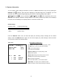
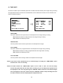
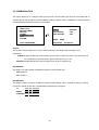
3.3 System Information
You can display system settings information as shown on Table 3.3 A below at any time by pressing the
. However, when the DVR is displaying a decoded image from a multiplexer, you must
DISPLAY button
first switch the unit to encoded image displaying (The pictures is switching swiftly and the light of
*MUX/ ● DVR button
is off) by pressing the*MUX/ ● DVR button
. Each sequential press of the
DISPLAY button displays a different message detailed in the following example. By default, the unit displays
time, date, and an indicating bar of capacity status on a monitor as shown next.
Default display
(Capacity Used)
(Capacity Remaining)
09- 05-2001
16:13:02
(Date)
(System Time)
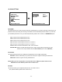
Press the DISPLAY button once; the DVR will display the following sample message plus the default
display. Press the DISPLAY button again; the unit will not display any OSD message. Press the button
one more time to back to the default display.
Table 3.3 A.
Description of Table 3.3 A
(1+2: 76GB): Total capacity of installed hard disk, 76 GB
1+ 2: 76G
11.2 HR
QUALITY: HIGH
NTSC
RATE: 6 HR
20 F/S
(11.2 HR): Total 11.2 hour recording time available
(
): Timer record activated
(
): Alarm record activated
(QUALITY: HIGH): Record quality setting, HIGH
(NTSC): NTSC system
HD P
SIZE
POS
1
Y
38 G
2.5%R (P)
2
Y
38 G
0%R (P)
3
.
.
(RATE: 6 HR): Setting of Record time mode, 6 hours
(20 F/S): Record speed setting, 20 fields/sec
(HD): Hard disk Compartment
(P): Y Hard disk installed; . No hard disk installed
(SIZE 38GB): The capacity of the installed hard disk
POS: Percentage of system; R: Recording; P: Playback
12
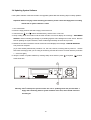
3.4 Updating System Software
If the system software of the DVR needs to be upgraded, please take the following steps to safely update it.
Important: Before carrying out the following procedures, please ensure the floppy disk is working
and the file of system software is intact
1. Turn off the DVR.
2. Insert the floppy disk into the built-in floppy drive of the unit.
3. Hold down the
and
buttons simultaneously, and then turn on the unit.
4. Keep holding down the buttons until the DVR sounds a tone and display the message “ SOFTWARE
UPDATE” and an indicating percentage of proceeding against a blue background on the screen. Now the
DVR is updating the system software, which will take approximately 90 seconds to process.
5. Restart the unit when the device sounds a tone twice and displays the message “ PLEASE RESTART”
The process is complete.
(If you have already followed the procedure 1~5, the unit, however, not being able to power on. Please
first check if the floppy disk you are using is functioning and the file is intact. And then start the procedure
1 ~ 5 all over again.)
and pause
6. Verify the version of system software by entering setup menu and then press
buttons
at the same time.
1
STOP
SETUP
DISPLAY
SEARCH
RETURN
PLAY
FWD
REV
ENTER
/
SAVE
REC
MONITOR
MUX
PAUSE
DVR
STEP
/
2
Warning: Don’t Interrupt the process while the unit is updating itself and proceed with a
floppy disk containing with no system software of the unit, which would cause the
unit hang on.
13
4. BASIC OPERATIONS
This section shows you how to operate and manage the DVR when it gets in the way.
4.1 Configuring Recording Settings
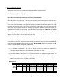
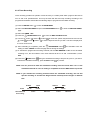
Recording Time settings (Recording Rate and Picture Quality Setting)
Recording time will vary depending on the image size, recording rate, and the capacity of hard-disk drive.
Generally, the DVR comes with a built-in hard-disk drive for continuous recording from one to four weeks
under most recording conditions. The table below shows the possible recording times based on a 20GB
hard-disk drive at certain refresh rates and the corresponding image quality. With one or more hard-disk
drive (s) in operation, please calculate the recording time using the table below in accordance with your
requirement. For a NTSC unit, for example, if the unit is set to record images with HIGH quality at a 60 fps
record rate, normally a 20GB hard-disk drive will be filled in 3 hours (See the gray area in the table). If the
total capacity of 80GB hard-disk drives is in use under the same refresh rate and picture quality, it will be
filled in 12 hours (4 times the rate of a 20GB hard-disk drive).
Set up the REC Time Mode when a multiplexer is connected
If a multiplexer is connected, for optimum image recording and playback, the record speed of the multiplexer
must be correctly adjusted to match the DVR and set the MULTIPLEXER option on the setup menu to ON.
This is can be done by either of methods detailed below.
(1) If a multiplexer is connected for use, you can program the REC time mode of the multiplexer by
referring to the table below (each refresh rate refers to one REC time mode).
(2) Connect the SW. OUT terminal on the rear panel of the DVR to the multiplexer’s trigger contact. The
DVR will provide the timing signal (Negative/Falling) to the multiplexer. Thus, if the DVR change the
recording speed, the multiplexer will automatically adjust the record to match. A 2-hour timing signal in
NTSC or 3-hour one in PAL is constantly negative/falling.
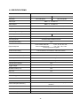
NTSC System
Possible Recording Time HDD=20 Gigabytes
HIGH
3 hr
9 hr
18 hr
36 hr
72 hr
144 hr
252 hr
720 hr
STANDARD
4.5 hr
13.5 hr
27 hr
54 hr
108 hr
216 hr
378 hr
1080 hr 1620 hr 2160 hr
BASIC
6 hr
18 hr
36 hr
72 hr
144 hr
288 hr
504 hr
1440 hr 2160 hr 2880 hr
Refresh Rate (Field/Sec)
60
20
10
5
2.5
1.25
0.63
0.25
0.16
0.13
REC Time Mode
2 hr
6 hr
12 hr
24 hr
48 hr
96 hr
168 hr
480 hr
720 hr
960 hr
Image
Quality
Setting
14
1080 hr 1440 hr
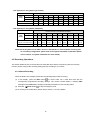
PAL System (For using with single camera)
Possible Recording Time HDD=20 Gigabytes
High
3.5 hr
Standard
Basic
7 hr
14 hr
28 hr
5.5 hr
11 hr
22 hr
7 hr
14 hr
28 hr
Refresh Rate (Field/Sec)
50
25
REC Time Mode
3 hr
6 hr
Image
Quality
56 hr
112 hr
196 hr
560 hr
840 hr
1120 hr
44 hr
88 hr
176 hr
56 hr
112 hr
224 hr
308 hr
880 hr
1320 hr 1760 hr
392 hr
1120 hr 1680 hr 2240 hr
12.5
6.25
3.13
1.56
0.89
0.31
0.21
0.16
12 hr
24 hr
48 hr
96 hr
168 hr
480 hr
720 hr
960 hr
PAL System (For using with a multiplexer)
Possible Recording Time HDD=20 Gigabytes
Image
Quality
High
3.5 hr 10.5hr
24.5hr
38.5hr
73.5hr
Standard
5.5 hr 15.8hr
36.8hr
57.8hr
110.3hr 215.3hr
372.8hr 1055.3hr 1580.3hr 2105.3hr
Basic
143.5hr
248.5hr
703.5hr 1053.5hr 1403.5hr
7 hr
21.0hr
49.0hr
77.0hr
147.0hr 287.0hr
497.0hr 1407.0hr 2107.0hr 2807.0hr
Refresh Rate (Field/Sec)
(Figures on the setup menu)
50
(50)
16.7
(25)
7.14
(12.5)
4.55
(6.25)
2.38
(3.13)
1.22
(1.56)
0.70
(0.89)
0.25
(0.31)
0.17
(0.21)
0.12
(0.16)
REC Time Mode
3 hr
6 hr
12 hr
24 hr
48 hr
96 hr
168 hr
480 hr
720 hr
960 hr
NOTE: Recording times on the tables above are estimated. For actual available recording time
of a recording configuration, please refer to the system information of the DVR. (Please
refer to section 3.3 system information for more details.)
4.2 Recording Operations
This section details the way to record video into hard-disk drives. Before commencing with the recording
function, please configure the recording setting properly according to your needs.
4.2.1 Manual Recording
When the DVR is in live display mode, take the following steps to start recording:
(1) In live display, press the REC button
to record video into a hard disk drive with the
corresponding programmed recording settings. The monitor should display a flashing REC
message and the REC button will light up indicating the DVR is in the recording status.
(2) Press the
STOP button
to stop recording any time.
(3) To access just recorded video, please refer to section 4.4 for more details.
15
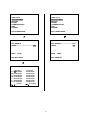
4.2.2 Timer Recording
Timer recording provides two periods of time each day in a weekly table which programs the DVR to
turn on and off at specified times. This way the DVR will start and stop recording according to the
programmed schedule. Please take the following steps to program the scheduled recording.
to enter the MAIN MENU.
(1) Press the SETUP button
(2) Select the RECORD TIMER and press the ENTER/SAVE button
to enter the RECORD TIMER
page.
(3) Select the TIMER-SET.
(4) Press the
ENTER
(5) Use the
button
/
SAVE
ENTER/SAVE button
button
and the
and the
to enter the REC SCHEDULE table.
button
button
to locate the specific day/hour/minute and use the
to set the day/hour/minute you wish. The time is displayed in
a 24-hour clock format.
(6) After scheduling is completed, press the
ENTER
/
SAVE
ENTER/SAVE button
and set OK to save the
setting or select CANCEL to leave the page without saving the settings.
(7) To activate the programmed recording schedule, set the REC ENABLE to ON. As the scheduled
recording is on, the red indicator of the Timer Record will be on as well. To deactivate it, set to
OFF.
(8) Press the
STOP button
during the scheduled recording to stop it at any time. If you wish to
to proceed.
continue the scheduled recording, press the REC button
NOTE: You can proceed to start the scheduled recording from the current time if it is in the
scheduled interlude as soon as setting is completed. Press the REC button to proceed.
NOTE: If you activate the recording function before the scheduled recording, the unit will
operate recording as showed the diagram below and keep those Images in different
files.
03:00
Start Manual
Recording
START
END
START
06:00
08:00
12:00
Timer
Manual
16
Timer
END
14:00
Manual
MAIN MENU
MAIN MENU
TIME/ TITLE
RECORD TIMER
RECORD
ALARM
COMMUNICATION
DISK
SYSTEM
TIME/ TITLE
RECORD TIMER
RECORD
ALARM
COMMUNICATION
DISK
SYSTEM
GOTO TIMER PAGE
GOTO TIMER PAGE
RECORD TIMER
RECORD TIMER
REC ENABLE
TIMER---------------------------------- SET
REC ENABLE------------------------OFF
TIMER
ON
MAIN
MAIN
PAGE
SET REC TIMER
SET TIMER ON
REC SCHEDULE
START END
S : 00-00:00-00
M: 00-00:00-00
T : 00-00:00-00
W: 00-00:00-00
T : 00-00:00-00
F : 00-00:00-00
S : 00-00:00-00
TO MOVE
PAGE
START END
00:00-00:00
00:00-00:00
00:00-00:00
00:00-00:00
00:00-00:00
00:00-00:00
00:00-00:00
TO CHANGE
17
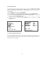
4.2.3 Alarm Recording
Take the following steps to activate the programmed alarm recording. For ALM REC RATE, ALM REC
QUALITY, ALARM STATUS, ALM DURATION, and PRE-ALARM settings, please refer to section 5.4
for more details.
(1) Press the SETUP button
to enter the MAIN MENU.
(2) Select ALARM and press the
ENTER
/
SAVE
ENTER/SAVE button
to enter the ALARM SETTING.
(3) Set the desired REC RATE, REC QUALITY, ALM TYPE, and ALM DURATION for use. If pre-alarm
recording is required, set PRE-ALARM to ON.
(4) To activate the alarm recording, set ALM OPERATION to ON. To deactivate it, set ALM
OPERATION to OFF.
ALARM SETTING
MAIN MENU
ALM OPERATION
REC RATE
REC QUALITY
ALM TYPE
ALM DURATION
PRE- ALARM
TIME/ TITLE
RECORD TIMER
RECORD
ALARM
COMMUNICATION
DISK
SYSTEM
MAIN
GOTO ALARM PAGE
: OFF
: 60F/S
: HIGH
: NO
: NON STOP
: OFF
PAGE
ALARM REC ENABLE
4.2.4 Externally triggered Recording
By connecting the REC exposure contact on the rear panel of the DVR with an external switch, you can
activate/deactivate the recording function of a DVR. The file will be kept with a prefixed “R”. Please
refer to section 2.3 for more details.
18
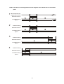
NOTE: The status of recording operations as the diagrams shown below when an alarm takes
place.
1
Manual or Externally
Triggered Recording
Alarm Takes Place
Actual Recording
Speed
2
Normal
Alarm
Normal
Normal
Alarm
Normal
Timer Recording
Alarm Takes Place
Actual Recording
Speed
3
Timer Recording
Alarm Takes Place
Actual Recording
Speed
4
Normal
Alarm
Timer Recording
Alarm Takes Place
Actual Recording
Speed
Alarm
Normal
19
4.3 Playback Operations
This section shows you how to operate the fast, slow, and single-picture playback functions, and details how
the unit is to playback a file in different operation status. Please refer to the following paragraphs specifying
the relevant details. When playing a file, the monitor should display a flashing PLAY message and the
PLAY button
will light up indicating that the DVR is in the playback status.
Operation Status
A. From REC mode to Playback mode
(In live mode, directly press “PLAY” button to play a latest recorded video)
REC→〔Stop〕→〔Play〕………………………………………Play the latest recorded file
〔Play: to the end of the file〕……Show the ending message
(Using search function or rewind to replay
the file if required)
〔Stop〕→〔Play〕……………….Play the file from the stop position
B. Search to play back a particular recorded video
Search→〔Play〕………………………………………………….Play a selected file
〔Play to the end of the file〕………………Show the ending message
(Search again or rewind to replay the file if
required)
〔Stop〕→〔Play〕………………………….Play the file from the stop position
C. Play Back From The Oldest Data
〔Stop: Press the “STOP” button for three seconds〕→〔Play〕..play back the oldest recorded video
4.3.1 Fast Forward/Reverse
There are 5 speeds available for playback: 2x, 4x, 8x, 16x, and 30x.
While playing back recorded video at recorded speed:
Forward: Press the
FWD button
to view the recorded video in the forward direction at a speed
faster than the recorded speed. Each subsequent press of the
FWD button increases the
rate.
Reverse: Press the
REV button
to view the recorded video in the reverse direction at a speed
faster than the recorded speed. Each subsequent press of the
REV button
increases
or slows the rate.
Normal: Press the
PLAY button
to return to the normal speed of playback.
NOTE: The playback speed will be displayed on the screen. However, when playing a
recorded video from a multiplexer, the playback speed only display on encoding
(multiplexing) mode. Press the *MUX /
●DVR
encoding mode.
20
button to switch between decoding and
4.3.2 Slow Forward/Reverse
There are 4 speeds available for a slow playback: 1/2, 1/4, 1/8, 1/16. Follow the instructions below to
proceed with a slow playback.
While playing back recorded video at the recorded speed:
PAUSE/STEP button
(1) Press the
(2) Forward: Press the
FWD button
for the slow playback mode.
to view the recorded video in the forward direction at a
speed faster than the recorded speed. Each subsequent press of the FWD button slows
the rate.
REV button
(3) Reverse: Press the
to view the recorded video in the reverse direction at a
speed faster than the recorded speed. Each subsequent press of the REV button slows
the rate.
(4) Normal: Press the
PLAY button
to return to the normal speed of playback.
4.3.3 Play Back Picture-by-picture
While playing back recorded video at the recorded speed:
(1) Press the
(2) Press the
PAUSE/STEP button
PAUSE/STEP button
for the picture-by-picture mode.
to display one frame/field of a picture at a time in the
forward direction. (When playing back recorded video recorded by a multiplexer, each
sequential press of the
(3) Press the
PAUSE/STEP button
PLAY button
will display each camera in sequence.)
to return to the normal speed of playback.
NOTE: If flickering condition of an image occurs during playing back picture by picture,
please set the FLICKER REDUCT option to ON in the SYSTEM page of the setup menu.
However, when this function is activated, the picture quality might be degraded in a way.
4.3.4 Play Back Recorded Video from a HDD of the mobile rack
To play back a recorded video from a HD3, take the following steps:
(1) Press setup button to enter the setup menu.
(2) Select DISK and press the
ENTER
/
SAVE
ENTER/SAVE
button to enter DISK SETTING page.
(3) Set the HD3 USAGE to REC/PLAY and then exit the setup menu.
(4) Use the search function to access desired recorded video. Specific operation details please refer to
the next section 4.4 Search Operations.
21
4.4 Search Operations
This section shows you how to access recorded video.
4.4.1 Full List Search
Take the following steps to proceed with the full list search function.
(1) Press the SEARCH button
to enter the search mode.
(2) Select the FULL LIST and press the
recorded video.
ENTER
/
ENTER/SAVE
SAVE
button to access the complete list of
ENTER
/
(3) Highlight the specific recorded video of your requirement and press the
ENTER/SAVE button
SAVE
to display the selected video.
Up/Down buttons
(Key Operation: Press
to select a video; Press
Right /
to flip over a page.)
Left buttons
HD 1
1 2001-02-01 12: 20
A 2 2001-02-01 13:30
3 2001-03-02 14:20
4 2001-03-02 14:20
R 5 2001-03-02 14:20
HD 2
T 6 2001-02-01 13:30
SEARECH
FULL LIST
ALARM LIST
TIME SEARCH
NOTE: T: Timer recording; R: External trigger recording; A: Alarm recording.
4.4.2 Alarm list Search
Take the following steps to proceed with the alarm list search function.
(1) Press the SEARCH button
to enter the search mode.
(2) Select the ALARM LIST and press the
alarm-event recorded video.
ENTER
/
SAVE
ENTER/SAVE button
to access the complete list of
(3) Highlight the specific recorded video of your requirement and press the
button
ENTER
/
SAVE
ENTER/SAVE
to display the selected video.
(Key Operation: Press
Up/Down buttons
Left buttons
to select a video; Press
to flip over a page)
A 1 2001-02-01 12: 20
A 2 2001-02-01 13:30
A 3 2001-03-02 14:20
SEARCH
FULL LIST
ALARM LIST
TIME SEARCH
22
Right /
4.4.3 Time Search
Take the following steps to proceed with the time list search function.
(1) Press the SEARCH button
to enter the search mode.
(2) Select the TIME SEARCH and press the
page.
ENTER
/
SAVE
ENTER/SAVE button
to access the time setting
(3) Set the time period you wish to search for the recorded video.
ENTER
/
(4) Press the
ENTER/SAVE button
to start searching and displaying the concerned image.
(5) If no video is found, please return to the time setting page and repeat steps (3) and (4) again for
SAVE
another search.
TIME SEARCH
SEARCH
MM DD YEAR HH MM
08 17 2001 00 : 00
FULL LIST
ALARM LIST
TIME SEARCH
4.5 Data Backup
4.5.1 Backup Operations
There are three ways available to duplicate the recorded video from HD 1 and HD 2 to HD 3.
Please take the following steps to proceed.
(1) Set HD 3 to BACKUP first. Take the following steps.
Press the SETUP button
Highlight DISK and press the
to enter the setup mode and select the DISK.
ENTER
/
SAVE
ENTER/SAVE button
to enter the DISK SETTING
page.
Then set HD 3 USAGE to BACKUP.
MAIN MENU
DISK SETTING
TIME/ TITLE
RECORD TIMER
RECORD
ALARM
COMMUNICATION
DISK
SYSTEM
REFORMAT
HD 3 USAGE---------- REC/PLAY
BACKUP
BACKUP
GOTO DISK PAGE
SET HD3 USAGE
MAIN
23
PAGE
(2) FULL: Duplicating all the recorded video from HD1 and HD 2 to HD3.
Stay on the DISK SETTING page.
Use the
ENTER
/
SAVE
Up/Down buttons
ENTER/SAVE button
to highlight BACKUP; select FULL, then press the
to proceed.
MAIN MENU
DISK SETTING
TIME/ TITLE
RECORD TIMER
RECORD
ALARM
COMMUNICATION
DISK
SYSTEM
REFORMAT
HD3 USAGE
BACKUP----------------FULL
ALARM
SELECT
GOTO DISK PAGE
BACKUP ALL TO HD3
MAIN
PAGE
ALARM: Duplicating all the alarm-event recorded video from HD 1 and HD 2 to HD 3.
Stay on the DISK SETTING page.
Up/Down buttons
Use the
ENTER
/
SAVE
ENTER/SAVE button
to highlight BACKUP; select ALARM, then press the
to proceed.
MAIN MENU
DISK SETTING
TIME/ TITLE
RECORD TIMER
RECORD
ALARM
COMMUNICATION
DISK
SYSTEM
REFORMAT
HD3 USAGE
BACKUP----------------FULL
ALARM
SELECT
GOTO DISK PAGE
BACKUP ALARM TO HD3
MAIN PAGE
SELECT: Duplicating a particular recorded video from HD1 and HD 2 to HD3.
Stay on the DISK SETTING page.
Up/Down buttons
Use the
the
ENTER
/
SAVE
ENTER/SAVE button
Press the
to highlight BACKUP, select SELECT and then press
to list all the recorded video.
Up/Down buttons
to select the desired clip and press the SETUP
button to mark it.
After completing the selection, press the
24
ENTER
/
SAVE
ENTER/SAVE button
to proceed.
MAIN MENU
DISK SETTING
TIME/ TITLE
RECORD TIMER
RECORD
ALARM
COMMUNICATION
DISK
SYSTEM
REFORMAT
HD3 USAGE
BACKUP----------------FULL
ALARM
SELECT
MAIN PAGE
BACKUP PART TO HD3
HD1
A 1 2001-02-01
2 2001-02-01
A 3 2001-03-02
4 2001-04-01
12:20
03:30 +
04:20 +
13:30
TOTAL: 41 M
READY TO GO
OK CANCEL
NOTE: If the capacity of HD 3 is not sufficient to store all selected video, a warning message “HD3
SPACE NOT ENOUGH” will be displayed on the screen. Please, insert a larger capacity of
hard-disk drive and start the process over again.
4.5.2 Archive Clips into Floppy Disk
Please take the following steps to archive a critical image in a floppy disk.
(1) Insert a 1.44 floppy disk into the floppy slot.
(2) Start playing back the recorded video. (When playing back recorded video made by a multiplexer,
you must to get into the multiplexing mode and display picture by picture to be able to select the
desired image for archiving. Press the *MUX/●DVR button
to get into the multiplexing mode
under this mode that the light of *MUX/●DVR button is off and the pictures is switching swiftly)
PAUSE/STEP button
(3) Press the
to freeze the desired pictures.
ENTER
/
(4) Press the
ENTER/SAVE button
to save the image in the floppy disk.
A floppy disk can store approximately 50~100 pictures. You can have the saved images printed out
SAVE
in any computer. The image is stored in the JPEG compressed format. If more than one clip is
stored in a floppy disk, file names will be assigned in sequence as shown below.
SAVE TO J0001.JPG
SAVE TO J0002.JPG
…
SAVE TO J000N.JPG
25
4.6 Key Lock Operation
The Key lock operation protects the unit against unauthorized use by disabling the entire front
panel control. Simultaneously press these two
and
buttons (as shown below) for at least
3 seconds to lock the unit; to release Key Lock, simultaneously press these two buttons again.
STOP
SETUP
DISPLAY
SEARCH
RETURN
PLAY
FWD
REV
ENTER
/
SAVE
REC
MONITOR
1
26
2
MUX
PAUSE
DMS
STEP
/
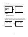
5. MENU SETUP
There are 7 categories for operation setting in the setup menu system as shown below. The following
sections will instruct you step by step to configure the operation setting and state each menu’s purpose
and options. Press the SETUP button
to access the setup menu. Once inside the menu system, the
on-screen menu allows you to set up the key features of the unit. The functions of various buttons
within the menu-setup mode are described in the paragraphs below.
MAIN MENU
TIME/ TITLE
RECORD TIMER
RECORD
ALARM
COMMUNICATION
DISK
SYSTEM
KEY FUNCTIONS
SETUP button
:
Press to enter the setup menu. Press again to exit the setup mode.
RETURN button
:
Press to exit the current setup page and return to the previous page.
Right/Left buttons
:
Press to select the desired item or entry for the setting.
Up/Down buttons
:
Press to highlight the desired option or to select the context for the setting.
ENTER
/
SAVE
ENTER/SAVE button
:
Press to enter the selected item and to save the settings.
27
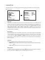
5.1 TIME/ DATE
This device is able to print inerasable system time and title information directly onto images during recording.
This page allows users to set the time and desired title, and to decide if the function is to be activated. The
entries are listed as follows.
MAIN MENU
TIME/TITLE
TIME/ TITLE
RECORD TIMER
RECORD
ALARM
COMMUNICATION
DISK
SYSTEM
TIME
TIME
TITLE
TITLE
STAMP
SETTING
STAMP
SETTING
: OFF
: SET
: OFF
: SET
MAIN PAGE
GOTO TIME/ TITLE PAGE
REC TIME STAMP
TIME STAMP:
This option determines the system time to be stamped onto the images during recording.
ON: Enables the device to stamp the time onto images during recording.
OFF: Disables the stamping function.
TIME SETTING:
This entry allows users to set the system time to be stamped onto images.
TITLE STAMP:
This option determines a programmed title to be stamped onto images during recording.
ON: Enables the device to stamp programmed title onto images while recording.
OFF: Disables the stamping function.
TITLE SETTING:
This entry allows users to assign a title to be stamped onto the images.
NOTE: If you wish to have system-time on an archived image in a floppy, the “TIME STAMP” option
must be set to “ON” for recording.
NOTE: No matter whether the “TIME STAMP” option is set to “ON” or “OFF”, the unit will always
encode the system time into the video while recording. So you can always have system time to
be displayed on the screen by pressing the “ DISPLAY” button. However, if two time messages
have overlapped on the screen, please press the “DISPLAY” button to stop decoding time from
the video so that the unit will only display the stamped time only.
28
5.2 RECORD TIMER
The DVR provides a weekly table, consisting of two periods of time each day for scheduled recording.
This option allows you to set the time each day that the DVR will start and stop recording.
MAIN MENU
RECORD TIMER
TIME/ TITLE
RECORD TIMER
RECORD
ALARM
COMMUNICATION
DISK
SYSTEM
REC ENABLE
TIMER
GOTO TIMER PAGE
TIMER REC ENABLE
: OFF
: SET
MAIN PAGE
REC ENABLE:
This option enables/disables the programmed scheduled recording.
ON: Enables the scheduled recording.
OFF: Disables the scheduled recording.
TIMER:
This entry allows users to program the time each day that the DVR will start and stop recording. There
are two time periods each day available for scheduling. The time is displayed in a 24-hour clock format.
If there is a time overlapping showing between two continual time period settings, the device will
automatically combine the two time-period settings into one combined time period setting.
REC SCHEDULE
REC SCHEDULE
START END
START END
S :06:00-16:00
12:00-18:00
START
END
S :06:00-18:00
29
START END
00:00-00:00
5.3 REC SETTING
This page allows you to set recording rate and recording quality, and to enable you to continue recording
when the disk is full.
MAIN MENU
REC SETTING
TIME/ TITLE
RECORD TIMER
RECORD
ALARM
COMMUNICATION
DISK
SYSTEM
REC RATE
REC QUALITY
DISK FULL
MULTIPLEXER
GOTO REC PAGE
SET REC RATE
: 60 F/S
: HIGH
: REWRITE
: ON
MAIN PAGE
REC RATE:
This option is for adjusting the number of pictures recorded every second into a storage disk. The
recording rate controls the frequency at which the number of video pictures can be recorded. For a
NTSC unit, there are 10 different recording rates you can select from: 60F/S (60 fields per second),
20F/S, 10F/S, 5F/S, 2.5F/S, 1.25F/S, 0.625F/S, 1 F/4S, 1F/6S, and 1F/8S. For a PAL unit, there are
two different sets of recording rates for use with a camera or a multiplexer, respectively. Please refer to
the table in section 4.1 for details.
REC QUALITY:
This option determines the image quality to be recorded. The DVR stores images in the compressed
format and allows the image quality to be altered by the image size. There are 3 levels of image quality
you can select from: HIGH, STANDARD, and BASIC. Selecting the HIGH image for use will have
higher-resolution recorded images, and normally takes up more storage space than a STANDARD or
BASIC image does.
DISK FULL:
This option determines the way to utilize storage media in case of a full disk.
REWRITE: When the hard-disk drive is full, the device continues recording by displacing the old
data.
STOP: When the hard disk drive is full, the device will stop recording.
MULTIPLEXER:
For optimum image recording please set this option to ON when the DVR connected with a multiplexer
for use. Set this option to OFF when only it is connected with a single camera.
30
5.4 ALARM SETTING
This menu allows users to program the configuration of alarm recording only when an alarm input is
activated. The device will record as long as the alarm input is activated.
ALARM SETTING
MAIN MENU
ALM OPERATION
REC RATE
REC QUALITY
ALM TYPE
ALM DURATION
PRE-ALARM
TIME/ TITLE
RECORD TIMER
RECORD
ALARM
COMMUNICATION
DISK
SYSTEM
MAIN
GOTO ALARM PAGE
: OFF
: 60 F/S
: HIGH
: NO
: NON STOP
: OFF
PAGE
ALARM REC ENABLE
ALM OPERATION:
This option determines whether to activate/deactivate the alarm recording when it detects an alarm input.
ON: The device activates the alarm recording when it detects an alarm input.
OFF: The device ignores the alarm signal when it detects an alarm input.
REC RATE:
This option is for adjusting the number of pictures recorded every second into a storage disk when an alarm
input is activated. For a NTSC unit, there are 5 different record speeds you can select from: 60F/S (60 fields
per second), 20F/S, 10F/S, 5F/S, and REMAIN. And for a PAL unit, there are 5 different record speeds you
can select from: 50F/S (50 fields per second), 25F/S, 12.5F/S, 6.25F/S, and REMAIN. If you select
REMAIN for use, the device will record images at the same speed as set on the REC page.
REC QUALITY:
This option determines the image quality to be recorded when an alarm input occurs. There are 3 levels of
image quality to choose from HIGH, STANDARD, and BASIC. The table below shows the level of image
quality with the corresponding compression ratio and image size.
ALM TYPE:
This option allows users to set a type of alarm input corresponding to the sensor signal in use.
NO: Normally Open. This is to be used with the type of alarm sensor, whose contact remain open in
normal conditions and closes in case of activation.
NC: Normally Close. This is to be used with the type of alarm sensor, whose contact remain closed in
normal conditions and opens in case of activation.
31
ALM DURATION:
This option allows users to set alarm for a certain duration. You can select one of the six following options: 0
SEC, 30SEC, 1 MIN, 5 MIN, 10 MIN, and NON-STOP.
D uration
Set ting
Alar m r ecor ding
D uration
Alar m
activated
N on-Stop
Alarm
deactivated
Alar m r ecor ding
D uration
Alar m
activated
Alarm
deactivated
R eset
PRE- ALARM:
This option determines that images prior to an alarm occurs will be recorded into the hard-disk drive. If the
alarm-recording rate is set to 60F/S, when an alarm is being triggered the device will record the image prior
to the alarm for 3 seconds. If the rest of the available alarm-recording rate is set, the pre-alarm image
recording will be extended to 5 seconds.
ON: Enables this function.
OFF: Disables this function.
32
5.5 COMMUNICATION
This option allows you to configure status of the RS-232 communication port when the connected with an
external device, and the Ethernet communications settings. (Please refer to APPENDIX 1 RS-232 Protocol
and APPENDIX 5 Network Function for more details)
MAIN MENU
COMM SETTING
TIME/ TITLE
RECORD TIMER
RECORD
ALARM
COMMUNICATION
DISK
SYSTEM
RS232
NET ENABLE
NET SETTING
MAIN
GOTO COMM PAGE
: MASTER
: OFF
: SET
PAGE
SET RS232
ON OR OFF
RS-232:
The RS-232 communication port can be in either importing or exporting mode according to your
applications.
SLAVE: Enables the RS-232 communication port to receive a signal only. When you wish the unit to
be controlled by an external device, please select this entry for use.
MASTER: Enables the RS-232 communication port to send out a signal only.
NET ENABLE:
This option is to select enable or disable the Ethernet communication port.
OFF: Disable it.
ON: Enable it.
NET SETTING:
This option is used to configure the Ethernet communication settings. This is required for making a network
connection. Please consult with a qualified MIS professional to configure it.
IP:
XXX.XXX.XXX.XXX
MASK:
XXX.XXX.XXX.XXX
GATEWAY: XXX.XXX.XXX.XXX
33
5.6 DISK SETTING
MAIN MENU
DISK SETTING
TIME/ TITLE
RECORD TIMER
RECORD
ALARM
COMMUNICATION
DISK
SYSTEM
REFORMAT
HD 3 USAGE
BACKUP
GOTO DISK PAGE
DISK REFORMAT/CLEAR
: HD 1
: BACKUP
: FULL
REFORMAT:
This option allows you to clear out all the data in the hard disk drive. You will be required to enter the pre-set
password before proceeding with clearing out the data. Enter the standard password “9999” if you don’t set
your individual password. To set your individual password, please refer to section 5.7 PASSWORD option.
HD 1: Clears out all the data stored in HD 1.
HD 2: Clears out all the data stored in HD 2.
HD 3: Clears out all the data stored in HD 3.
HD 1 2: Clears out all the data stored in HD 1 and HD 2.
HD 1 3: Clears out all the data stored in HD 1 and HD 2.
HD 123: Clears out all the data stored in HD 1, HD 2 and HD 3.
BACKUP HD: Clears out all the data stored in HD 3, which is set to backup purpose only. (This
function has to be proceeded when the HD 3 USAGE option is set to BACKUP.)
HD3 USAGE:
This option determines the way to utilize the hard-disk drive in the mobile compartment.
BACKUP: Used for data backup only, which will not be part of regular recording hard-disk drive.
REC/PLAY: Used for regular recording hard-disk drive.
NOTE: When you wish to play back a recorded video from a HD3, this option must be set to
REC/PLAY. For more details, please refer to section 4.3.4.
BACKUP:
This function allows you to duplicate data from HD 1 and HD 2 to HD 3.
(For operation details, please refer to section 4.5.1)
34
5.7 SYSTEM
This page is used for accessing the history of operation status, setting the password, resuming factory
default, and determining the menu display background.
SYSTEM
MAIN MENU
OPERATION LOG
MENU BACKGND
FLICKER REDUCT
BUZZER
PASSWORD
DEFAULT
TIME/ TITLE
RECORD TIMER
RECORD
ALARM
COMMUNICATION
DISK
SYSTEM
: ENTER
: OFF
: OFF
: ON
: SET
: LOAD
MAIN PAGE
VIEW OPERATION LOG
GOTO SYSTEM SETTING
LOG:
This log shows the history of the operation status in chronological order. What the following entries
represent is detailed below.
ON: Powers up the device.
OFF: Powers off the device.
05/15/01
05/15/01
05/15/01
05/15/01
05/15/01
05/15/01
05/15/01
05/15/01
05/15/01
REC: Starts recording.
STOP: Ceases recording.
PLAY: View recorded Video.
PAUSE: Freezes the display.
V-IN: Video input is connected.
V-LOSS: Video loss occurs.
18:19:32 ON
18:19:32 OFF
18:19:32 REC
18:19:32 STOP
18:19:32 PLAY
18:19:32 PAUSE
18:19:32 V-IN
18:19:32 V-LOSS
18:19:32 P-LOSS
P-LOSS: Power interruption occurs.
Note: The log keeps an operation history on a revolving basis because of a limit in memory
space. When the log is full, the newly registered record of an operation will replace the
existing records from the oldest one.
MENU BACKGND:
This option allows you to display the setup menu against a black background.
ON: The device displays the setup menu against a black background.
OFF: Disables this function.
35
FLICKER REDUCT:
This option allows you to eliminate the flickering condition of an image as it occurs during a playback
picture by picture or a froze image display. However, when this function is activated, the picture quality
might be degraded in a way.
ON: Enable this function.
OFF: Disable this function
BUZZER:
This option determines the embedded buzzer sounding a tone to signal the following situations. A tone
lasts about two seconds long.
ON: Enable buzzer.
OFF: Disable buzzer.
Situation
Alarm takes place
Video loss takes place
Disk is full
Load factory default
Buzzer set to ON
Enable/disable key lock function
Power on /off mobile rack HDD
Backup operation complete
Timer activate/deactivate
Recording switching between HDD
PASSWORD:
This option allows you to set a password to prevent any unauthorized re-formatting of the hard disk
drivers, and to use for network viewer. The standard password is “9999”.
OLD PASSWORD: Enter the pre-set password (or the standard password if this is the initial
setting) to access the password setting system.
NEW PASSWORD: Enter a 4-digit-number password of your choosing which will replace the
pre-set password (or the standard password “9999”).
DEFAULT:
This option allows you to reload the factory default setting.
36
6. SPECIFICATIONS
Model Number
Image System
Resolution
CL-100CD
NTSC
PAL
720 x 480 pixels
720 x 576 pixels
Video Input
BNC x 2, S-Video x 1
Video Output
BNC x 2, S-Video x 1
Storage Media
3 IDE Hard-Disk Drive (One mobile Rack)
Image Format
M-JPEG
Critical Image Archiving
Recording Rate
1.44MB FDD (JPEG)
MAX. 60 fields/sec
Image Compression
High / Standard / Basic
Recording Mode
Schedule/ Manual/Alarm/Circular
Pre-Alarm Recording
Playback Speeds
Access To Recording
MAX. 50 fields/sec
Yes
Fast Forward /Reverse:
1x, 2x, 4x, 8x, 16x, 30x,
Slow Forward/Reverse:
1/2x, 1/4x, 1/8x, 1/16x
Picture By Picture Playback
Full List Search, Time Search, and Event Search
Title
12 Characters
On Screen Display & Setup
Title / Time / Date / Setup Menu
Alarm Input
1 x NO or NC Contact Programmable
Alarm Output
1 x NO or NC Contact Programmable
Full-Disk Alarm Output
Yes
Trigger Output
1
Operation History Log
Yes
Key Lock
Yes
RS-232 port
Yes
Software Upgradable
Yes
Password Control
Yes
Ethernet
Yes
Power Interruption Recovery
Automatic Restart After Power Interruption / Recording Operation
Resume
Power Input
AC 100~240 V Input (50 Hz/60 Hz); 1 A Max
Dimensions
374 x 430 x 90 mm
5∘~ 45∘C (41∘~ 113∘F)
Operation Temperature
37
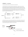
APPENDIX 1. -- RS-232 Protocol
1.Setup
1.1Use Null Modem cable (The standard RS-232 9 Pin Cable with Pin 2 and Pin 3 exchanged, see
pin configuration chart below for details) to connect the COM 1 on the rear panel of the DVR to a PC.
DVR
PC
RS-232
RS-232
1
RX 2
TX 3
4
GND 5
6
RTS 7
CTS 8
9
1
2
3
4
5
6
7
8
9
RX
TX
GND
RTS
CTS
1.2 Set the RS-232 option to MASTER in the COMMUNICATION page of the setup menu.
1.3 Set communication parameters: 9600 bps, No Parity, 8 Data Bits, 1 Stop Bit.
2. Communication Protocol:
2.0 General Command Format
<Lead Code = 0x41>, <Main category >, <Second category >, {<Number of parameters>,
<Parameter 1>, <Parameter 2> ..,} <End Code= 0x4f>
Lead Code
= 0x41
Main Category = 0x01
= 0x02
Second Category
Keys and Signals
Command
= 0x01 Handshake
= 0x02 Request Time/Set Time
= 0x05 Request System State
End Code= 0x4f
38
The different command types and their corresponding parameters are as follows:
2.1 Keys and signals
PC Send: <0x41>, <0x01>, <Key Value>, <0x4f>
< The value for a specific front panel key >
KEY_PLAY
1
KEY_STOP
3
KEY_PAUSE
4
KEY_POWER
5
KEY_REC
6
KEY_SETUP
7
KEY_ENTER
8
KEY_CANCEL
9
KEY_SEARCH
10
KEY_DISPLAY
11
KEY_UP
13
KEY_DOWN
14
KEY_LEFT
15
KEY_RIGHT
16
KEY_SCAN_F
19
KEY_SCAN_R
20
KEY_RETURN
21
KEY_MONITOR
36
2.2 COMMAND Types
2.2.0 Command (Main Category=0x02)
2.2.1 Handshake (Second Category=0x01)
PC Request: <0x41>, <0x02>, <0x01>, <0x00>, <0x4f>
DVR Response: <0x41>, <0x02>, <0x01>, <0x00>, <0x4f>
2.2.2 Request Time (Second Category=0x02)
PC Request: <0x41>, <0x02>, <0x02>, <0x00>, <0x4f>
DVR Response: <0x41>, <0x02>, <0x02>, <0x07>, <7 Time Value >, <0x4f>
The following case is an illustration of < 7 Time Value>
2001/06/20 17:05:00 = <0xD1>,<0x07>, <0x06>,<0x14>, <0x11>,<0x05>, <0x00>
39
2.2.3 Set Time (Second Category=0x02)
PC Request: <0x41>, <0x02>, <0x02>, <0x07>, < 7 Time Value >, <0x4f>
The following case is an illustration of < 7 Time Value>
2001/06/20 17:05:00 = <0xD1>, <0x07>, <0x06>, <0x14>, <0x11>, <0x05>, <0x00>
DVR Act: Changing the time and date.
2.2.4 Request State (Second Category=0x05)
PC Request: <0x41>, <0x02>, <0x05>, <0x00>, <0x4f>
DVR Response: <0x41>, <0x02>, <0x05>, <0x01>, <System State = 0..>, <0x4f>
Description of <System State>:
STATE_STOP
0
STATE_REC
1
STATE_PREREC
2
STATE_PLAY
3
STATE_MENU
4
STATE_PLAYIDLE
5
STATE_SETUP
6..16
STATE_SEARCH
7..11
STATE_BACKUP
13..15
STATE_ALARMLIST
17
STATE_LOGLIST
18
STATE_RESTART
21
2.2.5 Time Search
PC send: <0x41>, <0x02>, <0x0b>, <0x06>, <6 Bytes Date/Time>, <0x4f> where < 6 bytes
Date/Time >, = year(2 bytes, =LowByte + HighByte*256), month ( 1 byte), day (1 byte), hour(1
byte),min(1 byte)
Example: to search 06/12/2002 17:00 the Date/Time =
<0xd2>,<0x07><0x06>,<0x0b>,<0x11>,<0x00> where 2002= 210(=0xd2) + 7(=0x07) *256
NOTE: The DVR accepts RS-232 time search commands only under the live or playback
Mode.
40
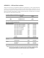
APPENDIX 2. -- IDE Hard Disk Installation
Usually, the unit comes with one hard-disk drive installed in the compartment HD 1, which is default-configured as
a master. If the unit was shipped without a hard-disk drive, please install hard disk in compartment 1 first. The
jumper settings configuration of the installed hard-disk drives for the unit and compatible drives which can be used
with this unit are listed in the table below. To install a second hard disk drive in compartment HD 2 or exchange a
larger capacity drive, please take the following steps.
The jumper settings of hard-disk drives for the system
Location
Jumper
IDE 1
Compartment HD 1
Master (Default)
IDE 1
Compartment HD 2
Slave
IDE 2
Compartment HD 3
Master
Table 3.2 B. Compatible hard-disk drives
Manufacturer
Maxtor
Model
Capacity
Diamond Max D540X-4D 4D040H2
40GB
5400 RPM
Diamond Max D540X-4D 4D060H3
60GB
5400 RPM
Diamond Max D540X-4D 4D080H4
80GB
5400 RPM
Diamond Max VL40-34098H4
40GB
5400 RPM
Diamond Max VL40-33073H3
30GB
5400 RPM
Diamond Max VL40-32049H2
20GB
5400 RPM
Maxtor 536DX 4W100H6
100GB
5400 RPM
Maxtor 536DX 4W080H6
80GB
5400 RPM
Maxtor 536DX 4W060H4
60GB
5400 RPM
Maxtor 536DX 4W040H3
40GB
5400 RPM
Maxtor 536DX 4W030H2
30GB
5400 RPM
4G120J6
120GB
5400 RPM
4G160JB
160GB
5400 RPM
IBM
DTLA-305040
40GB
5400 RPM
Quantum
Fireball Lct
20GB
5400 RPM
Fireball PlusLM
20GB
5400 RPM
ST330621A/P
30GB
5400 RPM
ST340823A/P
40GB
5400 RPM
ST380020A
80GB
5400 RPM
WD800
80GB
5400 RPM
Seagate
Western Digital
Rotation
NOTE: Hard-disk drives not shown on this list have not been tested by the engineering team
and are not recommended for use with this product. For the latest updated list on the
recommended hard disk drives, please contact your dealers or distributors
41
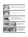
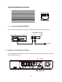
1. Unscrew all the mounting screws on the top cover of the unit and
detach it first. Unplug the interface connector and the power connector
to the drive. (Go to the next step, if there is no drive in the this
compartment.)
2. Unscrew the secured screws to detach the hard disk rack.
3. Setting the jumpers of your hard-disk drives:
The way to set the jumper of a drive varies between manufacturers;
please refer to the instructions on the drives to configure it.
Configure the drive as a slave which is located on the upper rack and
the drive as a master which is located on the lower rack.
4. Secure the drive in the rack using two
mounting screws in both the sidemounting holes. Please don’t over
tighten the screws, otherwise that may
damage the drive.
5. Attach the interface connector and the
power connector to the drive. Please
make sure that you attach the interface
connector labeled IDE Slave to the drive
in the upper rack and the interface
connector labeled IDE Master to the
drive in the lower rack.
42
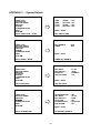
APPENDIX 3. -- System Default
MAIN MENU
TIME/TITLE
TIME
TIME
TITLE
TITLE
TIME/ TITLE
RECORD TIMER
RECORD
ALARM
COMMUNICATION
DISK
SYSTEM
GOTO TIME/ TITLE PAGE
STAMP
SETTING
STAMP
SETTING
: OFF
: SET
: OFF
: SET
MAIN PAGE
REC TIME STAMP
MAIN MENU
RECORD TIMER
TIME/ TITLE
RECORD TIMER
RECORD
ALARM
COMMUNICATION
DISK
SYSTEM
REC ENABLE
TIMER
:OFF
:SET
GOTO TIMER PAGE
TIMER REC ENABLE
MAIN MENU
REC SETTING
MAIN PAGE
TIME/ TITLE
RECORD TIMER
RECORD
ALARM
COMMUNICATION
DISK
SYSTEM
REC RATE
REC QUALITY
DISK FULL
MULTIPLEXER
GOTO REC PAGE
SET REC RATE
: 60 F/S
: HIGH
: REWRITE
: ON
MAIN PAGE
MAIN MENU
ALARM SETTING
TIME/ TITLE
RECORD TIMER
RECORD
ALARM
COMMUNICATION
DISK
SYSTEM
ALM OPERATION
REC RATE
REC QUALITY
ALM TYPE
ALM DURATION
PRE-ALARM
: OFF
: 60 F/S
: HIGH
: NO
: NON STOP
: OFF
MAIN PAGE
GOTO ALARM PAGE
ALARM REC ENABLE
43
MAIN MENU
COMM SETTING
TIME/ TITLE
RECORD TIMER
RECORD
ALARM
COMMUNICATION
DISK
SYSTEM
RS232
NET ENABLE
NET SETTING
GOTO COMM PAGE
SET RS232
: MASTER
: OFF
: SET
MAIN PAGE
MAIN MENU
DISK SETTING
TIME/ TITLE
RECORD TIMER
RECORD
ALARM
COMMUNICATION
DISK
SYSTEM
REFORMAT
HD 3 USAGE
BACKUP
: HD 1
: REC/PLAY
: FULL
GOTO DISK PAGE
DISK REFORMAT/CLEAR
MAIN PAGE
SYSTEM
MAIN MENU
OPERATION LOG
MENU BACKGND
FLICKER FILTER
BUZZER
PASSWORD
DEFAULT
TIME/ TITLE
RECORD TIMER
RECORD
ALARM
COMMUNICATION
DISK
SYSTEM
: ENTER
: OFF
: OFF
: ON
: SET
: LOAD
MAIN PAGE
VIEW OPERATION LOG
GOTO SYSTEM SETTING
44
APPENDIX 4. -- O.S.D Message
No.
O.S.D Message
Meanings
1
NO DISK
No hard disk detected after power on
2
BATTERY LOW
Suggest to change battery and reset system time
3
LOADING
System Boot up
4
VIDEO LOSS
Video loss
5
VIDEO IN n
Video input source
6
KEY LOCKED
Key lock function is on
7
KEY UNLOCKED
Key lock function is off
8
BACKUP n1 / n2 NOW
BACKUP n1/n2 NOW n3 %
9
BACKUP COMPLETE
Backup complete
10
HD3 SPACE NOT ENOUGH
HD3 has not enough space for backup
11
NO ENTRY FOR BACKUP
Nothing can be backup
12
BACKUP INCOMPLETE
13
NOT FOUND
14
END
15
DISK FULL
16
EMPTY
Backup incomplete, since user press STOP key to stop it
In Time Search function, system can not find the corresponding
video
Playback of recorded video reached end point
Hard disks are full, it happened only when the DISK FULL item in
setup menu was set to STOP
User press PLAY key or use SEARCH function, but no video could
be play.
17
SET TO NTSC, PLS RESTART
System has be set to NTSC, please reboot (PAL is similar)
18
SOFTWARE UPDATE
Software update
19
PLEASE RESTART
System should be reboot after software updated
20
NO DISK
User press save key without putting in a floppy disk, or disk error
21
DATA NOT CONTINUOUS
System finds data in installed HDs cannot be used contiguously.
Suggest to remove HD2 and HD3 from system.
22
DISK ATTACHED
HD3 was attached
23
DISK REMOVED
HD3 was removed
24
FAN STOPPED
Chassis fan stopped over 2 minutes
25
HDn ERROR AT xxxxx
26
NOT PRESENT
27
SAVE TO DISK
Start saving JPEG file
28
SAVE TO Fnnn. JPG
Save to Fnnn. JPG (where nnn= 0..999)
29
SAVE OK
Save JEPG ok
30
WRITE PROTECT
Floppy is protected or error
Hard disk error during recording, where n is hard disk number and
xxxxx is hexadecimal location.
When user try to clear a disk (in setup menu) that was not
attached
45
APPENDIX 5. -- Network Viewer, Image Viewer, and Image Convert program
This section provides instructions for installing and using the Net worker Viewer, Image Viewer, and Convert
Image, which are included with the DVR. The programs can be operated in a chosen PC equipped with the
following requirements.
1. Intel Pentium 233MHz at least.
2. 32 MB RAM
3. Window 95, 98, NT, and ME.
4. 4 MB Video card capable of 24-bit true color display.
5. 5 MB free hard-disk space for software installation.
6. 10-base T network for LAN operation.
1. The Network Viewer
1.1 Introduction to Network Viewer
The Network Viewer allows you to possibly access 16 units of the DVR from a remote desktop or a laptop over
a TCP/IP networking environment. It can perform the following functions.
View live images from the DVR
Store, search, and review recorded video from the DVR HDD.
Change regular record, event record, and timer properties.
Before ready to view images from a desktop, you need to have your DVR networked, you must obtain a 10
base Ethernet data cable (Standard RJ-45) to connect the DVR to your LAN/WAN. And then enter the
communication in the main menu to set the IP address.
RJ-45
PC
DVR
RJ-45 PIN configuration for Ethernet
PIN NO.
1.
2.
3.
4.
5.
6.
7.
8.
RJ-45 socket
PIN Assignment
TX +
TX RX +
Not Connected
Not Connected
RX Not Connected
Not Connected
12345678
46
Physical specification for Ethernet
Wire Type
Connector Type
Max. Cable Length
Hub Wiring Configuration
PC Wiring Configuration
Cat. 5
RJ-45
30 M
Straight Through
Cross Over
NOTE: For more details on network connections, please refer to APPENDIX 7
1.2 Install the Network Viewer to your PC
Install the Network Viewer from the supported CD-W.
1. Exit all applications currently running on the chosen PC.
2. Insert the supported CD to CD-ROM drive; the program will execute installation automatically and then
follow the on-screen instructions to proceed with the rest of the installation procedures when it appears.
3. After installation is complete, pop up the START menu from your computer, point to Programs/ Picture
Viewer to open up the program selection page as shown below. Click the Network Viewer tag to start the
Network Viewer program.
Install the Network Viewer for the ZIP file.
1. Save the ZIP file to your PC and extract the file to a designated directory.
2. Open the extracted folder. The folder contains 5 files.
3. Click on the
to execute installation and then follow the on-screen instructions to proceed with the
rest of the installation procedure when it appears.
4. After installation is complete, pop up the START menu from your computer, and point to Programs/
Picture Viewer to open up the program selection page as shown below. Click the Network Viewer tag to
start the Network Viewer program.
NOTE: Please make sure the TCP/IP communication software has been properly set and configured in
your computer. To check your TCP/IP settings, refer to APPENDIX 7
47
1.3 View DVR Video From A Remote PC
Follow the instructions below to use the Network Viewer to browse a DVR video from a remote location.
Upon entering the Network Viewer; the connection box will appear as follows.
1. Choose a channel number from the Channel drop-down list.
2. Assign a name for the chosen DVR.
3. Type in the password and IP of the device and click Add tag to add the device to the connection list.
4. Click the Connect tag to establish the connection between devices and the computer. To begin viewing
images, click OK.
NOTE: Upon connection, the connection status box indicates the name and IP address of the
selected device. If unable to connect, a “Fail” message appears on the screen right after the
device IP address; otherwise an “OK” appears. To add more connections or units of the DVR,
please repeat the above instructions.
Functions
Channel
Name
Password
URL of the Remote Device
URL of a Proxy
Port
Modify
Delete
Connect
OK
Cancel
Description
Assign a display location when you have multiple devices connected.
This box allows you to assign a name to the chosen device.
Type the preset password for making a connection.
Type the IP address which you preset for the device
Type your proxy server address when accessing the Internet via a proxy
server.
Enter the designated port setting of your proxy server.
Click to change the settings of a chosen device.
Click to remove the connection of a chosen device
Click to establish the connection between devices and the computer.
Click to access the display page of the Network Viewer
Click to exit the program of the Network Viewer.
48
Viewing images
View all the connected devices
Once the connection has been established, click OK to enter the Multi-device mode window. (See the
sample screen below) This window displays all the connected devices in sequence which has been
arranged when you established the connection.
Function Buttons
Description
Split-Screen display function bar. This allows you to display the connected
device in a multi-format screen 1, 2x2, 3x3, and 4x4.
Press to enter the selected device (Single device display mode) Select a
device from the DEVICE LIST box to enable this button.
Press to open the device setting page to add more devices for viewing.
Press to leave the Network Viewer program.
Connected devices display box. This box indicates the title and IP
address of all connected devices.
Device title and image display area. Display the title of each connected
device and the time/day information of each displayed image on the top
blue bar.
49
View single device
Follow either of the following instructions to get into the single device mode.
1. Select the desired device from the DEVICE LIST box on the Multi-device Mode. The
button will
enable. Click the button to view the image of the selected device and have access to certain functional
operations of the device via the network. (See the sample screen below.)
2. Double click the image display area of each screen.
50
Function Buttons
Description
Playback function bar.
Play- Click to a recorded video from the PLAY LIST.
Pause- Click to freeze the image.
Stop- Click to stop playing back the recorded video or cease recording.
REC- Click to activate recording function of the device.
Step- Click to view images picture-by-picture.
Click to return to the Multi-Device mode.
Click to save a viewing image into the local computer.
Click to enter the SETUP page, which allows you to program the recording
time, recording quality, and schedule recording.
Click to exit the Network Viewer program.
Multiplexer format list box.
Select a MUX from the drop-down list that is connected with the DVR, so the
Network Viewer will be able to display cameras in corresponding to the
camera input of the Multiplexer. If your MUX isn’t available, please select the
Others option for use. The Viewer will display cameras in thumbnail format.
(Sequentially displaying images one after another in the adjacent display
window)
Recorded video list box. This box allows you to access all recorded video,
which are stored in the HDD of the connected devices. To review a recorded
button.
video, just click a entry from the list and click the
PgUp/PgDn: To scroll up and down the list.
DVR Status Box. This box indicates the selected device status.
PLAY: The device is in the playback mode.
LIVE: The device is in the live display mode.
WAIT: The device is processing the command.
PAUSE: Pause the image.
This allows you to search a recorded video kept in the HDD of the device.
Enter the MONTH/DAY/YEAR HOUR: MINUTE you wish to search and click
GO to proceed.
Split-Screen display function bar. This allows you to display the selected
device in a multi-format screen 1, 2x2, 3x3, and 4x4.
Image display area. Display the images of each camera and the title and
time/date information on the top blue bar. Double click the image to view a full
screen of the camera.
51
1.4 Change the Record & Timer Properties Via the network
Follow the instructions below to reconfigure the record and schedule recording settings via the network.
A.
Set the regular record settings
1. When in the single –device mode, click
to enter SETUP page. (See the sample screen as above A)
2. Select a desired recording rate and Quality from the respective drop-down list
3. Click the OK tag to proceed.
Set the Alarm record settings
1. When in the single –device mode, click
to enter SETUP page. (See the sample screen as above A)
2. Set the ALRM SETTING to ON to enable the drop-down list in the ALARM SETTING area.
3. Select a desired recording rate and Quality from the respective drop-down list.
4. Click the OK tag to proceed.
Set the record timer
1. When in the single –device mode, click
to enter SETUP page. (See the sample screen as above A)
2. Set the RECORD TIMER to ON to enable the RECORD TIMER setting area. All of MODIFY button will appear.
3. Click the MODIFY button to set the schedule for recording for each day. (See the sample screen below)
Enter in both the START TIME & END TIME boxes a specific Hour: Minute and click OK to return to the
SETUP page.
4. When all required settings are done, click OK to proceed.
52
1.5 Archive Images To The Computer
Single live or playback images can be stored into a local PC in the JPEG format. Follow the following
instructions to save the viewed images to your PC.
1. Press
to enter the following sample screen whenever in the live or playback mode.
2. Select a folder on the computer for copying images in.
3. Enter the number of images into the NUMBER OF SAVING box you wish to save.
4. Click the SAVE tag; the program will automatically copy the displayed images into the designated folder. The
images are saved in the DVRxxx.jpg file name, which are displayed in the on lower-right box. To view a
saved image, please follow the instructions in the next section to proceed.
53
2. View a still JPEG image
This is image integrity-protect software. It doesn’t only allow you to view an archived image from a floppy or
a HDD of a computer, but to also protect an archived image from reproduction or interpolation. If an image
isn’t in the original format made by a DVR, the Image Viewer will not display the image and instead send a
warning message” Wrong File, Can’t Open”. Follow the following instructions to open an archived image
from a floppy disk or a HDD.
1. Pop up the START menu from your computer, and point to Programs/Picture Viewer to open up
the program selection page. Click the Image Viewer tag to start the Image Viewer program. (See a
sample screen below.)
2. Select a folder where the files are kept and click on a file you wish to display from the upper-right
box or click on the AUTOPLAY tag to display automatically all the files in the selected folder. Each
file will be displayed for 2 seconds on the screen.
3. Click the PRINT tag to get a displayed image printed out from a printer.
4. If you wish to transfer a displayed image into a 720x480 format, click the SAVE 720x480 to proceed.
54
3. Convert Image Program
This program allows you to convert archived images into a 720x480 format, which allows you view the archived
images via a computer with a JPEG compatible program. Please follow the instructions below to proceed.
1. Pop up the START menu from your computer, and point to the Programs/Picture Viewer to open up the
program selection page. Click the Convert Image tag to start the Convert Image program. (The Image
Viewer is shown as a sample screen below.)
2. Click the
tag to select a folder where files are kept you wish to convert from the Source Path box.
3. Click the
tag to select a folder where you wish to convert files in from the Destination Path box.
4. Click the Transform[T] tag to proceed.
5. Click the Cancel[C] tag to stop processing at any time while converting.
55
APPENDIX 6. -- Index Table
The following description details how the DVR manages an index table issue.
The DVR will generate a time index table indicating recorded data kept in a respective HDD. This allows to
individually select record data to be displayed via alarm list search and full list search. The maximum number of
lists, for a respective HDD, is 2015. When the list of any given HDD is used up and the disk is not full, for a new
recording the unit will still use the rest of the space for recording. In such a case, an index for the recent recorded
data will be generated and the index of the next oldest data will be erased so that the list in total does remain
2015. And the next oldest data should be kept under the index of the oldest data. For any new-recorded data, this
approach will be applied until the disk becomes full.
HD1
HD1
1
2002-02-01 12:20
1
2002-02-01 12:20
2
2002-02-01 13:30
2
2002-03-01 16:00
3
2002-03-01 16:00
2015 lists
.
.
.
.
.
2015 2002-03-04 16:00
2015 lists
.
2014
2002-03-04 16:00
2015
2002-08-01 17:30
In the rewrite recording mode, when the archived hard disk drive is full, the DVR will start overwriting the oldest
data recorded. As a previous recorded data was partially overwritten by a recent recording, the indicating time
index of that data will be changed corresponding to the starting time of the session remaining. The index of the
session should be dismissed from the table when it is fully overwritten.
Previously
recorded data
overwritten
The point stops recording
Previously recorded data remaining
56
APPENDIX 7 -- Network Configuration
1. Cable Connections
Please follow the instructions below to connect your DVR to a computer or a network and to choose a proper
RJ-45 cable configuration for connections.
Physical specification of RJ-45 cable for Ethernet
Wire Type
Cat. 5
Connector Type
RJ-45
Max. Cable Length
30 M
Hub Wiring Configuration
Straight Through
PC Wiring Configuration
Cross Over
1.1
Connect With A Computer
6
5
4
ALM.RST
REC
7
ALM. IN
8
GND
9
DISK FULL
ALM.OUT
S-VIDEO
GND
VIDEO
IN
SW.OUT
MUX MAIN
MONITOR
GND
For connecting directly to a computer, use a crossover LAN cable.
3
2
1
This device complies with
part 15 of the FCC Rules.
Operation is subject to the
following two conditions:
(1) This device may not cause
harmful interference. And
(2) this device must accept
any interference received,
including interference that
may cause undesired operation.
OUT
CROSSOVER CABLE
PIN CONFIGURATION
RJ45
CROSSOVER CABLE
TO PC LAN CARD
Connect with a LAN Hub (INTRANET)
5
4
ALM. IN
6
ALM.RST
7
GND
8
REC
9
DISK FULL
S-VIDEO
GND
VIDEO
IN
ALM.OUT
MUX MAIN
MONITOR
SW.OUT
The RJ-45 PIN configuration for connecting with a LAN Hub is shown as below.
GND
1.2
3
2
1
This device complies with
part 15 of the FCC Rules.
Operation is subject to the
following two condit ions:
(1) This device may not cause
harmful interference. And
(2) this device must accept
any interference received,
including interference that
may cause undesired operation.
TO PC LAN CARD
OUT
RJ45
TO NETWORK
1
2
3
4
HUB
57
uplink
RJ-45 PIN configuration for LAN Hub
PIN NO.
1.
2.
3.
4.
5.
6.
7.
8.
1.3
PIN Assignment
TX +
TX RX +
Not Connected
Not Connected
RX Not Connected
Not Connected
RJ-45 socket
12345678
Connect with WAN (INTERNET)
The RJ-45 PIN configuration for connecting with a WAN is the same as connecting with a LAN.
5
4
ALM.RST
6
ALM. IN
7
REC
8
GND
9
DISK FULL
ALM.OUT
S-VIDEO
GND
VIDEO
IN
SW.OUT
MUX MAIN
MONITOR
GND
Cable/xDSL modem
3
2
1
This devic e complies with
part 15 of the FCC Rules.
Operation is subject to the
following two conditions:
(1) This device may not cause
harmful interference. And
(2) this device must accept
any interference received,
including interference that
may cause undesired operation.
LAN
WAN
OUT
RJ45
TO ISP
2 Configure Your DVR Network Settings
Upon network hardware connection, you need to activate the network function and configure the proper
network settings of the DVR.
RETURN
SETUP
STOP
SETUP
DISPLAY
SEARCH
RETURN
PLAY
REW
FWD
ENTER
/
SAVE
REC
MONITOR
MUX
DVR
58
PAUSE
/
STEP
2.1 Enable DVR Network Function
Press the SETUP button to enter the OSD MAIN MENU. Please use the
to highlight COMMUNICATION; then press the
ENTER
/
SAVE
Right / Left buttons
ENTER/SAVE button to enter the COMM
SETTING page.
Up / Down buttons to highlight NET ENABLE; select ON. Then press the
Use the
ENTER
/
SAVE
ENTER/SAVE button to proceed.
MAIN MENU
COMM SETTING
TIME/ TITLE
RS232
: MASTER
RECORD TIMER
RECORD
ALARM
COMMUNICATION
DISK
SYSTEM
NET ENABLE
NET SETTING
: ON
: SET
MAIN
PAGE
SET NET ENABLE ON OR OFF
GO TO COMM PAGE
2.2 Set IP Address
Up / Down buttons to highlight NET SETTING. And press the
Use the
ENTER
/
SAVE
ENTER/SAVE
button to enter the NET SETTING page
Set IP, MASK and GATEWAY. Then press the
ENTER
/
SAVE
ENTER/SAVE button to proceed. Press the
RETURN button to return to the MAIN MENU. The following is a sample settings.
IP:
192.168.0.1
MASK:
255.255.255.0
GATEWAY:
0.0.0.0
MAIN MENU
COMM SETTING
TIME/ TITLE
RS232
: MASTER
RECORD TIMER
RECORD
ALARM
COMMUNICATION
DISK
SYSTEM
NET ENABLE
NET SETTING
: ON
: SET
MAIN
PAGE
SET NET SETTING ON OR OFF
GO TO COMM PAGE
59
NOTE: When only one unit of the DVR is connected with a computer or LAN, you can freely assign
an IP address for the DVR. For example, there is a range of DVR IP addresses from
192.168.0.1 to 192.168.0.255. You can pick one for use from the range of IP. It’s not necessary
to set MASK and GATEWAY; leave the settings as default.
When a DVR is connected to a WAN, you must acquire a unique, permanent IP address and
correctly configure the MASK and GATEWAY settings according to your network architecture.
If you have any questions regarding those settings, please contact a qualified MIS
professional or your ISP.
NOTE: When connecting with a network, each connected DVR must be assigned a unique IP, which
must be in the same class type as your network address. IP addresses are written as four
sets of numbers separated by periods; for example, 314.278.74.8. Therefore, if the connected
network is identified as Class C, for example, the first three sets’ numbers of the DVR IP
address must be the same as the network address. If the connected network is identified as
Class B, the first two sets’ numbers of the DVR IP address must be the same as the network
address. If you have any questions regarding those settings, please contact a qualified MIS
professional or your ISP.
3 TCP/IP Communication Software
Follow the instructions below to install the TCP/IP communication program into your computer.
Click the Start Menu from your computer, and point to the Settings/Control panel.
60
Click the NETWORK icon twice to enter the NETWORK setting windows.
Click on the Configuration tag; check if the TCP/IC is included among the network components list.
If the TCP/IP is included, please process step 5. If it is not included, please follow step 4 to install
the TCP/IP.
61
4. TCP/IP installation
During the installation, you will be requested to insert the windows 98 CD ROM. After installation, the PC
will be restarted.
5.
TCP/IP Configuration setting
Click Start
Settings
Control Panel
Network.
Select TCP/IP, and then click Properties.
Before processing the DVR installation in a WAN, please make sure the Internet connection works
properly. If not, please contact your ISP provider.
62
If you are using a DHCP server, please select Obtain an IP address automatically. Any assigned IP
address for the connected DVRs must be in the same class type as the server. If there is no DHCP server,
please select specify an IP address and type in the IP address of your PC. This IP address must be
different from the DVR IP but in the same class type.
NOTE: The IP address of a DVR in a network must be unique to other chosen PCs’ but in the same
class type.
6. Connection Testing
With the previous settings, follow the instructions below to insure whether you have established the
connection successfully.
Click Start
Programs
MS-DOS Prompt
Type in ping 192.168.0.1 then Enter. (See sample screen below)
** This IP is the DVR IP address which is assigned for the connected DVR in step 2.
63
If you receive a response as in the sample screen below, the connection hasn’t been successfully
established. Please re-check all the hardware and software installation by repeating steps 1 to 5. If you
still can’t establish the connection after rechecking, please contact your dealer.
If you receive a response as in the sample screen below, you have successfully built the connection.
RMN040200110
64