1
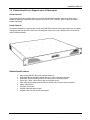
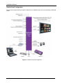
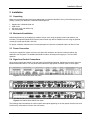
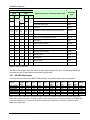
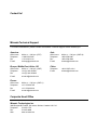
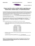
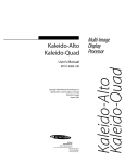
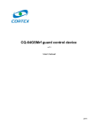
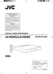
Kaleido-Alto
Kaleido-Quad
Multi-Image Display Processor
Installation Manual
M791-4200-104
5 September 2008
Miranda
Technologies Inc.
3499 Douglas-B.-Floreani
St-Laurent, Québec, Canada H4S 1Y6
Tel. 514-333-1772
Fax 514-333-9828
www.miranda.com
© 2008 Miranda Technologies Inc.
Installation Manual
Safety Compliance Information
Safety Compliance
This equipment complies with:
-
CSA C22.2 No. 60950-1-03 / Safety of Information Technology Equipment, Including Electrical Business Equipment.
UL 60950-1 (1st Edition) / Safety of Information Technology Equipment, Including Electrical Business Equipment.
st
IEC 60950-1 (1 Edition) Incorporating A1, A2, A3, A4, and A11/ Safety of Information Technology Equipment, Including
Electrical Business Equipment.
CAUTION
These servicing instructions are for use by qualified service personnel only. To reduce the risk of electric shock, do not
perform any servicing other than that contained in the operating instructions unless you are qualified to do so. Refer all
servicing to qualified service personnel. Servicing should be done in a static-free environment.
Kaleido-Alto & Kaleido-Quad
Installation Manual
Table of Contents
1 Kaleido-Alto & Kaleido-Quad ....................................................................................... 1
1.1 Introduction .............................................................................................................................................. 1
1.2 Kaleido-Alto Series: Supports up to 10 Video Inputs............................................................................... 1
1.3 Kaleido-Quad Series: Supports up to 4 Video Inputs .............................................................................. 3
2 Installation ..................................................................................................................... 5
2.1 Unpacking ................................................................................................................................................ 5
2.2 Mechanical Installation............................................................................................................................. 5
2.3 Power Connection.................................................................................................................................... 5
2.4 Signal and Control Connections .............................................................................................................. 5
2.4.1 HD-SDI Video Inputs ......................................................................................................................... 6
2.4.2 SD-SDI Video Inputs ......................................................................................................................... 7
2.4.3 Composite Video Inputs .................................................................................................................... 7
2.4.4 DVI Input............................................................................................................................................ 7
2.4.5 DVI Resolutions Supported with a KXI-DVI-Bridge Connected to the Kaleido’s HD-SDI Input ........ 8
2.4.6 Analog Audio Inputs (Optional Alto-SA Mezzanine with 10 or 4 Inputs) ........................................... 9
2.4.7 Digital Audio Input (Optional Alto-AES Mezzanine) .......................................................................... 9
2.4.8 PC Audio Input ................................................................................................................................ 10
2.4.9 Component Analog (RGBHV) Output.............................................................................................. 10
2.4.10 DVI Output....................................................................................................................................... 10
2.4.11 Audio Monitoring Output.................................................................................................................. 11
2.4.12 GPI Inputs /Outputs ......................................................................................................................... 11
2.4.13 Ethernet ........................................................................................................................................... 13
2.4.14 USB ................................................................................................................................................. 13
2.5 Dual power supplies (Optional).............................................................................................................. 13
2.6 Multiple Kaleido-Alto/Quad Installations ................................................................................................ 14
2.6.1 Ethernet Connection for use with KEdit........................................................................................... 14
2.6.2 Controlling Multiple Kaleido-Alto/Quad units from a Kaleido-RCP.................................................. 14
3 Operation ..................................................................................................................... 16
3.1
3.2
3.3
3.4
Powering Up........................................................................................................................................... 16
Front Panel Status LED ......................................................................................................................... 16
Startup and Preparation......................................................................................................................... 16
Software Installation............................................................................................................................... 16
4 Technical Specifications ............................................................................................ 17
4.1
4.2
4.3
4.4
4.5
Inputs ..................................................................................................................................................... 17
Outputs................................................................................................................................................... 18
Control.................................................................................................................................................... 19
Processing Performance........................................................................................................................ 20
Frame..................................................................................................................................................... 20
Annex – Kaleido Display Resolution .............................................................................. 21
Contact Us! ....................................................................................................................... 23
Kaleido-Alto & Kaleido-Quad
1 Kaleido-Alto & Kaleido-Quad
1.1 Introduction
The Kaleido-Alto and Kaleido-Quad multi-image processors can display multiple video inputs (up to 10 for the
Alto, up to 4 for the Quad) on a single high-resolution output. The Kaleido-Alto/Quad combines the display of
video windows, audio level meters, text identification labels, tallies and on-screen status indicators in a
convenient single-RU frame. Various models are offered to support SDI video, composite video or the autodetection of composite and SDI. Four stereo audio level meters can be displayed inside or outside each video
window. Audio sources can be extracted from the embedded audio inside the SDI signals, or input via optional
audio mezzanines providing 4 or 10 AES or Analog stereo input signals. A DVI input allows the insertion of an
external computer signal to fill the background of the video layout. Layouts can be created using the KEdit
layout editor software and applied to the Kaleido-Alto/Quad system afterward. Layouts and frequently-used
functions can be operated via the Kaleido-RCP or via a mouse/pointer interface. The Kaleido-Alto/Quad is an
ideal solution in areas where a limited number of signals need to be monitored with fine picture quality. Its
compact 1RU frame is a real asset in areas where space is restricted.
The Kaleido-Alto/Quad is available in several different models:
1.2 Kaleido-Alto Series: Supports up to 10 Video Inputs
Kaleido-Alto-HD
The Kaleido-Alto-HD is configured with 10 auto-detect HD/SD-SDI/Composite video inputs. Each input is
capable of displaying HD/SD-SDI and Composite video input in PAL, SECAM, NTSC or black-and-white
formats automatically.
Kaleido-Alto-AD
The Kaleido-Alto-AD is configured with 10 auto-detect SD-SDI/Composite video inputs. Each input is capable of
displaying SD-SDI with 525 or 625 lines and Composite video input in PAL, SECAM, NTSC or black-and-white
formats automatically.
Kaleido-Alto-A
The Kaleido-Alto-A offers 10 Composite inputs. Each input auto-detects PAL, SECAM, NTSC or black-andwhite formats.
Installation Manual
Kaleido-Alto Features
•
•
•
•
•
•
•
•
•
Auto-sensing HD-SDI, SDI and Analog Composite inputs (10)
High-quality DVI and RGBHV outputs with up to 1920 x 1080 pixel resolution (except Kaleido-Alto-A and
Kaleido-Alto-AD models, which are limited to 1280 x 1024)
Embedded, AES and Analog audio level metering with monitoring outputs
Source IDs, Tallies, clocks (time of day and up/down timers)
Easy offline layout editing with full choice of window ratio (4:3 and 16:9) and position
Aspect ratio markers
Compact (1RU) frame
Optional redundant power supply
Optional, simple to use remote control panel
Kaleido-Alto Configuration
Here is a typical configuration for a Kaleido-Alto, in this case illustrating an Alto-AD.
Figure 1.1 Kaleido-Alto-AD configuration
2 | Kaleido-Alto & Kaleido-Quad
Installation Manual
1.3 Kaleido-Quad Series: Supports up to 4 Video Inputs
Kaleido-Quad-HD
The Kaleido-Quad-HD is configured with 4 auto-detect HD/SD-SDI/Composite video inputs. Each input is
capable of displaying HD/SD-SDI and Composite video input in PAL, SECAM , NTSC or black-and-white
formats seamlessly.
Kaleido-Quad-AD
The Kaleido-Quad-AD is configured with 4 auto-detect SD-SDI/Composite video inputs. Each input is capable
of displaying SD-SDI with 525 or 625 lines and Composite video input in PAL, SECAM, NTSC or black-andwhite formats seamlessly.
Kaleido-Quad Features
•
•
•
•
•
•
•
•
•
Auto-sensing HD-SDI, SDI and Composite inputs (4)
High quality DVI and RGBHV outputs with up to 1920 x 1080 pixel resolution
Embedded, AES and Analog audio level metering with monitoring outputs
Source IDs, Tallies, clocks (time of day and up/down timers)
Easy offline layout editing with full choice of window ratio (4:3 and 16:9) and position
Aspect ratio markers
Compact (1RU) frame
Optional redundant power supply
Optional, simple to use remote control panel
Kaleido-Alto & Kaleido-Quad | 3
Installation Manual
Kaleido-Quad Configuration
Here is a block diagram showing a typical configuration for a Kaleido-Quad, in this case illustrating a Quad-AD
system.
Figure 1.2 Kaleido-Quad-AD configuration
4 | Kaleido-Alto & Kaleido-Quad
Installation Manual
2 Installation
2.1 Unpacking
Make sure the following items have been shipped with your Kaleido-Alto/Quad. If any of the following items are
missing, contact your distributor or Miranda Technologies Inc.
•
•
•
•
Kaleido-Alto or Kaleido-Quad unit
USB mouse
AC power cord, and retainer clip
CD with software
2.2 Mechanical Installation
Kaleido-Alto/Quad may be installed in a standard 19-inch rack, using the proper screws and washers ( not
included). The optional Kaleido-RCP Remote Control Panel may also be installed in a rack using the optional
mounting kit (order part #1229-1100-100).
For proper ventilation, make sure the front and side panel air vents are not blocked and the air filter is clean.
2.3 Power Connection
Connect the supplied AC power cord to the rear-panel AC receptacle, and secure it with the retainer clip
attached to the receptacle. The Kaleido-Alto/Quad includes a universal power supply for 110V and 220V
operation.
2.4 Signal and Control Connections
All inputs and outputs are located on the rear panel of the Kaleido-Alto/Quad. Signals and connector types are
listed and described below. The rear panel labels indicate the appropriate connection point for each signal.
Figure 2.4.1 Kaleido-Alto-AD/A rear panel
Figure 2.4.2 Kaleido-Alto-HD rear panel
Figure 2.4.3 Kaleido-Quad-HD/AD rear panel
The following chart summarizes the various inputs and outputs appearing on the rear panels of these units, and
is followed by a discussion of each of the connections.
Kaleido-Alto & Kaleido-Quad | 5
Installation Manual
Kaleido
Quad
AD
4
Signal connections & communication ports
Alto
HD
A
4
10
AD
HD
10
10
Connector
type
HD-SDI video inputs
BNC
SD-SDI video inputs
BNC
Composite video inputs
BNC
DVI input
DVI-D
AES/EBU or stereo analog audio input (optional)
DB-44S
1
1
1
1
1
4 or
10
4 or
10
4 or
10
4 or
10
4 or
10
1
1
1
1
1
PC audio input
3.5 mm jack
1
1
1
1
1
Component analog (RGBHV) output
DE-15P
1
1
1
1
1
DVI output
DVI-I
1
1
1
1
1
Audio monitoring output
DE-15P
20
20
20
20
20
GPI inputs
DB-44S
10
10
10
10
10
GPI outputs
DB-44S
1
1
1
1
1
Ethernet communication
RJ-45
1
1
1
1
1
RS-422 A port
DE-9
1
1
1
1
1
RS-232 port
DE-9
1
1
1
1
1
RS-422 B port
DE-9
2
2
2
2
2
Mouse and Keyboard
USB type A
Table 1: Signal connections
Note that one set of BNC connectors serves all video inputs except the DVI input. The Kaleido-Alto/Quad will
auto-detect the type of signal applied, and process it appropriately.
2.4.1 HD-SDI Video Inputs
These inputs must conform to the SMPTE 292M standard. The following input formats are supported:
Format
1080i 59.94Hz
1080i 50Hz
720p 59.94Hz
720p 50Hz
1080p 29.97Hz
1080p 23.98Hz
Display
Aspect
Ratio
16:9
16:9
16:9
16:9
16:9
16:9
Active
Pixel
Active
Lines
Total
Pixels
1920
1920
1280
1280
1920
1920
1080i
1080i
720
720
1080
1080
2200
2376
1650
1980
2200
2750
Total
Lines
1125
1250
750
750
1125
1125
Pixel
Aspect
Ratio
SQR
SQR
SQR
SQR
SQR
SQR
Scan
Form.
2:1
2:1
1:1
1:1
1:1
1:1
Frame
Rate
(Hz)
29.97
25
59.94
50
29.97
23.98
Line
Rate
(KHz)
33.72
31.25
44.96
37.5
33.72
26.97
Pixel
Rate
(MHz)
74.18
74.25
74.18
74.25
74.18
74.18
Std.
(SMPTE)
274M
295M
296M
296M
274M
274M
Make sure the input cable has a maximum length of 100m (325') (Belden 1694) and that all serial digital video
connections are point-to-point. For instance, there must be a point-to-point connection between the IN BNC and
the source equipment. If a T-connector is used to connect other equipment, the maximum specified cable
length is no longer valid.
6 | Kaleido-Alto & Kaleido-Quad
Installation Manual
2.4.2 SD-SDI Video Inputs
The inputs are on BNC connectors and accept 4:2:2 serial digital video signals in either 525 or 625-line format.
These inputs must conform to the SMPTE 259M-C standard.
Make sure the input cable has a maximum length of 225m (730’ using Belden 1694A), and that all serial digital
video connections are point-to-point. For instance, there must be a point-to-point connection between the IN
BNC and the source equipment. If a T-connector is used to connect other equipment, the maximum specified
cable length is no longer valid.
2.4.3 Composite Video Inputs
The inputs are BNC connectors, internally terminated and accept NTSC, PAL, SECAM and monochrome
(B&W) video signals. NTSC-M signals must conform to the SMPTE 170M standard and PAL (625/50), PAL-M
(525/60) signals must conform to the ITU-R BT.470-6 standard.
2.4.4 DVI Input
A DVI signal may be connected to the Kaleido-Alto/Quad to provide a background image behind the monitoring
windows. Supported DVI signal resolutions are shown in the table 2 below
Note: To use a background image from a source connected through the DVI input, you must make sure that
the source computer and your Kaleido’s display screen are configured to the same resolution, since no scaling
will be applied to the DVI input signal.
Alternatively, a KXI-DVI-Bridge device can be connected upstream to the Kaleido-Alto/Quad in order to provide
a scaled background image. See section 2.4.5 “DVI Resolutions Supported with a KXI-DVI-Bridge Connected
to the Kaleido’s HD-SDI Input” for details.
Kaleido
Quad
Alto
Resolution
Scanning
format
Line rate
(kHz)
Frame rate
(Hz)
AD
HD
A
AD
HD
X
X
X
X
X
800
x 600
Progressive
37.7/31.4
59.94
50
X
X
X
X
X
1024
x 768
Progressive
48.4/40.3
59.94
50
X
X
X
X
X
1280
x 768
Progressive
48.1/40.1
59.94
50
X
1280
x 1024
Progressive
64/53.3
59.94
50
X
1360
x 768
Progressive
47.6/39.8
59.94
50
X
X
X
X
X
X
(H
x
V)
X
X
X
X
X
1600
x 1200
Progressive
74,9/62.5
59.94
50
X
X
X
1920
x 1080
Progressive
69.5/62.5
59.94
50
Table 2 Supported DVI input signal resolutions
Note that the 1600X1200 and 1920X1080 formats apply only to selected models, and that special consideration
is required when using them. See the “Annex – Kaleido Display Resolution” for more information.
Kaleido-Alto & Kaleido-Quad | 7
Installation Manual
2.4.5 DVI Resolutions Supported with a KXI-DVI-Bridge Connected to the Kaleido’s
HD-SDI Input
With a KXI-DVI-Bridge device connected between a computer’s DVI output and the HD-SDI input of a KaleidoAlto-HD or Kaleido-Quad-HD, the following resolutions are supported.
Without dongle:
DVI resolution
HD-SDI output
1024x768 (XGA), 60 Hz
1280x1024 (SXGA), 60 Hz
1366x768 (WXGA), 60 Hz
1080i @ 29.97 Hz
Suitable for graphic-type
images with slow
motion.
1680x1050 (WSXGA+), 60 Hz
With dongle:
DVI resolution
HD-SDI output
1280x720, 50 Hz
720p, 50 Hz
1280x720, 60 Hz
720p, 60 Hz
1920x1080, 50 Hz
1080i, 50 Hz
1920x1080, 60 Hz
1080i, 60 Hz
8 | Kaleido-Alto & Kaleido-Quad
Best-quality
performance with videotype computergenerated content. No
motion artifacts.
Installation Manual
Note: The KXI-DVI-Bridge’s input can be static content (such as computer-generated text and static graphics)
to be scaled and merged against the layout background on the Kaleido. In this case the dongle is generally not
required. For the KXI-DVI-Bridge to process dynamic content (such as streaming video or computer-generated
animations), the dongle is required. Please refer to your KXI-DVI-Bridge User’s Manual for more information.
2.4.6 Analog Audio Inputs (Optional Alto-SA Mezzanine with 10 or 4 Inputs)
This option provides inputs for 10 or 4 channels of analog stereo audio. Two DB-44S connectors are available
on the Alto-SA mezzanine.
Connect balanced analog stereo audio signals to the audio input connectors. Each connector receives 5 stereo
inputs (refer to figure 2.4.4 below for connector pinout). For the 4-input audio version only inputs IN 1-4 are
available.
To facilitate cabling of the audio inputs, a terminal block adapter is available separately (Alto-TBA-AG). A Lexan
plate is provided to identify the terminal assignment for the input connectors. See figure 2.4.6 for plate
installation on the Alto-TBA-AG terminal block adapter.
Figure 2.4.4 Analog audio connector pinout
2.4.7 Digital Audio Input (Optional Alto-AES Mezzanine)
This option provides inputs for 10 or 4 channels of AES/EBU digital audio. A single DB-44S connector is
available on the Alto-AES mezzanine.
Connect AES balanced audio signals to the audio input connector. Signal must conform to AES3-1992/ANSI
S4.40-1992 standard. The DB-44 connector receives 10 inputs (refer to figure 2.4.5 below for connector
pinout). For the 4-input audio version only inputs IN 1-4 are available.
To facilitate cabling of the audio inputs, a terminal block adapter is available separately (Alto-TBA-AG). A Lexan
plate is provided to identify the terminals assignment for the input connectors. See figure 2.4.6 for Lexan plate
installation on the Alto-TBA-AG terminal block adapter.
Kaleido-Alto & Kaleido-Quad | 9
Installation Manual
Figure 2.4.5 AES-EBU connector pinout
Figure 2.4.6 Installing the Lexan plate on Alto-TBAAG
2.4.8 PC Audio Input
Connect a 3.5 mm audio jack to provide an analog stereo audio input coming from a personal computer. Note
that this audio signal is input at its nominal level, which is controlled by the originating computer. Make sure that
the level is within specifications (see section 4 “Technical Specifications”) by adjusting the level on the
originating computer.
2.4.9 Component Analog (RGBHV) Output
Analog progressive scan component video output (DE-15P connector). Connector pinout is shown in figure
2.4.7 below.
Figure 2.4.7 DE-15P connector pinout
2.4.10 DVI Output
Digital progressive scan component output (DVI digital connector), with resolutions as shown in the chart on
page 7 for the DVI input.
For optimum performance, good DVI cables should be used. For instance, cable model D-766 from Cable4PC
(www.cable4pc.com) is recommended.
10 | Kaleido-Alto & Kaleido-Quad
Installation Manual
2.4.11 Audio Monitoring Output
A DE-15P connector is provided to monitor one stereo audio channel, in both balanced AES3 and analog
formats. Refer to figure 2.4.8 for connector pinout.
Figure 2.4.8 Audio monitoring connector pinout
2.4.12 GPI Inputs /Outputs
The GPI input connector provides interfaces and processing to support 20 contact closure tally inputs and
provisions to support 10 outputs using DB-44S connectors. The connector pinout and circuit schematics are
shown in figure 2.4.9 and 2.4.10 below.
To facilitate cabling of the GPI inputs and outputs, a terminal block adapter is available separately (Alto-TBAAG). A double-sided Lexan plate is provided to identify the terminals assignment for both input and output
connectors. Place the Lexan plate as indicated in figure below, and install cables and plug the adapter into the
connector.
Figure 2.4.9 GPI Connector pinout
Kaleido-Alto & Kaleido-Quad | 11
Installation Manual
GPI input characteristics:
Signal:
Connector:
20 short-to-ground inputs
DB-44S
GPI output characteristics:
Signal:
10 opto-isolated contact
closures
DB-44S
Connector:
Characteristics:
• Max differential voltage:
• Max sink current:
• Isolation voltage:
12 VDC
70 mA
2500 VRMS
Figure 2.4.10 GPI I/O characteristics
RS-422 A
DE-9S connector for connecting remote control devices such as routers or the Kaleido-RCP (12V is supplied
through pin 5 to the Kaleido-RCP).
Figure 2.4.11 RS-422 A Connector pinout
RS-232
DE-9P connector to connect to router status information sources for tracking UMDs or inputting time code using
a device such as Miranda’s “Little Red”.
Figure 2.4.12 RS-232 Connector pinout
12 | Kaleido-Alto & Kaleido-Quad
Installation Manual
RS-422 B
DE-9S connector for connecting remote control devices such as routers.
Figure 2.4.13 RS-422 B Connector pinout
2.4.13 Ethernet
An RJ-45 connector for 10/100Base-T Ethernet interface connection to LAN/WAN networks using TCP-IP.
2.4.14 USB
Dual USB 1.0 ports used to connect a mouse (supplied) and keyboard to allow the user to operate the KaleidoAlto/Quad.
Note: Multi-function keyboards (i.e. with built-in USB ports, volume controls and other special buttons) are not
supported, so make sure to use a simple, basic USB keyboard.
2.5 Dual power supplies (Optional)
The Kaleido-Alto-HD and the Kaleido-Quad-HD/SD can be configured with dual power supplies. The figure
shows the location of the power supplies in the base configuration (single power supply) and the option dualsupply configuration.
The user can associate a software Alarm with these power supplies in order to monitor their status from a
remote location via iControl.
Kaleido-Alto & Kaleido-Quad | 13
Installation Manual
2.6 Multiple Kaleido-Alto/Quad Installations
2.6.1 Ethernet Connection for use with KEdit
KEdit software is used to create layouts for the Kaleido-Alto/Quad. Each Kaleido-Alto/Quad can have layouts
created specifically for its application requirements. These layouts are created on a PC running KEdit software
(described in its own manual) and uploaded to the Kaleido-Alto/Quad via Ethernet, each Kaleido-Alto/Quad
having its own IP address.
Figure 2.5.1 Kaleido-Alto/Quads connected to an Ethernet network
2.6.2 Controlling Multiple Kaleido-Alto/Quad units from a Kaleido-RCP
Using the RS-422 A communication port allows up to 99 daisy-chained Kaleido-Alto/Quad frames to be
controlled using only one Kaleido-RCP, through the use of a multidrop cable. Figure 2.5.2 illustrates cabling
between the Kaleido-Alto/Quads and the Kaleido-RCP. Other products in the Kaleido family may be included,
as shown in the figure.
For this to work, the Kaleido-RCP must be able to send commands to a specific Kaleido-Alto/Quad in the daisychain. This is accomplished by assigning an identification code to each of the Kaleido-Alto/Quad frames.
By default, Kaleido-RCP will send instructions using RS-422 protocol to ID 1. This means that a system
comprised of only one Kaleido-Alto frame will work out of the box as each frame’s default ID is also set to 1.
However, for applications where more than one Kaleido-Alto/Quad frame is used, you will need to assign a
unique ID number to each of them. Consult the Kaleido-Alto/Quad/Quad-Dual User’s Manual for details.
As indicated in the figure below, a 120 Ω termination resistor must be installed on the cable connector on the
last Kaleido-Alto/Quad frame in the daisy-chain. In a point-to-point connection, it must be installed on the
receiver; for a more-than-one Kaleido-Alto/Quad frame connection (called a “multidrop connection”), it must be
installed on receiver and driver. For more details, consult Miranda Application Note #229-99T00-101.
14 | Kaleido-Alto & Kaleido-Quad
Installation Manual
RS-422 Multi-drop Cable Example
Notes:
1:
For pins 2/7 and 3/8, using Belden 8162 or similar is recommended, 24AWG.
2 Twisted Pairs individually shielded, both GND and the Overall foil connected to pin 1
2:
For PINS 4 and 5, wires should be 20AWG.
3:
As illustrated, it is strongly recommended to get 12V required for the RCP from
an external DC supply or AC/DC adaptor. It shall deliver 3W or more (250mA
or more). The distance between the supply and the RCP should be the
shortest possible.
Kaleido-RCP
DE9-M
2
Tx+
7
1
DE9-M
Pair 1
2
7
GND shield
(overall shield)
Foil
1
Rx-
8
(overall shield)
GND
4
+12V
5
Foil
GND shield
1
GND shield
8
(overall shield)
Foil
8
1
(overall shield)
Foil
2
2
7
7
1
1
3
3
8
8
GND shield
7
Pair 6
DE9-M
GND shield
GND shield
3
Pair 4
8
DE9-M
Pair 7
3
7
3
Pair 2
DE9-M
Pair 5
Device #n:
Kaleido-Classic,
Kaleido-K2,
Kaleido-Alto
or Kaleido-Quad
2
Pair 8
120Ω
3
2
GND shield
GND shield
Rx+
Device #3:
Tango
DE9-M
Pair 3
Device #4:
Kaleido-Classic,
Kaleido-K2,
Kaleido-Alto
or Kaleido-Quad
120Ω
Tx-
Device #2:
Kaleido-Classic,
Kaleido-K2,
Kaleido-Alto
or Kaleido-Quad
Device #1:
Kaleido-Classic,
Kaleido-K2,
Kaleido-Alto
or Kaleido-Quad
4: As illustrated, the Tango has Tx and Rx
signals located at different pins than other
Kaleido products.
External DC
power supply
or AC/DC
adaptor
Figure 2.5.2 Kaleido Alto/Kaleido-RCP interconnection for cascading multiple frames
Kaleido-Alto & Kaleido-Quad | 15
Installation Manual
3 Operation
The Kaleido-Alto has no local controls beyond the power switch. Operational concerns are outlined here, but for
detailed operating instructions, see the Kaleido-Alto/Quad/Quad-Dual User’s Manual. Periodically, new
software versions may be uploaded using “live update” through the Ethernet connection.
3.1 Powering Up
The power switch is located on the rear panel of the Kaleido-Alto/Quad, just above the power cord. Plug the
cord into an appropriate AC power supply, and set the switch to ON ( I ). If you have just switched the unit
OFF ( 0 ), always wait a few seconds before turning it ON again to ensure proper startup procedure.
3.2 Front Panel Status LED
There is a system status LED mounted on the front panel of the Kaleido-Alto/Quad. This LED gives operational
status when powering up the unit, and signals any malfunction of the unit. Note that this LED does not report on
the status of the inputs connected at the back.
Figure 3.1 Front panel status LED (same location on Alto and Quad)
At startup, the LED will briefly light up red, then flashing yellow. After 10 to 15 seconds the LED lights up green
to indicate normal system operation. Other states may be:
Yellow (continuous):
Red (continuous):
System boot-up problem or live update not completed correctly
System failure
3.3 Startup and Preparation
The Kaleido-Alto is shipped with the current version of the software installed, and configured to auto-start when
the system is powered on. Upon initial startup, the system will present the default monitoring window at its
output. Upon subsequent start-ups, the system will present the last monitoring window that was present before
shut-down. See the Kaleido-Alto/Quad/Quad-Dual User’s Manual for detailed instructions on how to operate the
software.
3.4 Software Installation
In case of recovery from a system failure, or when a software update is available, it may be necessary to install
the Kaleido-Alto/Quad/Quad-Dual software or the KEdit layout editor. All the necessary software is delivered on
a CD included in the product package, or downloaded from Miranda’s web site. As the Kaleido-Alto/Quad unit
does not have a CD drive, it is necessary to install the software from a remote computer through a network
connection. Installation of the software is detailed in a ReadMe file included with the update.
16 | Kaleido-Alto & Kaleido-Quad
Installation Manual
4 Technical Specifications
4.1 Inputs
INPUTS
Model
Digital Video Input (HD-SDI)
Signal
Cable Length
Return Loss
Impedance
Connector
Connector
Connector
AD
10
NA
NA
4
NA
10
10
NA
4
4
10
10
10
4
4
1
NA
NA
1
1
NA
1
1
NA
NA
10
NA
NA
4
NA
10
10
NA
4
4
SMPTE 292M
20-24 bits
48 kHz synchronous
SD Embedded Audio Input
Signal
Bit Resolution
Sampling Rate
HD
Digital DVI
3.6 m (12’) with Altinex CB4012DV
800x600 to 1280X1024 at 50/59.94 Hz
(see table 2 on page 7 for details)
DVI
HD Embedded Audio Input
Signal
Bit Resolution
Sampling Rate
A
Digital DVI
3.6 m (12’) with Altinex CB4012DV
800x600 to 1920X1080 w/56LB at 50/59.94 Hz
(see table 2 on page 7 for details)
DVI
DVI-D Input (Limited res)
Signal
Cable Length
Resolution
AD
NTSC SMPTE 170M, PAL, PAL-M, SECAM, B&W
35dB up to 5.75MHz
8 bits
75Ω
BNC
DVI-D Input (High res)
Signal
Cable Length
Resolution
HD
4:2:2 SMPTE 272M, 259M-C
225 m (Belden 1694A)
15dB up to 270 MHz
75Ω
BNC
Composite Video Input
Signal
Return Loss
Quantization
Impedance
Connector
QUAD
SMPTE 292M
100m (325') (Belden 1694)
15dB up to 1.5Gbps
75Ω
BNC
Digital Video Input (SD-SDI)
Signal
Cable Length
Return Loss
Impedance
Connector
ALTO
Kaleido
SMPTE-272M
20 bits
48 kHz synchronous
…..continued
Kaleido-Alto & Kaleido-Quad | 17
Installation Manual
INPUTS
(continued)
Model
PC Audio
Signal
Impedance
Max. level
Sampling Rate
Bit Resolution
Connector
ALTO
Kaleido
QUAD
HD
AD
A
HD
AD
1
1
1
1
1
Analog Stereo, source level adjustable
16kΩ
2V peak to peak
48 kHz free run
20 bits
Stereo audio jack 3.5 mm
4.2 Outputs
OUTPUTS
Model
RGBHV Progressive Output (High Res)
Resolution:
H Frequency
V Frequency
Level
Cable Length
Connector
H Frequency
V Frequency
Level
Cable Length
Connector
Connector
Connector
A
HD
AD
1
NA
NA
1
1
NA
1
1
NA
NA
1
NA
NA
1
1
1
NA
NA
1
1
Digital DVI
3.6 m (12’) with Altinex CB4012DV
800x600 to 1920X1080 w/56LB at
50/59.94 Hz
(see table 2 on page 7 for details)
DVI
DVI-I Output (limited resolution)
Signal
Cable Length
Resolution
AD
800x600 to 1280X1024 at 50/59.94 Hz
(see table 2 on page 7 for details)
From 31.4 kHz to 74.9 kHz
50/59.94 Hz
0.7 or 1.0 Vp-p (selectable software)
Short, Medium, Long
DE-15S
DVI-I Output (high resolution)
Signal
Cable Length
Resolution
QUAD
HD
800x600 to 1920X1080 w/56LB at 50/59.94
Hz
(see table 2 on page 7 for details)
From 31.4 kHz to 74.9 kHz
50/59.94 Hz
0.7 or 1.0 Vp-p (selectable software)
Short, Medium, Long
DE-15S
RGBHV Progressive Output (Limited res)
Resolution
ALTO
Kaleido
Digital DVI
3.6 m (12’) with Altinex CB4012DV
800x600 to 1280X1024 at 50/59.94 Hz
(see table 2 on page 7 for details)
DVI
…..continued
18 | Kaleido-Alto & Kaleido-Quad
Installation Manual
OUTPUTS
(continued)
Model
AES Audio Output
Signal
Quantization
Impedance
Attenuation
Sampling Rate
Connector
QUAD
HD
AD
A
HD
AD
1
1
1
1
1
1
1
1
1
1
AES3
20 bits
110Ω
Minimum level 0 dBFs (step 6 dBFs)
48 KHz
DE-15S
Analog Stereo Audio Output
1 stereo balanced output
Signal
Quantization
20 bits (minimum)
Impedance
<50Ω
Level
+24 dBu, adjustable level (step 6 dBu)
SNR
98dB (A weighting) up to 20-22kHz
THD+N
80dB @ 1kHz
Frequency response
+/- 0.3dB
Connector
ALTO
Kaleido
DE-15S
4.3 Control
CONTROL
All models
GPI Inputs
Contact closure
Total cable length
Minimum pulse duration
Connector
GND
200’
100 ms
DB-44S
GPI Outputs
Max. voltage
Cable length
Connector
12 VDC differential voltage
100 ms
DB-44S
RS-232
Signal
Baud rate
Connector
RS-232 (EIA/TIA-232)
9600 BPS, according to application
DE-9P
RS-422 A
Signal
Data rate
Connector
RS-422 (SMPTE 207M, EBU-3245)
(a 12V power supply on pin 5 is provided for the Kaleido-RCP)
38400 BPS, according to application
DE-9S
…..continued
Kaleido-Alto & Kaleido-Quad | 19
Installation Manual
CONTROL
(continued)
RS-422 B
Signal
Data rate
Connector
All Models
RS-422 (SMPTE 207M, EBU-3245)
38400 BPS, according to application
DE-9S
Ethernet
Signal
Connector
10Base-T, 100Base-T (IEEE 802.3)
RJ-45
USB
Signal
Connector
USB ver. 1.0
USB double type receptacle A
4.4 Processing Performance
PROCESSING PERFORMANCE
Signal path
Quantization
Graphic
Maximum video processing delay to DVI output
All models
8 bits
24 bits on RGBVH output
18 bits on RGB
60 Hz: less than 34 ms
50 Hz: less than 44 ms
4.5 Frame
FRAME
Kaleido-Alto-AD/A
Voltage
Power
Dimensions
Weight
Operating temperature
100-240 VAC
90 W
1RU (19-inch rack) X 19.25 in (490 mm) deep
8.1lbs (3.7 kg)
0-40° C
Kaleido-Alto-HD, Kaleido-Quad-HD/AD
100-240 VAC
Voltage
Power
110 W (Kaleido-Alto-HD)
Power
50 W (Kaleido-Quad-HD/AD)
Dimensions
1RU (19-inch rack) X 19.25 in (490mm) deep
Weight
10lbs (4.5 kg)
Operating temperature
0-40° C DB-44S
20 | Kaleido-Alto & Kaleido-Quad
Installation Manual
Annex – Kaleido Display Resolution
The Kaleido-Alto/Quad displays all the elements of its layout in a frame whose maximum vertical resolution is
1024 pixels. However, the RGBHV output from all versions of the Kaleido-Alto and the Kaleido-Quad can drive
displays with greater vertical resolution, provided they are equipped with an appropriate hardware version (see
the chart below). In particular, displays operating at 1920x1080 and 1600x1200 can be used with these Kaleido
models.
1600 x 1200 resolution:
To drive a 1600x1200 display, the Kaleido layout must be created at 1600x1024 pixels. In KEdit, you must
generate a 25 x 16 display aspect ratio. When this layout is shown on the display, 88 lines on top and bottom
will be displayed in black.
1920 x 1080 resolution:
To drive a 1920x1080 display, the Kaleido layout must be created at 1920x1024 pixels. In KEdit, you must
generate a 15 x 8 display aspect ratio. When this layout is shown on the display, 28 lines on top and bottom will
be displayed in black (see figure A1).
Figure A1 Kaleido-Alto output on a 1920x1080 display showing black bars at the top and bottom
A feature of Kaleido-Alto/Quad is the ability to replace the internally-generated background in the layout with
images from an external source, via the DVI input. In this case, it is appropriate to select a DVI background
source to match the display in use, i.e. 1600x1200 or 1920x1080. The background will occupy the entire
display screen, and the Kaleido-generated elements will be keyed into the vertically-centered 1024-line portion
of the screen, with no visible indication of any boundaries within the image (see figure A2).
Three sets of alternative “color keys” can be used by the background application. For example, in the case of
integration with iControl Web, the background uses (255 blue, 255 green and 0 red).
Kaleido-Alto & Kaleido-Quad | 21
Installation Manual
Figure A2 Kaleido-Quad output on a 1920x1080 display showing the DVI background occupying the entire
display with the Kaleido layout elements keyed in.
Higher-resolution output support
Here is a chart of Kaleido-Alto/Quad models and hardware revisions that will support output at 1920x1080 and
1600x1200 resolution:
Kaleido Models
Hardware revision:
200 = v200 base version
200* = v200 enhanced version
Kaleido-Alto-A
100 - 200
200*
Kaleido-Alto-D
100 - 200
200*
Kaleido-Alto-AD
100 - 200
Resolution higher than 1024 lines
(i.e. 1920 x 1080 and 1600 x 1200)
displayed in letter box format)
Not Supported
Supported
Not Supported
Supported
Not Supported
200*
Supported
Kaleido-Alto-A2
300 and higher
Supported
Kaleido-Alto-AD2
300 and higher
Supported
Kaleido-Alto-HD
300 and higher
Supported
Kaleido-Quad-HD
300 and higher
Supported
Kaleido-Quad-AD
300 and higher
Supported
22 | Kaleido-Alto & Kaleido-Quad
Contact Us!
Miranda Technical Support
For technical assistance, please contact the Miranda Technical Support centre nearest you:
Americas
Office hours:
Telephone:
Fax:
E-mail:
Asia
9:00 a.m. – 9:00 p.m. (EST)
+1-800-224-7882
+1-514-335-1614
[email protected]
Office hours:
Telephone:
Fax:
E-mail:
Europe, Middle East, Africa, UK
China
Office hours:
Telephone:
Fax:
E-mail:
Telephone:
E-mail:
9:00 a.m. – 6:00 p.m. (GMT)
+44 (0) 1491 820222
+44 (0) 1491 820002
[email protected]
France
Office hours:
Telephone:
Fax:
E-mail:
9:00 a.m. – 5:00 p.m. (GMT+1)
+33 1 55 86 87 88
+33 1 55 86 00 29
[email protected]
Corporate Head Office
Miranda Technologies Inc.
3499 Douglas-B.-Floreani, St-Laurent, Quebec, Canada H4S 1Y6
Telephone:
514-333-1772
Fax:
514-333-9828
Web:
www.miranda.com
9:00 a.m. – 5:00 p.m. (GMT+8)
+852-2539-6987
+852-2539-0804
[email protected]
+86-10-5873-1814
[email protected]