1
Agilent U3606A
Multimeter|DC Power
Supply
User’s and Service Guide
Agilent Technologies
Notices
© Agilent Technologies, Inc., 2009–2014
Warranty
No part of this manual may be reproduced in
any form or by any means (including electronic storage and retrieval or translation
into a foreign language) without prior agreement and written consent from Agilent
Technologies, Inc. as governed by United
States and international copyright laws.
The material contained in this document is provided “as is,” and is subject to being changed, without notice,
in future editions. Further, to the maximum extent permitted by applicable
law, Agilent disclaims all warranties,
either express or implied, with regard
to this manual and any information
contained herein, including but not
limited to the implied warranties of
merchantability and fitness for a particular purpose. Agilent shall not be
liable for errors or for incidental or
consequential damages in connection with the furnishing, use, or performance of this document or of any
information contained herein. Should
Agilent and the user have a separate
written agreement with warranty
terms covering the material in this
document that conflict with these
terms, the warranty terms in the separate agreement shall control.
Manual Part Number
U3606-90013
Edition
Tenth Edition, July 3, 2014
Agilent Technologies, Inc.
5301 Stevens Creek Blvd.
Santa Clara, CA 95051 USA
Technology Licenses
The hardware and or software described in
this document are furnished under a license
and may be used or copied only in accordance with the terms of such license.
Restricted Rights Legend
U.S. Government Restricted Rights. Software and technical data rights granted to
the federal government include only those
rights customarily provided to end user customers. Agilent provides this customary
commercial license in Software and technical data pursuant to FAR 12.211 (Technical
Data) and 12.212 (Computer Software) and,
for the Department of Defense, DFARS
252.227-7015 (Technical Data - Commercial
Items) and DFARS 227.7202-3 (Rights in
Commercial Computer Software or Computer Software Documentation).
II
Safety Notices
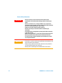
CAUTION
A CAUTION notice denotes a hazard. It calls attention to an operating procedure, practice, or the like
that, if not correctly performed or
adhered to, could result in damage
to the product or loss of important
data. Do not proceed beyond a
CAUTION notice until the indicated
conditions are fully understood and
met.
WA R N I N G
A WARNING notice denotes a
hazard. It calls attention to an
operating procedure, practice, or
the like that, if not correctly performed or adhered to, could result
in personal injury or death. Do not
proceed beyond a WARNING
notice until the indicated conditions are fully understood and
met.
U3606A User’s and Service Guide
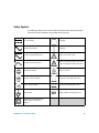
Safety Symbols
The following symbols on the instrument and in the documentation indicate precautions
which must be taken to maintain safe operation of the instrument.
Direct current (DC)
Off (supply)
Alternating current (AC)
On (supply)
Both direct and alternating current
Caution, risk of electric shock
Three-phase alternating current
Caution, risk of danger (refer to this manual
for specific Warning or Caution information)
Earth (ground) terminal
Caution, hot surface
Protective conductor terminal
Out position of a bi-stable push control
Frame or chassis terminal
In position of a bi-stable push control
Equipotentiality
CAT II
300 V
Category II 300 V overvoltage protection
Equipment protected throughout by
double insulation or reinforced
insulation
U3606A User’s and Service Guide
III
General Safety Information
IV
WA R N I N G
• Do not exceed any of the measurement limits defined in the
specifications to avoid instrument damage and the risk of electric
shock.
• Do not use the device if it is damaged. Before you use the device,
inspect the casing. Look for cracks or missing plastic. Do not operate
the device around explosive gas, vapor, or dust.
• Always use the device with the cables provided.
• Observe all markings on the device before establishing any
connection.
• Turn off the device and application system power before connecting
to the I/O terminals.
• When servicing the device, use only the specified replacement parts.
• Do not operate the device with the cover removed or loosened.
• Use only the power adapter provided by the manufacturer to avoid
any unexpected hazards.
CAUTION
• If the device is used in a manner not specified by the manufacturer, the
device protection may be impaired.
• Always use dry cloth to clean the device. Do not use ethyl alcohol or
any other volatile liquid to clean the device.
• Do not permit any blockage of the ventilation holes of the device.
U3606A User’s and Service Guide
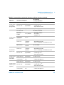
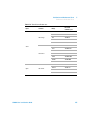
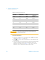
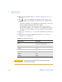
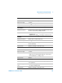
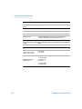
Environmental Conditions
This instrument is designed for indoor use and in an area with low condensation. The table
below shows the general environmental requirements for this instrument.
Environmental conditions
Requirements
Operating temperature
0 °C to 55 °C
Storage temperature
–40 °C to 70 °C
Relative humidity
Up to 80% at 30 °C RH (non-condensing)
NOTE
U3606A User’s and Service Guide
The U3606A Multimeter|DC Power Supply complies with the following safety and
EMC requirements:
• IEC 61010-1:2001/EN61010-1:2001 (2nd Edition)
• Canada: CAN/CSA-C22.2 No. 61010-1-04
• USA: ANSI/UL 61010-1:2004
• IEC 61326-1:2005/EN61326-1:2006
• CISPR11:2003/EN55011:2007, Group 1 Class A
• Canada: ICES/NMB-001:2004
• Australia/New Zealand: AS/NZS CISPR 11:2004
V
Regulatory Markings
The CE mark is a registered trademark
of the European Community. This CE
mark shows that the product complies
with all the relevant European Legal
Directives.
The C-tick mark is a registered
trademark of the Spectrum
Management Agency of Australia. This
signifies compliance with
the Australia EMC Framework
regulations under the terms of the
Radio Communication Act of 1992.
ICES/NMB-001 indicates that this ISM
device complies with the Canadian
ICES-001.
Cet appareil ISM est confomre a la
norme NMB-001 du Canada.
This instrument complies with the
WEEE Directive (2002/96/EC) marking
requirement. This affixed product label
indicates that you must not discard
this electrical or electronic product in
domestic household waste.
The CSA mark is a registered
trademark of the Canadian Standards
Association.
VI
U3606A User’s and Service Guide
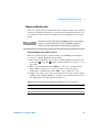
Waste Electrical and Electronic Equipment (WEEE) Directive 2002/96/EC
This instrument complies with the WEEE Directive (2002/96/EC) marking requirement.
This affixed product label indicates that you must not discard this electrical or electronic
product in domestic household waste.
Product Category:
With reference to the equipment types in the WEEE directive Annex 1, this instrument is
classified as a “Monitoring and Control Instrument” product.
The affixed product label is as shown below.
Do not dispose in domestic household waste
To return this unwanted instrument, contact your nearest Agilent Technologies, or visit:
www.agilent.com/environment/product
for more information.
U3606A User’s and Service Guide
VII
In This Guide…
1
Getting Started
This chapter prepares the U3606A Multimeter|DC Power Supply for use, and contains a
brief description of the instrument front panel, display, keypad, terminals, and rear panel.
2
Digital Multimeter Operation
This chapter contains detailed information on how to take measurements using the
U3606A Multimeter|DC Power Supply. It also describes the various multimeter functions
and features available in the U3606A.
3
DC Power Supply Operation
This chapter contains examples on how to operate the DC power supply from the front
panel. The simple examples discussed in this chapter shows you how to program the
output voltage and current functions, the protection functions, and the additional source
functions.
4
System Related Operation
This chapter lists the various items and settings in the utility menu. This chapter also
describes how to store and recall an instrument state with the U3606A Multimeter|DC
Power Supply.
5
Verification and Performance Tests
This chapter contains the procedures for verification of the instrument performance. The
input connections and test setup for each verification procedure is also described in this
chapter.
6
Calibration Procedures
This chapter contains the procedures for the instrument adjustment (calibration). You must
first unsecure the instrument before any adjustment can be done. The steps to secure and
unsecure the instrument for calibration are also described in this chapter.
7
Disassembly and Repair
This chapter will help you troubleshoot a failing instrument. It also describes how to obtain
repair service and lists the replaceable assemblies.
VIII
U3606A User’s and Service Guide
8
Characteristics and Specifications
This chapter specifies the characteristics, environmental conditions, and specifications of
the U3606A.
9
List of Error Messages
The U3606A error messages are summarized in this chapter.
U3606A User’s and Service Guide
IX
Declaration of Conformity (DoC)
The Declaration of Conformity (DoC) for this instrument is available on the Web site. You
can search the DoC by its product model or description.
http://regulations.corporate.agilent.com/DoC/search.htm
NOTE
X
If you are unable to search for the respective DoC, please contact your
local Agilent representative.
U3606A User’s and Service Guide
Table of Contents
Table of Contents
1
Getting Started
Introduction 2
Measurement features
Output features 3
System features 3
2
Initial Inspection 4
Standard purchase items
4
Connecting Power to the Instrument
Adjusting the Handle
6
To Rack Mount the Instrument
Stacking the Instrument
5
7
8
Product at a Glance 9
Product dimensions 9
The front panel at a glance 10
The display at a glance 11
The keypad at a glance 14
The terminals at a glance 19
The rear panel at a glance 22
2
Digital Multimeter Operation
Making Measurements 24
Performing voltage measurements 25
Performing current measurements 29
Performing resistance (2-wire) measurements 33
Performing low-resistance (4-wire) measurements 35
Performing frequency, pulse width, and duty cycle measurements
Performing capacitance measurements 46
Performing continuity tests 49
U3606A User’s and Service Guide
38
XI
Table of Contents
Performing diode tests
Selecting a Range
51
54
Setting the Resolution
55
Math Operations 56
Null 57
dBm measurements 59
dB measurements 60
MinMax 62
Limit 64
Hold 67
Triggering the Multimeter 69
Front panel triggering 70
Remote interface triggering
3
71
DC Power Supply Operation
Basic Operation 74
Constant voltage (CV) mode
Constant current (CC) mode
Protection Functions 78
Overvoltage protection (OVP)
Overcurrent protection (OCP)
Overvoltage limit (OV) 84
Overcurrent limit (OC) 86
Square-wave Output
74
76
78
81
88
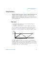
Sweep Functions 93
Ramp signal 93
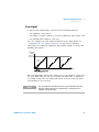
Scan signal 95
Selecting a Range
Enabling the Output
XII
97
98
U3606A User’s and Service Guide
Table of Contents
Remote Sensing
4
99
System Related Operation
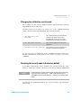
Using the Utility Menu 108
Changing configurable settings
109
Utility Menu Summary 111
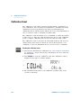
Reading error messages 114
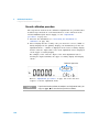
Reading the program code revision 115
Adjusting the display brightness 116
Changing the power-on state 116
Configuring the beeper 117
Connecting to a remote interface 118
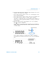
Performing a self-test 120
Selecting a dBm reference resistance value 121
Setting the output protection state 122
Configuring the ramp signal parameters 123
Configuring the scan signal parameters 125
Setting the smooth function 127
Enable refresh hold 130
Enable data hold 131
Storing and Recalling Instrument States
Storing a state 132
Recalling a stored state 133
132
Remote Operation 134
Configuring and connecting the GPIB interface
Configuring and connecting the USB interface
SCPI commands 137
5
135
136
Verification and Performance Tests
Recommended Test Equipment 140
General measurement techniques
U3606A User’s and Service Guide
143
XIII
Table of Contents
Using an electronic load 143
Connecting the current monitoring resistor
Test Considerations
143
144
Input Connections 145
Zero offset verification test setup 145
Gain verification test setup 146
Output verification test setup 147
Verification and Performance Tests Overview
Self-test
152
153
Performance Verification Tests 154
Zero offset verification test 154
Gain verification test 156
Output verification test 161
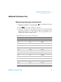
Additional Verification Tests 171
Optional capacitance gain verification test 171
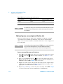
Optional square-wave output verification test 172
6
Calibration Procedures
Calibration Overview 176
Closed-case electronic calibration 176
Agilent Technologies calibration services
Calibration interval 177
Adjustment is recommended 177
Time required for calibration 177
Recommended Test Equipment
Calibration Process
176
178
179
Calibration Security 180
Unsecuring the instrument for calibration 180
Changing the calibration security code 183
XIV
U3606A User’s and Service Guide
Table of Contents
Resetting the security code to the factory default
Calibration Count
183
186
Calibration Message
187
Using the Front Panel for Adjustments 188
Selecting the adjustment mode 188
Entering adjustment values 188
Aborting a calibration in progress 189
General calibration procedure 190
Adjustments procedures 193
Zero offset adjustment 193
Gain adjustments 195
Output adjustments 208
Finishing the adjustments 217
7
Disassembly and Repair
Operating Checklist
220
Cleaning 221
Fuse Replacement
221
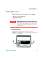
Electrostatic Discharge (ESD) Precautions
226
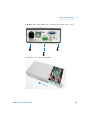
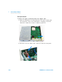
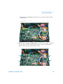
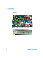
Mechanical Disassembly 227
General disassembly 227
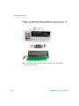
Replaceable Parts 235
To Order Replaceable Parts
8
236
Types of Services Available
237
Repackaging for Shipment
238
Characteristics and Specifications
Product Characteristics
U3606A User’s and Service Guide
240
XV
Table of Contents
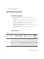
Digital Multimeter Specifications 242
Specification assumptions 242
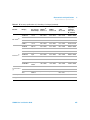
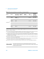
DC specifications 242
AC specifications 245
Frequency specifications 246
Duty cycle and pulse width specifications
Operating specifications 248
Supplementary characteristics 249
247
DC Power Supply Specifications 253
Safety considerations 253
Specifications assumptions 253
Performance specifications 254
Supplementary characteristics 255
9
List of Error Messages
Error Messages 260
Command errors 261
Execution errors 262
Internal errors 263
Query errors 263
Device specific errors 263
Self-test errors 264
Calibration errors 265
XVI
U3606A User’s and Service Guide
List of Figures
List of Figures
Figure 1-1
Figure 1-2
Figure 1-3
Figure 1-4
Figure 1-5
Figure 1-6
Figure 1-7
Figure 1-8
Figure 2-1
Figure 2-2
Figure 2-3
Figure 2-4
Figure 2-5
Figure 2-6
Figure 2-7
Figure 2-8
Figure 2-9
Figure 3-1
Figure 3-2
Figure 3-3
Figure 3-4
Figure 5-1
Figure 5-2
Figure 5-3
Figure 5-4
Figure 5-5
Figure 5-6
Figure 5-7
Figure 5-8
Figure 5-9
U3606A User’s and Service Guide
U3606A handle adjustments 6
U3606A stacking directions 8
U3606A dimensions 9
U3606A front panel 10
VFD full display with all segments illuminated 11
U3606A keypad with both multimeter and source operations 14
U3606A connector terminals 19
U3606A rear panel 22
Terminal connections for voltage measurements 25
Terminal connections for current measurements 29
Terminal connections for 2-wire resistance measurements 33
Terminal connections for 4-wire resistance measurements 36
Terminal connections for frequency, pulse width, and duty cycle
measurements via the voltage path 38
Terminal connections for frequency, pulse width, and duty cycle
measurement via the current path 39
Terminal connections for capacitance measurements 47
Terminal connections for continuity tests 49
Terminal connections for diode tests 51
Constant voltage mode terminal connections 74
Constant current mode terminal connections 76
Remote sensing connections 100
Local sensing connections 100
Test setup for zero offset (short) verification 145
Test setup for DC voltage, AC voltage, resistance, and capacitance gain
verification 146
Test setup for DC current and AC current gain verification 146
Test setup for frequency gain verification 147
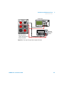
Test setup for CV programming and readback accuracy
verification 147
Test setup for CV load and line regulation verification 148
Test setup for CV noise effect verification 148
Test setup for load transient response time verification 149
Test setup for CC programming and readback accuracy
verification 149
XVII
List of Figures
Figure 5-10
Figure 5-11
Figure 5-12
Figure 5-13
Figure 6-1
XVIII
Test setup for CC line and load regulation verification 150
Test setup for CC noise effect verification 150
Test setup for square-wave output verification 151
Load transient response time 166
SECUR pads location 184
U3606A User’s and Service Guide
List of Tables
List of Tables
Table 1-1
Table 1-2
Table 1-3
Table 1-4
Table 2-1
Table 2-2
Table 2-3
Table 2-4
Table 2-5
Table 2-6
Table 2-7
Table 2-8
Table 2-9
Table 2-10
Table 2-11
Table 2-12
Table 3-1
Table 4-1
Table 4-2
Table 4-3
Table 4-4
Table 5-1
U3606A display annunciators 11
U3606A keypad functions 15
Input terminal connections for measurement functions 20
Output terminal connections for source functions 21
DC voltage measurement summary 26
AC voltage measurement summary 27
DC current measurement summary 30
AC current measurement summary 31
Resistance measurement summary 34
Low-resistance measurement summary 37
Frequency measurement (voltage path) summary 40
Frequency measurement (current path) summary 43
Capacitance measurement summary 48
Continuity function summary 50
Diode function summary 52
Math operations summary 56
Available frequencies for square-wave output 90
Utility menu key descriptions 108
Utility menu item descriptions 111
Ramp signal parameters 123
Scan signal parameters 125
Recommended test equipment for performance verification
procedures 140
Table 5-2 Zero offset verification test 155
Table 5-3 DC voltage gain verification test 156
Table 5-4 DC current gain verification test 157
Table 5-5 AC voltage gain verification test 158
Table 5-6 AC current gain verification test 159
Table 5-7 Resistance gain verification test 159
Table 5-8 Frequency gain verification test 160
Table 5-9 Constant voltage programming and readback accuracy verification
test 161
Table 5-10 Constant voltage load effect verification test 162
Table 5-11 Constant voltage source effect verification test 163
Table 5-12 Constant current programming and readback accuracy verification
U3606A User’s and Service Guide
XIX
List of Tables
Table 5-13
Table 5-14
Table 5-15
Table 5-16
Table 5-17
Table 5-18
Table 6-1
Table 6-2
Table 6-3
Table 6-4
Table 6-5
Table 6-6
Table 6-7
Table 6-8
Table 6-9
Table 6-10
Table 6-11
Table 6-12
Table 7-1
Table 8-1
Table 8-2
Table 8-3
Table 8-4
Table 8-5
Table 8-6
Table 8-7
Table 8-8
Table 8-9
Table 8-10
Table 8-11
Table 9-1
Table 9-2
Table 9-3
Table 9-4
Table 9-5
Table 9-6
Table 9-7
XX
test 167
Constant current load effect verification test 168
Constant current source effect verification test 169
Optional capacitance gain verification test 171
Square-wave amplitude output verification test 173
Square-wave frequency output verification test 173
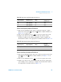
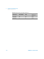
Square-wave duty cycle output verification test 174
Recommended test equipment for adjustment procedures 178
Valid gain adjustment input values 196
DC voltage gain adjustment 198
AC voltage gain adjustment 200
Frequency gain adjustment 201
Resistance gain adjustment 202
DC current gain adjustment 204
AC current gain adjustment 205
Capacitance gain adjustment 206
Valid output adjustment levels 208
Constant current output adjustment 210
Constant voltage output adjustment 213
List of replaceable parts 235
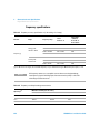
DC accuracy specifications ± (% of reading + % of range) 242
AC accuracy specifications ± (% of reading + % of range) 245
Frequency accuracy specifications ± (% of reading + % of range) 246
Frequency sensitivity for voltage measurement 246
Frequency sensitivity for current measurement 247
Duty cycle and pulse width resolution and accuracy 247
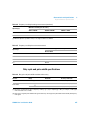
Reading speed (typical) 248
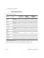
DC power supply performance specifications 254
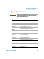
Square-wave output specifications 256
Scan output specifications 258
Ramp output specifications 258
List of command errors 261
List of execution errors 262
List of internal errors 263
List of query errors 263
List of device specific errors 263
List of self-test errors 264
List of calibration errors 265
U3606A User’s and Service Guide
U3606A Multimeter|DC Power Supply
User’s and Service Guide
1
Getting Started
Introduction 2
Measurement features 2
Output features 3
System features 3
Initial Inspection 4
Standard purchase items 4
Connecting Power to the Instrument 5
Adjusting the Handle 6
To Rack Mount the Instrument 7
Product at a Glance 9
Product dimensions 9
The front panel at a glance 10
The display at a glance 11
The keypad at a glance 14
The terminals at a glance 19
The rear panel at a glance 22
This chapter prepares the U3606A Multimeter|DC Power Supply for use,
and contains a brief description of the instrument front panel, display,
keypad, terminals, and rear panel.
Agilent Technologies
1
1
Getting Started
Introduction
Introduction
The Agilent U3606A Multimeter|DC Power Supply unit is a combination of
a 5½ digit digital multimeter and a 30 W single output dual- range
DC power supply with a square- wave generator. These two distinctive
modules are able to work simultaneously (excand independently, providing
an efficient, convenient, and affordable testing solution.
The U3606A has the dimensions of 2½U (rack unit) high, and provides the
flexibility for bench or rack- mounted use.
The front panel controls allow you to set the measurement parameters,
mathematical operations, output parameters, protection features, and
instrument settings.
The rear panel includes a GPIB and USB interface connector, as well as
output terminals capable of remote sensing.
When operating over the remote interface, the U3606A functions as both a
listener and a talker. Using an external controller (such as a PC), you can
instruct the U3606A to make a measurement, output a source, or send
data back over the GPIB or USB interfaces.
Measurement features
• 5½ digit, 120000 count
• Voltage and current measurement — DC, AC (true- rms), and AC+DC
• 2- wire resistance measurement up to 100 MΩ
• 4- wire low- resistance measurement (100 mΩ to 10 Ω)
• Continuity and diode test
• Frequency, pulse width, and duty cycle measurement — via the voltage
path or via the current path
• Capacitance measurement
• Auto and manual ranging
• Mathematical operations for null, decibel (dBm and dB) measurements,
statistics (MinMax), limit, and hold
• Triggering for local and remote operation
2
U3606A User’s and Service Guide
Getting Started
Introduction
1
Output features
• Single- output dual range — S1 (30 V/1 A) or S2 (8 V/3 A)
• Constant voltage and constant current supply
• Overvoltage and overcurrent protection
• Remote sensing to compensate for voltage drop in load leads
• Square- wave generator with selectable amplitude, frequency, duty cycle,
and pulse width parameters
• Output on standby when disabled
• Ramp signal capability with fixed time for preset step and end
amplitude
• Scan signal capability with preset time, step, and end amplitude
• Excellent load and line regulation
• Low ripple and noise
System features
• Highly visible vacuum- fluorescent display (VFD)
• Built- in GPIB (IEEE- 488) and USB interface, I/O setup easily done from
the front- panel
• USB 2.0 full speed interface — USBTMC488.2 compatible
• Compatible with Standard Commands for Programmable Instruments
(SCPI)
• Automatic power- on self- test
• Error messages available from the front- panel display
• User calibration from front panel and remote interface — software
calibration, no internal physical adjustments
• Sixteen storage locations for user- defined operating states
• Portable, rugged case with non- skid feet
• Kensington security slot — anti- theft system
U3606A User’s and Service Guide
3
1
Getting Started
Initial Inspection
Initial Inspection
When you receive your instrument, inspect the unit for any obvious
damage such as broken terminals or cracks, dents, and scratches on the
casing that may occur during shipment.
If any damage is found, notify the nearest Agilent Sales Office
immediately. The front of this manual contains the warranty information.
Standard purchase items
Verify that you have received the following items with your unit. If
anything is missing or damaged, please contact the nearest Agilent Sales
Office.
✔ Power cord
✔ U8201A Combo test lead kit (test leads, alligator clips, SMT grabbers,
fine tip test probes, mini- grabbers)
✔ USB Standard- A to Type- B interface cable
✔ Printed Agilent U3606A Multimeter|DC Power Supply Quick Start Guide
✔ Agilent Automation- Ready CD- ROM (contains the Agilent IO Libraries
Suite)
✔ Agilent U3606A Product Reference CD- ROM
✔ Certificate of Calibration
Keep the original packaging in case the U3606A has to be returned to
Agilent in the future. If you return the U3606A for service, attach a tag
identifying the owner and model number. Also, include a brief description
of the problem.
4
U3606A User’s and Service Guide
Getting Started
Connecting Power to the Instrument
1
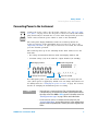
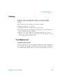
Connecting Power to the Instrument
Connect the power cord to the AC power connector (see “The rear panel
at a glance” on page 22 for the AC power connector location). The mains
plug should only be inserted into a socket outlet that provides protective
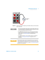
earth contact. Push the power switch to turn on the instrument.
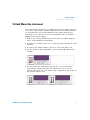
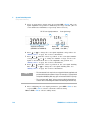
The front- panel display illuminates while the U3606A performs its
power- on self- test. (If the instrument does not power- on, refer to the
“Operating Checklist” on page 220). If self- test is successful, the U3606A
goes into normal operation.
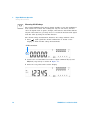
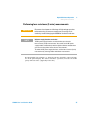
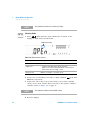
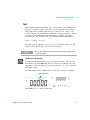
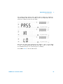
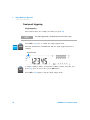
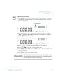
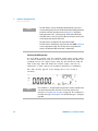
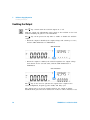
The U3606A powers up in the following modes when turned on for the
first time:
• DC voltage measurement function with autoranging enabled, and
• Constant voltage (CV) mode with the output disabled (on standby).
Autoranging enabled
DC voltage measurement
Constant voltage mode
Output on standby
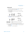
For subsequent power cycles, the U3606A returns to the last power- off
state (when power is applied) by default. You can change this behavior in
the utility menu. See “Changing the power- on state” on page 116 for more
details on changing the instrument power- on setting.
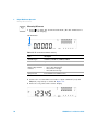
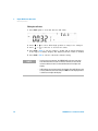
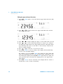
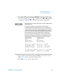
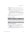
NOTE
• If the self-test is unsuccessful, the Error is displayed on the right
side of the display. To read the error number, you will need to access
the utility menu. Press Shift > Utility to access the utility menu. See
“Reading error messages” on page 114 for more information.
• A more extensive self-test is available from the utility menu. See
“Using the Utility Menu” on page 108 for details. In the unlikely event
that the self-test repeatedly fails, contact your nearest Agilent Sales
Office.
U3606A User’s and Service Guide
5
1
Getting Started
Adjusting the Handle
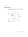
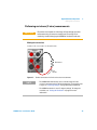
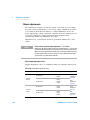
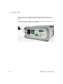
Adjusting the Handle
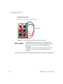
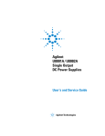
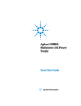
To adjust the handle, grasp the handle by the sides and pull outward.
Then, rotate the handle to the desired position. The various positions
available are illustrated below.
Bench-top
viewing positions
Carrying
position
Figure 1-1 U3606A handle adjustments
6
U3606A User’s and Service Guide
Getting Started
To Rack Mount the Instrument
1
To Rack Mount the Instrument
You can mount the U3606A in a standard 19- inch rack cabinet using one
of the three optional kits available. Instructions and mounting hardware
are included with each rack- mounting kit. Any Agilent Technologies
instrument of the same size can be rack- mounted beside the U3606A
Multimeter|DC Power Supply.
1 Remove the carrying handle and the front and rear rubber bumpers
before rack- mounting the instrument.
2 To remove the handle, rotate it to a vertical position and pull the ends
outward.
3 To remove the rubber bumpers, stretch a corner and slide it off.
4 To rack mount a single instrument, order U3606A- ICM (adapter kit
34190A).
5 To rack mount two instruments side- by- side, order U3606A- ICN
(lock- link kit 34194A and flange kit 34191A). Be sure to use the
support rails inside the rack cabinet. This configuration only works for
two U3606A side- by- side.
U3606A User’s and Service Guide
7
1
Getting Started
Stacking the Instrument
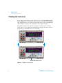
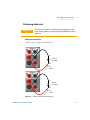
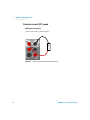
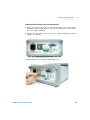
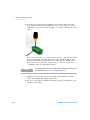
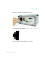
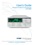
Stacking the Instrument
If you have purchased more than one unit of the U3606A Multimeter|DC
Power Supply, you can stack the units on top of each other. The warning
sign Stackable Direction located at the bottom side of the front and back
rubber bumpers indicate the orientation of the rubber bumpers.
The rubber bumpers are uniquely designed to firmly secure the units
stacked above it, preventing any unwanted movements. You may stack as
many units as you want on top of each other.
Stackable Direction indicator
Figure 1-2 U3606A stacking directions
8
U3606A User’s and Service Guide
Getting Started
Product at a Glance
1
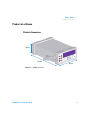
Product at a Glance
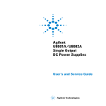
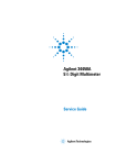
Product dimensions
105 mm
329 mm
255 mm
Figure 1-3 U3606A dimensions
U3606A User’s and Service Guide
9
1
Getting Started
Product at a Glance
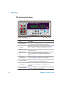
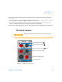
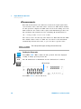
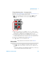
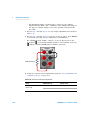
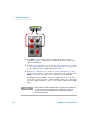
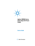
The front panel at a glance
1
2
3
5
7
8
4
6
Figure 1-4 U3606A front panel
Item
10
Description
1
Source terminals
Positive (FORCE +) and negative (FORCE –) connector terminals for
source operation and 4-wire low-resistance measurement.
2
VFD display
Displays the instrument settings and readings. See “The display at a
glance” on page 11 for a complete list of all display annunciators.
3
Multimeter terminals
Positive (SENSE +) and negative (SENSE –) connector terminals for
multimeter operation.
4
Multimeter function
keys
Function keys for multimeter operation. See “Multimeter
operation” on page 16 for a complete list of all multimeter key
functions.
5
Autorange and
manual range keys
Select a manual range for multimeter operation or enable autoranging.
See “Selecting a Range” on page 54 for more information.
6
Source function keys
Function keys for source operation. See “Source operation” on
page 17 for a complete list of all source key functions.
7
Local/Shift key
Perform shifted functions and enables front panel operation during
remote lock. See “Using the Shift key” on page 14 for more
information.
8
Power On/Off button
Turns the power supply on or off. See “Connecting Power to the
Instrument” on page 5 for more information.
U3606A User’s and Service Guide
Getting Started
Product at a Glance
1
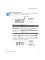
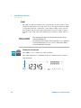
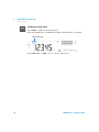
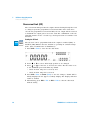
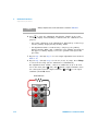
The display at a glance
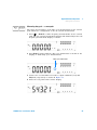
Figure 1-5 VFD full display with all segments illuminated
To view the full display (with all segments illuminated), press and hold
Hold while powering- on the U3606A. After you are done viewing the full
display, press Hold again to resume normal operation.
Table 1-1 U3606A display annunciators
Annunciator
Description
A single reading is taken from the input (+ SENSE –) terminals
Trig
Single trigger mode is active
Hold
Hold math operation enabled
MinMaxAvg
MinMax math operation enabled
Avg
When Avg is flashing, the smooth function is enabled
Null
Null math operation enabled
Diode test function selected
Continuity test function selected
Resistance (2-wire) measurement selected
Shift
Shift mode selected
Limit
Limit math operation enabled
Auto
Autoranging selected
DC measurement selected
U3606A User’s and Service Guide
11
1
Getting Started
Product at a Glance
Table 1-1 U3606A display annunciators (continued)
Annunciator
Description
AC measurement selected
AC+DC measurement selected
ºC
Celsius temperature unit (feature not applicable with the U3606A)
ºF
Fahrenheit temperature unit (feature not applicable with the U3606A)
dB
Decibel unit relative to 1 dBm
dBm
Decibel unit relative to 1 mW
ms
Pulse width unit
%
Duty cycle unit
MkΩ
Resistance units: Ω, kΩ, MΩ
MkHz
Frequency units: Hz, kHz, MHz
mV
Voltage units: mV, V
mA
Current units: mA, A
μnF
Capacitance units: nF, μF
EXT
Remote sensing mode enabled
CC
Constant current mode selected
CV
Constant voltage mode selected
Lo Ω
Low-resistance (4-wire) measurement selected
Square-wave output selected
12
S1
Output range S1 selected — 30 V/1 A
S2
Output range S2 selected — 8 V/3 A
V
Voltage unit: V for constant voltage mode
A
Current unit: A for constant current mode
Hz
Frequency unit: Hz for square-wave output
LOG
Data logging in progress (feature not applicable with the U3606A)
U3606A User’s and Service Guide
Getting Started
Product at a Glance
1
Table 1-1 U3606A display annunciators (continued)
Annunciator
Description
Store
Store instrument state selected
Recall
Recall instrument state selected
Ramp
Ramp signal output selected
Scan
Scan signal output selected
Error
One or more errors available in the error queue
Rmt
Remote interface control is active
OV
Overvoltage condition active
OC
Overcurrent condition active
OUT
Output is enabled from the output (+ FORCE –) terminals and remote sense
(rear output) terminals
SBY
Output is on standby (disabled)
ms
Pulse width unit for square-wave output
%
Duty cycle unit for square-wave output
V
Voltage unit: V for overvoltage protection
A
Current unit: A for overcurrent protection
U3606A User’s and Service Guide
13
1
Getting Started
Product at a Glance
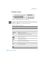
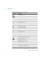
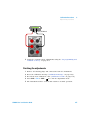
The keypad at a glance
Figure 1-6 U3606A keypad with both multimeter and source operations
The operation of each key is shown below. Pressing a key changes the
current operation, illuminates a related annunciator on the display, and
generates a key- click sound (a beep).
Using the Shift key
The front panel has two rows of keys to select various functions and
operations. Most keys have a shifted function printed in blue above the
key. To perform a shifted function: first, press Shift (the Shift annunciator
will illuminate). Then, press the key that has the desired label above it.
The dBm, Store, Lo Ω, Limit, Auto, Protect, Limit, 4½ 5½, Recall, Trig, Utility, Save,
Exit, EXT, and Range functions/operations can only be accessed using the
Shift key.
Shift annunciator
As an example, to enable the limit math operation, first press Shift. While
the Shift annunciator is illuminated, press MinMax (Limit).
If you accidentally press Shift, but do not want to perform a shifted
function, just press it again to turn off the Shift annunciator. If no
key- press is detected 3 seconds after Shift is pressed, the instrument will
return to normal operation (the Shift annunciator will turn off).
14
U3606A User’s and Service Guide
Getting Started
Product at a Glance
1
Table 1-2 U3606A keypad functions
Key
Description
System related operation
Push Power to turn on or turn off the U3606A Multimeter|DC Power Supply.
• Press Shift to perform a shifted function. See “Using the Shift key” on page 14 for more
information.
• Press Shift to unlock the front-panel keys when in remote operation lock. See “Remote
Operation” on page 134 for more information.
Press Shift > Utility to access the utility menu. See “Using the Utility Menu” on page 108
for more information.
• Press
or
to step through items in the utility menu.
• Press
or
to move the cursor to the left or to the right.
• See “Using the Utility Menu” on page 108 and “Changing configurable settings” on
page 109 for more information.
• Press
or
to enter the edit mode in the utility menu for configurable settings.
• Press
or
to switch between two values, to select a value from the list, or to
decrease or increase a value.
• See “Using the Utility Menu” on page 108 and “Changing configurable settings” on
page 109 for more information.
Press Shift > Save to save the changes made in the edit mode. See “Changing configurable
settings” on page 109 for more information.
• Press Shift > Exit to exit the edit mode or utility menu without saving. See “Changing
configurable settings” on page 109 for more information.
• Press Shift > Exit to toggle off a math operation (Null, dBm, dB, MinMax, Limit, Hold).
See “Math Operations” on page 56 for more information.
Press Shift > Store to store an instrument state. See “Storing a state” on page 132 for
more information.
U3606A User’s and Service Guide
15
1
Getting Started
Product at a Glance
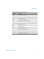
Table 1-2 U3606A keypad functions (continued)
Key
Description
Press Shift > Recall to recall a previously stored instrument state. See “Recalling a stored
state” on page 133 for more information.
Multimeter operation
Press
V to cycle between the DC, AC, and AC+DC voltage measurement functions. See
“Performing voltage measurements” on page 25 for more information.
Press
I to cycle between the DC, AC, and AC+DC current measurement functions. See
“Performing current measurements” on page 29 for more information.
• Press
to select the resistance (2-wire) measurement function. See “Performing
resistance (2-wire) measurements” on page 33 for more information.
• Press
again to select the continuity test function. See “Performing continuity
tests” on page 49 for more information.
Press Shift > Lo Ω to select the low-resistance (4-wire) measurement function. See
“Performing low-resistance (4-wire) measurements” on page 35 for more information.
Press Hz ms % to cycle between the frequency (Hz), pulse width (ms), and duty cycle (%)
measurement functions related to the voltage or current path.[1] See “Performing
frequency, pulse width, and duty cycle measurements” on page 38 for more information.
• Press
to select the diode test function. See “Performing diode tests” on
page 51 for more information.
• Press
again to select the capacitance function. See “Performing capacitance
measurements” on page 46 for more information.
Press Null to enable the null math operation. See “Null” on page 57 for more information.
Press Shift > dBm to convert the measured voltage value to dBm. See “dBm
measurements” on page 59 for more information.
Press Shift > dBm > dB to convert the measured voltage value to dB. See “dB
measurements” on page 60 for more information.
16
U3606A User’s and Service Guide
Getting Started
Product at a Glance
1
Table 1-2 U3606A keypad functions (continued)
Key
Description
Press MinMax to store statistical data for the current readings. See “MinMax” on page 62
for more information.
Press Shift > Limit to enable the limit math operation. See “Limit” on page 64 for more
information.
Press Hold to capture and hold a reading within the specified variation and threshold
values.[2] See “Hold” on page 67 for more information.
• Press
to select a higher range and disable autoranging.
• Press
to select a lower range and disable autoranging.
• See “Selecting a Range” on page 54 for more information.
Press Shift > Auto to enable autoranging and disable manual ranging. See “Selecting a
Range” on page 54 for more information.
Press Shift > 4½ 5½ to toggle between 4½ digit and 5½ digit mode. See “Setting the
Resolution” on page 55 for more information.[3]
Press Shift > Trig to enable the single trigger mode. See “Triggering the Multimeter” on
page 69 for more information.
Source operation
Press Voltage to select CV output. Use the directional keys to select a suitable voltage
value. See “Constant voltage (CV) mode” on page 74 for more information.
Press Current to select CC output. Use the directional keys to select a suitable current
value. See “Constant current (CC) mode” on page 76 for more information.
U3606A User’s and Service Guide
17
1
Getting Started
Product at a Glance
Table 1-2 U3606A keypad functions (continued)
Key
Description
• Press
to select the square-wave output. Use the directional keys to set the
voltage amplitude.
• Press
again to cycle through the duty cycle, pulse width, and voltage amplitude
settings.
• See “Square-wave Output” on page 88 for more information.
When the
frequencies.
annunciator is flashing, press
or
to step through the available
While the
annunciator is flashing, press
or
to set the voltage amplitude, or
to step through the available duty cycle values or pulse width values.
Press Sweep to cycle through the ramp and scan sweep functions, or to disable the sweep
mode for the selected output (CV or CC).[4] See “Sweep Functions” on page 93 for more
information.
Press Shift > Limit to set the overcurrent limit value for the CV output or the overvoltage
limit value for the CC output. See “Protection Functions” on page 78 for more information.
Press Shift > Protect to set the overcurrent protection value for the CV output or the
overvoltage protection value for the CC output[5]. See “Protection Functions” on page 78
for more information.
Press Shift > Range to toggle between range S1 (30 V/1 A) and range S2 (8 V/3 A)[6]. See
“Selecting a Range” on page 97 for more information.
UT
Press OS BY
to toggle between source output (OUT) and source standby (SBY). See
“Enabling the Output” on page 98 for more information.
Press Shift > EXT to enable remote sensing. See “Remote Sensing” on page 99 for more
information.
[1] The voltage path is the default path when you select the frequency measurement function. To switch to the current path for
I , then press Hz ms %.
frequency, pulse width, and duty cycle measurements, first press
[2] The refresh hold variation and threshold values can be configured through the utility menu. See Chapter 4, “System Related
Operation,” starting on page 107 for more information on the utility menu.
18
U3606A User’s and Service Guide
Getting Started
Product at a Glance
1
[3] The continuity and diode test functions have a fixed 4½ digit resolution. Capacitance measurement is fixed to 3½ digit
resolution.
[4] The sweep functions can only be accessed when the U3606A is in constant voltage or constant current mode. You cannot
access the sweep functions while the U3606A is in square-wave output mode.
[5] The overcurrent and overvoltage protection features are only active when the output protection state is enabled. See
Chapter 4, “Setting the output protection state,” starting on page 122 for more information.
[6] You can only change the range when the instrument output is in the “standby” state (the SBY annunciator is illuminated).
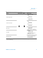
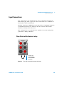
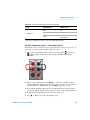
The terminals at a glance
CAUTION
To avoid damaging this device, do not exceed the rated input limit.
Positive output terminals (
Negative output terminals (
)
)
Positive input terminals (V,
, ,
Negative input terminals (LO)
)
Positive input terminals (I)
Current input fuse
Figure 1-7 U3606A connector terminals
U3606A User’s and Service Guide
19
1
Getting Started
Product at a Glance
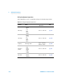
Table 1-3 Input terminal connections for measurement functions
Function
Input terminals (+ SENSE –)
1000 Vrms on all ranges,
< 0.3 A short circuit
DC voltage measurement
AC voltage measurement
Input protection
V
LO
750 Vrms on all ranges
Frequency, duty cycle, and pulse width
measurement via the voltage path
Capacitance measurement
LO
1000 Vrms on all ranges,
< 0.3 A short circuit
Diode test
LO
1000 Vrms on all ranges,
< 0.3 A short circuit
LO
1000 Vrms on all ranges,
< 0.3 A short circuit
LO
1000 Vrms on all ranges,
< 0.3 A short circuit
Resistance (2-wire) measurement
Continuity test
Low-resistance (4-wire) measurement
1000 Vdc on all ranges,
3.15 A/250 V FF fuse
DC current measurement
AC current measurement
I
LO
3.15 A/500 V FF fuse
Frequency, duty cycle, and pulse width
measurements via the current path
20
U3606A User’s and Service Guide
Getting Started
Product at a Glance
1
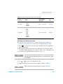
Table 1-4 Output terminal connections for source functions
Function
Output terminals (+ FORCE –)
Maximum output
Constant voltage output
• Amplitude: 0 V to 30 V[1]
• OCP
• S1: 0 A to 1.1 A
• S2: 0 A to 3.3 A
• OC:
• S1: 0 A to 1.05 A
• S2: 0 A to 3.15 A
Constant current output
• Amplitude: 0 A to 3 A[1]
• OVP:
• S1: 0 V to 33 V
• S2: 0 V to 8.8 V
• OV:
• S1: 0 V to 31.5 V
• S2: 0 V to 8.4 V
Ramp output
• Amplitude:
• CV: 0 V to 30 V[1]
• CC: 0 A to 3 A[1]
• Number of steps: 1 to 10000 steps
Scan output
• Amplitude:
• CV: 0 V to 31.5 V[1]
• CC: 0 A to 3.15 A[1]
• Number of steps: 1 to 100 steps
• Dwelling time: 1 to 99 s
Square-wave output
•
•
•
•
Amplitude: 0 V to 30 V[1]
Frequency: 27 predefined values
Duty cycle: 256 steps
Pulse width: 256 steps
[1] Limited by range selected, S1 (30 V/1 A ) or S2 (8 V/3 A). See “Selecting a Range” on page 97 for more information on how
to select a suitable range.
U3606A User’s and Service Guide
21
1
Getting Started
Product at a Glance
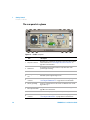
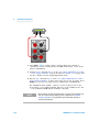
The rear panel at a glance
3
1
4
5
2
9
7
6
8
Figure 1-8 U3606A rear panel
Item
22
Description
1
AC power connector
Plug the power cord firmly into the power receptacle on the rear panel
of the instrument. See “Connecting Power to the Instrument” on
page 5 for more information.
2
AC line fuse
To maintain protection, replace this fuse only with a fuse of the
specified type and rating.
3
Ventilation fan
Ventilation fan to exhaust heat and air from the instrument.
4
Kensington security
slot
Anti-theft system using Kensington locks.
5
GPIB interface
connector
GPIB (IEEE-488) connector physical interface. See “Configuring and
connecting the GPIB interface” on page 135 for more information.
6
Chassis ground lug
Connect to earth ground or to unit chassis to eliminate noise caused
by ground loops.
7
Rear output terminals
Rear panel terminals for remote sense. See “Remote Sensing” on
page 99 for more information.
8
Short bar
Shorts the rear output (+ and –) and sense (+S and –S) terminals .
9
USB interface
connector
Type-B USB connector physical interface. See “Configuring and
connecting the USB interface” on page 136 for more information.
U3606A User’s and Service Guide
U3606A Multimeter|DC Power Supply
User’s and Service Guide
2
Digital Multimeter Operation
Making Measurements 24
Performing voltage measurements 25
Performing current measurements 29
Performing resistance (2-wire) measurements 33
Performing low-resistance (4-wire) measurements 35
Performing frequency, pulse width, and duty cycle measurements 38
Performing capacitance measurements 46
Performing continuity tests 49
Performing diode tests 51
Selecting a Range 54
Setting the Resolution 55
Math Operations 56
Null 57
dBm measurements 59
dB measurements 60
MinMax 62
Limit 64
Hold 67
Triggering the Multimeter 69
Front panel triggering 70
Remote interface triggering 71
This chapter contains detailed information on how to take measurements
using the U3606A Multimeter|DC Power Supply. It also describes the
various multimeter functions and features available in the U3606A.
Agilent Technologies
23
2
Digital Multimeter Operation
Making Measurements
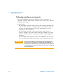
Making Measurements
The following pages introduce the many types of measurements that you
can make with the U3606A, and how to make the connections for each
measurement.
NOTE
• Most basic measurements can be made using the instrument factory
default settings.
• For remote operation, refer to the MEASure, CONFigure, and
CALCulate subsystem in the U3606A Programmer’s Reference.
CAUTION
24
Ensure that terminal connections are correct for that particular
measurement before making any measurement. For each
measurement, connect the test leads as shown. To avoid damaging the
device, do not exceed the rated input limit.
U3606A User’s and Service Guide
Digital Multimeter Operation
Making Measurements
2
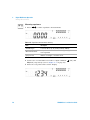
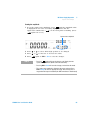
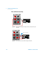
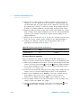
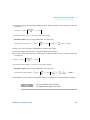
Performing voltage measurements
Making the connections
Connect the test leads as shown below:
–
AC or DC
voltage source
+
Figure 2-1 Terminal connections for voltage measurements
NOTE
• The U3606A will automatically select a suitable range for voltage
measurements by default (autoranging). To manually select a range,
see “Selecting a Range” on page 54 for more information.
• The U3606A resolution is set to 5½ digits by default. To change the
resolution, see “Setting the Resolution” on page 55 for more
information.
U3606A User’s and Service Guide
25
2
Digital Multimeter Operation
Making Measurements
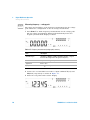
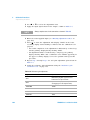
Measuring DC voltage
1 Press
V to make DC voltage measurements. (The DC annunciator is
shown on the display.)
DC annunciator
Table 2-1 DC voltage measurement summary
Item
Description
Available ranges
19.9999 mV, 100.000 mV, 1.00000 V, 10.0000 V, 100.000 V, 1000.00 V
Measurement method
Sigma Delta A-to-D converter
Input impedance
10 MΩ ± 2% range (typical) in parallel with capacitance < 120 pF
Input protection
1000 Vrms on all ranges, < 0.3 A short circuit
2 Connect the red and black test leads to input terminals V (red) and
LO (black) respectively as shown in Figure 2- 1.
3 Probe the test points and read the display.
26
U3606A User’s and Service Guide
Digital Multimeter Operation
Making Measurements
2
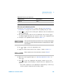
Measuring AC voltage
1 Press
V again (until the AC annunciator is shown on the display) to
make AC voltage measurements.
AC annunciator
Table 2-2 AC voltage measurement summary
Item
Description
Available ranges
100.000 mV, 1.00000 V, 10.0000 V, 100.000 V, 750.00 V
Measurement method
AC coupled true rms
Input impedance
1 MΩ ± 2% range (typical) in parallel with capacitance < 120 pF
Input protection
750 Vrms on all ranges
Crest factor
For < 5:1 errors included. Limited by the peak input and 100 kHz
bandwidth. Maximum 3.0 at full scale.
Peak input
300% of range. Limited by maximum input.
2 Connect the red and black test leads to input terminals V (red) and
LO (black) respectively as shown in Figure 2- 1.
3 Probe the test points and read the display.
U3606A User’s and Service Guide
27
2
Digital Multimeter Operation
Making Measurements
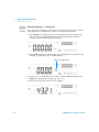
Measuring AC+DC voltage
The U3606A Multimeter|DC Power Supply includes a true- rms multimeter
that returns an accurate rms reading not only for sine waves, but also
other AC signals such as square, triangle, and staircase waveforms without
any DC offset. However, you may choose to return the measured AC signal
with DC offset by using the AC+DC function.
The AC+DC voltage measurement measures AC voltage with DC offset.
1 Press
V again ((until the AC+DC annunciator is shown on the
display) to make AC+DC voltage measurements.
AC+DC annunciator
2 Connect the red and black test leads to input terminals V (red) and
LO (black) respectively as shown in Figure 2- 1.
3 Probe the test points and read the display.
28
U3606A User’s and Service Guide
Digital Multimeter Operation
Making Measurements
2
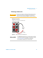
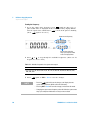
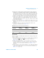
Performing current measurements
Making the connections
Connect the test leads as shown below:
–
AC or DC
current source
+
Figure 2-2 Terminal connections for current measurements
NOTE
• The U3606A will automatically select a suitable range for current
measurements by default (autoranging). To manually select a range,
see “Selecting a Range” on page 54 for more information.
• The U3606A resolution is set to 5½ digits by default. To change the
resolution, see “Setting the Resolution” on page 55 for more
information.
U3606A User’s and Service Guide
29
2
Digital Multimeter Operation
Making Measurements
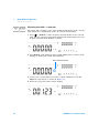
Measuring DC current
1 Press
I to make DC current measurement. (The DC annunciator is
shown on the display.)
DC annunciator
Table 2-3 DC current measurement summary
Item
Description
Available ranges
10.0000 mA, 100.000 mA, 1.00000 A, 3.0000 A
Measurement method
Sigma Delta A-to-D converter
Burden voltage and shunt
resistance
•
•
•
•
Input protection
Protected with a 3.15 A/500 V, FF fuse
< 0.2 V, 10 Ω for 10 mA range
< 0.2 V, 1 Ω for 100 mA range
< 0.3 V, 0.1 Ω for 1 A range
< 0.7 V, 0.01 Ω for 3 A range
2 Connect the red and black test leads to input terminals I (red) and
LO (black) respectively as shown in Figure 2- 2.
3 Probe the test points and read the display.
30
U3606A User’s and Service Guide
Digital Multimeter Operation
Making Measurements
2
Measuring AC (rms) current
1 Press
I again (until the AC annunciator is shown on the display) to
make AC current measurements.
AC annunciator
Table 2-4 AC current measurement summary
Item
Description
Available ranges
10.0000 mA, 100.000 mA, 1.00000 A, 3.0000 A
Measurement method
AC coupled true rms
Burden voltage and shunt
resistance
•
•
•
•
Input protection
Protected with a 3.15 A/500 V, FF fuse
Crest factor
For < 5:1 errors included. Limited by the peak input and 100 kHz
bandwidth. Maximum 3.0 at full scale.
Peak input
300% of range. Limited by maximum input.
< 0.2 V/10 Ω for 10 mA range
< 0.2 V/1 Ω for 100 mA range
< 0.3 V/0.1 Ω for 1 A range
< 0.7 V/0.01 Ω for 3 A range
2 Connect the red and black test leads to input terminals I (red) and
LO (black) respectively as shown in Figure 2- 2.
3 Probe the test points and read the display.
U3606A User’s and Service Guide
31
2
Digital Multimeter Operation
Making Measurements
Measuring AC+DC current
The U3606A Multimeter|DC Power Supply includes a true- rms multimeter
that returns an accurate rms reading not only for sine waves, but also
other AC signals such as square, triangle, and staircase waveforms without
any DC offset. However, you may choose to return the measured AC signal
with DC offset by using the AC+DC function.
The AC+DC current measurement measures AC current with DC offset.
1 Press
I again (until the AC+DC annunciator is shown on the display)
to make AC+DC current measurements.
AC+DC annunciator
2 Connect the red and black test leads to input terminals I (red) and
LO (black) respectively as shown in Figure 2- 2.
3 Probe the test points and read the display.
32
U3606A User’s and Service Guide
Digital Multimeter Operation
Making Measurements
2
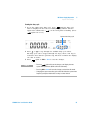
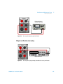
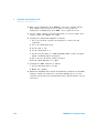
Performing resistance (2-wire) measurements
CAUTION
Disconnect circuit power and discharge all high-voltage capacitors
before measuring resistance or conductance, or testing circuit
continuity, to avoid damaging the U3606A or the device under test.
Making the connections
Connect the test leads as shown below:
Resistance
Test
current
Figure 2-3 Terminal connections for 2-wire resistance measurements
NOTE
• The U3606A will automatically select a suitable range for 2-wire
resistance measurements by default (autoranging). To manually select
a range, see “Selecting a Range” on page 54 for more information.
• The U3606A resolution is set to 5½ digits by default. To change the
resolution, see “Setting the Resolution” on page 55 for more
information.
U3606A User’s and Service Guide
33
2
Digital Multimeter Operation
Making Measurements
Measuring resistance
1 Press
to make 2- wire resistance measurements.
Table 2-5 Resistance measurement summary
Item
Description
Available ranges
100.000 Ω, 1.00000 kΩ, 10.0000 kΩ, 100.000 kΩ, 1.00000 MΩ,
10.0000 MΩ, 100.000 MΩ
Measurement method
Two-wire, open-circuit voltage limited to < 5 V
Input protection
1000 Vrms on all ranges, < 0.3 A short circuit
2 Connect the red and black test leads to input terminals
LO (black) respectively as shown in Figure 2- 3.
(red) and
3 Probe the test points and read the display.
34
U3606A User’s and Service Guide
Digital Multimeter Operation
Making Measurements
2
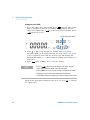
Performing low-resistance (4-wire) measurements
CAUTION
NOTE
Disconnect circuit power and discharge all high-voltage capacitors
before measuring resistance or conductance, or testing circuit
continuity, to avoid damaging the U3606A or the device under test.
DC power supply functions are locked
The DC power supply functions are locked when you select the
low-resistance (Lo Ω) measurements. You cannot use the DC power
supply module simultaneously with the digital multimeter module when
you are measuring 4-wire low-resistance measurements.
To unlock the DC power supply functions, exit the low-resistance (Lo Ω)
measurement by selecting another multimeter measurement.
For measuring low- resistance, a delayed response should be expected from
the front panel display. For remote interface operation, increase the SCPI
query timeout value. (Typically 15000 ms.)
U3606A User’s and Service Guide
35
2
Digital Multimeter Operation
Making Measurements
Making the connections
Connect the test leads as shown below:
Resistance
Test
current
Figure 2-4 Terminal connections for 4-wire resistance measurements
NOTE
• The U3606A will automatically select a suitable range for 4-wire
low-resistance measurements by default (autoranging). To manually
select a range, see “Selecting a Range” on page 54 for more
information.
• The U3606A resolution is set to 5½ digits by default. To change the
resolution, see “Setting the Resolution” on page 55 for more
information.
36
U3606A User’s and Service Guide
Digital Multimeter Operation
Making Measurements
2
Measuring low-resistance
1 Press Shift > Lo Ω to make 4- wire low- resistance measurements. (The
Lo Ω annunciator is shown on the display.)
Lo Ω annunciator
Table 2-6 Low-resistance measurement summary
Item
Description
Available ranges
100 mΩ, 1000 mΩ, 10 Ω
Measurement method
Four-wire, the test current is sent from the FORCE terminals and the
resistance is measured by the SENSE terminals.
Input protection
• FORCE terminals: 1000 Vdc on all ranges, protected with a 3.15
A/250 V FF fuse
• SENSE terminals: 1000 Vrms on all ranges, < 0.3 A short circuit
2 Connect the first red and black test leads to output terminals
(FORCE +) and
(FORCE –) respectively as shown in Figure 2- 4.
3 Connect the second red and black test leads to input terminals
(SENSE +) and LO (SENSE –) respectively as shown in Figure 2- 4.
4 Probe the test points and read the display.
U3606A User’s and Service Guide
37
2
Digital Multimeter Operation
Making Measurements
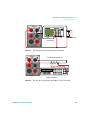
Performing frequency, pulse width, and duty cycle
measurements
There are two measuring paths for the frequency, pulse width, and duty
cycle measurements — voltage or current. Therefore, before setting the
frequency measurement, it is advisable to configure the AC voltage (see
“Measuring AC voltage” on page 27) or AC current (see “Measuring AC
(rms) current” on page 31) measurements first.
Making the connections
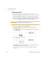
Connect the test leads as shown below:
Frequency
source
Figure 2-5 Terminal connections for frequency, pulse width, and duty cycle
measurements via the voltage path
38
U3606A User’s and Service Guide
Digital Multimeter Operation
Making Measurements
2
Frequency
source
Figure 2-6 Terminal connections for frequency, pulse width, and duty cycle measurement
via the current path
NOTE
• The range and resolution of the frequency, pulse width, and duty cycle
measurement follows the configuration of the AC voltage or AC current
measurement (dependant on the path chosen).
• The U3606A will automatically select a suitable range for AC voltage
and AC current measurements by default (autoranging). To manually
select a range, see “Selecting a Range” on page 54 for more
information.
• The U3606A resolution is set to 5½ digits by default. To change the
resolution, see “Setting the Resolution” on page 55 for more
information.
CAUTION
U3606A User’s and Service Guide
If the frequency signal measured is below 20 Hz, you must manually
set the range of the AC voltage or AC current measurement to acquire
a stable reading. To manually select a range, see “Selecting a Range” on
page 54 for more information.
39
2
Digital Multimeter Operation
Making Measurements
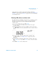
Measuring frequency — voltage path
The range and resolution of the frequency measurement via the voltage
path follows the configuration of the AC voltage measurement.
1 Press Hz ms % to make frequency measurements via the voltage path.
The AC voltage measurement display will flash briefly before the
frequency measurement display is shown.
Table 2-7 Frequency measurement (voltage path) summary
Item
Description
Available ranges
100.000 mV, 1.00000 V, 10.0000 V, 100.000 V, 750.00 V — range is
based on the voltage level of the signal, not frequency
Measurement method
Reciprocal counting technique
Signal level
0.2 V to 1.4 V
Input protection
1000 Vrms on all ranges, < 0.3 A short circuit
2 Connect the red and black test leads to input terminals V (red) and
LO (black) respectively as shown in Figure 2- 5.
3 Probe the test points and read the display.
40
U3606A User’s and Service Guide
Digital Multimeter Operation
Making Measurements
2
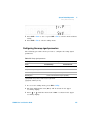
Measuring pulse width — voltage path
The range and resolution of the pulse width measurement via the voltage
path follows the configuration of the AC voltage measurement.
1 Press Hz ms % to make frequency measurements via the voltage path.
The AC voltage measurement display will flash briefly before the
frequency measurement display is shown.
2 Press Hz ms % again (until the pulse width annunciator is shown on the
display) to make pulse width measurements.
Pulse width annunciator
3 Connect the red and black test leads to input terminals V (red) and
LO (black) respectively as shown in Figure 2- 5.
4 Probe the test points and read the display.
U3606A User’s and Service Guide
41
2
Digital Multimeter Operation
Making Measurements
Measuring duty cycle — voltage path
The range and resolution of the duty cycle measurement via the voltage
path follows the configuration of the AC voltage measurement.
1 Press Hz ms % to make frequency measurements via the voltage path.
The AC voltage measurement display will flash briefly before the
frequency measurement display is shown.
2 Press Hz ms % again (until the duty cycle annunciator is shown on the
display) to make duty cycle measurements.
Duty cycle annunciator
3 Connect the red and black test leads to input terminals V (red) and
LO (black) respectively as shown in Figure 2- 5.
4 Probe the test points and read the display.
42
U3606A User’s and Service Guide
Digital Multimeter Operation
Making Measurements
2
Measuring frequency — current path
The range and resolution of the frequency measurement via the current
path follows the configuration of the AC current measurement.
1 Press
I > Hz ms % to make frequency measurements via the current
path. The AC current measurement display will flash briefly before the
frequency measurement display is shown.
Table 2-8 Frequency measurement (current path) summary
Item
Description
Available ranges
10.0000 mA, 100.000 mA, 1.00000 A, 3.0000 A — range is based on
the current level of the signal, not frequency
Measurement method
Reciprocal counting technique
Signal level
0.2 V to 1.4 V
Input protection
Protected with a 3.15 A/500 V, FF fuse
2 Connect the red and black test leads to input terminals I (red) and
LO (black) respectively as shown in Figure 2- 6.
3 Probe the test points and read the display.
U3606A User’s and Service Guide
43
2
Digital Multimeter Operation
Making Measurements
Measuring pulse width — current path
The range and resolution of the pulse width measurement via the current
path follows the configuration of the AC current measurement.
1 Press
I > Hz ms % to make frequency measurements via the current
path. The AC current measurement display will flash briefly before the
frequency measurement display is shown.
2 Press Hz ms % again (until the pulse width annunciator is shown on the
display) to make pulse width measurements.
Pulse width annunciator
3 Connect the red and black test leads to input terminals I (red) and
LO (black) respectively as shown in Figure 2- 6.
4 Probe the test points and read the display.
44
U3606A User’s and Service Guide
Digital Multimeter Operation
Making Measurements
2
Measuring duty cycle — current path
The range and resolution of the duty cycle measurement via the current
path follows the configuration of the AC current measurement.
1 Press
I > Hz ms % to make frequency measurements via the current
path. The AC current measurement display will flash briefly before the
frequency measurement display is shown.
2 Press Hz ms % again (until the duty cycle annunciator is shown on the
display) to make duty cycle measurements.
Duty cycle annunciator
3 Connect the red and black test leads to input terminals I (red) and
LO (black) respectively as shown in Figure 2- 6.
4 Probe the test points and read the display.
U3606A User’s and Service Guide
45
2
Digital Multimeter Operation
Making Measurements
Performing capacitance measurements
The U3606A Multimeter|DC Power Supply calculates capacitance by
charging a capacitor with a known current for a period of time, and then
measuring the voltage.
Measuring tips:
• For measuring capacitance values greater than 10000 μF, discharge the
capacitor first, then select a suitable range for measurement. This will
speed up the measurement time and also ensure that the correct
capacitance value is obtained.
• For measuring capacitance values greater than 1 mF, a delayed
response should be expected from the front panel display. For remote
interface operation, increase the SCPI query timeout value. (Typically >
10000 ms.)
• For measuring small capacitance values, press Null with the test leads
open to subtract the residual capacitance of the instrument and leads.
CAUTION
46
Disconnect circuit power and discharge all high-voltage capacitors
before measuring capacitance to avoid damaging the U3606A or the
device under test. To confirm that a capacitor has fully discharged, use
the DC voltage measurement. See “Measuring DC voltage” on page 26
for more information.
U3606A User’s and Service Guide
Digital Multimeter Operation
Making Measurements
2
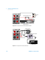
Making the connections
Connect the test leads as shown below:
–
Capacitance
+
Figure 2-7 Terminal connections for capacitance measurements
NOTE
• The U3606A will automatically select a suitable range for capacitance
measurements by default (autoranging). To manually select a range,
see “Selecting a Range” on page 54 for more information.
• The resolution for capacitance measurement is fixed to 3½ digits.
U3606A User’s and Service Guide
47
2
Digital Multimeter Operation
Making Measurements
Measuring capacitance
1 Press
to make capacitance measurements.
Table 2-9 Capacitance measurement summary
Item
Description
Available ranges
1 nF, 10 nF, 100 nF, 1 μF, 10 μF, 100 μF, 1000 μF, 10000 μF
Measurement method
Computed from constant current source charge time, typical 0.2 V to
1.4 Vac signal level
Input protection
1000 Vrms on all ranges, < 0.3 A short circuit
2 Connect the red and black test leads to input terminals
LO (black) respectively (refer to Figure 2- 7 on page 47).
(red) and
3 Probe the test points and read the display.
48
U3606A User’s and Service Guide
Digital Multimeter Operation
Making Measurements
2
Performing continuity tests
CAUTION
Disconnect circuit power and discharge all high-voltage capacitors
before measuring resistance or conductance, or testing circuit
continuity, to avoid damaging the U3606A or the device under test.
Making the connections
Connect the test leads as shown below:
Open or
closed
circuit
Test
current
Figure 2-8 Terminal connections for continuity tests
NOTE
• The U3606A will automatically select a suitable range for continuity
measurements by default (autoranging). To manually select a range,
see “Selecting a Range” on page 54 for more information.
• The resolution for continuity tests is fixed to 3½ digits.
U3606A User’s and Service Guide
49
2
Digital Multimeter Operation
Making Measurements
Testing continuity
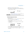
1 Press
again (until the continuity annunciator is shown on the
display) to make continuity measurements.
Continuity annunciator
Table 2-10 Continuity function summary
Item
Description
Measurement method
0.83 mA ± 0.2% constant current source, open-circuit voltage limited
to < 5 V
Audible tone:
Continuous beep when reading is less than threshold resistance of
10 Ω at 1.0 kΩ range
Input protection
1000 Vrms on all ranges, < 0.3 A short circuit
2 Connect the red and black test leads to input terminals
LO (black) respectively as shown in Figure 2- 8.
(red) and
3 Probe the test points. The instrument beeps when the continuity
measurement is less than or equal to the continuity threshold.
50
U3606A User’s and Service Guide
Digital Multimeter Operation
Making Measurements
2
Performing diode tests
CAUTION
Disconnect circuit power and discharge all high-voltage capacitors
before checking diodes to avoid damaging the U3606A or the device
under test.
Making the connections
Connect the test leads as shown below:
–
Forward
bias diode
+
Test
current
–
Reverse
bias diode
+
Test
current
Figure 2-9 Terminal connections for diode tests
U3606A User’s and Service Guide
51
2
Digital Multimeter Operation
Making Measurements
NOTE
The resolution for diode tests is fixed to 3½ digits.
Checking diodes
1 Press
again (until the diode annunciator is shown on the
display) to make diode measurements.
Diode annunciator
Table 2-11 Diode function summary
Item
Description
Measurement method
0.83 mA ± 0.2% constant current source
Audible tone:
• Continuous beep when level is below +50 mV DC
• Single tone for normal forward-biased diode or semiconductor
junction where 0.3 V ¤ reading ¤ 0.8 V
Input protection
1000 Vrms on all ranges, < 0.3 A short circuit
2 Connect the red and black test leads to input terminals
LO (black) respectively.
(red) and
3 Connect the other end of the red test lead to the positive terminal
(anode) of the diode and the black test lead to the negative terminal
(cathode). Refer to Figure 2- 9 on page 51.
NOTE
The cathode of a diode is indicated with a band.
4 Read the display.
52
U3606A User’s and Service Guide
Digital Multimeter Operation
Making Measurements
NOTE
2
The U3606A can display diode forward bias of up to approximately
1.2 V. The forward bias of a typical diode is within the range of 0.3 V to
0.8 V.
5 Reverse the probes and measure the voltage across the diode again
(refer to Figure 2- 9 on page 51). Assess the diode according to the
following guidelines:
• A diode is considered good if the multimeter displays “OPEn” in
reverse bias mode.
• A diode is considered shorted if the multimeter displays
approximately 0 V in both forward and reverse bias modes, and the
U3606A beeps continuously.
• A diode is considered open if the multimeter displays “OPEn” in both
forward and reverse bias modes.
U3606A User’s and Service Guide
53
2
Digital Multimeter Operation
Selecting a Range
Selecting a Range
You can allow the U3606A to automatically select the range using
autoranging, or you can select a fixed range using manual ranging.
Autoranging is convenient because the U3606A automatically selects the
appropriate range for sensing and displaying each measurement. However,
manual ranging results in better performance, since the U3606A does not
have to determine which range to use for each measurement.
Key
Description
Press
to select a higher range and disable autoranging.
Press
to select a lower range and disable autoranging.
Press Shift > Auto to enable autoranging and disable manual ranging.
• Autoranging is selected at default factory power- on and after a remote
reset.
• Manual ranging — If the input signal is greater than can be measured
on the selected range, the multimeter provides these overload
indications: “OL” from the front panel or “±9.9E+37” from the remote
interface.
• For frequency, pulse width, and duty cycle measurements, ranging
applies to the input voltage or input current of the signal, not its
frequency.
• The range is fixed for diode (1 Vdc range) tests.
• The U3606A remembers the selected ranging method (auto or manual)
and the selected manual range for each measurement function.
• Autorange thresholds — The U3606A shifts ranges as follows:
• Down range at < 10% of current range
• Up range at > 120% of current range
54
U3606A User’s and Service Guide
Digital Multimeter Operation
Setting the Resolution
2
Setting the Resolution
You can select either 4½ digit or 5½ digit resolution for the AC voltage,
DC voltage, AC+DC voltage, AC current, DC current, AC+DC current,
2- wire resistance, and 4- wire low- resistance measurements.
• 5½ digit readings have the best accuracy and noise rejection.
• 4½ digit readings provide for faster readings.
• The range and resolution of the frequency, pulse width, and duty cycle
measurements follows the configuration of the AC voltage or the AC
current function.
• Continuity and diode tests have a fixed 4½ digit display.
• Capacitance measurements have a fixed 3½ digit display.
Key
Description
Press Shift > 4½ 5½ to toggle between 4½ digit and 5½ digit mode.
U3606A User’s and Service Guide
55
2
Digital Multimeter Operation
Math Operations
Math Operations
The U3606A Multimeter|DC Power Supply provides six math operations:
null measurements, dB measurements, dBm measurements, statistics
(MinMax) for accumulated readings, limit testing, and a hold function. The
table below describes the math operations that can be used with each
measurement function.
Table 2-12 Math operations summary
Measurement
functions
Allowed math operations
Null
dBm
dB
MinMax
Limit
Hold
DC voltage
✔
✔
✔
✔
✔
✔
DC current
✔
-
-
✔
✔
✔
AC voltage
✔
✔
✔
✔
✔
✔
AC current
✔
-
-
✔
✔
✔
Resistance (2-wire)
✔
-
-
✔
✔
✔
Low-resistance (4-wire)
✔
-
-
✔
✔
✔
Frequency
✔
-
-
✔
✔
✔
Pulse width
✔
-
-
✔
✔
✔
Duty cycle
✔
-
-
✔
✔
✔
Capacitance
✔
-
-
✔
✔
✔
Continuity
-
-
-
-
-
-
Diode
-
-
-
-
-
-
• All math operations can be toggled off by pressing Shift > Exit.
• All math operations are automatically turned- off when changing
measuring functions.
• Range changing is allowed for all math operations.
• For remote operation, refer to the CALCulate subsystem in the U3606A
Programmer’s Reference.
56
U3606A User’s and Service Guide
Digital Multimeter Operation
Math Operations
2
Null
When making null measurements, also called relative, each reading is the
difference between a stored (selected or measured) null value and the
input signal. One possible application is to increase the accuracy of a
2- wire resistance measurement by nulling the test lead resistance. Nulling
the leads is also particularly important prior to making capacitance
measurements. The formula used for calculating null measurements is:
Result = reading – null value
The null value is adjustable, you can set it to any value between 0 and
±120% of the highest range, for the present function.
NOTE
Null can be set for both auto and manual range settings, but not in the
case of an overload.
Enabling the null operation
For any measurement function, you can directly measure and store the
null value by pressing Null with the test leads open (nulls the test lead
capacitance), shorted (nulls the test lead resistance), or across a desired
null value circuit.
The Null annunciator is illuminated and the null operation is enabled.
Null annunciator
Press Shift > Exit to exit the null mode.
U3606A User’s and Service Guide
57
2
Digital Multimeter Operation
Math Operations
Editing the null value
1 Press Null again to view and edit the null value.
2 Press
or
to select which digit position or range to be changed.
3 Press
or
to increase or decrease the value.
4 Press Shift > Save to save the changes. “donE” will be briefly displayed
in the upper secondary display. The display will then return to normal.
5 Press Shift > Exit to exit the edit mode without saving.
NOTE
• In resistance measurement, the U3606A will read a non-zero value
even when the two test leads are in direct contact, because of the
resistance of these leads. Use the null function to zero-adjust the
display.
• In DC voltage measurement mode, the thermal effect will influence the
accuracy. Short the test leads and press Null once the displayed value
is stable to zero-adjust the display.
58
U3606A User’s and Service Guide
Digital Multimeter Operation
Math Operations
2
dBm measurements
The logarithmic dBm (decibels relative to 1 mW) scale is often used in RF
signal measurements. The U3606A takes a measurement and calculates the
power delivered to a reference resistance (typically 50 Ω, 75 Ω, or 600 Ω).
Voltage measurement is then converted to dBm.
NOTE
This math operation applies to voltage measurements only.
The dBm function is logarithmic, and is based on a calculation of power
delivered to a reference resistance, relative to 1 mW. The formula used for
calculating dBm measurements is:
2
dBm = 10 × log 10 ( reading ⁄ ( reference resis tan ce ) ⁄ ( 1 mW ) )
You can select the reference resistance value through the utility menu. The
default settings is 600 Ω. See “Selecting a dBm reference resistance
value” on page 121 for more information.
Enabling the dBm operation
Press Shift > dBm to enable the dBm operation.
The dBm annunciator is illuminated and the dBm function is enabled.
dBm annunciator
Press Shift > dBm again or Shift > Exit to exit the dBm mode.
U3606A User’s and Service Guide
59
2
Digital Multimeter Operation
Math Operations
dB measurements
Each dB measurement is the difference between the input signal and a
stored relative value, with both values converted to dBm. When enabled,
the dB operation computes the dBm value for the next reading, stores the
dBm result into the relative value register and immediately produces the
dB calculation. The formula used for calculating dB measurements is:
dB = reading in dBm – relative value in dBm
The relative value can take any value between 0 dBm and ±120.000 dBm.
The default relative value is 0 dBm. You can either let the instrument
automatically measure this value, or you can enter a specific value.
NOTE
This math operation applies to voltage measurements only.
Enabling the dB operation
Press Shift > dBm > dB to enable the dB operation. The first displayed
reading is always precisely 00.000 dB.
The dB annunciator is illuminated and the dB function is enabled.
dB annunciator
Press Shift > Exit to exit the dB mode.
60
U3606A User’s and Service Guide
Digital Multimeter Operation
Math Operations
2
Editing the relative value
1 Press dB again to view and edit the relative value.
2 Press
or
to select which digit position or range to be changed.
3 Press
or
to increase or decrease the value.
4 Press Shift > Save to save the changes. “donE” will be briefly displayed
in the upper secondary display. The display will then return to normal.
5 Press Shift > Exit to exit the edit mode without saving.
U3606A User’s and Service Guide
61
2
Digital Multimeter Operation
Math Operations
MinMax
The MinMax operation stores the minimum and maximum values, the
average, and the number of readings during a series of measurements.
From the front panel, you can view the following statistical data for any
set of readings: average or mean (Avg), maximum (Max), and minimum
(Min).
NOTE
• This math operation applies to all measurement functions except
continuity and diode test.
• The stored statistical data are cleared when statistics are enabled,
when the CALculate:FUNCtion command is sent while the
CALCulate:STATe is ON, when the power is turned off, after a
Factory Reset (*RST command), after an Instrument Preset
(SYSTem:PRESet command), or after a measurement function
change.
• The average function can be restarted by pressing MinMax for more
than one second.
Enabling the MinMax operation
Press MinMax to enable the MinMax operation.
The Max annunciator is illuminated and the U3606A begins accumulating
various statistics about the readings being displayed.
Max annunciator
Press MinMax again to step through the maximum reading (the Max
annunciator is illuminated), minimum reading (the Min annunciator is
illuminated), average reading (the Avg annunciator is illuminated), or
present reading (the MaxMinAvg annunciator is illuminated).
62
U3606A User’s and Service Guide
Digital Multimeter Operation
Math Operations
2
Each time a new minimum, maximum, or average value is stored, the
instrument beeps once (if the beeper is enabled). The U3606A calculates
the average of all readings and records the number of readings taken since
the MinMax function was enabled.
Accumulated statistics are:
• Max: maximum reading since the MinMax function was enabled
• Min: minimum reading since the MinMax function was enabled
• Avg: average of all readings since the MinMax function was enabled
• MaxMinAvg: present reading (actual input signal value)
Press Shift > Exit to exit the MinMax mode.
U3606A User’s and Service Guide
63
2
Digital Multimeter Operation
Math Operations
Limit
The limit test function enables you to perform pass or fail testing to upper
and lower limits that you specify. You can set the upper and lower limits
to any value between 0 and ±120% of the highest range for the present
measurement function. The upper limit value you select must be larger
than the lower limit value. The initial factory settings for both values is
zero.
NOTE
• This math operation applies to all measurement functions except
continuity and diode test.
• The instrument clears all limits after a Factory Reset (*RST command)
or an Instrument Preset (SYSTem:PRESet command), or when a
measurement function is changed.
Enabling the limit operation
Press Shift > Limit to enable the limit operation.
The Limit annunciator is illuminated and the limit function is enabled.
Limit annunciator
64
U3606A User’s and Service Guide
Digital Multimeter Operation
Math Operations
2
The primary display briefly shows “PASS” when readings are within the
specified limits, “HI” when the reading is above the high limit, and “LO”
when the reading is below the low limit.
Each time the input value transitions from “PASS” to “HI” or from “PASS”
to “LO”, or when transitioning directly from “HI” to “LO” or “LO” to “HI”,
the instrument beeps once (if the beeper is enabled).
Press Shift > Exit to exit the limit mode.
U3606A User’s and Service Guide
65
2
Digital Multimeter Operation
Math Operations
Editing the upper and lower limit values
1 Press Shift > Limit again to view and edit the upper (HI) and lower (LO)
limit values.
2 Press
or
to toggle between the upper (HI) limit value and the
lower (LO) limit value
3 Press
or
to begin editing the upper or lower limit value selected.
4 Press
or
to select which digit position or range to be changed.
You may also toggle between the upper (HI) and lower (LO) limit values
by positioning your cursor on the “HI” or “LO” message shown in the
lower secondary display.
5 Press
or
to increase or decrease the value.
6 Press Shift > Save to save the changes. The display will automatically
revert to the next limit display.
For example, if you press Shift > Save after editing the upper limit (HI)
value, the instrument will save your specified value, and switch to the
lower limit (LO) display. Pressing Shift > Save again will once again save
your specified value, and switch the display back to the upper limit
(HI) display.
7 Press Shift > Exit to exit the edit mode. The display will also return to
normal after a few seconds of inactivity.
66
U3606A User’s and Service Guide
Digital Multimeter Operation
Math Operations
2
Hold
The refresh hold feature allows you to capture and hold a reading, within
the specified variation and threshold values, on the front panel display.
This is useful in situations when you want to take a reading, remove the
test probes, and have the reading remain on the display.
When a stable reading is detected, the instrument beeps once (if the
beeper is enabled), and holds the reading on the primary display. You can
select the variation through the utility menu. The default settings is 10% of
the full scale.
A new reading value is updated in the primary display when the variation
of the measured value exceeds the variation preset in the utility menu.
The instrument beeps once (if the beeper is enabled) when a reading
value is updated. See “Enable refresh hold” on page 130 for more
information on configuring the refresh hold settings.
For voltage, current, and capacitance measurements, the reading value will
not be updated when the reading falls below the threshold preset in the
utility menu.
For continuity and diode tests, the reading value will not be updated
when an open state is detected.
NOTE
If the reading value is unable to reach a stable state (when exceeding the
preset variation), the reading value will not be updated.
Set the variation to “OFF” in the utility menu to enable data hold. See
“Enable data hold” on page 131 for more information. In data hold mode,
the reading is not updated even if the input signal value changes. The
reading held will remain on the display until you exit the hold mode.
U3606A User’s and Service Guide
67
2
Digital Multimeter Operation
Math Operations
Enabling the hold operation
Press Hold to enable the hold operation.
The Hold annunciator is illuminated and the hold function is enabled.
Hold annunciator
Press Hold again or Shift > Exit to exit the hold mode.
68
U3606A User’s and Service Guide
Digital Multimeter Operation
Triggering the Multimeter
2
Triggering the Multimeter
The U3606A Multimeter|DC Power Supply triggering system allows you to
generate triggers either automatically or manually via the Trig key on the
front panel or the *TRG command via the remote interface.
From the front panel (local interface), the multimeter always auto- triggers
by default. Auto triggering takes continuous readings at the fastest rate
possible for the selected measurement configuration.
You can enable the single trigger function to manually trigger the U3606A
readings. See “Front panel triggering” on page 70 for more information on
the single trigger function.
From the remote interface, triggering the U3606A is a three- step process:
1 Configure the U3606A for measurement by selecting the function, range,
resolution, and so on.
2 Specify the U3606A trigger source. The U3606A Multimeter|DC Power
Supply will accept a software (bus) command or an immediate
(continuous) trigger.
3 Ensure that the U3606A is ready to accept a trigger from the specified
source (called the “wait- for- trigger” state).
See “Remote interface triggering” on page 71 for more information on the
software (bus) or immediate triggering source.
U3606A User’s and Service Guide
69
2
Digital Multimeter Operation
Triggering the Multimeter
Front panel triggering
Single triggering
The U3606A takes one reading each time you press Trig.
NOTE
The single trigger mode is available from the local interface only.
Press Shift > Trig once to enable the single trigger mode.
The Trig annunciator is illuminated and the single trigger function is
enabled.
Trig annunciator
A single reading is taken, and another reading is taken each time you
press Trig. (You do not need to press Shift again.)
Press Shift > Trig again to exit the single trigger mode.
70
U3606A User’s and Service Guide
Digital Multimeter Operation
Triggering the Multimeter
2
Remote interface triggering
Immediate triggering
In the immediate trigger mode, the trigger signal is always present. When
you place the multimeter in the wait- for- trigger state, the trigger is issued
immediately. This is the default trigger source for the U3606A
Multimeter|DC Power Supply.
NOTE
The immediate trigger mode is available from the remote interface only.
Remote interface operation:
• The TRIGger:SOURce IMMediate command selects the immediate
trigger source:
• After selecting the trigger source, you must place the instrument in the
“wait- for- trigger” state using the INITiate[:IMMediate] or READ?
command. A trigger will not be accepted from the selected trigger
source until the instrument is in the “wait- for- trigger” state.
Refer to the U3606A Programmer’s Reference for the syntax and complete
descriptions for these commands.
Software (bus) triggering
The bus trigger mode corresponds in function as the Single triggering
mode, except the trigger is initiated by sending a bus trigger command,
after selecting BUS as the trigger source.
NOTE
U3606A User’s and Service Guide
The bus trigger mode is available from the remote interface only.
71
2
Digital Multimeter Operation
Triggering the Multimeter
Remote interface operation:
• The TRIGger:SOURce BUS command selects the bus trigger source.
• The MEASure? command overwrites the bus trigger and triggers the
U3606A and returns a measurement.
• The READ? command does not overwrite the bus trigger, and if selected,
generates an error. It will only trigger the instrument and return a
measurement when the IMMEdiate trigger is selected.
• The INITiate command only initiates the measurement and needs a
trigger (*TRG command) to make the actual measurement.
Refer to the U3606A Programmer’s Reference for the syntax and complete
descriptions for these commands.
72
U3606A User’s and Service Guide
U3606A Multimeter|DC Power Supply
User’s and Service Guide
3
DC Power Supply Operation
Basic Operation 74
Constant voltage (CV) mode
Constant current (CC) mode
Protection Functions 78
Overvoltage protection (OVP)
Overcurrent protection (OCP)
Overvoltage limit (OV) 84
Overcurrent limit (OC) 86
Square-wave Output 88
Sweep Functions 93
Ramp signal 93
Scan signal 95
Selecting a Range 97
Enabling the Output 98
Remote Sensing 99
74
76
78
81
This chapter contains examples on how to operate the DC power supply
from the front panel. The simple examples discussed in this chapter shows
you how to program the output voltage and current functions, the
protection functions, and the additional source functions.
Agilent Technologies
73
3
DC Power Supply Operation
Basic Operation
Basic Operation
The U3606A has two basic operating modes: constant voltage and constant
current mode. In constant voltage mode, the U3606A regulates the output
voltage at the selected value, while the load current varies as required by
the load. In constant current mode, the U3606A regulates the output
current at the selected value, while the voltage varies as required by the
load.
The U3606A is also capable of generating square waves with selectable
frequency, pulse width, and duty cycle values.
Constant voltage (CV) mode
Making the connections
Connect the load as shown below:
LOAD
Figure 3-1 Constant voltage mode terminal connections
74
U3606A User’s and Service Guide
DC Power Supply Operation
Basic Operation
3
Supplying constant voltage
1 Press Voltage to select the constant voltage mode. When the U3606A is
operating in constant voltage mode, the CV annunciator on the front
panel is illuminated.
CV annunciator
2 The output voltage can be programmed when the output is enabled
(OUT) or disabled (SBY). Ensure that the CV annunciator is flashing.
(Press Voltage again if it is not.)
3 Press
or
to select which digit position to be changed.
4 Press
or
to increase or decrease the value.
5 Press Voltage again, Shift > Save, or Shift > Exit to save the changes and
exit the edit mode.
6 Press
OUT
S BY
NOTE
U3606A User’s and Service Guide
to regulate the output voltage.
The output voltage is limited by the range selected. Press Shift > Range to
select an appropriate range. You can only select a range when the output
is disabled (the SBY annunciator is illuminated).
75
3
DC Power Supply Operation
Basic Operation
Constant current (CC) mode
Making the connections
Connect the load as shown below:
LOAD
Figure 3-2 Constant current mode terminal connections
76
U3606A User’s and Service Guide
DC Power Supply Operation
Basic Operation
3
Supplying constant current
1 Press Current to select the constant current mode. When the U3606A is
operating in constant current mode, the CC annunciator on the front
panel is illuminated.
CC annunciator
2 The output current can be programmed when the output is enabled
(OUT) or disabled (SBY). Ensure that the CC annunciator is flashing.
(Press Current again if it is not.)
3 Press
or
to select which digit position to be changed.
4 Press
or
to increase or decrease the value.
5 Press Current again, Shift > Save, or Shift > Exit to save the changes and
exit the edit mode.
6 Press
OUT
S BY
NOTE
U3606A User’s and Service Guide
to regulate the output current.
The output current is limited by the range selected. Press Shift > Range to
select an appropriate range. You can only select a range when the output
is disabled (the SBY annunciator is illuminated).
77
3
DC Power Supply Operation
Protection Functions
Protection Functions
Overvoltage protection (OVP)
In constant current mode, the U3606A regulates the output current at the
selected value, while the voltage varies as required by the load. The
overvoltage protection protects against overvoltage conditions on the
output. If the load attempts to draw more voltage than required, such that
it exceeds the programmed protection value, the overvoltage protection
circuit will protect the load by disabling the output.
The following steps shows you how to set the OVP trip level, how to check
OVP operation, and how to clear the OVP condition.
NOTE
Setting the OVP trip level will not activate the OVP feature. To activate the
OVP feature, you will need to enable the output protection state from the
utility menu. See Chapter 4, “Setting the output protection state,” starting
on page 122 for more information.
Setting the OVP trip level
1 The OVP trip level can be programmed when the output is enabled
(OUT) or disabled (SBY). Ensure that the U3606A is operating in
constant current mode. (The CC annunciator is illuminated.) Press Shift
> Protect to enter the OVP edit menu.
2 Press
or
to select which digit position to be changed.
3 Press
or
to increase or decrease the value. The OVP value is set
to the maximum protection limits by default.
• 33.000 V when range S1 is selected, and
• 8.8000 V when range S2 is selected.
78
U3606A User’s and Service Guide
DC Power Supply Operation
Protection Functions
3
4 Press Shift > Save or Voltage (Protect) to save the changes. “donE” will be
briefly displayed in the upper secondary display. The display will then
return to normal.
5 Alternatively, press Shift > Exit or Shift > Protect to exit the edit mode
without saving.
NOTE
• The OVP feature is always enabled by default whenever you select
constant current mode. You can disable the OVP feature by disabling
the output protection state from the utility menu. See Chapter 4,
“Setting the output protection state,” starting on page 122 for more
information.
• If the OVP value is set to a lesser value than the OV value, the OV value
will be adjusted to equal the OVP value.
• The OVP value is not applicable for square-wave output.
• The OVP value is limited by the range selected. Press Shift > Range to
select an appropriate range. You can only select a range when the
output is disabled (the SBY annunciator is illuminated).
Checking the OVP operation
To check OVP operation, raise the regulated output current slowly. Watch
the voltage drawn by the load as it reaches near the trip point. Then very
gradually increase the output current using the directional keys until the
OVP circuit trips. This will disable the U3606A output, cause the CC
annunciator to flash, and the OV and Error annunciator to illuminate.
The “triP” message appears on the display after a few seconds of
inactivity.
U3606A User’s and Service Guide
79
3
DC Power Supply Operation
Protection Functions
Error number 510, “Voltage output over protection” will be recorded in the
error queue when the OVP circuit trips. To read and clear the error
message, see “Reading error messages” on page 114. For a complete list
of all error messages, see Chapter 9, “List of Error Messages,” starting on
page 259.
NOTE
Resetting the OVP condition
Use one of the following methods to reset the OVP circuit after it
activates. If the condition that caused the overvoltage shutdown is still
present, the OVP circuit will turn the output off again.
1 When the OVP circuit trips, the U3606A will immediately prompt you to
change the OVP trip level. Use the directional keys to select a higher
OVP trip level and press Shift > Save or Voltage (Protect) to save the
changes.
2 Alternatively, press Shift > Exit or Shift > Protect to exit the edit mode
without changing the OVP trip level.
3 You may read and clear the error message by accessing the utility
menu. See “Reading error messages” on page 114 for more information.
4 Press
OUT
S BY
to turn the output on.
5 If the OVP continues to trip, try lowering the regulated output current,
or raising the OVP trip level.
80
U3606A User’s and Service Guide
DC Power Supply Operation
Protection Functions
3
Overcurrent protection (OCP)
In constant voltage mode, the U3606A regulates the output voltage at the
selected value, while the load current varies as required by the load. The
overcurrent protection will disable the output if the load effect exceeds
the programmed protection value. This protection is useful when the load
is sensitive to an overcurrent condition.
The following steps shows you how to set the OCP trip level, how to check
OCP operation, and how to clear the OCP condition.
NOTE
Setting the OCP trip level will not activate the OCP feature. To activate the
OCP feature, you will need to enable the output protection state from the
utility menu. See Chapter 4, “Setting the output protection state,” starting
on page 122 for more information.
Setting the OCP trip level
1 The OCP trip level can be programmed when the output is enabled
(OUT) or disabled (SBY). Ensure that the U3606A is operating in
constant voltage mode. (The CV annunciator is illuminated.) Press Shift
> Protect to enter the OCP edit menu.
2 Press
or
to select which digit position to be changed.
3 Press
or
to increase or decrease the value. The OCP value is set
to the maximum protection limits by default.
• 1.1000 A when range S1 is selected, and
• 3.3000 A when range S2 is selected.
4 Press Shift > Save or Voltage (Protect) to save the changes. “donE” will be
briefly displayed in the upper secondary display. The display will then
return to normal.
5 Alternatively, press Shift > Exit or Shift > Protect to exit the edit mode
without saving.
U3606A User’s and Service Guide
81
3
DC Power Supply Operation
Protection Functions
NOTE
• The OCP feature is always enabled by default whenever you select
constant voltage mode. You can disable the OCP by disabling the output
protection state from the utility menu. See Chapter 4, “Setting the
output protection state,” starting on page 122 for more information.
• If the OCP value is set to a lesser value than the OC value, the OC value
will be adjusted to equal the OCP value.
• The OCP value is not applicable for square-wave output.
• The OCP value is limited by the range selected. Press Shift > Range to
select an appropriate range. You can only select a range when the
output is disabled (the SBY annunciator is illuminated).
Checking the OCP operation
To check OCP operation, raise the regulated output voltage slowly. Watch
the current drawn by the load as it reaches near the trip point. Then very
gradually increase the output voltage using the directional keys until the
OCP circuit trips. This will disable the U3606A output, cause the CV
annunciator to flash, and the OC and Error annunciator to illuminate.
The “triP” message appears on the display after a few seconds of
inactivity.
NOTE
82
Error number 511, “Current output over protection” will be recorded in the
error queue when the OCP circuit trips. To read and clear the error
message, see “Reading error messages” on page 114. For a complete list
of all error messages, see Chapter 9, “List of Error Messages,” starting on
page 259.
U3606A User’s and Service Guide
DC Power Supply Operation
Protection Functions
3
Resetting the OCP condition
Use one of the following methods to reset the OCP circuit after it
activates. If the condition that caused the overcurrent shutdown is still
present, the OCP circuit will turn the output off again.
1 When the OCP circuit trips, the U3606A will immediately prompt you to
change the OCP trip level. Use the directional keys to select a higher
OCP trip level and press Shift > Save or Voltage (Protect) to save the
changes.
2 Alternatively, press Shift > Exit or Shift > Protect to exit the edit mode
without changing the OCP trip level.
3 You may read and clear the error message by accessing the utility
menu. See “Reading error messages” on page 114 for more information.
4 Press
OU T
S BY
to turn the output on.
5 If the OCP continues to trip, try lowering the regulated output current,
or raising the OCP trip level.
U3606A User’s and Service Guide
83
3
DC Power Supply Operation
Protection Functions
Overvoltage limit (OV)
The overvoltage limit prevents the output voltage present across the load
to change beyond the programmed overvoltage limit. If the load effect
exceeds the programmed overvoltage limit, the CC output will be lowered
to maintain the output power across the load. The combination of the OV
and OVP features create a closed loop circuit protection for sensitive load
behaviors.
Setting the OV level
The OV level can be programmed when the output is enabled (OUT) or
disabled (SBY). Ensure that the U3606A is operating in constant current
mode. (The CC annunciator is illuminated.)
1 Press Shift > Limit to enter the OV edit menu.
2 Press
or
to select which digit position to be changed.
3 Press
or
to increase or decrease the value. The OV value is set
to the maximum protection limits by default.
• 30.000 V when range S1 is selected, and
• 8.000 V when range S2 is selected.
4 Press Shift > Save or Current (Limit) to save the changes. “donE” will be
briefly displayed in the upper secondary display. The display will then
return to normal.
5 Alternatively, press Shift > Exit or Shift > Limit to exit the edit mode
without saving.
84
U3606A User’s and Service Guide
DC Power Supply Operation
Protection Functions
NOTE
3
• The OV limit feature is always enabled by default whenever you select
constant current mode. You cannot disable the OV limit feature.
• If the OV value is set to a greater value than the OVP value, the OVP
value will be adjusted to equal the OV value.
• If the OV value is set to zero, this will result in the output current being
dropped to zero for limiting.
• The OV value is not applicable for square-wave output.
• The OV value is limited by the range selected. Press Shift > Range to
select an appropriate range. You can only select a range when the
output is disabled (the SBY annunciator is illuminated).
U3606A User’s and Service Guide
85
3
DC Power Supply Operation
Protection Functions
Overcurrent limit (OC)
The overcurrent limit prevents the output current flowing through the load
to change beyond the programmed overcurrent limit. If the load effect
exceeds the programmed overcurrent limit, the CV output will be lowered
to maintain the output power across the load. The combination of the OC
and OCP features create a closed loop circuit protection for sensitive load
behaviors.
Setting the OC level
The OC level can be programmed when the output is enabled (OUT) or
disabled (SBY). Ensure that the U3606A is operating in constant voltage
mode. (The CV annunciator is illuminated.)
1 Press Shift > Limit to enter the OC edit menu.
2 Press
or
to select which digit position to be changed.
3 Press
or
to increase or decrease the value. The OC value is set
to the maximum protection limits by default.
• 1.0000 A when range S1 is selected, and
• 3.0000 A when range S2 is selected.
4 Press Shift > Save or Current (Limit) to save the changes. “donE” will be
briefly displayed in the upper secondary display. The display will then
return to normal.
5 Alternatively, press Shift > Exit or Shift > Limit to exit the edit mode
without saving.
86
U3606A User’s and Service Guide
DC Power Supply Operation
Protection Functions
NOTE
3
• The OC limit feature is always enabled by default whenever you select
constant voltage mode. You cannot disable the OC limit feature.
• If the OC value is set to a greater value than the OCP value, the OCP
value will be adjusted to equal the OC value.
• If the OC value is set to zero, this will result in the output voltage being
dropped to zero for limiting.
• The OC value is not applicable for square-wave output.
• The OC value is limited by the range selected. Press Shift > Range to
select an appropriate range. You can only select a range when the
output is disabled (the SBY annunciator is illuminated).
U3606A User’s and Service Guide
87
3
DC Power Supply Operation
Square-wave Output
Square-wave Output
Square- wave output is a unique function for many applications, such as
pulse width modulation (PWM) output, adjustable voltage control, and
synchronous clock (baud rate generator). You can also use this function to
check and calibrate flow- meter displays, counters, tachometers,
oscilloscopes, frequency converter, frequency transmitter, and other
frequency input devices.
Selecting square-wave output
1 Press
to select the square- wave mode. When the U3606A is
operating in the square- wave mode, the square- wave annunciator
(
) on the front panel is illuminated.
Square-wave annunciator
2 The default frequency is 600
display. Press
again to
and pulse width values. (The
cycle is 50%, and the default
Hz, as shown on the upper secondary
cycle through the amplitude, duty cycle,
default amplitude is 0 V, the default duty
pulse width is 0.8333 ms.)
3 The square- wave amplitude, frequency, pulse width, and duty cycle can
be set when the output is enabled (OUT) or disabled (SBY). Ensure that
the square- wave annunciator (
) is flashing to edit the amplitude,
frequency, pulse width, and duty cycle values. (Press
again if it is
not.)
88
U3606A User’s and Service Guide
DC Power Supply Operation
Square-wave Output
3
Setting the amplitude
1 To set the square- wave amplitude, press
until the amplitude value
is displayed in the lower secondary display. Ensure that the
square- wave annunciator (
) on the front panel is flashing. (Press
again if it is not.)
Square-wave amplitude
2 Press
or
to select which digit position to be changed.
3 Press
or
to increase or decrease the value.
4 Press
NOTE
again or Shift > Save to save the changes.
• Pressing
again will save the changes, and display the next
square-wave parameter. (While still in the edit mode.)
• Pressing Shift > Save will save the changes, and exit the edit mode.
• The square-wave amplitude is limited by the range selected. Press
Shift > Range to select an appropriate range. You can only select a
range when the output is disabled (the SBY annunciator is illuminated).
U3606A User’s and Service Guide
89
3
DC Power Supply Operation
Square-wave Output
Setting the frequency
1 To set the square- wave frequency, press
until the duty cycle or
pulse width value is displayed in the lower secondary display. Ensure
that the square- wave annunciator (
) on the front panel is flashing.
(Press
again if it is not.)
Square-wave frequency
Ensure that either the
duty cycle or pulse width
value is displayed here
2 Press
or
to step through the available frequencies. (There are 27
frequencies choose from.)
Table 3-1 Available frequencies for square-wave output
Frequency (Hz)
0.5, 2, 5, 6, 10, 15, 25, 30, 40, 50, 60, 75, 80, 100, 120, 150, 200, 240, 300, 400, 480, 600, 800, 1200,
1600, 2400, 4800
3 Press
NOTE
again or Shift > Save to save the changes.
• Pressing
again will save the changes, and display the next
square-wave parameter. (While still in the edit mode.)
• Pressing Shift > Save will save the changes, and exit the edit mode.
• Changing the square-wave frequency value will affect the square-wave
duty cycle and pulse width values as they are inter-related.
90
U3606A User’s and Service Guide
DC Power Supply Operation
Square-wave Output
3
Setting the duty cycle
1 To set the square- wave duty cycle, press
until the duty cycle
value is displayed in the lower secondary display. Ensure that the
square- wave annunciator (
) on the front panel is flashing. (Press
again if it is not.)
Square-wave duty cycle
2 Press
or
to step through the available duty cycle values.
The duty cycle can be stepped through 256 steps, where each step is
0.390625% more than the previous step. The best resolution the display
can offer is 0.001%.
3 Press
NOTE
again or Shift > Save to save the changes.
• Pressing
again will save the changes, and display the next
square-wave parameter. (While still in the edit mode.)
• Pressing Shift > Save will save the changes, and exit the edit mode.
• Changing the square-wave duty cycle value will affect the square-wave
frequency and pulse width values as they are inter-related.
U3606A User’s and Service Guide
91
3
DC Power Supply Operation
Square-wave Output
Setting the pulse width
1 To set the square- wave pulse width, press
until the pulse width
value is displayed in the lower secondary display. Ensure that the
square- wave annunciator (
) on the front panel is flashing. (Press
again if it is not.)
Square-wave pulse width
2 Press
or
to step through the available duty cycle values.
The pulse width can be stepped through 256 steps, where each step is
1/(256 × frequency) more than the previous step. The display will
automatically adjust to a 5 digit resolution (ranging from 9.9999 ms to
9999.9 ms)
3 Press
NOTE
again or Shift > Save to save the changes.
• Pressing
again will save the changes, and display the next
square-wave parameter. (While still in the edit mode.)
• Pressing Shift > Save will save the changes, and exit the edit mode.
• Changing the square-wave pulse width value will affect the
square-wave frequency and duty cycle values as they are inter-related.
When all the appropriate parameters have been set, press
the square wave.
92
OUT
S BY
to generate
U3606A User’s and Service Guide
DC Power Supply Operation
Sweep Functions
3
Sweep Functions
The U3606A Multimeter|DC Power Supply is equipped with ramp and scan
capability. Use the ramp function to generate a ramp signal with its end
amplitude position and number of steps based on the preset input
parameters, and the scan function to generate a scan signal with its end
amplitude position, step dwelling time, and number of steps based on the
preset input parameters.
Ramp signal
A typical ramp signal length is based on the following parameters:
• the amplitude end position, and
• the number of steps required to reach the amplitude end position.
You can configure the ramp signal parameters in the utility menu. See
“Configuring the ramp signal parameters” on page 123 for detailed
instructions on setting the amplitude end position and number of steps.
Amplitude
(V/A)
Amplitude
end position
Number
of steps
0
Time (t)
Total dwelling time
The ramp dwelling time will be set to the fastest of the instrument
capability (typically ~300 ms per step). A higher number of steps provides
a more linear ramp signal. This however will result in an increase in the
total dwelling time. A lower number of steps will result in a shorter total
dwelling time and a more stepped ramp signal.
U3606A User’s and Service Guide
93
3
DC Power Supply Operation
Sweep Functions
Generating a ramp signal
1 Select your desired output mode by pressing Voltage to enable constant
voltage operation or Current to enable constant current operation. (The
respective annunciator — CV or CC — will illuminate accordingly.)
2 Select an appropriate range by pressing Shift > Range. The maximum
amplitude end position will be limited by the range selected. (The
respective annunciator — S1 or S2 — will illuminate accordingly.)
3 If you want to fine- tune the ramp signal parameters, press Shift > Utility
to access the utility menu. See “Configuring the ramp signal
parameters” on page 123 for more information on configuring the ramp
signal parameters. Press Shift > Save to save the changes and Shift > Exit
to exit the utility menu.
4 Press Ramp Scan to select the ramp function. Ensure that the Ramp
annunciator is shown on the display.
Ramp annunciator
5 Press
NOTE
94
OUT
S BY
to generate the ramp signal.
The typical ramp dwelling time per step in the U3606A is measured at
300 ms. A longer delay time should be expected if a high number of steps
is programmed. As an example, a 1000 step ramp signal will yield a
10 minute (1000 × 300 ms × 2) total dwelling time.
U3606A User’s and Service Guide
DC Power Supply Operation
Sweep Functions
3
Scan signal
A typical scan signal length is based on the following parameters:
• the amplitude end position,
• the number of steps required to reach the amplitude end position, and
• the dwelling time length for each step.
You can configure the scan signal parameters in the utility menu. See
“Configuring the scan signal parameters” on page 125 for detailed
instructions on setting the amplitude end position, number of steps, and
dwelling time length.
Amplitude
(V/A)
Amplitude
end position
Number
of steps
0
Scan dwelling time
Time (t)
Total dwelling time
The total dwell time will increase with respect to the number of steps and
the scan dwell time per step selected. The scan dwell time is defined as
the length of time the scan signal will “dwell” in the present step before
incrementing to the next step.
NOTE
U3606A User’s and Service Guide
The scan dwell time also affects the first step at amplitude 0. An initial
delay, the length of the preset scan dwell time, is expected for each
complete scan signal sweep.
95
3
DC Power Supply Operation
Sweep Functions
Generating a scan signal
1 Select your desired output mode by pressing Voltage to enable constant
voltage operation or Current to enable constant current operation. (The
respective annunciator — CV or CC — will illuminate accordingly.)
2 Select an appropriate range by pressing Shift > Range. The maximum
amplitude end position will be limited by the range selected. (The
respective annunciator — S1 or S2 —will illuminate accordingly.)
3 If you want to fine- tune the scan signal parameters, press Shift > Utility
to access the utility menu. See “Configuring the scan signal
parameters” on page 125 for more information on configuring the ramp
signal parameters. Press Shift > Save to save the changes and Shift > Exit
to exit the utility menu.
4 Press Ramp Scan to select the scan function. Ensure that the Scan
annunciator is shown on the display.
Scan annunciator
5 Press
96
OUT
S BY
to generate the scan signal.
U3606A User’s and Service Guide
DC Power Supply Operation
Selecting a Range
3
Selecting a Range
The U3606A Multimeter|DC Power Supply has the functionalities of a
single- output dual range power supply. You select to either operate the
U3606A in the 30 V/1 A range (S1) or the 8 V/3 A range (S2) for all
output operations (CV mode, CC mode, square- wave output, and sweep
functions).
• The S1 range has a higher voltage range, but a lower current output.
• The S2 range provides for a higher current output, but has a lower
voltage range.
Press Shift > Range to toggle between range S1 and S2. The output range
(S1 and S2) annunciators will illuminate respectively when selected.
Output range annunciator
NOTE
• The S1 range is selected by default. You cannot change the range when
the output is enabled (OUT). The output should always be on stand-by
(SBY) before the range or output function can be changed. See
“Enabling the Output” on page 98 for more information on enabling or
disabling the output.
• The protection and limit values will always be set to the maximum
value with respect to the range selected when the range is changed.
See “Protection Functions” on page 78 for more information on the
protection functions available in the U3606A.
U3606A User’s and Service Guide
97
3
DC Power Supply Operation
Enabling the Output
Enabling the Output
The
OUT
S BY
key controls turn the U3606A output on or off.
With the output off, adjustments can be made to the U3606A or the load
without shutting off power to the instrument.
UT
The OS BY
key can be pressed at any time to enable or disable the U3606A
output.
• When the output is disabled, the output voltage and current go to zero,
and the SBY annunciator is illuminated.
SBY annunciator
• When the output is enabled, the U3606A regulates the output voltage
and current at the selected value, and the OUT annunciator is
illuminated.
OUT annunciator
UT
The OS BY
key is also used to generate the square- wave output at the
selected amplitude, frequency, pulse width, and duty cycle.
The output state is stored in volatile memory; the output is always
disabled when power has been turned off or after a remote interface reset.
98
U3606A User’s and Service Guide
DC Power Supply Operation
Remote Sensing
3
Remote Sensing
Remote sensing is used to maintain regulation at the load and reduce
degradation of regulation that would occur due to the voltage drop in the
leads between the power supply and the load. Use remote sensing in
applications where load regulation at the load is critical.
Remote sensing is especially useful in constant voltage mode with load
impedances that vary or have significant lead resistance. It has no effect
in constant current mode. Because sensing is independent of other
U3606A functions, it can be used regardless of how the U3606A is
programmed. With remote sensing, voltage readback monitors the load
voltage at the remote sense points.
By connecting the power supply for remote voltage sensing, voltage is
sensed at the load rather than at the U3606A output terminals
(+ FORCE –). This will allow the U3606A to automatically compensate for
the voltage drop in applications with long lead lengths as well as to
accurately read back the voltage across the load.
Refer to Chapter 8, “Characteristics and Specifications,” starting on page
239 for the maximum allowable voltage drop on the load wires.
Use twisted or shielded wires to minimize noise pick- up. If shielded wires
are used, the shield should be connected to the ground at one point,
either at the power supply chassis or the load ground. The optimal point
for the shield ground should be determined by experimentation.
NOTE
U3606A User’s and Service Guide
During remote sensing setup, it is strongly recommended to power off (by
pressing the Power On/Off button) the instrument to avoid undesirable
damage to the load or the U3606A.
99
3
DC Power Supply Operation
Remote Sensing
Remote sensing connections
Remote sensing requires connecting the load leads from the rear output
terminals to the load as shown below. Observe the polarity when
connecting the sensing leads to the load.
NOTE
The metal shorting bars should be removed from the rear output and sense
terminals for remote sensing connections. For local voltage sensing
connections, the sense leads must be connected to the output terminals.
Rear output terminals
– –S
Shielded two-wire cable
+S +
+
–
LOAD
Figure 3-3 Remote sensing connections
Short bar
LOAD
+S +
+
–
– –S
Rear output terminals
Short bar
Figure 3-4 Local sensing connections
100
U3606A User’s and Service Guide
DC Power Supply Operation
Remote Sensing
3
Connecting the load leads to the rear terminal block
1 Turn off the power. Remove all connections between the front output
terminals and the load. Remove any metal shorting bars connected to
the rear output terminals.
2 Loosen the two captive screws in the rear output terminal block with a
Phillips screwdriver.
3 Gently pull the rear output terminal block out.
U3606A User’s and Service Guide
101
3
DC Power Supply Operation
Remote Sensing
4 Loosen the top screws with a Phillips screw driver and connect the
rear output terminal block sensing (S+ and S–) and output (+ and –)
terminals to the load as shown in Figure 3- 3 using a shielded two- wire
cable.
Do not use the shield as one of the sensing conductors. Ground the shield
at the U3606A end only. The other end of the shield should be left
unconnected. Observe the polarity when connecting the sensing leads to
the load. You can connect the output leads to either one of the two + or
– terminals. They are internally shorted.
NOTE
The sensing outputs (S+ and S–) must not be left unconnected. It must be
connected locally (Figure 3-4) or remotely (Figure 3-3).
5 Tighten the top screws of the rear output terminal block to firmly
secure the sensing and output connections.
6 Place the rear output terminal block back in place and tighten the two
captive screws again.
102
U3606A User’s and Service Guide
DC Power Supply Operation
Remote Sensing
3
Do not loosen the top
screws of the rear
output terminal block
at a tilted angled.
CAUTION
U3606A User’s and Service Guide
Avoid connecting the load leads from the rear terminal block to the
load as shown above. Loosening the top screws at an inclined angle
will damage the terminal block screws. See “Connecting the load leads
to the rear terminal block” on page 101 for the proper steps to connect
the load leads from the rear terminal block to the load.
103
3
DC Power Supply Operation
Remote Sensing
Enable remote sensing
To configure the U3606A for remote sensing:
1 Turn off the U3606A.
2 Remove the connections between the U3606A sensing (S+ and S–) and
output (+ and –) terminals. Using a shielded two- wire cable, connect
the U3606A sensing terminals to the load as shown in Figure 3- 3.
Observe the polarity when connecting the sensing leads to the load.
Do not use the shield as one of the sensing conductors. The other end
of the shielded two-wire cable should be left unconnected.
CAUTION
3 Turn on the U3606A.
4 Press Voltage to select the constant voltage mode. Use the directional
keys to select the appropriate constant voltage value. See “Constant
voltage (CV) mode” on page 74 for more information.
5 Press Shift > EXT to enable remote sensing. When the U3606A is
operating in remote sensing mode, the EXT annunciator on the front
panel is illuminated.
EXT annunciator
6 Press
OUT
S BY
to regulate the output voltage.
7 Press Shift > EXT again to disable remote sensing.
NOTE
104
If the power supply is operated with remote sensing and either the positive
or negative load wire is not connected, an internal protection circuit will
activate and shut down the power supply. To resume operation, turn the
power supply off, connect the open load wire, and turn on the power
supply.
U3606A User’s and Service Guide
DC Power Supply Operation
Remote Sensing
3
Stability
Using remote sensing under certain combinations of load lead lengths and
large load capacitances may cause your application to form a filter, which
becomes part of the voltage feedback loop. The extra phase shift created
by this filter can degrade the instrument stability, resulting in poor
transient response or loop instability. In severe cases, it may cause
oscillations.
To minimize this possibility, keep the load leads as short as possible and
twist them together. As the sense leads are part of the instrument
programming feedback loop, accidental open- connections of sense or load
leads during remote sensing operation have various unwanted effects.
Provide secure and permanent connections.
CV regulation
The voltage load regulation specification in Chapter 8, “Characteristics and
Specifications,” starting on page 239 applies at the output terminals of the
U3606A. When remote sensing, add 5 mV to this specification for each 1 V
drop between the positive sensing point (S+) and output terminals (+) due
to the change in load current. Because the sense leads are part of the
U3606A feedback path, keep the resistance of the sense leads at or below
0.5 Ω per lead to maintain the above specified performance.
Output rating
The rated output voltage and current specifications in Chapter 8,
“Characteristics and Specifications,” starting on page 239 apply at the
output terminals of the power supply. With remote sensing, any voltage
dropped in the load leads must be added to the load voltage to calculate
maximum output voltage. The performance specifications are not
guaranteed when the maximum output voltage is exceeded.
Output noise
Any noise picked up on the sense leads also appears at the output of the
U3606A and may adversely affect the voltage load regulation. Twist the
sense leads to minimize external noise pickup and run them parallel and
close to the load leads. In noisy environments it may be necessary to
shield the sense leads. Ground the shield at the U3606A end only. Do not
use the shield as one of the sense conductors.
U3606A User’s and Service Guide
105
3
DC Power Supply Operation
Remote Sensing
THIS PAGE HAS BEEN INTENTIONALLY LEFT BLANK.
106
U3606A User’s and Service Guide
U3606A Multimeter|DC Power Supply
User’s and Service Guide
4
System Related Operation
Using the Utility Menu 108
Changing configurable settings 109
Utility Menu Summary 111
Reading error messages 114
Reading the program code revision 115
Adjusting the display brightness 116
Changing the power-on state 116
Configuring the beeper 117
Connecting to a remote interface 118
Performing a self-test 120
Selecting a dBm reference resistance value 121
Setting the output protection state 122
Configuring the ramp signal parameters 123
Configuring the scan signal parameters 125
Setting the smooth function 127
Enable refresh hold 130
Enable data hold 131
Storing and Recalling Instrument States 132
Storing a state 132
Recalling a stored state 133
Remote Operation 134
Configuring and connecting the GPIB interface 135
Configuring and connecting the USB interface 136
SCPI commands 137
This chapter lists the various items and settings in the utility menu. This
chapter also describes how to store and recall an instrument state with
the U3606A Multimeter|DC Power Supply.
Agilent Technologies
107
4
System Related Operation
Using the Utility Menu
Using the Utility Menu
The utility menu allows you to customize a number of nonvolatile
instrument configurations. Modifying these settings affects the operation of
your instrument across several functions. Select the setting you want to
edit to do the following:
• Switch between two values, such as on or off.
• Select a value from the list.
• Decrease or increase a value by using the directional keys.
The utility menu also displays error messages and hardware revision
codes. The contents of the utility menu are summarized in Table 4- 2 on
page 111.
Table 4-1 Utility menu key descriptions
Key
Description
Press Shift > Utility to access the utility menu.
Press
or
to step through the menu items.
Press
or
to switch between two values, to select a value from the list,
or to decrease or increase a value.
Press Shift > Save to save a setting.
Press Shift > Exit to exit the edit mode without saving or to exit the utility
menu.
108
U3606A User’s and Service Guide
System Related Operation
Using the Utility Menu
4
Changing configurable settings
All items in the utility menu are configurable except for “Error” and
“P.CodE”. For more information on “Error” and “P.CodE”, see “Reading
error messages” on page 114 and “Reading the program code revision” on
page 115.
1 To access the utility menu, press Shift > Utility.
2 The first utility menu item (Error) is shown in the upper secondary
display.
3 Press
or
to step through the menu items. When stepping through
the configurable items, the present setting for each item is displayed in
the primary display.
Menu item
Present setting
4 To change a setting, use the
and
keys to switch between two
values, to select a value from the list, or to decrease or increase a
value.
5 When the correct setting is displayed in the primary display, press
Shift > Save to save the setting. (Or press Shift > Exit to exit the edit
mode without saving.)
6 Repeat step 3, step 4, and step 5 for all items in the utility menu.
7 Press Shift > Exit to exit the utility menu. The U3606A returns to normal
operation.
U3606A User’s and Service Guide
109
4
System Related Operation
Using the Utility Menu
Editing values
Some items in the utility menu allows you to select your desired value by
decreasing or increasing a digit. Press
or
to define the setting. The
digit currently being edited will flash.
Digit currently being edited
Use these keys to position the cursor on a digit:
Key
Description
Press
to move the cursor to the left.
Press
to move the cursor to the right.
When the cursor is positioned on a digit, use these keys to edit the value:
Key
Description
Press
to increment the digit.
Press
to decrement the digit.
When you are done editing, save the new value by pressing Shift > Save.
(Or press Shift > Exit to exit the edit mode without saving.)
110
U3606A User’s and Service Guide
System Related Operation
Utility Menu Summary
4
Utility Menu Summary
The utility menu items are summarized in the table below. For further
explanations on the various items in the utility menu, see the respective
menu item headings.
Table 4-2 Utility menu item descriptions
Item
Error
Available settings
Description
nonE
(–)Er.NNN
• Review the last recorded error message (up to 20 error
messages).
• Review all the recorded error messages to clear the Error
annunciator.
• See “Reading error messages” on page 114 for more
information.
P.CodE
NN.NN IOb
NN.NN Sb
NN.NN Mb
• Select “IOb” to view interface board program code revision.
• Select “Sb” to view source board program code revision.
• Select “Mb” to view measurement board program code
revision.
• See “Reading the program code revision” on page 115 for
more information.
diSP
L-03
L-02
L-01
• Cycle through the VFD display brightness levels.
• See “Adjusting the display brightness” on page 116 for
more information.
P-on
bEEP
rESEt
2400 Hz
LASt
• Set “LASt” to recall the last known power-off state when
power is turned on.
• Set “rESEt” to recall the default factory power-on state
when power is turned on.
• See “Changing the power-on state” on page 116 for more
information.
3840 Hz
• Set the beep driving frequency to “2400 Hz” or “3840 Hz”.
• Set “OFF” to disable the beep tone.
• See “Configuring the beeper” on page 117 for more
information.
U3606A User’s and Service Guide
OFF
111
4
System Related Operation
Utility Menu Summary
Table 4-2 Utility menu item descriptions (continued)
Item
Available settings
Description
GPib
• Select “GPib”, “U-tMC”, or “U-CdC” as the desired remote
interface connection.
• “USB-tMC” simulates the USB interface according to
USB-TMC standard.
• “USB-CdC” is used to simulate the communication port.
• See “Connecting to a remote interface” on page 118 and
“Remote Operation” on page 134 for more information.
U-CdC
U-tMC
IOb
NN
• Set the GPIB address from 1 to 30.
• See “Configuring and connecting the GPIB interface” on
page 135 for more information.
SELF.t
no
• If “YES” is selected, the instrument exits the utility menu
and immediately executes the self-test.
• After the self-test completes, the instrument returns to
normal operation.
• See “Performing a self-test” on page 120 for more
information.
db.rEF
NNNN Ω
• Set dB reference impedance value from 1 Ω to 9999 Ω.
• See “Selecting a dBm reference resistance value” on
page 121 for more information.
YES
no
• Select “YES” to enable the output protection or “no” to
disable the output protection.
• The factory default for the output protection state is “YES”.
• See “Setting the output protection state” on page 122 for
more information.
CV
CC
• Press Voltage to select ramp setup for CV.
• Press Current to select ramp setup for CC.
S1/S2
S1/S2
Press Shift > Range to toggle between range S1 (30 V/1 A) or
S2 (8 V/3 A)
N.NNNN A
• The increment of each step will be the amplitude end
position (NN.NNN V/N.NNNN A) divided by the number of
steps (NNNNN).
• The ramp dwelling time will be fastest of output capability
(typically ~300 ms per step).
• See “Configuring the ramp signal parameters” on page 123
for more information.
triP Sby
YES
rAMP
NN.NNN V
112
NNNNN S
U3606A User’s and Service Guide
System Related Operation
Utility Menu Summary
4
Table 4-2 Utility menu item descriptions (continued)
Item
Available settings
Description
CV
CC
• Press Voltage to select scan setup for CV.
• Press Current to select scan setup for CC.
S1/S2
S1/S2
Press Shift > Range to toggle between range S1 (30 V/1 A) or
S2 (8 V/3 A)
NN.NNN V
N.NNNN A
• The increment of each step will be the amplitude end
position (NN.NNN V/N.NNNN A) divided by the number of
steps (NNN S).
• Set the scan dwelling time (NN s) from 1 s to 99 s.
• See “Configuring the scan signal parameters” on page 125
for more information.
oF
on
SCAn
SMoth
rHoLd
NNN-NN s
Select “oF” to disable the smooth function, or “on” to enable
the smooth function.
FC-N.N %
• Set the fluctuation count from 0.0 % to 9.9 %.
• Set the count to 0.0 % to disable the fluctuation function.
• See “Setting the smooth function” on page 127 for more
information.
NNNN.
• Set the number of points from 2 to 1999.
• See “Setting the smooth function” on page 127 for more
information.
t - NNN %
• Set the refresh hold variation (t - NNN %) in percentage.
When the variation of the measuring value exceeds the
preset setting, the refresh hold will be ready to trigger.
• Set variation to “OFF” to enable data hold mode.
• Set the refresh hold threshold (nH - N.N %) in percentage
for voltage, current, and capacitance measurements. The
reading value will not be updated when the reading falls
below the threshold value.
• See “Enable refresh hold” on page 130 and “Enable data
hold” on page 131 for more information.
nH - N.N %
U3606A User’s and Service Guide
113
4
System Related Operation
Utility Menu Summary
Reading error messages
The following procedure shows you how to read error messages from the
front panel. For remote interface operation, refer to the SYSTem:ERRor?
command in the U3606A Programmer’s Reference.
1 To access the utility menu, press Shift > Utility.
2 The first utility menu item (Error) will be shown in the upper
secondary display.
3 If there are no errors in the error queue, the primary display shows
“nonE”.
4 If there are one or more errors, “totAL” is shown in the primary
display and “NN” is shown in the lower secondary display (where “NN”
is the total number of errors in the error queue). For example, if there
are seven errors in the queue, “07” will be shown in the lower
secondary display.
5 Errors are numbered and stored in the queue in the order they
occurred.
6 If there are errors in the error queue, press
to read the first error.
The error number in the queue is shown in the primary display,
“(–)Er.NNN”, where “NNN” is the actual error number.
114
U3606A User’s and Service Guide
System Related Operation
Utility Menu Summary
4
7 Repeat step 6 for all errors in the error queue.
8 After reading all errors, press Shift > Exit to exit the utility menu.
9 The error queue is automatically cleared when all errors have been read
(primary display shows “nonE”).
NOTE
See Chapter 9, “List of Error Messages,” starting on page 259 for a list of
all error numbers and their respective message string.
Reading the program code revision
The following procedure shows you how to read the program code revision
from the front panel.
1 To access the utility menu, press Shift > Utility.
2 The first utility menu item (Error) will be shown in the upper
secondary display.
3 Press
. The next menu item (P.CodE) will be shown in the upper
secondary display.
4 Press
or
to cycle between the interface board (IOb), source board
(Sb), and measurement board (Mb) program code revisions.
5 After reading the program code revisions, press Shift > Exit to exit the
utility menu.
U3606A User’s and Service Guide
115
4
System Related Operation
Utility Menu Summary
Adjusting the display brightness
The following procedure shows you how to adjust the brightness level of
the VFD display from the front panel.
1 To access the utility menu, press Shift > Utility.
2 The first utility menu item (Error) will be shown in the upper
secondary display.
3 Press
or
until the menu item “diSP” is shown in the upper
secondary display.
4 Press
or
to cycle between the available brightness levels (L- 01,
L- 02, or L- 03).
5 After setting the appropriate brightness level, press Shift > Save to save
or press Shift > Exit to exit the edit mode without saving.
6 Press Shift > Exit to exit the utility menu.
Changing the power-on state
The following procedure shows you how to enable or disable the automatic
recall of the power- off state when the power is turned on. For remote
interface operation, refer to the MEMory:STATe:RECall:AUTO command
in the U3606A Programmer’s Reference.
1 To access the utility menu, press Shift > Utility.
2 The first utility menu item (Error) will be shown in the upper
secondary display.
3 Press
or
until the menu item “P- on” is shown in the upper
secondary display.
116
U3606A User’s and Service Guide
System Related Operation
Utility Menu Summary
4 Press
or
4
to change the power- on state.
a Select “rESEt” to automatically reset the instrument to the factory
default state when the power is turned on.
b Select “LASt” to automatically recall the last power- off state of the
instrument when the power is turned on.
5 After selecting the appropriate power- on state, press Shift > Save to save
or press Shift > Exit to exit the edit mode without saving.
6 Press Shift > Exit to exit the utility menu.
Configuring the beeper
Normally, the U3606A beeps whenever certain conditions are met (for
example, the U3606A beeps when a stable reading is captured in reading
hold mode). The beep driving frequency is set to “3840 Hz” by default, but
may be disabled through the front panel.
When the beep driving frequency is set to “2400 Hz” or “3840 Hz”, a single
beep occurs for the following cases (turning the beeper “OFF” disables the
beep for the following cases):
• When a new minimum (Min) or maximum (Max) value is stored.
• When a new stable reading is updated on display for hold operation.
• When a measurement exceeds the high (HI) or low (LO) limit value.
• When a forward- biased is measured in the diode function.
U3606A User’s and Service Guide
117
4
System Related Operation
Utility Menu Summary
• When a continuity measurement is less than or equal to the continuity
threshold.
• When a SYSTem:BEEPer command is sent from the remote interface.
• When an error is generated.
The following procedure shows you how to select an appropriate beep
driving frequency.
1 To access the utility menu, press Shift > Utility.
2 The first utility menu item (Error) will be shown in the upper
secondary display.
3 Press
or
until the menu item “bEEP” is shown in the upper
secondary display.
4 Press
or
to change the beep driving frequency. Select “OFF” to
disable the beeper.
5 After selecting the appropriate beep driving frequency, press Shift > Save
to save or press Shift > Exit to exit the edit mode without saving.
6 Press Shift > Exit to exit the utility menu.
Connecting to a remote interface
The following procedure shows you how to select an appropriate remote
interface connection.
1 To access the utility menu, press Shift > Utility.
2 The first utility menu item (Error) will be shown in the upper
secondary display.
3 Press
or
until the menu item “IOb” is shown in the upper
secondary display.
118
U3606A User’s and Service Guide
System Related Operation
Utility Menu Summary
4
4 Press
or
to change the remote interface connection (GPib,
U- CdC, or U- tMC).
5 To change the GPIB address, press
“GPiB” is flashing.
or
until the menu item
6 Press
to position the cursor on the GPIB address number. Use the
directional keys to select an appropriate GPIB address from 1 to 30.
See “Editing values” on page 110 for more information.
7 After selecting the appropriate remote interface connection, press
Shift > Save to save or press Shift > Exit to exit the edit mode without
saving.
8 Press Shift > Exit to exit the utility menu.
NOTE
U3606A User’s and Service Guide
See “Remote Operation” on page 134 for more information on the
available remote interface connections.
119
4
System Related Operation
Utility Menu Summary
Performing a self-test
A power- on self- test occurs immediately when you turn on the
instrument. This limited test assures you that the U3606A is operational.
The following procedure shows you how to perform a more extensive
self- test. A complete self- test performs a series of internal tests, and may
take up to 30 seconds to complete. For remote interface operation, refer
to the *TST command in the U3606A Programmer’s Reference.
CAUTION
Before performing the complete self-test, ensure that all test leads are
removed from the input and output terminals.
1 To access the utility menu, press Shift > Utility.
2 The first utility menu item (Error) will be shown in the upper
secondary display.
3 Press
or
until the menu item “SELF.t” is shown in the upper
secondary display.
4 Press
or
to select “YES”.
5 Press Shift > Save to save. The instrument will automatically exit the
utility menu and execute the self- test.
6 If the self- test is successful, the U3606A will return to normal
operation.
120
U3606A User’s and Service Guide
System Related Operation
Utility Menu Summary
4
If the power- on or complete self- test fails, the Error annunciator
illuminates, and an error is stored in the error queue. See “Reading error
messages” on page 114 and “Self- test” on page 153 for more information
on resolving the error.
Selecting a dBm reference resistance value
The dBm function is logarithmic, and is based on a calculation of power
delivered to a reference resistance, relative to 1 mW. The following
procedure shows you how to select an appropriate dBm reference
resistance value.
1 To access the utility menu, press Shift > Utility.
2 The first utility menu item (Error) will be shown in the upper
secondary display.
3 Press
or
until the menu item “db.rEF” is shown in the upper
secondary display. The factory default dBm reference resistance value is
600 Ω .
4 Press
or
to change the dBm reference resistance value
(0001 Ω to 9999 Ω). See “Editing values” on page 110 for more
information.
5 After selecting an appropriate dBm reference resistance value, press
Shift > Save to save or press Shift > Exit to exit the edit mode without
saving.
6 Press Shift > Exit to exit the utility menu.
U3606A User’s and Service Guide
121
4
System Related Operation
Utility Menu Summary
Setting the output protection state
The OVP and OCP protection features depend on the output protection
state function. The output protection state must be enabled for the OVP
and OCP protection features to be active in the circuit. Disabling the
output protection state will deactivate both the OVP and OCP protection
features even if a trip level is set for either the OVP or OCP. See
Chapter 3, “Protection Functions,” starting on page 78 for more
information.
NOTE
CAUTION
The output protection state does not affect the overvoltage and
overcurrent limits.
Disabling the output protection state may result in equipment damage
if an overvoltage or overcurrent condition occurs. It is recommended to
have the output protection state enabled.
The following steps shows you how to enable or disable the output source
protection.
1 Press Shift > Utility to access the utility menu.
2 The first utility menu item (Error) will be shown in the upper
secondary display.
3 Press
or
until the menu item “triP Sby” is shown in the
secondary display as shown in the figure below.
4 Press
or
to switch between “YES” and “no”. Select “YES” to
enable the output protection state or “no” to disable the output
protection state.
122
U3606A User’s and Service Guide
System Related Operation
Utility Menu Summary
4
5 Press Shift > Save to save or press Shift > Exit to exit the mode without
saving.
6 Press Shift > Exit to exit the utility menu.
Configuring the ramp signal parameters
The following procedure shows you how to configure the ramp signal
parameters.
Table 4-3 Ramp signal parameters
Ramp signal
Output
Items
Constant Voltage
Range
Amplitude end position
[1]
Constant Current
S1
S2
S1
S2
0 V to 30.000 V
0 V to 8.400 V
0 A to 1.0000 A
0 A to 3.0000 A
Number of steps
Dwelling time
1 step to 10000 steps
Fastest of the instrument output capability[2]
[1] Amplitude start position is fixed at 0 (V or A) by default.
[2] Typically ~300 ms per step.
1 To access the utility menu, press Shift > Utility.
2 The first utility menu item (Error) will be shown in the upper
secondary display.
3 Press
or
until the menu item “rAMP” is shown in the upper
secondary display.
U3606A User’s and Service Guide
123
4
System Related Operation
Utility Menu Summary
4 Press Voltage or Current if you wish to configure the ramp signal
parameters for CV or CC output. (The CV or CC annunciator
illuminates respectively when selected.)
5 Select an appropriate output range by pressing Shift > Range. The ramp
signal amplitude end position is limited by the range selected. (The S1
or S2 annunciator illuminates respectively when selected.)
CV/CC ramp signal parameters
Amplitude end position
(NN.NNN V or N.NNNN A)
Ramp signal range
Number of steps
(NNNNN)
6 Press
or
to change the ramp signal amplitude end position. See
“Editing values” on page 110 for more information.
7 Press
or
until the
of steps. Press
or
signal to increment from
“Editing values” on page
NOTE
cursor is position on the ramp signal number
to change the number of steps for the ramp
zero to the amplitude end position. See
110 for more information.
• The increment of each step in the ramp signal will be the amplitude end
position divided by the number of steps. For example, a 15 V amplitude
end position divided by 100 steps gives an increment of 0.15 V per step.
• The ramp dwelling time selected will be fastest of the instrument
output capability. (Typically ~300 ms per step.)
124
U3606A User’s and Service Guide
System Related Operation
Utility Menu Summary
4
8 After configuring the ramp signal parameters, press Shift > Save to save
or press Shift > Exit to exit the edit mode without saving.
9 Press Shift > Exit to exit the utility menu.
Configuring the scan signal parameters
The following procedure shows you how to configure the scan signal
parameters.
Table 4-4 Scan signal parameters
Scan signal
Output
Items
Range
Amplitude end position[1]
Number of steps
Constant Voltage
Constant Current
S1
S2
S1
0 V to 31.500 V
0 V to 8.400 V
S2
0 A to 1.0500 A 0 A to 3.1500 A
1 step to 100 steps
Dwelling time
1 s to 99 s
[1] Amplitude start position is fixed at 0 (V or A) by default.
1 To access the utility menu, press Shift > Utility.
2 The first utility menu item (Error) will be shown in the upper
secondary display.
3 Press
or
until the menu item “SCAn” is shown in the upper
secondary display.
4 Press Voltage or Current if you wish to configure the scan signal
parameters for CV or CC output. (The CV or CC annunciator
illuminates respectively when selected.)
U3606A User’s and Service Guide
125
4
System Related Operation
Utility Menu Summary
5 Select an appropriate output range by pressing Shift > Range. The scan
signal amplitude end position is limited by the range selected. (The S1
or S2 annunciator illuminates respectively when selected.)
CV/CC scan signal parameters
Amplitude end position
(NN.NNN V or N.NNNN A)
Number of
steps (NNN)
Scan signal range
Scan dwelling
time (NN s)
6 Press
or
to change the scan signal amplitude end position. See
“Editing values” on page 110 for more information.
7 Press
or
until the
of steps. Press
or
signal to increment from
“Editing values” on page
cursor is position on the scan signal number
to change the number of steps for the scan
zero to the amplitude end position. See
110 for more information.
8 Press
or
until the cursor is position on the scan signal dwelling
time. Press
or
to change the scan signal dwelling time. See
“Editing values” on page 110 for more information.
NOTE
• The increment of each step in the scan signal will be the amplitude end
position divided by the number of steps. For example, a 15 V amplitude
end position divided by 100 steps gives an increment of 0.15 V per step.
• The scan signal will “dwell” in the present step for the length of time
stated in the scan dwelling time before incrementing to the next step.
9 After configuring the scan signal parameters, press Shift > Save to save
or press Shift > Exit to exit the edit mode without saving.
10 Press Shift > Exit to exit the utility menu.
126
U3606A User’s and Service Guide
System Related Operation
Utility Menu Summary
4
Setting the smooth function
The smooth function is a special short- term average that differs from the
average function of the MinMax operation. The smooth function filters
noise and stabilizes readings. The average function of the MinMax
operation is considered as a long- term average as it uses all of the
readings to perform averaging.
The smooth function has a fixed number of readings that will be used for
averaging. This fixed number is known as the number of points which you
can set from the utility menu. The smooth function also includes a
fluctuation count which limits the range of the readings that can be used
for the averaging. Smoothed readings obtained using the smooth function
are easier to read as the readings are stabilized.
The smooth function and the average function of the MinMax operation
are independent functions and mutually exclusive in which they cannot
occur at the same time.
When the smooth function is enabled, the AVG annunciator will be
flashing to indicate its ON state. The smooth function will start its
calculations using the parameters set in the utility menu.
NOTE
The smooth function calculation can be restarted by pressing MinMax for
more than one second.
The following procedures will show you how to enable or disable the
smooth function, and set the parameters for the fluctuation counts and
number of points of the smooth function.
1 To access the utility menu, press Shift > Utility.
2 The first utility menu item (Error) will be shown in the upper
secondary display.
3 Press
or
until the menu item “SMoth” is shown in the upper
secondary display.
U3606A User’s and Service Guide
127
4
System Related Operation
Utility Menu Summary
4 Press
or
to enable or disable the smooth function, or “on” or
“oF” respectively.
Number of points
Fluctuation count
5 To set the fluctuation count, press
until the cursor position is on
the fluctuation count at the secondary display. Press
or
to
change the cursor position and
or
to change the value for the
fluctuation count. See “Editing values” on page 110 for more
information.
NOTE
• The range of values for the fluctuation count is from 0.0% to 9.9%, with
the default value at 1.0%.
• If the input raw signal readings are higher or lower than the fluctuation
count of the previous smoothed signal readings, the smooth function
calculations will reset.
For example, a smooth function with a 5 V signal and a fluctuation
count of 1.0% will only smooth the input raw signal to the existing
smooth calculation if the input signal is between 4.9 V and 5.1 V. The
next input signal will then be compared to the newly smoothed signal.
If the input signal is out of the set fluctuation count range of the
smoothed signal, the smooth function calculation will reset and restart
at the out-of-range signal.
• The smooth function will also reset if the range of the signal changes
when the smooth calculation is running. For example, when the signal
range jumps to the 100 V range from the 10 V range.
• You can also manually restart the smooth function by pressing MinMax
for more than one second.
• Setting the fluctuation count to 0.0% will disable the fluctuation count.
It is recommended that the fluctuation count is enabled.
128
U3606A User’s and Service Guide
System Related Operation
Utility Menu Summary
4
6 To set the number of points, press
until the cursor position is on
the number of points on the primary display. Press
or
to change
the cursor position and
or
to change the values for the number
of points. See “Editing values” on page 110 for more information.
NOTE
• The range of values for the number of points is from 2 to 1999, with the
default value at 10.
• The number of readings used to perform the smooth function
calculation depends on the number of points set. For example, if the
number of points is set to 10 (N = 10), the smooth function will only use
a maximum of 10 readings for averaging instead of an incremental
value as used in the average function of the MinMax operation. When
the instrument reaches the 11th reading or more, it will take the
previous averaged value multiply by (N–1), and the current value to
perform the averaging. Note the difference given below between the
smooth function and average function for a x number of readings:
Smooth function
Average function
V1 = r1
V1 = r 1
V2 = (r1 + r2)/2
V2 = (r1 + r2)/2
V3 = (r1 + r2 + r3)/3
V3 = (r1 + r2 + r3)/3
…
…
V10 = (r1 + r2 + … + r10)/10
V10 = (r1 + r2 + … + r10)/10
V11 = (V10*9 + r11)/10
V11 = (r1 + r2 + … + r10 + r11)/11
V12 = [(V11 * 9) + r12]/10
V12 = (r1 + r2 + … + r11 + r12)/12
…
…
Vx–1 = [(Vx–2 * 9) + rx–1]/10 Vx–1 = [r1 + r2 + … + rx–2 + rx–1]/(x–1)
Vx = [(Vx–1 * 9) + rx]/10
Vx = [r1 + r2 + … + rx–1 + rx]/x
7 After setting the smooth function, press Shift > Save to save or press
Shift > Exit to exit the edit mode without saving.
8 Press Shift > Exit to exit the utility menu.
U3606A User’s and Service Guide
129
4
System Related Operation
Utility Menu Summary
Enable refresh hold
The following procedure shows you how to enable and configure the
refresh hold variation.
1 To access the utility menu, press Shift > Utility.
2 The first utility menu item (Error) will be shown in the upper
secondary display.
3 Press
or
until the menu item “rHoLd” is shown in the upper
secondary display.
4 Press
or
to change the refresh hold variation (001% to 100%).
See “Editing values” on page 110 for more information.
5 Press
or
until the cursor is position on the refresh hold
threshold (nH - N.N%). Press
or
to change the refresh hold
threshold (0.1% to 9.9%) for voltage, current, and capacitance
measurements. See “Editing values” on page 110 for more information.
NOTE
• If the variation of the measured value exceeds the preset percentage,
the refresh hold will be ready to trigger.
• For voltage, current, and capacitance measurements, the reading value
will not be updated when the reading falls below the threshold value.
6 After configuring the refresh hold variation, press Shift > Save to save or
press Shift > Exit to exit the edit mode without saving.
7 Press Shift > Exit to exit the utility menu.
130
U3606A User’s and Service Guide
System Related Operation
Utility Menu Summary
4
Enable data hold
The following procedure shows you how to enable the data hold mode.
1 To access the utility menu, press Shift > Utility.
2 The first utility menu item (Error) will be shown in the upper
secondary display.
3 Press
or
until the menu item “rHoLd” is shown in the upper
secondary display.
4 Press
or
to change the refresh hold variation to “OFF”. See
“Editing values” on page 110 for more information.
NOTE
• To enable refresh hold again, enter a value for the refresh hold
variation.
• The threshold (nH) is not applicable in the data hold mode.
5 Press Shift > Save to save or press Shift > Exit to exit the edit mode
without saving.
6 Press Shift > Exit to exit the utility menu.
U3606A User’s and Service Guide
131
4
System Related Operation
Storing and Recalling Instrument States
Storing and Recalling Instrument States
You can save and recall complete instrument states including all front
panel settings, all math registers, all utility menu settings, and all bus
specific settings.
There are sixteen user storage registers numbered 1 through 16. An
additional state, state 0, is managed by the instrument and stores the last
power- down state. The instrument automatically saves the complete
instrument configuration to State 0 whenever a power- down event occurs.
For remote operation, refer to the MEMory:STATe:RECall:AUTO, *SAV,
and *RCL commands in the U3606A Programmer’s Reference.
Storing a state
To store an instrument state:
1 Press Shift > Store. The Store annunciator will begin flashing.
2 Press
or
until the state number (01 to 16) you want to store to
is shown on the primary display.
3 Press Store or Shift > Save to store to the selected state. The upper
secondary display briefly shows “donE” when the state is successfully
saved.
4 The instrument will then return to normal operation.
NOTE
132
If you use state 00 to store your current instrument state, it will be
overwritten with the instrument last power-down state when the power is
cycled.
U3606A User’s and Service Guide
System Related Operation
Storing and Recalling Instrument States
4
Recalling a stored state
To recall an instrument state:
1 Press Shift > Recall. The Recall annunciator will begin flashing.
2 Press
or
until the state number (01 to 16) you want to recall
from is shown on the primary display.
3 Press Recall or Shift > Save to recall the selected state. The upper
secondary display briefly shows “donE” when the state is successfully
recalled.
4 The instrument will then return to normal operation.
NOTE
U3606A User’s and Service Guide
Select state 00 to recall the instrument last power-down state.
133
4
System Related Operation
Remote Operation
Remote Operation
The U3606A is shipped with both a GPIB (IEEE- 488) interface and a
USB 2.0 interface on the rear panel. Only one interface can be enabled at
a time. The GPIB interface is selected by default when the U3606A is
shipped from the factory.
The remote interface can be selected from the front- panel only.
• The interface selection is stored in the nonvolatile memory, and does
not change when power is turned off or after a remote interface reset.
• If you select the GPIB interface you must select a unique address for
the U3606A. The current address for the U3606A is displayed on the
lower secondary display in the utility menu.
• You can select between two USB class, USB- TMC or USB- CDC.
USB- TMC is the default USB 2.0 full speed communication protocol
interface that is compliant to USB standards, while USB- CDC is
simulates a serial communication (RS- 232) interface at the PC through
the physical USB port connection.
The instrument automatically enters the remote state whenever SCPI
commands are received over the GPIB or USB interface. The Rmt
annunciator is illuminated and the front panel keys are locked when in
the remote state. Press Local to return the U3606A to front panel
operation.
134
U3606A User’s and Service Guide
System Related Operation
Remote Operation
4
Configuring and connecting the GPIB interface
The GPIB (IEEE- 488) connector on the rear panel connects your U3606A
to the computer and other GPIB devices. A GPIB system can be connected
together in any configuration (star, linear, or both) as long as the
following rules are observed.
• The total number of devices including the computer is no more than
15.
• The total length of all the cables used is no more than 2 meter times
the number of devices connected together, up to a maximum of 20
meters.
NOTE
IEEE-488 states that you should exercise caution if your individual cable
lengths exceed 4 meters.
Do not stack more than three connector blocks together on any GPIB
connector. Make sure that all connectors are fully seated and that the lock
screws are firmly finger tightened.
GPIB address
Each device on the GPIB interface must have a unique address. You can
set the U3606A address to any value between 0 and 30. The current
address is displayed on the secondary display at the bottom left. The
address is set to “01” when the U3606A is shipped from the factory.
The GPIB address can be set from the front panel only.
• The address is stored in the nonvolatile memory, and does not change
when power is turned off or after a remote interface reset.
• Your GPIB bus controller has its own address. Be sure to avoid using
the bus controller address for any instrument on the interface bus.
Agilent Technologies controllers generally use the address “21”.
U3606A User’s and Service Guide
135
4
System Related Operation
Remote Operation
Configuring and connecting the USB interface
Select the appropriate USB class for communication from the utility menu.
• USB- TMC stands for USB Test and Measurement Class. USB- TMC is a
protocol built on top of USB that allows GPIB- like communication with
USB devices.
• USB- CDC stands for USB Communications Device Class. USB- CDC is a
composite Universal Serial Bus device class. It provides a single device
class, but there may be more than one interface implemented such as a
custom control interface, data interface, audio, or mass storage related
interfaces. To install the USB- CDC driver, see the USB- CDC Driver
Installation Guide in the U3606A Product Reference CD- ROM.
Then, connect the instrument to your PC using the USB 2.0 cable included
with the instrument.
NOTE
• To easily configure and verify an interface connection between the
U3606A Multimeter|DC Power Supply and your PC, refer to the
USB/LAN/GPIB Interfaces Connectivity Guide, located in the Agilent
Automation-Ready CD-ROM, which is shipped with your instrument.
• This CD includes the Agilent IO Libraries Suite and the Agilent
Connection Expert application. For more information about Agilent's
I/O connectivity software, visit www.agilent.com/find/iolib.
136
U3606A User’s and Service Guide
System Related Operation
Remote Operation
4
SCPI commands
The U3606A complies with the syntax rules and conventions of SCPI
(Standard Commands for Programmable Instruments).
NOTE
For a complete discussion of all the U3606A SCPI syntax available, refer to
the U3606A Programmer’s Reference. This document is provided on the
U3606A Product Reference CD-ROM that came with your instrument.
SCPI language version
You can determine the SCPI language version of the instrument by sending
the SYSTem:VERSion? command from the remote interface.
• You can query the SCPI version from the remote interface only.
• The SCPI version is returned in the form “YYYY.V”, where “YYYY”
represents the year of the version, and “V” represents a version number
for that year (for example, 1994.0).
SCPI query timeout
The SCPI query timeout represents the absolute time period (in
milliseconds) that the resource waits for the device to respond before this
operation returns an error (default value is 5000 milliseconds).
Some measurements may result in a delayed response time in the U3606A
Multimeter|DC Power Supply. It is recommended that you increase the
SCPI query timeout to 15000 milliseconds or longer to avoid SCPI query
timeout errors.
Remote programming using SCPI commands
During remote programming, various SCPI commands are stringed together
in a single programming module. As the programming module executes
each SCPI command sequentially, a 1 millisecond interval between each
subsequent SCPI command is recommended to allow the U3606A
Multimeter|DC Power Supply sufficient command processing time.
U3606A User’s and Service Guide
137
4
System Related Operation
Remote Operation
THIS PAGE HAS BEEN INTENTIONALLY LEFT BLANK.
138
U3606A User’s and Service Guide
U3606A Multimeter|DC Power Supply
User’s and Service Guide
5
Verification and Performance Tests
Recommended Test Equipment 140
General measurement techniques 143
Using an electronic load 143
Connecting the current monitoring resistor 143
Test Considerations 144
Input Connections 145
Zero offset verification test setup 145
Gain verification test setup 146
Output verification test setup 147
Verification and Performance Tests Overview 152
Self-test 153
Performance Verification Tests 154
Zero offset verification test 154
Gain verification test 156
Output verification test 161
Optional capacitance gain verification test 171
Optional square-wave output verification test 172
Additional Verification Tests 171
This chapter contains the procedures for verification of the instrument
performance. The input connections and test setup for each verification
procedure is also described in this chapter.
Agilent Technologies
139
5
Verification and Performance Tests
Recommended Test Equipment
Recommended Test Equipment
The test equipment recommended for the performance verification
procedures is listed below. If the exact instrument is not available,
substitute calibration standards of equivalent accuracy.
Table 5-1 Recommended test equipment for performance verification procedures
Application
Recommended equipment
Recommended
accuracy requirements
Zero offset and gain verification procedures
Zero calibration
Shorting plug — Dual banana plug with
copper wire short between the two input
terminals
DC voltage
Calibrator
Fluke 5520A
< 20% of instrument 1 year specification
DC current
Calibrator
Fluke 5520A
< 20% of instrument 1 year specification
AC voltage
Calibrator
Fluke 5520A
< 20% of instrument 1 year specification
AC current
Calibrator
Fluke 5520A
< 20% of instrument 1 year specification
Resistance
Calibrator
Fluke 5520A
< 20% of instrument 1 year specification
Frequency
Function/Arbitrary
waveform
generator
Agilent 33250A
< 20% of instrument 1 year specification
Capacitance
Calibrator
Fluke 5520A
< 20% of instrument 1 year specification
Digital multimeter
Agilent 3458A
8½ digit resolution
Digital multimeter
Agilent 3458A
8½ digit resolution
Electronic load
Agilent 6060B
• Voltage range: 30 Vdc
• Current range: 5 A
• Open and short switches
Output verification procedures
Constant voltage
programming
and readback
Constant voltage
load effect (load
regulation)
140
U3606A User’s and Service Guide
Verification and Performance Tests
Recommended Test Equipment
5
Table 5-1 Recommended test equipment for performance verification procedures (continued)
Application
Constant voltage
source effect
(line regulation)
Recommended equipment
Recommended
accuracy requirements
Digital multimeter
Agilent 3458A
8½ digit resolution
Electronic load
Agilent 6060B
• Voltage range: 30 Vdc
• Current range: 5 A
• Open and short switches
AC voltage source
Agilent 6813B
Capable of supplying 90 Vac to 250 Vac
30 Ω 50 W, 2.5 Ω, 50 W
Fix resistive load
Constant voltage
noise effect
Differential
amplifier
Lecroy DA1855A
• Bandwidth > 20 MHz
• AC coupling
• Amplifier × 10
50 Ω feed-thru
termination
Pomona
-
Oscilloscope
Agilent DSO8064A
or Infiniium
equivalent
• Sensitivity: 1 mV
• Bandwidth limit: 20 MHz
• Probe: 1:1 with RF tip; 10:1 with RF tip for > 50 V
RMS voltmeter
R&S URE3 or
equivalent
20 Hz to 20 MHz
Oscilloscope
Agilent DSO8064A
or Infiniium
equivalent
• Sensitivity: 1 mV
• Bandwidth limit: 20 MHz
• Probe: 1:1 with RF tip; 10:1 with RF tip for > 50 V
Electronic load
Agilent 6060B
• Voltage range: 30 Vdc
• Current range: 5 A
• Open and short switches
Digital multimeter
Agilent 3458A
8½ digit resolution
Current monitoring
resistor (shunt)
ISOTEK Co. model
A-H
• 0.01 Ω ± 0.1%
• TCR less than 20 ppm/°C
Digital multimeter
Agilent 3458A
8½ digit resolution
Electronic load
Agilent 6060B
• Voltage range: 30 Vdc
• Current range: 5 A
• Open and short switches
Current monitoring
resistor (shunt)
ISOTEK Co. model
A-H
• 0.01 Ω ± 0.1%
• TCR less than 20 ppm/°C
Load transient
response time
Constant current
programming
and readback
Constant current
load effect (load
regulation)
U3606A User’s and Service Guide
141
5
Verification and Performance Tests
Recommended Test Equipment
Table 5-1 Recommended test equipment for performance verification procedures (continued)
Application
Constant current
source effect
(line regulation)
Recommended equipment
Recommended
accuracy requirements
Digital multimeter
Agilent 3458A
8½ digit resolution
Electronic load
Agilent 6060B
• Voltage range: 30 Vdc
• Current range: 5 A
• Open and short switches
AC voltage source
Agilent 6813B
Capable of supplying 90 Vac to 250 Vac
Current monitoring
resistor (shunt)
ISOTEK Co. model
A-H
• 0.01 Ω ± 0.1%
• TCR less than 20 ppm/°C
AC/DC current
converter
Tektronix TCP305
and Tektronix
TCPA300
30 Ω 50 W, 2.5 Ω, 50 W
Fix resistive load
Constant current
noise effect
Differential
amplifier
Lecroy DA1855A
• Bandwidth > 20 MHz
• AC coupling
• Amplifier × 10
50 Ω feed-thru
termination × 2
Pomona
-
Oscilloscope
Agilent DSO8064A
or Infiniium
equivalent
• Sensitivity: 1 mV
• Bandwidth limit: 20 MHz
• Probe: 1:1 with RF tip; 10:1 with RF tip for > 50 V
RMS voltmeter
R&S URE3 or
equivalent
20 Hz to 20 MHz
Oscilloscope
Agilent DSO8064A
or Infiniium
equivalent
• Sensitivity: 1 mV
• Bandwidth limit: 20 MHz
• Probe: 1:1 with RF tip; 10:1 with RF tip for > 50 V
Universal
frequency counter
Agilent 53131A
-
Square wave
142
U3606A User’s and Service Guide
Verification and Performance Tests
Recommended Test Equipment
5
General measurement techniques
A measurement made across the load includes the impedance of the leads
to the load. The impedance of the load leads can easily be several orders
of magnitude greater than the instrument impedance and thus invalidate
the measurement. To avoid mutual coupling effects, each measuring device
must be connected directly to the output terminals by using a separate
pair of leads.
Using an electronic load
Many of the output test verification procedures require the use of a
variable load resistor capable of dissipating the required power. Using a
variable load resistor requires that switches should be used to connect,
disconnect, and short the load resistor. An electronic load however, if
available, can be used in place of a variable load resistor. The electronic
load is considerably easier to use than load resistors. It eliminates the
need for connecting resistors or rheostats in parallel to handle power, it is
much more stable than a carbon- pile load, and it simplifies the work of
switching between load conditions as is required for the load regulation
and load response tests. Substitution of the electronic load requires minor
changes to the test procedures in this chapter.
Connecting the current monitoring resistor
To eliminate the output measurement errors caused by voltage drops in
the leads and connections, connect the current monitoring resistor
between the
output terminal and the load as a four terminal device.
Connect the current monitoring leads inside the load- lead connections
directly at the monitoring points on the resistor element.
U3606A User’s and Service Guide
143
5
Verification and Performance Tests
Test Considerations
Test Considerations
Errors may be induced by AC signals present on the input leads during a
self- test. Long test leads can also act as an antenna causing pick- up of AC
signals.
For optimum performance, all procedures should comply with the
following recommendations:
• Assure that the calibration ambient temperature (Tcal) is stable and
between 18 °C and 28 °C. Ideally the calibration should be performed
at 23 °C ± 2 °C.
• Assure that the ambient relative humidity is less than 80%.
• Allow a 60- minute[1] warm- up period with a shorting plug connected to
the V (red) and LO (black) input terminals.
• Use shielded twisted- pair of PTFE- insulated cables to reduce settling
and noise errors. Keep the input cables as short as possible.
• Connect the input cable shields to earth ground. Except where noted in
the procedures, connect the calibrator LO source to earth ground at the
calibrator. It is important that the LO to earth ground connection be
made at only one place in the circuit to avoid ground loops.
Because the instrument is capable of making highly accurate
measurements, you must take special care to ensure that the calibration
standards and test procedures used do not introduce additional errors.
Ideally, the standards used to verify and adjust the instrument should be
an order of magnitude more accurate than each instrument range of full
scale error specification.
For the DC voltage, DC current, and resistance gain verification
measurements, you should take careful measures to ensure that the
calibrator “0” output is correct. You will need to set the offset for each
range of the measuring function being verified.
[1] 120-minute warm-up period for instrument adjustments (calibration). See Chapter 6, “Calibration
Procedures,” starting on page 175 for more information on the calibration procedures.
144
U3606A User’s and Service Guide
Verification and Performance Tests
Input Connections
5
Input Connections
Test connections to the instrument are best accomplished by using the
dual banana plug with copper wire short between the two terminals for
low- thermal offset measurement.
Shielded, twisted- pair PTFE interconnecting cables of minimum length are
recommended between the calibrator and the U3606A. Cable shields
should be earth ground referenced.
This configuration is recommended for optimal noises and settling time
performance during calibration.
Zero offset verification test setup
Connect the
shorting plug
to the V and LO
terminals
Figure 5-1 Test setup for zero offset (short) verification
U3606A User’s and Service Guide
145
5
Verification and Performance Tests
Input Connections
Gain verification test setup
Calibrator
Figure 5-2 Test setup for DC voltage, AC voltage, resistance, and capacitance gain
verification
Alternate connection path
Calibrator
Figure 5-3 Test setup for DC current and AC current gain verification
146
U3606A User’s and Service Guide
Verification and Performance Tests
Input Connections
5
Function/Arbitrary
waveform generator
BNC
Figure 5-4 Test setup for frequency gain verification
Output verification test setup
Digital multimeter
Figure 5-5 Test setup for CV programming and readback accuracy verification
U3606A User’s and Service Guide
147
5
Verification and Performance Tests
Input Connections
LOAD
Electronic
load
Digital multimeter
Figure 5-6 Test setup for CV load and line regulation verification
Fix resistive
load
BNC
Differential amplifier
R2
V1
R1
+V
–
Vout
+
V2
R1
–V
R2
BNC
BNC
1
Oscilloscope
50 Ω
termination
2
3
4
50 Ω
termination
RMS voltmeter
Figure 5-7 Test setup for CV noise effect verification
148
U3606A User’s and Service Guide
Verification and Performance Tests
Input Connections
5
LOAD
1
2
3
4
BNC
Electronic load
Oscilloscope
Figure 5-8 Test setup for load transient response time verification
Current monitoring resistor
Digital multimeter
Figure 5-9 Test setup for CC programming and readback accuracy verification
U3606A User’s and Service Guide
149
5
Verification and Performance Tests
Input Connections
LOAD
Current monitoring resistor
Electronic
load
Digital multimeter
Figure 5-10 Test setup for CC line and load regulation verification
AC/DC converter
TCP305
BNC
TCPA300
Differential amplifier
R2
BNC
V1
+V
R1
–
Vout
+
V2
R1
–V
R2
BNC
Fix resistive load
50 Ω
termination
RMS voltmeter
Figure 5-11 Test setup for CC noise effect verification
150
U3606A User’s and Service Guide
Verification and Performance Tests
Input Connections
5
Oscilloscope
1
2
3
4
Universal
frequency
counter
Alternate path for
square-wave frequency
output verification
Figure 5-12 Test setup for square-wave output verification
U3606A User’s and Service Guide
151
5
Verification and Performance Tests
Verification and Performance Tests Overview
Verification and Performance Tests Overview
Use the verification and performance tests to verify the measurement
performance of the instrument. The verification and performance tests use
the specifications of the instrument listed in Chapter 8, “Characteristics
and Specifications,” starting on page 239.
You can perform three different levels of verification and performance
tests:
Self-test. A series of internal verification tests which give a high
confidence that the instrument is operational.
Performance Verification Tests. An extensive set of tests that are
recommended as an acceptance test when you first receive the instrument
or after performing adjustments.
Additional Verification Tests. Tests are not performed with every
calibration. Perform these tests to verify additional specifications or
functions of the instrument.
152
U3606A User’s and Service Guide
Verification and Performance Tests
Self-test
5
Self-test
A brief power- on self- test occurs automatically whenever you turn on the
instrument. This limited test assures that the instrument is capable of
operation.
During the self- test, all display segments and annunciators are illuminated
before “doinG” and “SELF.t” is shown on the primary and upper
secondary display respectively.
If the self- test fails, the Error annunciator illuminates.
Read the errors using the utility menu (see “Reading error messages” on
page 114), or use the SYSTem:ERRor? query from the remote interface
(see the U3606A Programmer’s Reference). A list of the possible self- test
errors is given on page 264.
If repair is required, contact the Agilent Service Center.
You can initiate a more complete self- test from the utility menu (see
“Performing a self- test” on page 120), or by sending the *TST? command
to the instrument from a remote interface.
NOTE
• The instrument returns to normal operation if all the self-tests pass, or
the Error annunciator illuminates if a failure occurs.
• The *TST? command returns a “+0” if all the self-tests pass, or a “+1”
if a failure occurred.
This command may take up to 30 seconds to complete. You may need to
set an appropriate remote interface SCPI query timeout value.
U3606A User’s and Service Guide
153
5
Verification and Performance Tests
Performance Verification Tests
Performance Verification Tests
The performance verification tests are recommended as acceptance tests
when you first receive the instrument. The acceptance test results should
be compared against the 1- year test limits. After acceptance, you should
repeat the performance verification tests at every calibration interval.
If the instrument fails the performance verification, adjustment or repair
is required.
Adjustment is recommended at every calibration interval. If adjustment is
not made, you must establish a “guard band”, using no more than 80% of
the specifications, as the verification limits.
NOTE
Ensure that you have read the “Test Considerations” on page 144 before
running the performance verification tests.
Zero offset verification test
This test is used to check the zero offset performance of the instrument.
Verification checks are only performed for those functions and ranges with
unique offset calibration constants. Measurements are checked for each
function and range as described in the procedure on the next page.
Zero offset verification procedure
1 Connect the shorting plug to the V (red) and LO input terminals (see
Figure 5- 1 on page 145). Leave the current input open.
2 Select each function and range in the order shown in the table below.
(Remember to remove the shorting plug for zero offset capacitance
verification.) Make a measurement and observe the result. Compare the
measurement results to the appropriate test limits shown in Table 5- 2.
NOTE
154
Note that resistance measurements use the Null math function (Null
reading taken with test leads connected together) to eliminate test lead
resistance. See “Null” on page 57 for more information on the Null math
function.
U3606A User’s and Service Guide
Verification and Performance Tests
Performance Verification Tests
5
Table 5-2 Zero offset verification test
Input
Function
DC voltage
Short
Resistance
Open
U3606A User’s and Service Guide
Range
Error from
nominal 1 year
100 mV
±0.008 mV
1V
±0.00005 V
10 V
±0.0005 V
100 V
±0.005 V
1000 V
±0.05 V
100 Ω
±0.008 Ω
1 kΩ
±0.00005 kΩ
10 kΩ
±0.0005 kΩ
100 kΩ
±0.005 kΩ
1 MΩ
±0.00005 MΩ
10 MΩ
±0.0005 MΩ
100 MΩ
±0.005 MΩ
10 mA
±0.0015 mA
100 mA
±0.005 mA
1A
±0.00007 A
3A
±0.00021 A
DC current
155
5
Verification and Performance Tests
Performance Verification Tests
Gain verification test
This test checks the full- scale reading accuracy of the instrument.
Verification checks are performed only for those functions and ranges with
unique gain calibration constants.
DC voltage gain verification test
1 Connect the calibrator to the front panel V (red) and LO (black) input
terminals (see Figure 5- 2 on page 146).
2 Press
V to select the DC voltage function. The DC annunciator will
be illuminated.
3 Select each range in the order shown below. Provide the indicated input
voltage. Compare the measurement results to the appropriate test limits
shown in Table 5- 3. (Be certain to allow for appropriate source settling
when using the Fluke 5520A.)
Table 5-3 DC voltage gain verification test
Input voltage
Range
Error from nominal 1 year
100 mV
100 mV
±0.033 mV
1V
1V
±0.0003 V
10 V
10 V
±0.003 V
100 V
100 V
±0.03 V
1000 V
1000 V
±0.3 V
CAUTION
156
Set the calibrator output to 0 V before disconnecting from the
instrument input terminals.
U3606A User’s and Service Guide
Verification and Performance Tests
Performance Verification Tests
5
DC current gain verification test
1 Connect the calibrator to the front panel I (red) and LO (black) input
terminals (see Figure 5- 3 on page 146).
2 Press
I to select the DC current function. The DC annunciator will
be illuminated.
3 Select each range in the order shown below. Provide the indicated input
current. Compare the measurement results to the appropriate test limits
shown in Table 5- 4. (Be certain to allow for appropriate source settling
when using the Fluke 5520A.)
Table 5-4 DC current gain verification test
Input current
Range
Error from nominal 1 year
10 mA
10 mA
±0.0065 mA
100 mA
100 mA
±0.055 mA
1A
1A
±0.00207 A
3A
3A
±0.00771 A
AC voltage verification test
1 Connect the calibrator to the front panel V (red) and LO (black) input
terminals (see Figure 5- 2 on page 146).
2 Press
V to select the AC voltage function. The AC annunciator will
be illuminated.
3 Select each range in the order shown below. Provide the indicated input
voltage and frequency. Compare the measurement results to the
appropriate test limits shown in Table 5- 5. (Be certain to allow for
appropriate source settling when using the Fluke 5520A.)
U3606A User’s and Service Guide
157
5
Verification and Performance Tests
Performance Verification Tests
Table 5-5 AC voltage gain verification test
Input voltage
Input frequency
Range
Error from
nominal 1 year
10 mV
1 Hz
100 mV
±0.12 mV
100 mV
1 Hz
100 mV
±0.3 mV
0.1 V
1 kHz
1V
±0.0012 V
1V
1 kHz
1V
±0.003 V
1V
1 kHz
10 V
±0.012 V
10 V
1 kHz
10 V
±0.03 V
10 V
1 kHz
100 V
±0.12 V
100 V
1 kHz
100 V
±0.3 V
100 V
1 kHz
750 V
±0.95 V
750 V
1 kHz
750 V
±2.25 V
CAUTION
Set the calibrator output to 0 V before disconnecting from the
instrument input terminals.
AC current verification test
1 Connect the calibrator to the front panel I (red) and LO (black) input
terminals (see Figure 5- 3 on page 146).
2 Press
I to select the AC current function. The AC annunciator will
be illuminated.
3 Select each range in the order shown below. Provide the indicated input
current and frequency. Compare the measurement results to the
appropriate test limits shown in Table 5- 6. (Be certain to allow for
appropriate source settling when using the Fluke 5520A.)
158
U3606A User’s and Service Guide
Verification and Performance Tests
Performance Verification Tests
5
Table 5-6 AC current gain verification test
Input current
Input frequency
Range
Error from
nominal 1 year
1 mA
1 kHz
10 mA
±0.015 mA
10 mA
1 kHz
10 mA
±0.06 mA
10 mA
1 kHz
100 mA
±0.15 mA
100 mA
1 kHz
100 mA
±0.6 mA
0.1 A
1 kHz
1A
±0.0015 A
1A
1 kHz
1A
±0.006 A
1A
1 kHz
3A
±0.008 A
3A
1 kHz
3A
±0.018 A
Resistance gain verification test
1 Connect the calibrator to the front panel
terminals (see Figure 5- 2 on page 146).
2 Press
(red) and LO (black) input
to select the resistance function.
3 Select each range in the order shown below. Provide the indicated input
resistance. Compare the measurement results to the appropriate test
limits shown in Table 5- 7. (Be certain to allow for appropriate source
settling when using the Fluke 5520A.)
Table 5-7 Resistance gain verification test
Input resistance
Range
Error from nominal 1 year
100 Ω
100 Ω
±0.058 Ω[1]
1 kΩ
1 kΩ
±0.00055 kΩ[1]
10 kΩ
10 kΩ
±0.0055 kΩ[1]
100 kΩ
100 kΩ
±0.055 kΩ
1 MΩ
1 MΩ
±0.00065 MΩ
U3606A User’s and Service Guide
159
5
Verification and Performance Tests
Performance Verification Tests
Table 5-7 Resistance gain verification test (continued)
Input resistance
Range
Error from nominal 1 year
10 MΩ
10 MΩ
±0.0255 MΩ
10 MΩ
100 MΩ
±0.205 MΩ
[1] Specifications stated are for 2-wire resistance measurements using the Null math operation.
Without Null, add 0.2 Ω additional error.
Frequency gain verification test
1 Connect the calibrator to the front panel V (red) and LO (black) input
terminals (see Figure 5- 4 on page 147).
2 Press Hz ms % to select the frequency function.
3 Select each range in the order shown below. Provide the indicated input
frequency and voltage. Compare the measurement results to the
appropriate test limits shown in Table 5- 8. (Be certain to allow for
appropriate source settling when using the Fluke 5520A.)
Table 5-8 Frequency gain verification test
160
Input frequency
Input voltage
Range
Error from
nominal 1 year
1 kHz
1V
100 kHz
±0.0032 kHz
U3606A User’s and Service Guide
Verification and Performance Tests
Performance Verification Tests
5
Output verification test
This test verifies that the output functions (constant voltage and constant
current) are within specifications. Note that the measurement values over
the remote interface should be identical to those displayed on the front
panel.
NOTE
You should consider programming the U3606A over the remote interface
for this test to avoid round off errors. See the U3606A Programmer’s
Reference for more information on remote interface programming.
CV programming and readback accuracy
This test verifies that the constant voltage programming and readback
accuracy are within published specifications.
1 Turn off the instrument and connect a digital multimeter between the
front panel
(red) and
(black) output terminals (see Figure 5- 5 on
page 147).
2 Turn on the instrument. Press Voltage to select the constant voltage
mode. Ensure that the S1 (30 V/1 A) range is selected (the S1
annunciator is illuminated). Press Shift > Range again if it is not.
3 Output each value in the order shown below. Record the output voltage
reading on the digital multimeter. Compare the measurement results to
the appropriate test limits shown in Table 5- 9.
Table 5-9 Constant voltage programming and readback accuracy verification test
Output voltage
Range
Error from nominal 1 year
0V
30 V
±0.005 V
30 V
30 V
±0.02 V
U3606A User’s and Service Guide
161
5
Verification and Performance Tests
Performance Verification Tests
CV load effect (load regulation)
This test measures the change in the output voltage resulting from a
change in the output current from full load to no load or vice versa.
1 Turn off the instrument and connect a digital multimeter between the
front panel
(red) and
(black) output terminals (see Figure 5- 6 on
page 148).
2 Turn on the instrument. Press Voltage to select the constant voltage
mode. Ensure that the S1 (30 V/1 A) range is selected (the S1
annunciator is illuminated). Press Shift > Range again if it is not.
3 Set the output voltage to the full rated value (30 V for S1 range) and
current to full scale.
4 Connect an additional electronic load across the front panel
(red)
and
(black) output terminals in parallel with a digital multimeter
(see Figure 5- 6 on page 148).
5 Operate the electronic load in constant resistance mode, and set its
resistance to 30 Ω . Ensure that the U3606A is operating within the
specified limit and protection values. If not, adjust the electronic load
by increasing the resistance so that the current drops slightly until the
U3606A is operating within the specified limit and protection values.
6 Output the full rated value in the order shown below. Record the output
voltage reading on the digital multimeter.
7 Within a few seconds after step 6, operate the electronic load in open
mode. Record the output voltage reading on the digital multimeter.
8 Compare the difference between the measurement results to the
appropriate test limits shown in Table 5- 10.
Table 5-10 Constant voltage load effect verification test
162
Output voltage
Range
Error from nominal 1 year
30 V with 30 Ω load
30 V
±0.009 V
U3606A User’s and Service Guide
Verification and Performance Tests
Performance Verification Tests
5
CV source effect (line regulation)
This test measures the change in output voltage that results from a change
in AC line voltage from the minimum value to the maximum value.
1 Turn off the instrument and connect a digital multimeter between the
front panel
(red) and
(black) output terminals (see Figure 5- 6 on
page 148).
2 Connect the AC power line through an AC voltage source. Adjust the AC
voltage source to provide nominal input voltage to the instrument.
3 Turn on the instrument. Press Voltage to select the constant voltage
mode. Ensure that the S1 (30 V/1 A) range is selected (the S1
annunciator is illuminated). Press Shift > Range again if it is not.
4 Set the output voltage to the full rated value (30 V for S1 range) and
the current to full scale. Enable the output.
5 Connect an additional electronic load across the front panel
(red)
and
(black) output terminals in parallel with a digital multimeter
(see Figure 5- 6 on page 148).
6 Operate the electronic load in constant resistance mode, and set its
resistance to 30 Ω . Ensure that the U3606A is operating within the
specified limit and protection values. If not, adjust the electronic load
by increasing the resistance so that the current drops slightly until the
U3606A is operating within the specified limit and protection values.
7 Adjust the AC voltage source to the low line voltage limit. Record the
output voltage reading on the digital multimeter.
8 Within a few seconds after step 7, adjust the AC voltage source to the
high line voltage limit. Record the output voltage reading on the digital
multimeter.
9 Compare the difference between the measurement results to the
appropriate test limits shown in Table 5- 11.
Table 5-11 Constant voltage source effect verification test
Input AC line
Low line
voltage limit
High line
voltage limit
Error from
nominal 1 year
100
90 Vac
110 Vac
±0.003 V
U3606A User’s and Service Guide
163
5
Verification and Performance Tests
Performance Verification Tests
Table 5-11 Constant voltage source effect verification test
Input AC line
Low line
voltage limit
High line
voltage limit
Error from
nominal 1 year
115
104 Vac
127 Vac
±0.003 V
230
207 Vac
253 Vac
±0.003 V
CV noise effect
This test measures the RMS or peak- to- peak output voltage in the
frequency range from 20 Hz to 1 MHz.
1 Turn off the instrument and connect a differential amplifier and a 30 Ω
fix resistive load between the front panel
(red) and
(black)
output terminals (see Figure 5- 7 on page 148).
2 Connect a 50 Ω feed- thru termination to the differential amplifier
output and an oscilloscope to the 50 Ω feed- thru termination (see
Figure 5- 7 on page 148).
3 Turn on the instrument. Press Voltage to select the constant voltage
mode. Ensure that the S1 (30 V/1 A) range is selected (the S1
annunciator is illuminated). Press Shift > Range again if it is not.
4 Set the output voltage to the full rated value (30 V for S1 range) and
current to full scale. Enable the output.
5 Configure the differential amplifier as follows:
i Set to the AC mode (positive and negative) to remove the DC
component.
ii Set to the differential mode.
iii Set the gain to ×10.
iv Set the attenuation to 1.
v Set the low pass filter to 1 MHz bandwidth limit to filter out input
signals containing higher frequencies.
vi Set to the zero precision voltage generator.
vii Set the input impedance to 1 MΩ .
164
U3606A User’s and Service Guide
Verification and Performance Tests
Performance Verification Tests
5
6 Configure the oscilloscope as follows:
i Set the time/div range to 5 ms/div.
ii Set the oscilloscope to acquire every single sample at the maximum
sampling rate but retain only the minimum and maximum values in a
sampling region.
iii Set a 20 MHz cut- off frequency for better high frequency cut- off.
iv Enable AC coupling.
v Enable auto- triggering.
7 Allow the oscilloscope to run for a few seconds to generate enough
measurement points.
8 Obtain the maximum peak- to- peak voltage measurement as indicated in
the oscilloscope. Divide the value by 10 to get the constant voltage
peak- to- peak noise measurement. The result should not exceed
0.03 Vpp.
9 Disconnect the oscilloscope and connect an RMS voltmeter in its place
(see Figure 5- 7 on page 148). Do not disconnect the 50 Ω feed- thru
termination.
10 Configure the RMS voltmeter as follows:
i Set the high pass filter to 10 Hz.
ii Enable AC coupling.
11 Obtain the maximum rms voltage measurement as indicated in the RMS
voltmeter. Divide the value by 10 to get the constant voltage rms noise
measurement. The result should not exceed 0.002 Vrms.
Load transient response time
This test measures the time for the output voltage to recover to within 50
mV of nominal output voltage following a load change from full load to
half load or vice versa.
1 Turn off the instrument and connect an oscilloscope between the front
panel
(red) and
(black) output terminals (see Figure 5- 8 on
page 149).
2 Turn on the instrument. Press Voltage to select the constant voltage
mode. Ensure that the S1 (30 V/1 A) range is selected (the S1
annunciator is illuminated). Press Shift > Range again if it is not.
U3606A User’s and Service Guide
165
5
Verification and Performance Tests
Performance Verification Tests
3 Set the output voltage to the full rated value (30 V for S1 range) and
current to full scale.
4 Connect an additional electronic load across the front panel
(red)
and
(black) output terminals in parallel with a oscilloscope (see
Figure 5- 8 on page 149).
5 Operate the electronic load in transient operation mode between one
half of the output full rated value and the output full rated value at a
1 Hz rate with 50% duty cycle.
6 Set the oscilloscope for DC coupling, internal synchronization, and lock
on either the positive or negative load transient.
7 Adjust the oscilloscope to display transients as shown in Figure 5- 13.
Note that the pulse width (t2 – t1) of the transients at 50 mV from the
base line should be no more than 450 ms for the output.
Figure 5-13 Load transient response time
166
U3606A User’s and Service Guide
Verification and Performance Tests
Performance Verification Tests
5
CC programming and readback accuracy
This test verifies that the constant current programming and readback
accuracy are within published specifications. The accuracy of the current
monitoring resistor must be 0.1% or better.
1 Turn off the instrument and connect a 0.01 Ω current shunt monitoring
resistor across the front panel
(red) and
(black) output terminals
and a digital multimeter across the current shunt monitoring resistor
(see Figure 5- 9 on page 149).
2 Turn on the instrument. Press Current to select the constant current
mode. Ensure that the S2 (8 V/3 A) range is selected (the S2
annunciator is illuminated). Press Shift > Range again if it is not.
3 Output each value in the order shown below. Divide the voltage drop
(reading on the digital multimeter) across the current monitoring
resistor by its resistance. Record and compare the measurement results
to the appropriate test limits shown in Table 5- 12.
Table 5-12 Constant current programming and readback accuracy verification test
Output current
Range
Error from nominal 1 year
0A
3A
±0.003 A
3A
3A
±0.0075 A
CC load effect (load regulation)
This test measures the change in the output current resulting from a
change in the load from full rated output voltage to short circuit.
1 Turn off the instrument and connect a 0.01 Ω current shunt monitoring
resistor between the front panel
(red) and
(black) output
terminals and a digital multimeter across the current shunt monitoring
resistor (see Figure 5- 10 on page 150).
2 Turn on the instrument. Press Current to select the constant current
mode. Ensure that the S2 (8 V/3 A) range is selected (the S2
annunciator is illuminated). Press Shift > Range again if it is not.
3 Set the output current to the full rated value (3 A for S2 range) and
voltage to full scale.
4 Connect an additional electronic load across the front panel
(red)
and
(black) output terminals (see Figure 5- 10 on page 150).
U3606A User’s and Service Guide
167
5
Verification and Performance Tests
Performance Verification Tests
5 Operate the electronic load in constant resistance mode, and set its
resistance to 2.5 Ω . Ensure that the U3606A is operating within the
specified limit and protection values. If not, adjust the electronic load
by reducing the resistance so that the voltage drops slightly until the
U3606A is operating within the specified limit and protection values.
6 Output the full rated value in the order shown below. Divide the voltage
drop (reading on the digital multimeter) across the current monitoring
resistor by its resistance. Record the output current reading on the
digital multimeter.
7 Within a few seconds after step 6, operate the electronic load in short
mode. Record the output current reading on the digital multimeter.
8 Compare the difference between the measurement results to the
appropriate test limits shown in Table 5- 13.
Table 5-13 Constant current load effect verification test
Output current
Range
Error from nominal 1 year
3 A with 2.5 Ω load
3A
±0.0012 A
CC source effect (line regulation)
This test measures the change in output current that results from a
change in AC line voltage from the minimum value to the maximum value.
1 Turn off the instrument and connect a 0.01 Ω current shunt monitoring
resistor across the front panel
(red) and
(black) output terminals
and a digital multimeter across the current shunt monitoring resistor
(see Figure 5- 10 on page 150).
2 Connect the AC power line through an AC voltage source. Adjust the AC
voltage source to provide nominal input voltage to the instrument.
3 Turn on the instrument. Press Current to select the constant current
mode. Ensure that the S2 (8 V/3 A) range is selected (the S2
annunciator is illuminated). Press Shift > Range again if it is not.
4 Set the output current to the full rated value (3 A for S2 range) and
voltage to full scale. Enable the output.
5 Connect an additional electronic load across the front panel
(red)
and
(black) output terminals (see Figure 5- 10 on page 150).
168
U3606A User’s and Service Guide
Verification and Performance Tests
Performance Verification Tests
5
6 Operate the electronic load in constant resistance mode, and set its
resistance to 2.5 Ω . Ensure that the U3606A is operating within the
specified limit and protection values. If not, adjust the electronic load
by reducing the resistance so that the voltage drops slightly until the
U3606A is operating within the specified limit and protection values.
7 Adjust the AC voltage source to the low line voltage limit. Divide the
voltage drop (reading on the digital multimeter) across the current
monitoring resistor by its resistance. Record the output current reading
on the digital multimeter.
8 Within a few seconds after step 7, adjust the AC voltage source to the
high line voltage limit. Record the output current reading on the digital
multimeter.
9 Compare the difference between the measurement results to the
appropriate test limits shown in Table 5- 14.
Table 5-14 Constant current source effect verification test
Input AC line
Low line
current limit
High line
current limit
Error from
nominal 1 year
100
90 Vac
110 Vac
±0.0015 A
115
104 Vac
127 Vac
±0.0015 A
230
207 Vac
253 Vac
±0.0015 A
CC noise effect
This test measures the RMS output current in the frequency range from
20 Hz to 1 MHz.
1 Turn off the instrument and connect a 2.5 Ω fix resistive load between
the front panel
(red) and
(black) output terminals (see
Figure 5- 11 on page 150).
2 Connect an AC/DC converter to the fix resistive load and a 50 Ω
feed- thru termination to the AC/DC converter. Connect a differential
amplifier to the 50 Ω feed- thru termination (see Figure 5- 11 on
page 150).
3 Connect another 50 Ω feed- thru termination to the differential amplifier
output and an RMS voltmeter to the 50 Ω feed- thru termination (see
Figure 5- 11 on page 150).
U3606A User’s and Service Guide
169
5
Verification and Performance Tests
Performance Verification Tests
4 Turn on the instrument. Press Current to select the constant current
mode. Ensure that the S2 (8 V/3 A) range is selected (the S2
annunciator is illuminated). Press Shift > Range again if it is not.
5 Set the output current to the full rated value (3 A for S2 range) and
voltage to full scale. Enable the output.
6 Configure the differential amplifier as follows:
i Set to the AC mode (positive and negative) to remove the DC
component.
ii Set to the differential mode.
iii Set the gain to ×10.
iv Set the attenuation to 1.
v Set the low pass filter to 1 MHz bandwidth limit to filter out input
signals containing higher frequencies.
vi Set to the zero precision current generator.
vii Set the input impedance to 1 MΩ .
7 Configure the RMS voltmeter as follows:
i Set the high pass filter to 10 Hz.
ii Enable AC coupling.
8 Obtain the maximum rms current measurement as indicated in the RMS
voltmeter. Divide the value by 10 and then multiply by 5 to get the
constant current rms noise measurement. The result should not exceed
0.001 Arms.
170
U3606A User’s and Service Guide
Verification and Performance Tests
Additional Verification Tests
5
Additional Verification Tests
Optional capacitance gain verification test
1 Connect the calibrator to the front panel
terminals (see Figure 5- 2 on page 146).
2 Press
(red) and LO (black) input
to select the capacitance function.
3 Select each range in the order shown below. Provide the indicated input
capacitance. Compare the measurement results to the appropriate test
limits shown in Table 5- 15. (Be certain to allow for appropriate source
settling when using the Fluke 5520A.)
Table 5-15 Optional capacitance gain verification test
Input capacitance
Range
Error from nominal 1 year
0.4 nF
1 nF
±0.016 nF
1 nF
10 nF
±0.06 nF
10 nF
100 nF
±0.6 nF
0.1 μF
1 μF
±0.006 μF
1 μF
10 μF
±0.06 μF
10 μF
100 μF
±0.6 μF
100 μF
1000 μF
±6 μF
1000 μF
10000 μF
±70 μF
1 nF
1 nF
±0.028 nF
10 nF
10 nF
±0.15 nF
0.1 nF
100 nF
±0.501 nF
1 μF
1 μF
±0.015 μF
10 μF
10 μF
±0.15 μF
100 μF
100 μF
±1.5 μF
U3606A User’s and Service Guide
171
5
Verification and Performance Tests
Additional Verification Tests
Table 5-15 Optional capacitance gain verification test
Input capacitance
Range
Error from nominal 1 year
1000 μF
1000 μF
±15 μF
10000 μF
10000 μF
±250μF
NOTE
For the best accuracy, take a zero null measurement with open test leads
to null out the test lead capacitance, before connecting the test leads to
the calibrator.
Optional square-wave output verification test
This test verifies that the square- wave amplitude, frequency, and duty
cycle functions are within specifications. Note that the measurement
values over the remote interface should be identical to those displayed on
the front panel.
NOTE
You should consider programming the U3606A over a remote interface for
this test to avoid round off errors. See the U3606A Programmer’s
Reference for more information on remote interface programming.
Square-wave amplitude output verification test
1 Turn off the instrument and connect an oscilloscope between the front
panel
(red) and
(black) output terminals (see Figure 5- 12 on
page 151).
2 Turn on the instrument. Press
to select the square- wave mode.
Ensure that the S1 (30 V/1 A) range is selected (the S1 annunciator is
illuminated). Press Shift > Range again if it is not.
3 Output each value in the order shown below. Record the output voltage
reading on the oscilloscope. Compare the measurement results to the
appropriate test limits shown in Table 5- 16.
4 Repeat step 2 and step 3 for the S2 (8 V/3 A) range. Press Shift > Range
to select the S2 range (the S2 annunciator is illuminated).
172
U3606A User’s and Service Guide
Verification and Performance Tests
Additional Verification Tests
5
Table 5-16 Square-wave amplitude output verification test
Output amplitude
Output frequency
Range
Error from
nominal 1 year
30 V
4800 Hz @ 99.60%
30 V
±0.2 V
8V
4800 Hz @ 99.60%
8V
±0.2 V
Square-wave frequency output verification test
1 Turn off the instrument and connect a universal frequency counter
between the front panel
(red) and
(black) output terminals (see
Figure 5- 12 on page 151).
2 Turn on the instrument. Press
to select the square- wave mode.
3 Output each value in the order shown below. Record the output
frequency reading on the universal frequency counter. Compare the
measurement results to the appropriate test limits shown in Table 5- 17.
Table 5-17 Square-wave frequency output verification test
Output frequency
Output amplitude
Range
Error from
nominal 1 year
4800 Hz @ 50%
30 V
30 V
±0.25 Hz
4800 Hz @ 50%
8V
8V
±0.25 Hz
Square-wave duty cycle output verification test
1 Turn off the instrument and connect an oscilloscope between the front
panel
(red) and
(black) output terminals (see Figure 5- 12 on
page 151).
2 Turn on the instrument. Press
to select the square- wave mode.
3 Output each value in the order shown below. Record the output duty
cycle reading on the oscilloscope. Compare the measurement results to
the appropriate test limits shown in Table 5- 18.
U3606A User’s and Service Guide
173
5
Verification and Performance Tests
Additional Verification Tests
Table 5-18 Square-wave duty cycle output verification test
174
Output duty cycle
Output amplitude
Range
Error from
nominal 1 year
50% @ 4800 Hz
30 V
30 V
±2.55 %
50% @ 4800 Hz
8V
8V
±2.55 %
U3606A User’s and Service Guide
U3606A Multimeter|DC Power Supply
User’s and Service Guide
6
Calibration Procedures
Calibration Overview 176
Closed-case electronic calibration 176
Agilent Technologies calibration services 176
Calibration interval 177
Adjustment is recommended 177
Time required for calibration 177
Recommended Test Equipment 178
Calibration Process 179
Calibration Security 180
Unsecuring the instrument for calibration 180
Changing the calibration security code 183
Resetting the security code to the factory default 183
Calibration Count 186
Calibration Message 187
Using the Front Panel for Adjustments 188
Selecting the adjustment mode 188
Entering adjustment values 188
Aborting a calibration in progress 189
General calibration procedure 190
Adjustments procedures 193
Zero offset adjustment 193
Gain adjustments 195
Output adjustments 208
Finishing the adjustments 217
This chapter contains the procedures for the instrument adjustment
(calibration). You must first unsecure the instrument before any
adjustment can be done. The steps to secure and unsecure the instrument
for calibration are also described in this chapter.
Agilent Technologies
175
6
Calibration Procedures
Calibration Overview
Calibration Overview
This section contains procedures for verifying the instrument performance,
as well as procedures for making adjustments where necessary.
NOTE
Ensure that you have read the “Test Considerations” on page 144 before
calibrating the instrument.
Closed-case electronic calibration
The instrument features closed- case electronic calibration. No internal
mechanical adjustments are required. The instrument calculates correction
factors based upon the input reference value you set. The new correction
factors are stored in the nonvolatile memory until the next calibration
adjustment is performed. The nonvolatile EEPROM calibration memory
does not change when power has been turned off, after a Factory Reset
(*RST command), or after an Instrument Preset (SYSTem:PRESet
command).
Agilent Technologies calibration services
Agilent Technologies offers calibration services at competitive prices. When
your instrument is due for calibration, contact your local Agilent Service
Center for recalibration. See “Types of Services Available” on page 237 for
information on contacting Agilent.
176
U3606A User’s and Service Guide
Calibration Procedures
Calibration Overview
6
Calibration interval
The instrument should be calibrated on a regular interval determined by
the measurement accuracy requirements of your application.
A 1- year interval is adequate for most applications. Accuracy
specifications will remain valid only if adjustment is made at regular
calibration intervals. Accuracy specifications are not valid beyond the
1- year calibration interval. Agilent does not recommend extending
calibration intervals beyond 2 years for any application. This criteria for
re- adjustment provides the best long- term stability.
Adjustment is recommended
Specifications are only valid within the period stated from the last
adjustment. Whatever calibration interval you select, Agilent recommends
that a complete re- adjustment is always performed at the calibration
interval. This is necessary to ensure that the instrument will remain
within the specification for the next calibration interval. This criteria for
re- adjustment provides the best long- term stability.
Performance data measured during performance verification tests (see
Chapter 5, “Verification and Performance Tests,” starting on page 139)
does not mean that the instrument will remain within these limits unless
the adjustments are performed.
Use the calibration count feature (see “Calibration Count” on page 186) to
verify that all adjustments have been performed.
Time required for calibration
The instrument can be automatically calibrated under computer control.
With computer control you can perform the complete calibration
procedure and performance verification tests once the instrument is
warmed- up (see “Test Considerations” on page 144).
U3606A User’s and Service Guide
177
6
Calibration Procedures
Recommended Test Equipment
Recommended Test Equipment
The test equipment recommended for the adjustment procedures is listed
below. If the exact instrument is not available, substitute with calibration
standards of equivalent accuracy.
Table 6-1 Recommended test equipment for adjustment procedures
Application
Recommended equipment
Recommended accuracy requirements
Zero calibration
Shorting plug — Dual banana plug with copper wire
short between the two input terminals
-
DC voltage
Calibrator
Fluke 5520A
< 20% of instrument 1 year specification
DC current
Calibrator
Fluke 5520A
< 20% of instrument 1 year specification
Calibrator
Fluke 5520A
< 20% of instrument 1 year specification
AC current
Calibrator
Fluke 5520A
< 20% of instrument 1 year specification
Resistance
Calibrator
Fluke 5520A
< 20% of instrument 1 year specification
Frequency
Function/Arbitrary
waveform generator
Agilent 33250A
< 20% of instrument 1 year specification
Capacitance
Calibrator
Fluke 5520A
< 20% of instrument 1 year specification
178
U3606A User’s and Service Guide
Calibration Procedures
Calibration Process
6
Calibration Process
The test equipment recommended for the calibration process and
procedure is listed in “Recommended Test Equipment” on page 178.
The following general procedure is the recommended method to complete
a full instrument calibration.
1 Read the “Test Considerations” on page 144.
2 Perform the verification tests to characterize the instrument (See
“Verification and Performance Tests Overview” on page 152).
3 Unsecure the instrument for calibration. (See “Unsecuring the
instrument for calibration” on page 180.)
4 Perform the adjustment procedures (“Adjustments procedures” on
page 193).
5 Secure the instrument against calibration. Change the calibration code if
necessary. (See “Changing the calibration security code” on page 183.)
6 Note the new security code (if it has been changed) and calibration
count in the instrument maintenance records.
NOTE
U3606A User’s and Service Guide
Ensure that you quit the adjustment mode before powering off the
instrument.
179
6
Calibration Procedures
Calibration Security
Calibration Security
This feature allows you to enter a security code to prevent accidental or
unauthorized adjustments to the instrument. When you first receive your
instrument, it is secured. Before you can adjust the instrument, you must
unsecure it by entering the correct security code (see “Unsecuring the
instrument for calibration” on page 180).
The security code is set to “ATU3606A” when the instrument is shipped
from the factory. The security code is stored in nonvolatile memory, and
does not change when power has been turned off, after a Factory Reset
(*RST command), or after an Instrument Preset (SYSTem:PRESet
command).
NOTE
You can unsecure the instrument from the front panel, but you cannot
enter a new security code or change the security code from the front
panel. The security code can only be changed from the remote interface
after the instrument has been unsecured. Refer to the
CALibration:SECurity:CODE command in the U3606A
Programmer's Reference for more details.
The security code may contain up to 12 alphanumeric characters. The first
character must be a letter. The remaining characters can be letters or
numbers. You do not have to use all 12 characters.
Unsecuring the instrument for calibration
Before you can adjust the instrument, you must unsecure it by entering
the correct security code.
The default security code is ATU3606A.
NOTE
180
If you forget your security code, you can disable the security feature by
applying a temporary short inside the instrument as described in
“Resetting the security code to the factory default” on page 183.
U3606A User’s and Service Guide
Calibration Procedures
Calibration Security
6
Unsecuring from the front panel Only four characters (the fourth through
seventh characters) of the security code are used to unsecure the
instrument from the front panel. If there are letters instead of digits in
any of the fourth through seventh characters, those letters will be
represented by the numeral “0” from the front panel.
Example 1
Assume that the calibration security code is the factory default
setting of “ATU3606A”. When unsecuring from the front panel, the code
length is four characters and the first three characters (ATU) are ignored.
In our example, the code now becomes: 3606
Example 2 Assume that the calibration security code was set to
“AT01A234” from the remote interface. When unsecuring from the front
panel, the first three characters and any characters after (the seventh
through twelfth characters) are ignored. In our example, the code now
becomes: 1A23
From the front panel, any letters (“A” in this example) are represented by
the numeral “0”. Use this code to unsecure: 1023
Example 3
Assume that the calibration security code has been set to
“AB123CD45” from the remote interface. The first three characters (AB1)
are ignored. The numerals “2” and “3” are still used, and the letters “C”
and “D” are represented by zeros.
Use this code to unsecure: 2300
To unsecure the instrument from the front panel
+
1 Press Shift +
V together during normal operation.
2 The instrument will enter the calibration security code edit mode.
“SECur” is displayed in the upper secondary display while the security
code is displayed in the primary display.
3 Press
U3606A User’s and Service Guide
or
to move the cursor to the right or to the left.
181
6
Calibration Procedures
Calibration Security
4 Press
5 Press
or
OUT
S BY
to increment or decrement the digit.
when you are done.
6 If the correct security code is entered, “PASS” is displayed in the
primary display for 3 seconds, after which the instrument will enter the
adjustment mode.
7 If the incorrect security code is entered, “FAiL” is displayed in the
primary display for 3 seconds, after which the calibration security code
edit mode will appear again.
To unsecure the instrument from the remote interface
Send the CALibration:SECurity:CODE <mode>, <code> command
from the remote interface.
182
& CAL:SEC:CODE OFF,
ATU3606A
This command unsecures the instrument for
calibration. The default security code is
ATU3606A. The security code can only be
changed when the instrument is unsecured.
& CAL:SEC:CODE ON, ATU3606A
This command secures the instrument from
accidental or unauthorized adjustments.
U3606A User’s and Service Guide
Calibration Procedures
Calibration Security
6
Changing the calibration security code
The security code can only be changed from the remote interface after the
instrument has been unsecured.
Send the CALibration:SECurity:CODE <new_code> command from the
remote interface after the instrument has been unsecured.
& CAL:SEC:State OFF,
ATU3606A
This command unsecures the instrument for
calibration. The default security code is
ATU3606A. The security code can only be
changed when the instrument is unsecured.
& CAL:SEC:CODE ABC1234
This command changes the security code to
“ABC1234”.
& CAL:SEC:State ON, ABC1234
This command secures the instrument from
accidental or unauthorized adjustments.
See the CALIbration subsystem in the U3606A Programmer’s Reference
for more information on the CALibration:SECurity:CODE <new_code>
command.
Resetting the security code to the factory default
If you have forgotten the correct security code, you may follow the steps
below to change the security code back to the factory default (ATU3606A).
NOTE
If you do not have a record (or have lost the record) or the security code,
first try the factory default code — “3606”, from the front panel or
“ATU3606A”, from the remote interface — before you use the procedure
below.
To unsecure the instrument without the correct security code, follow the
steps below.
U3606A User’s and Service Guide
183
6
Calibration Procedures
Calibration Security
WA R N I N G
Be careful not to touch the power line connections or high voltages
on the power input module and transformer. Power is present even if
the instrument is turned off when the line cord is connected.
1 Disconnect the power cord and all input connections.
2 Disassemble the instrument using the “General disassembly” on
page 227.
3 Solder a temporary short between the two exposed metal pads on the
main printed circuit (PC) board assembly. The general location is shown
in Figure 6- 1. On the U3606A PC board, the pads are marked as
“SECUR”.
Figure 6-1 SECUR pads location
184
U3606A User’s and Service Guide
Calibration Procedures
Calibration Security
6
4 Apply power and turn on the instrument.
5 The display will show the message “CALib”. The instrument is now
unsecured. (The security codes resets to the factory default value.)
6 Turn off the instrument and remove the power cord.
7 Remove the temporary short installed in step 3.
8 Reassemble the instrument.
9 Unsecure the instrument with the default security code “ATU3606A”.
(Use “3606” if you are unsecuring the instrument from the front panel.)
10 You can now enter a new security code if you wish. See “Changing the
calibration security code” on page 183. Be sure you record the new
security code.
CAUTION
U3606A User’s and Service Guide
Never calibrate the instrument while the case is open. Reassemble the
instrument before performing any calibration procedures.
185
6
Calibration Procedures
Calibration Count
Calibration Count
The calibration count feature provides an independent “serialization” of
your calibrations. You can query the instrument to determine how many
calibrations have been performed. Note that your instrument was
calibrated before it left the factory. When you receive your instrument, be
sure to read the count to determine its initial value.
The calibration count increments up to a maximum of 32767 after which
it rolls over to 0. Since the value increments by one for each calibration
point, a complete calibration may increase the value by many counts.
The calibration count is stored in the nonvolatile memory, and does not
change when power has been turned off, after a Factory Reset (*RST
command), or after an Instrument Preset (SYSTem:PRESet command).
Reading the calibration count
1 Unsecure the instrument for calibration. See “Unsecuring the instrument
for calibration” on page 180 for more information on how to unsecure
the instrument.
2 Press MinMax to view the calibration count. The calibration count is
displayed in the upper secondary display.
3 The instrument will return to the calibration operation after a few
seconds of inactivity.
186
U3606A User’s and Service Guide
Calibration Procedures
Calibration Message
6
Calibration Message
The instrument allows you to store a message in calibration memory. For
example, you can store information such as the date when the last
calibration was performed, the date when the next calibration is due, the
instrument serial number, or even the name and phone number of the
person to contact for a new calibration. The calibration message may
contain up to 40 characters.
• You can record a calibration message only when the instrument is
unsecured.
• You can read the calibration message (from the remote interface only)
whether the instrument is secured or unsecured.
To store a calibration message use the CALibration:STRing and
CALibration:STRing? commands from the remote interface.
& CAL:STR "CAL: 27 Nov 2009" This command stores a message in the
calibration memory.
& CAL:STR?
This query returns the message currently stored
in calibration memory (the quotes are also
returned).
$ "CAL: 27 Nov 2009"
See the U3606A Programmer’s Reference for more information on the
CALibration subsystem.
U3606A User’s and Service Guide
187
6
Calibration Procedures
Using the Front Panel for Adjustments
Using the Front Panel for Adjustments
This section describes the process used to perform adjustments from the
front panel. Refer to the U3606A Programmer's Reference for remote
interface commands.
Selecting the adjustment mode
Before performing any adjustments, you must first unsecure the
instrument for calibration. See “Unsecuring the instrument for
calibration” on page 180 for more information. Once unsecured, “CALib” is
displayed on the lower secondary display to indicate that you are in
adjustment mode.
Entering adjustment values
In the adjustment procedures, to enter an input calibration value from the
front panel, use these keys to position the cursor on a digit:
Key
188
Description
Press
to move the cursor to the left.
Press
to move the cursor to the right.
U3606A User’s and Service Guide
Calibration Procedures
Using the Front Panel for Adjustments
6
When the cursor is positioned on a digit (the digit currently being edited
will flash), use these keys to edit the value:
Key
Press
Description
OUT
S BY
Press
to increment the digit.
Press
to decrement the digit.
when you are done. The adjustment will begin.
Aborting a calibration in progress
Sometimes it may be necessary to abort a calibration after the procedure
has already been initiated. You can abort a calibration at any time on any
module by pressing Shift.
CAUTION
U3606A User’s and Service Guide
If you abort a calibration in progress when the instrument is attempting
to write new calibration constants to EEPROM, you may lose all
calibration constants for the function. Typically, upon re-applying
power, the instrument will report error 705, "Cal:Aborted". You
may also generate errors 742 through 748. If this occurs, you should
not use the instrument until a complete re-adjustment has been
performed. A list of the possible calibration errors is given on page 265.
189
6
Calibration Procedures
Using the Front Panel for Adjustments
General calibration procedure
The steps below shows how the calibration adjustments are performed. For
detailed steps involved in each measurement or source function in the
U3606A Multimeter|DC Power Supply, see the “Adjustments
procedures” on page 193.
1 Unsecure the instrument (see “Unsecuring the instrument for
calibration” on page 180).
2 After verifying that the security code you entered is correct (“PASS” is
briefly displayed in the primary display), the instrument goes into the
adjustment mode — “CALib” is displayed on the lower secondary display
and the reference input value of the next adjustment item is displayed
on the upper secondary display.
For example, if the reference input of the next adjustment item is
shorting the input terminals, the upper secondary display will display
“Short”.
Reference input value
Refer to “Adjustments procedures” on page 193 for the list and
sequence of all the adjustment items.
NOTE
190
If you do not intend to perform the complete set of adjustment items, you
may press
or
to select the item you wish to calibrate.
U3606A User’s and Service Guide
Calibration Procedures
Using the Front Panel for Adjustments
6
3 Set up the indicated reference input and apply this input to the correct
terminals of the U3606A. For example:
• If the required reference input is “Short”, use a shorting plug to short
the two relevant terminals.
• If the required reference input is “Open”, just leave the terminals open.
• If the required reference input is a voltage, current, resistance,
capacitance, or temperature value, set up the Fluke 5520A calibrator (or
another device with an equivalent standard of accuracy) to provide the
necessary input.
4 With the required reference input applied to the correct terminals,
UT
press OS BY
to start the adjustment.
During calibration, the primary display will indicate the uncalibrated
reading, and the calibration indicator, “CALib”, will flash on the lower
secondary display.
Calibration indicator
If the reading is within the acceptable range, “PASS” is displayed
momentarily. The instrument will then proceed to the next adjustment
item.
U3606A User’s and Service Guide
191
6
Calibration Procedures
Using the Front Panel for Adjustments
If the reading is out of the acceptable range, “FAiL” and the error code
is displayed momentarily. The instrument will then return to the failed
adjustment item. If this is the case, you are required to inspect whether
the correct reference input has been applied. Refer to Table 9- 7 on
page 265 for the meaning of the error codes.
5 Repeat step 3 and step 4 until all adjustments for that particular
function have been completed.
6 Select another function to be calibrated. Repeat step 3 to step 5.
For a key that hosts more than one function, for example
I again to switch to the next function.
7 After calibrating all the functions, press Shift > Exit or Shift +
exit adjustment mode.
I , press
V to
8 Power- off the instrument and then power- on it again. The instrument is
now calibrated and ready for normal operation.
NOTE
192
See “Adjustments procedures” on page 193 and its respective submodule
headings for a list of adjustment items and input adjustment values for
each measurement and source function in the U3606A.
U3606A User’s and Service Guide
Calibration Procedures
Adjustments procedures
6
Adjustments procedures
You will need a test input cable and connectors set, and a shorting plug to
adjust the instrument (see “Input Connections” on page 145).
NOTE
After each adjustment finishes successfully, the primary display briefly
shows “PASS”. If the calibration fails, the instrument beeps, the primary
display shows “FAil” and an error number is shown in the upper secondary
display. Calibration error messages are described on page 265. In the event
of a calibration failure, correct the problem and repeat the procedure.
Zero offset adjustment
Each time you perform a zero offset adjustment, the instrument stores a
new set of offset correction constants for measurement functions and
ranges. The instrument will sequence through all required functions and
ranges automatically and store new zero offset calibration constants.
CAUTION
Never turn off the instrument during zero offset adjustment. This may
cause ALL calibration memory to be lost.
Zero offset adjustment procedure
Be sure to allow the instrument to warm up and stabilize for 120 minutes
before performing the adjustments.
1 Follow the steps outlined below. Review the “Test Considerations” on
page 144 before beginning this test.
2 After unsecuring the instrument, the instrument goes into the
adjustment mode (“CALib” is shown on the lower secondary display)
with the upper secondary display showing “Short”. Connect the shorting
plug between the V (red) and LO (black) front panel input terminals.
Leave the current input I (red) open.
U3606A User’s and Service Guide
193
6
Calibration Procedures
Adjustments procedures
NOTE
To minimize thermal effects, wait at least 1 minute after connecting the
shorting plug before executing the zero offset adjustment.
3 Press Shift > Hold. The display “CALib” in the lower secondary display
starts flashing to indicate that the calibration is in progress.
4 The primary display will show the measurement functions and ranges
as the adjustments progress.
• Successful completion of the adjustment is indicated by a short beep
and the primary display briefly showing “PASS”.
• An adjustment failure is indicated by a long beep, the primary
display showing “FAiL” and a calibration error number appearing in
the upper secondary display. Correct the problem and repeat this
procedure.
5 Remove the shorting plug from the input terminals.
6 Press Shift > MinMax. The display “CALib” in the lower secondary
display starts flashing to indicate that the calibration is in progress.
7 The primary display will show the measurement functions and ranges
as the adjustments progress.
• Successful completion of the adjustment is indicated by a short beep
and the primary display briefly showing “PASS”.
• An adjustment failure is indicated by a long beep, the primary
display showing “FAiL” and a calibration error number appearing in
the upper secondary display. Correct the problem and repeat this
procedure.
8 Perform the “Zero offset verification test” on page 154 to check the zero
calibration results.
194
U3606A User’s and Service Guide
Calibration Procedures
Adjustments procedures
6
Gain adjustments
The instrument calculates and stores gain corrections for each input value.
The gain constant is computed from the calibration value entered for the
calibration command and from measurements made automatically during
the adjustment procedure.
Most measuring functions and ranges have gain adjustment procedures.
The 100 MΩ range does not have gain calibration procedures.
Adjustments for each function should be performed ONLY in the order
shown.
Gain adjustment considerations
• The zero offset adjustment procedure must have been recently
performed prior to beginning any gain adjustment procedures.
• Be sure to allow the instrument to warm up and stabilize for 120
minutes before performing the adjustments.
• Consider the thermal effects as you are connecting test leads to the
calibrator and instrument. It is recommended to wait 1 minute before
starting the calibration after connecting the test leads.
CAUTION
U3606A User’s and Service Guide
Never turn off the instrument during a gain adjustment. This may
cause the calibration memory for the present function to be lost.
195
6
Calibration Procedures
Adjustments procedures
Valid gain adjustment input values
Gain adjustment can be accomplished using the following input values.
Table 6-2 Valid gain adjustment input values
196
Function
Range
Valid amplitude
input values
Page
DC voltage
•
•
•
•
•
•
100 mV
1V
–1 V
10 V
100 V
1000 V
0.9 to 1.1 × full scale
page 197
AC voltage
•
•
•
•
•
•
10 mV
100 mV
1V
10 V
100 V
750 V
0.9 to 1.1 × full scale
page 199
Frequency
Autorange/1 kHz
Input ¥ 100 mVrms,
900 Hz to 1100 Hz
page 200
Resistance
(2-wire)
•
•
•
•
•
•
100 Ω
1 kΩ
10 kΩ
100 kΩ
1 MΩ
10 MΩ
0.9 to 1.1 × full scale
page 201
DC current
• 10 mA
• 100 mA
• 1000 mA
0.9 to 1.1 × full scale
page 203
U3606A User’s and Service Guide
Calibration Procedures
Adjustments procedures
6
Table 6-2 Valid gain adjustment input values (continued)
Function
Range
Valid amplitude
input values
Page
AC current
•
•
•
•
1 mA
10 mA
100 mA
1000 mA
0.9 to 1.1 × full scale
page 204
Capacitance
•
•
•
•
•
•
•
•
•
0.4 nF
1 nF
10 nF
100 nF
1 μF
10 μF,
100 μF
100 μF
10000 μF
0.9 to 1.1 × full scale
page 205
DC voltage gain adjustment procedure
Review the “Test Considerations” on page 144 and “Gain adjustment
considerations” on page 195 sections before beginning this procedure.
1 Press
V to enter the DC voltage gain calibration. The DC annunciator
will be illuminated.
2 The primary display will show the uncalibrated value and the upper
secondary display will show the reference value of the adjustment item.
3 Configure each adjustment item shown in Table 6- 3.
If the zero offset adjustment procedure has been recently performed prior
to the DC voltage gain calibration procedure, the adjustment item “Short”
can be omitted.
NOTE
4 Use
or
to select the adjustment item.
5 Apply the input signal shown in the “Input” column of Table 6- 3.
NOTE
U3606A User’s and Service Guide
Always complete tests in the same order as shown in Table 6-3.
197
6
Calibration Procedures
Adjustments procedures
6 Enter the actual applied input (see “Entering adjustment values” on
page 188).
UT
7 Press OS BY
to start the adjustment. The display “CALib” in the lower
secondary display starts flashing to indicate that the calibration is in
progress.
• Successful completion of the adjustment is indicated by a short beep
and the primary display briefly showing “PASS”.
• An adjustment failure is indicated by a long beep, the primary
display showing “FAiL” and a calibration error number appearing in
the upper secondary display. Correct the problem and repeat this
procedure.
8 Repeat step 3 through step 7 for each gain adjustment point shown in
Table 6- 3.
9 Verify the DC voltage gain adjustments using the “DC voltage gain
verification test” on page 156.
Table 6-3 DC voltage gain adjustment
Adjustment item
Input voltage
Short
Dual banana plug with copper wire short
between the two input terminals
100.000 mV
100 mV
1.00000 V
+1 V
–1.00000 V
–1 V
10.0000 V
10 V
100.000 V
100 V
1000.00 V
1000 V
CAUTION
198
Set the calibrator output to 0 V before disconnecting from the
instrument input terminals.
U3606A User’s and Service Guide
Calibration Procedures
Adjustments procedures
6
AC voltage gain adjustment procedure
Review the “Test Considerations” on page 144 and “Gain adjustment
considerations” on page 195 sections before beginning this procedure.
1 Press
V twice to enter the AC voltage gain calibration. The AC
annunciator will be illuminated.
2 The primary display will show the uncalibrated value and the upper
secondary display will show the reference value of the adjustment item.
3 Configure each adjustment item shown in Table 6- 4.
4 Use
or
to select the adjustment item.
5 Apply the input signal shown in the “Input” column of Table 6- 4.
NOTE
Always complete tests in the same order as shown in Table 6-4.
6 Enter the actual applied input (see “Entering adjustment values” on
page 188).
UT
7 Press OS BY
to start the adjustment. The display “CALib” in the lower
secondary display starts flashing to indicate that the calibration is in
progress.
• Successful completion of the adjustment is indicated by a short beep
and the primary display briefly showing “PASS”.
• An adjustment failure is indicated by a long beep, the primary
display showing “FAiL” and a calibration error number appearing in
the upper secondary display. Correct the problem and repeat this
procedure.
8 Repeat step 3 through step 7 for each gain adjustment point shown in
Table 6- 4.
9 Verify the AC voltage gain adjustments using the “AC voltage
verification test” on page 157.
U3606A User’s and Service Guide
199
6
Calibration Procedures
Adjustments procedures
Table 6-4 AC voltage gain adjustment
Adjustment item
Input voltage (Vrms)
Input frequency
10.000 mV, 1 kHz
10 mV
1 kHz
100.000 mV, 1 kHz
100 mV
1 kHz
1.00000 V, 1 kHz
1V
1 kHz
10.0000 V, 1 kHz
10 V
1 kHz
100.000 V, 1 kHz
100 V
1 kHz
750.00 V, 1 kHz
750 V
1 kHz
Set the calibrator output to 0 V before disconnecting from the
instrument input terminals.
CAUTION
Frequency gain adjustment procedure
Review the “Test Considerations” on page 144 and “Gain adjustment
considerations” on page 195 sections before beginning this procedure.
1 Press Hz ms % to enter the frequency gain calibration.
2 The primary display will show the uncalibrated value and the upper
secondary display will show the reference value of the adjustment item.
3 Configure each adjustment item shown in Table 6- 5.
4 Use
or
to select the adjustment item.
5 Apply the input signal shown in the “Input” column of Table 6- 5.
NOTE
Always complete tests in the same order as shown in Table 6-5.
6 Enter the actual applied input (see “Entering adjustment values” on
page 188).
200
U3606A User’s and Service Guide
Calibration Procedures
Adjustments procedures
6
UT
7 Press OS BY
to start the adjustment. The display “CALib” in the lower
secondary display starts flashing to indicate that the calibration is in
progress.
• Successful completion of the adjustment is indicated by a short beep
and the primary display briefly showing “PASS”.
• An adjustment failure is indicated by a long beep, the primary
display showing “FAiL” and a calibration error number appearing in
the upper secondary display. Correct the problem and repeat this
procedure.
8 Repeat step 3 through step 7 for each gain adjustment point shown in
Table 6- 5.
9 Verify the frequency gain adjustments using the “Frequency gain
verification test” on page 160.
Table 6-5 Frequency gain adjustment
Adjustment item
Input frequency
Input voltage (Vrms)
1000.00 Hz, 1 Vrms
1 kHz
1 Vrms
Resistance gain adjustment procedure
Review the “Test Considerations” on page 144 and “Gain adjustment
considerations” on page 195 sections before beginning this procedure.
This procedure adjusts the gain for the two- wire resistance function. The
gain for the 100 MΩ range is derived from the 10 MΩ range and does not
have a separate adjustment point.
1 Press
to enter the resistance gain calibration.
2 The primary display will show the uncalibrated value and the upper
secondary display will show the reference value of the adjustment item.
3 Configure each adjustment item shown in Table 6- 6.
NOTE
U3606A User’s and Service Guide
If the zero offset adjustment procedure has been recently performed prior
to the resistance gain calibration procedure, the adjustment items “Short”
and “OPEn” can be omitted.
201
6
Calibration Procedures
Adjustments procedures
4 Use
or
to select the adjustment item.
5 Apply the input signal shown in the “Input” column of Table 6- 6.
NOTE
Always complete tests in the same order as shown in Table 6-6.
6 Enter the actual applied input (see “Entering adjustment values” on
page 188).
UT
7 Press OS BY
to start the adjustment. The display “CALib” in the lower
secondary display starts flashing to indicate that the calibration is in
progress.
• Successful completion of the adjustment is indicated by a short beep
and the primary display briefly showing “PASS”.
• An adjustment failure is indicated by a long beep, the primary
display showing “FAiL” and a calibration error number appearing in
the upper secondary display. Correct the problem and repeat this
procedure.
8 Repeat step 3 through step 7 for each gain adjustment point shown in
Table 6- 6.
9 Verify the resistance gain adjustments using the “Resistance gain
verification test” on page 159.
Table 6-6 Resistance gain adjustment
202
Adjustment item
Input resistance
Short
Dual banana plug with copper wire short
between the two input terminals
OPEn
Input terminals open (remove any test leads or
shorting plugs from the input terminals)
10.0000 MΩ
10 MΩ
1.00000 MΩ
1 MΩ
100.000 kΩ
100 kΩ
10.0000 kΩ
10 kΩ
U3606A User’s and Service Guide
Calibration Procedures
Adjustments procedures
6
Table 6-6 Resistance gain adjustment
Adjustment item
Input resistance
1000.00 Ω
1000 Ω
100.000 Ω
100 Ω
DC current gain adjustment procedure
Review the “Test Considerations” on page 144 and “Gain adjustment
considerations” on page 195 sections before beginning this procedure.
1 Press
I to enter the DC current gain calibration. The DC annunciator
will be illuminated.
2 The primary display will show the uncalibrated value and the upper
secondary display will show the reference value of the adjustment item.
3 Configure each adjustment item shown in Table 6- 7.
If the zero offset adjustment procedure has been recently performed prior
to the DC current gain calibration procedure, the adjustment item “OPEn”
can be omitted.
NOTE
4 Use
or
to select the adjustment item.
5 Apply the input signal shown in the “Input” column of Table 6- 7.
NOTE
Always complete tests in the same order as shown in Table 6-7.
6 Enter the actual applied input (see “Entering adjustment values” on
page 188).
UT
7 Press OS BY
to start the adjustment. The display “CALib” in the lower
secondary display starts flashing to indicate that the calibration is in
progress.
• Successful completion of the adjustment is indicated by a short beep
and the primary display briefly showing “PASS”.
U3606A User’s and Service Guide
203
6
Calibration Procedures
Adjustments procedures
• An adjustment failure is indicated by a long beep, the primary
display showing “FAiL” and a calibration error number appearing in
the upper secondary display. Correct the problem and repeat this
procedure.
8 Repeat step 3 through step 7 for each gain adjustment point shown in
Table 6- 7.
9 Verify the DC current gain adjustments using the “DC current gain
verification test” on page 157.
Table 6-7 DC current gain adjustment
Adjustment item
Input current
OPEn
Input terminals open (remove any test leads or
shorting plugs from the input terminals)
10.0000 mA
10 mA
100.000 mA
100 mA
1000.00 mA
1000 mA
AC current gain adjustment procedure
Review the “Test Considerations” on page 144 and “Gain adjustment
considerations” on page 195 sections before beginning this procedure.
1 Press
I twice to enter the AC current gain calibration. The AC
annunciator will be illuminated.
2 The primary display will show the uncalibrated value and the upper
secondary display will show the reference value of the adjustment item.
3 Configure each adjustment item shown in Table 6- 8.
4 Use
or
to select the adjustment item.
5 Apply the input signal shown in the “Input” column of Table 6- 8.
NOTE
204
Always complete tests in the same order as shown in Table 6-8.
U3606A User’s and Service Guide
Calibration Procedures
Adjustments procedures
6
6 Enter the actual applied input (see “Entering adjustment values” on
page 188).
UT
7 Press OS BY
to start the adjustment. The display “CALib” in the lower
secondary display starts flashing to indicate that the calibration is in
progress.
• Successful completion of the adjustment is indicated by a short beep
and the primary display briefly showing “PASS”.
• An adjustment failure is indicated by a long beep, the primary
display showing “FAiL” and a calibration error number appearing in
the upper secondary display. Correct the problem and repeat this
procedure.
8 Repeat step 3 through step 7 for each gain adjustment point shown in
Table 6- 8.
9 Verify the AC current gain adjustments using the “AC current
verification test” on page 158.
Table 6-8 AC current gain adjustment
Adjustment item
Input current
Input frequency
1.0000 mA, 1 kHz
1 mA
1 kHz
10.0000 mA, 1 kHz
10 mA
1 kHz
100.000 mA, 1 kHz
100 mA
1 kHz
1000.00 mA, 1 kHz
1000 mA
1 kHz
Capacitance gain adjustment procedure
Review the “Test Considerations” on page 144 and “Gain adjustment
considerations” on page 195 sections before beginning this procedure.
1 Press
to enter the capacitance gain calibration.
2 The primary display will show the uncalibrated value and the upper
secondary display will show the reference value of the adjustment item.
3 Configure each adjustment item shown in Table 6- 9.
U3606A User’s and Service Guide
205
6
Calibration Procedures
Adjustments procedures
If the zero offset adjustment procedure has been recently performed prior
to the capacitance gain calibration procedure, the adjustment item
“OPEn” can be omitted.
NOTE
4 Use
or
to select the adjustment item.
5 Apply the input signal shown in the “Input” column of Table 6- 9.
NOTE
Always complete tests in the same order as shown in Table 6-9.
6 Enter the actual applied input (see “Entering adjustment values” on
page 188).
UT
7 Press OS BY
to start the adjustment. The display “CALib” in the lower
secondary display starts flashing to indicate that the calibration is in
progress.
• Successful completion of the adjustment is indicated by a short beep
and the primary display briefly showing “PASS”.
• An adjustment failure is indicated by a long beep, the primary
display showing “FAiL” and a calibration error number appearing in
the upper secondary display. Correct the problem and repeat this
procedure.
8 Repeat step 3 through step 7 for each gain adjustment point shown in
Table 6- 9.
9 Verify the capacitance gain adjustments using the “Optional capacitance
gain verification test” on page 171.
Table 6-9 Capacitance gain adjustment
206
Adjustment item
Input capacitance
OPEn
Input terminals open (remove any test leads or
shorting plugs from the input terminals)
0.400 nF
0.4 nF
1.000 nF
1 nF
U3606A User’s and Service Guide
Calibration Procedures
Adjustments procedures
6
Table 6-9 Capacitance gain adjustment (continued)
Adjustment item
Input capacitance
10.00 nF
10 nF
100.0 nF
100 nF
1.000 μF
1 μF
10.00 μF
10 μF
100.0 μF
100 μF
1000 μF
1000 μF
10000 μF
10000 μF
U3606A User’s and Service Guide
207
6
Calibration Procedures
Adjustments procedures
Output adjustments
The instrument calculates and stores output corrections for each output
level. The U3606A implements a closed loop output calibration procedure
to its inherent dual function ability as a digital multimeter and a DC
power supply. The output constant is computed from the calibration level
set for the calibration command and from measurements made
automatically during the adjustment procedure.
Adjustments for each function should be performed ONLY in the order
shown.
NOTE
Front and rear terminal output adjustment The U3606A
Multimeter|DC Power Supply needs to be calibrated twice — once for the
front panel output terminals and again for the rear panel output terminals.
When you have completed the voltage and current output adjustments for
the front panel output terminals, repeat the entire adjustment procedure
again for the rear panel output terminals.
Valid output adjustment levels
Output adjustment can be accomplished using the following output levels.
Table 6-10 Valid output adjustment levels
Function
Range
Valid output levels
Page
S2 (8 V/3 A)
• OUt-L
• OUt-H
Front
terminal on
page 209
S1 (30 V/1 A)
• OUt-L
• OUt-H
• LOAd
Rear
terminal on
page 213
S2 (8 V/3 A)
• OUt-L
• OUt-H
Front
terminal on
page 211
S1 (30 V/1 A)
• OUt-L
• OUt-H
• LOAd
Rear
terminal on
page 215
Constant
current
Constant
voltage
208
U3606A User’s and Service Guide
Calibration Procedures
Adjustments procedures
6
CC output adjustment procedure — front output terminals
Review the “Test Considerations” on page 144 and “Input Connections” on
page 145 sections before beginning this procedure.
1 Turn off the instrument and connect the front panel
(red) and
(black) output terminals to the I (red) and LO (black) input
terminals.
2 Turn on the instrument. Press Current to enter the constant current
output calibration. Ensure that the S2 (8 V/3 A) range is selected (the
S2 annunciator is illuminated). Press Current again if it is not.
3 The primary display will show the uncalibrated value and the upper
secondary display will show the reference level of the adjustment item.
4 Configure each adjustment item shown in Table 6- 11.
5 Use
NOTE
or
to select the adjustment item.
Always complete tests in the same order as shown in Table 6-11.
UT
6 Press OS BY
to start the adjustment. The display “CALib” in the lower
secondary display starts flashing to indicate that the calibration is in
progress.
• Successful completion of the adjustment is indicated by a short beep
and the primary display briefly showing “PASS”.
U3606A User’s and Service Guide
209
6
Calibration Procedures
Adjustments procedures
• An adjustment failure is indicated by a long beep, the primary
display showing “FAiL” and a calibration error number appearing in
the upper secondary display. Correct the problem and repeat this
procedure.
7 Repeat step 3 through step 6 for each output adjustment item shown in
Table 6- 11.
8 Repeat step 3 through step 7 for the S1 (30 V/1 A) range. Press Current
to select the S1 range (the S1 annunciator is illuminated).
For adjustment item “LOAd”, connect a 30 Ω, 50 W load across the
front panel
(red) output terminal and the I (red) terminal. Leave the
(black) terminal and LO (black) terminal connected.
30 Ω, 50 W load
9 Verify the constant current adjustments using the “CC programming and
readback accuracy” on page 167.
Table 6-11 Constant current output adjustment
Range
Adjustment item
Output current
OUt-L
0A
OUt-H
3A
S2 (8 V/3 A)
210
U3606A User’s and Service Guide
Calibration Procedures
Adjustments procedures
6
Table 6-11 Constant current output adjustment (continued)
Range
S1 (30 V/1 A)
Adjustment item
Output current
OUt-L
0A
OUt-H
1A
LOAd[1]
1 A with additional
30 Ω, 50 W load
[1] See step 8 for information on how to connect the LOAd adjustment item.
CV output adjustment procedure — front output terminals
Review the “Test Considerations” on page 144 and “Input Connections” on
page 145 sections before beginning this procedure.
1 Turn off the instrument and connect the front panel
(red) and
(black) output terminals to the V (red) and LO (black) input
terminals.
2 Turn on the instrument. Press Voltage to enter the constant voltage
output calibration. Ensure that the S2 (8 V/3 A) range is selected (the
S1 annunciator is illuminated). Press Voltage again if it is not.
3 The primary display will show the uncalibrated value and the upper
secondary display will show the reference level of the adjustment item.
4 Configure each adjustment item shown in Table 6- 12.
5 Use
U3606A User’s and Service Guide
or
to select the adjustment item.
211
6
Calibration Procedures
Adjustments procedures
NOTE
Always complete tests in the same order as shown in Table 6-12.
UT
6 Press OS BY
to start the adjustment. The display “CALib” in the lower
secondary display starts flashing to indicate that the calibration is in
progress.
• Successful completion of the adjustment is indicated by a short beep
and the primary display briefly showing “PASS”.
• An adjustment failure is indicated by a long beep, the primary
display showing “FAiL” and a calibration error number appearing in
the upper secondary display. Correct the problem and repeat this
procedure.
7 Repeat step 3 through step 6 for each output adjustment item shown in
Table 6- 12.
8 Repeat step 3 through step 7 for the S1 (30 V/1 A) range. Press Voltage
to select the S1 range (the S1 annunciator is illuminated).
For adjustment item “LOAd”, connect an additional 30 Ω, 50 W load
across the front panel
(red) and
(black) output terminals. Leave
the connections from the output terminals (
and
) to the input
terminals (V and LO) intact.
30 Ω, 50 W load
212
U3606A User’s and Service Guide
Calibration Procedures
Adjustments procedures
6
9 Verify the constant voltage adjustments using the “CV programming and
readback accuracy” on page 161.
Table 6-12 Constant voltage output adjustment
Range
Adjustment item
Output voltage
OUt-L
0V
OUt-H
8V
OUt-L
0V
OUt-H
30 V
LOAd[1]
30 V with additional
30 Ω, 50 W load
S2 (8 V/3 A)
S1 (30 V/1 A)
[1] See step 8 for information on how to connect the LOAd adjustment item.
CC output adjustment procedure — rear output terminals
Review the “Test Considerations” on page 144 and “Input Connections” on
page 145 sections before beginning this procedure.
1 Turn off the instrument and connect the rear panel + and
– output terminals to the I (red) and LO (black) input terminals.
NOTE
U3606A User’s and Service Guide
Ensure that the rear panel sense terminals (+S and –S) are shorted to the
rear panel output (+ and –) terminals. See “Remote sensing
connections” on page 100 for more information on how to connect the
load leads.
213
6
Calibration Procedures
Adjustments procedures
+S +
+
–
– –S
2 Press Shift > EXT to enable remote sensing. When the U3606A is
operating in remote sensing mode, the EXT annunciator on the front
panel is illuminated.
3 Perform step 2 through step 7 of the “CC output adjustment procedure
— front output terminals” on page 209. Refer to Table 6- 11 on page 210
for the constant current output adjustment items.
4 Repeat step 3 through step 7 of the “CC output adjustment procedure —
front output terminals” on page 209 for the S1 (30 V/1 A) range. Press
Voltage to select the S1 range (the S1 annunciator is illuminated).
For adjustment item “LOAd”, connect a 30 Ω, 50 W load across the
front panel + rear output terminal and the I (red) terminal. Leave the
– rear terminal and LO (black) terminal connected.
NOTE
214
Do not remove the short bar between the rear panel sense terminals (+S
and –S) are the rear panel output (+ and –) terminals. See “Remote
sensing connections” on page 100 for more information on how to
connect the load leads.
U3606A User’s and Service Guide
Calibration Procedures
Adjustments procedures
+S +
+
–
6
– –S
30 Ω, 50 W load
5 Verify the constant current adjustments using the “CC programming and
readback accuracy” on page 167.
CV output adjustment procedure — rear output terminals
Review the “Test Considerations” on page 144 and “Input Connections” on
page 145 sections before beginning this procedure.
1 Turn off the instrument and connect the rear panel + and
– output terminals to the V (red) and LO (black) input terminals.
NOTE
U3606A User’s and Service Guide
Ensure that the rear panel sense terminals (+S and –S) are shorted to the
rear panel output (+ and –) terminals. See “Remote sensing
connections” on page 100 for more information on how to connect the
load leads.
215
6
Calibration Procedures
Adjustments procedures
+S +
+
–
– –S
2 Press Shift > EXT to enable remote sensing. When the U3606A is
operating in remote sensing mode, the EXT annunciator on the front
panel is illuminated.
3 Perform step 2 through step 7 of the “CV output adjustment procedure
— front output terminals” on page 211. Refer to Table 6- 12 on page 213
for the constant voltage output adjustment items.
4 Repeat step 3 through step 7 of the “CV output adjustment procedure —
front output terminals” on page 211 for the S1 (30 V/1 A) range. Press
Voltage to select the S1 range (the S1 annunciator is illuminated).
For adjustment item “LOAd”, connect an additional 30 Ω, 50 W load
across the rear panel + and – output terminals. Leave the connections
from the output terminals (+ and –) to the input terminals (V and LO)
intact.
NOTE
216
Do not remove the short bar between the rear panel sense terminals (+S
and –S) are the rear panel output (+ and –) terminals. See “Remote
sensing connections” on page 100 for more information on how to
connect the load leads.
U3606A User’s and Service Guide
Calibration Procedures
Adjustments procedures
+S +
+
–
6
– –S
30 Ω, 50 W load
5 Verify the constant voltage adjustments using the “CV programming and
readback accuracy” on page 161.
Finishing the adjustments
1 Remove all shorting plugs and connections from the instrument.
2 Reset the calibration message (“Calibration Message” on page 187).
3 Record the new calibration count (“Calibration Count” on page 186).
4 Press Shift > Exit or Shift +
V to exit the adjustment mode.
5 The instrument will be secured and returns to normal operation.
U3606A User’s and Service Guide
217
6
Calibration Procedures
Adjustments procedures
THIS PAGE HAS BEEN INTENTIONALLY LEFT BLANK.
218
U3606A User’s and Service Guide
U3606A Multimeter|DC Power Supply
User’s and Service Guide
7
Disassembly and Repair
Operating Checklist 220
Cleaning 221
Fuse Replacement 221
To replace the power line fuse 221
To replace the current input fuse 224
Electrostatic Discharge (ESD) Precautions 226
Mechanical Disassembly 227
General disassembly 227
Replaceable Parts 235
To Order Replaceable Parts 236
Types of Services Available 237
Repackaging for Shipment 238
This chapter will help you troubleshoot a failing instrument. It also
describes how to obtain repair service and lists the replaceable assemblies.
Agilent Technologies
219
7
Disassembly and Repair
Operating Checklist
Operating Checklist
Before returning your instrument to Agilent for service or repair, do a
check on the following items:
Is the instrument inoperative?
❏ Verify that the power cord is connected to the instrument and to the
AC line power.
❏ Verify that the front- panel power switch has been pushed.
❏ Verify that the power- line fuse is installed and not open.
❏ Verify the power- line voltage setting.
Does the instrument fail self- test?
❏ Remove all test connections to the instrument and run the self- test
again.
Errors may be induced by AC signals present on the input terminals
of the instrument during the self- test. Long test leads can act as an
antenna causing pick- up of AC signals.
❏ Remove all load connections to the output terminals.
Ensure that all terminal connections are removed while the self- test
is performed.
Is the instrument current input inoperative?
❏ Verify the current input fuse.
220
U3606A User’s and Service Guide
Disassembly and Repair
Cleaning
7
Cleaning
Clean the outside of the instrument with a soft, lint- free, slightly
dampened cloth. Disassembly is not required or recommended for
cleaning.
Dirt or moisture in the terminals can distort readings.
Cleaning procedures are as follows:
1 Turn the instrument off and remove the test leads.
2 If possible, turn the instrument over and shake out any dirt that may
have accumulated in the terminals.
3 Wipe the case with a damp cloth and mild detergent — do not use
abrasives or solvents. Wipe the contacts in each terminal with a clean
cotton swab moistened with alcohol.
Fuse Replacement
To replace the power line fuse
The power line fuse is located within the U3606A fuse- holder assembly on
the rear panel. The U3606A is shipped from the factory with a power- line
fuse installed. The supplied fuse is a time- lag, low- breaking, 2 A/250 V,
U3606A User’s and Service Guide
221
7
Disassembly and Repair
Cleaning
S/B 5×20 mm fuse, Agilent part number A02- 62- 25026- 2U. If you are
certain that the fuse is faulty, replace it with one of the same size and
rating.
1 Disconnect power cord. Using a flat blade screwdriver, gently pry open
the fuse holder assembly as shown below.
222
U3606A User’s and Service Guide
Disassembly and Repair
Cleaning
7
2 Remove the fuse holder assembly from the rear panel.
3 Remove the faulty power line fuse and replace it with a new power line
fuse in the fuse holder assembly.
4 Re- insert the fuse holder assembly into the rear panel.
U3606A User’s and Service Guide
223
7
Disassembly and Repair
Cleaning
To replace the current input fuse
The current input terminal is fuse protected. The fuse for the current
input terminal is located on the front panel. The fuse is a 3.15 A/500 V
F/B 6.3×32 mm fuse, Agilent part number A02- 62- 25657- 1U. If you are
certain that the fuse is faulty, replace it with one of the same size and
rating.
1 Disconnect all input terminal connections. Place a flat blade screwdriver
on the fuse holder assembly as shown below and push in.
2 Turn the screwdriver anti- clockwise to remove the fuse holder assembly
from the front panel.
224
U3606A User’s and Service Guide
Disassembly and Repair
Cleaning
7
3 Remove the faulty current input fuse and replace a new current input
fuse into the fuse holder assembly.
4 Re- insert the fuse holder assembly into the front panel. Turn the
screwdriver clockwise to fasten the fuse holder assembly in place.
U3606A User’s and Service Guide
225
7
Disassembly and Repair
Electrostatic Discharge (ESD) Precautions
Electrostatic Discharge (ESD) Precautions
Electrical components can be damaged by electrostatic discharge (ESD)
during handling. Component damage can occur at electrostatic discharge
voltages as low as 50 V.
The following guidelines will help prevent ESD damage when servicing the
instrument or any electronic device.
• Disassemble instruments only in a static- free work area.
• Use a conductive work area to reduce static charges.
• Use a conductive wrist strap to reduce static charge accumulation.
• Minimize handling.
• Keep replacement parts in original static- free packaging.
• Remove all plastic, foam, vinyl, paper, and other static- generating
materials from the immediate work area.
• Use only anti- static solder suckers.
226
U3606A User’s and Service Guide
Disassembly and Repair
Mechanical Disassembly
7
Mechanical Disassembly
For procedures in this section, the following tools are required for
disassembly:
• T20 Torx driver (most disassembly)
• #2 Pozi- drive screw driver
• Flat blade screw driver
WA R N I N G
SHOCK HAZARD. Only service-trained personnel who are aware of
the hazards involved should remove the instrument covers. To avoid
electrical shock and personal injury, make sure to disconnect the
power cord from the instrument before removing the covers. Some
circuits are active and have power applied even when the power
switch is turned off.
General disassembly
1 Turn off the power. Remove all cables from the instrument.
2 Remove the carry handle. Rotate the handle upright and pull out from
the sides of the instrument.
U3606A User’s and Service Guide
227
7
Disassembly and Repair
Mechanical Disassembly
3 Remove the instrument bumpers. Pull from a corner and stretch the
bumpers off the instrument.
4 Remove the rear bezel. Loosen the two captive screws in the rear bezel
and remove the rear bezel.
228
U3606A User’s and Service Guide
Disassembly and Repair
Mechanical Disassembly
7
5 Remove the cover. Remove the screws in the bottom of the cover.
6 Slide the cover off the instrument.
U3606A User’s and Service Guide
229
7
Disassembly and Repair
Mechanical Disassembly
Front panel removal
7 Remove the push rod and disconnect the display cable.
a Turn the instrument over and gently move the power switch push
rod towards the front of the instrument to disengage it from the
switch. Be careful not to twist or bend the push rod.
b Disconnect the two ribbon cable connectors from the front panel.
230
U3606A User’s and Service Guide
Disassembly and Repair
Mechanical Disassembly
7
c Disconnect the individual wires from the top layer circuit board as
shown below.
1
4
5
2
3
8 Remove the top layer circuit board. Loosen the four captive screws in
the top layer circuit board and remove the top layer circuit board.
Remove the protective metal sheet as well.
U3606A User’s and Service Guide
231
7
Disassembly and Repair
Mechanical Disassembly
9 Disconnect the individual wires from the bottom layer circuit board as
shown below.
2
3
1
4
10 Remove the two screws holding the front panel.
232
U3606A User’s and Service Guide
Disassembly and Repair
Mechanical Disassembly
7
11 You can now pry the side of the front panel from the chassis and
remove it.
Front panel disassembly
12 Loosen the two captive screws and remove the keypad and display
assembly.
U3606A User’s and Service Guide
233
7
Disassembly and Repair
Mechanical Disassembly
13 Remove the keypad and display assembly. The rubber keypad and VFD
display assembly can now be pulled out from the plastic housing.
14 To reassemble all the modules again, just follow the disassembly
procedure backwards.
234
U3606A User’s and Service Guide
Disassembly and Repair
Replaceable Parts
7
Replaceable Parts
This section contains information for ordering replacement parts for your
instrument. The parts lists are divided into the following sections.
Parts are listed in alphanumeric order according to their reference
designators. The parts lists includes a brief description of each part with
applicable Agilent part number.
Table 7-1 List of replaceable parts
Part number
Description
A02-1-25373-1
Cover
A02-15-25200-1
Rear bezel
A02-15-25453-1
Push knob
A02-62-25026-2U
Fuse 2 A/250 V S/B 5 × 20 mm
A02-62-25600-2U
Front panel fuse holder
A02-62-25657-1U
Fuse 3.15 A/500 V F/B 6.3 × 32 mm
U3401-40001
Rubber bumper kit (front and rear)
U3606-00200
Front panel assembly
U3606-40004
Keypad
U3606-45001
Carry handle
U3606-60034
Shorting bar
U3606-60035
External terminal block assembly
U3606A User’s and Service Guide
235
7
Disassembly and Repair
Replaceable Parts
To Order Replaceable Parts
You can order replaceable parts from Agilent using the Agilent part
number. Note that not all parts listed in this chapter are available as
field- replaceable parts. To order replaceable parts from Agilent, do the
following:
1 Contact your nearest Agilent Sales Office or Service Center.
2 Identify the parts by the Agilent part number shown in the replaceable
parts list.
3 Provide the instrument model number and serial number.
236
U3606A User’s and Service Guide
Disassembly and Repair
Types of Services Available
7
Types of Services Available
If your instrument fails during the warranty period, Agilent Technologies
will repair or replace it under the terms of your warranty. After your
warranty expires, Agilent offers repair services at competitive prices.
Extended Service Contracts
Many Agilent products are available with optional service contracts that
extend the covered period after the standard warranty expires. If you have
such a service contract and your instrument fails during the covered
period, Agilent Technologies will repair or replace it in accordance with
the contract.
Obtaining Repair Service (Worldwide)
To obtain service for your instrument (in- warranty, under service contract,
or post- warranty), contact your nearest Agilent Technologies Service
Center. They will arrange to have your unit repaired or replaced, and can
provide warranty or repair- cost information where applicable.
• To obtain warranty, service, or technical support information you can
contact Agilent Technologies at one of the following telephone numbers:
• In the United States: (800) 829- 4444
• In Europe: 31 20 547 2111
• In Japan: 0120- 421- 345
• Or use our Web link for information on contacting Agilent worldwide:
• www.agilent.com/find/assist
• Or contact your Agilent Technologies representative.
Before shipping your instrument, ask the Agilent Technologies Service
Center to provide shipping instructions, including what components to
ship. Agilent recommends that you retain the original shipping carton for
use in such shipments.
U3606A User’s and Service Guide
237
7
Disassembly and Repair
Repackaging for Shipment
Repackaging for Shipment
If the unit is to be shipped to Agilent for service or repair, be sure to:
• Attach a tag to the unit identifying the owner and indicating the
required service or repair. Include the model number and full serial
number.
• Place the unit in its original container with appropriate packaging
material for shipping.
• Secure the container with strong tape or metal bands.
If the original shipping container is not available, place your unit in a
container which will ensure at least 4 inches of compressible packaging
material around all sides for the instrument. Use static- free packaging
materials to avoid additional damage to your unit.
NOTE
238
Agilent suggests that you always insure shipments.
U3606A User’s and Service Guide
U3606A Multimeter|DC Power Supply
User’s and Service Guide
8
Characteristics and Specifications
Product Characteristics 240
Digital Multimeter Specifications 242
Specification assumptions 242
DC specifications 242
AC specifications 245
Frequency specifications 246
Duty cycle and pulse width specifications 247
Operating specifications 248
Supplementary characteristics 249
DC Power Supply Specifications 253
Safety considerations 253
Specifications assumptions 253
Performance specifications 254
Supplementary characteristics 255
This chapter specifies the characteristics, environmental conditions, and
specifications of the U3606A.
Agilent Technologies
239
8
Characteristics and Specifications
Product Characteristics
Product Characteristics
POWER SUPPLY
• Universal 100 Vac to 240 Vac ±10%
• AC line frequency of 45 Hz to 66 Hz; 360 Hz to 440 Hz for 100/120 V operation
POWER CONSUMPTION
150 VA maximum
CURRENT INPUT FUSE
3.15 A, 500 V FF fuse. (on front panel)
DISPLAY
Highly visible vacuum-fluorescent display (VFD)
OPERATING ENVIRONMENT
• Operating temperature from 0 °C to +55 °C
• Relative humidity up to 80% at 30 °C RH (non-condensing)
• Altitude up to 2000 meters
• Pollution degree 2
• For indoor use only
STORAGE COMPLIANCE
–40 °C to 70 °C
SAFETY COMPLIANCE
Certified with:
• IEC 61010-1:2001/EN61010-1:2001 (2nd Edition)
• Canada: CAN/CSA-C22.2 No. 61010-1-04
• USA: ANSI/UL 61010-1:2004
EMC COMPLIANCE
Certified with:
•
•
•
•
IEC 61326-1:2005/EN61326-1:2006
CISPR11:2003/EN55011:2007, Group 1 Class A
Canada: ICES/NMB-001:2004
Australia/New Zealand: AS/NZS CISPR 11:2004
SHOCK AND VIBRATION
Tested to IEC/EN 60068-2
240
U3606A User’s and Service Guide
Characteristics and Specifications
Product Characteristics
8
REMOTE INTERFACE
• GPIB IEEE-488 compatible
• Full Speed USB 2.0 (Standard-A to Type-B)
• USBTMC 488.2 Class device compatible
• USB-CDC
MEASUREMENT CATEGORY
• CAT II, 300 V
• CAT I, 1000 Vdc, 750 Vac rms
• 2500 Vpk transient over voltages
DIMENSIONS (W × H × D)
• 255 × 105 × 329 mm (with rubber bumpers)
• 215 × 87 × 312 mm (without rubber bumpers)
WEIGHT
• 3.774 kg (with rubber bumpers)
• 3.535 kg (without rubber bumpers)
WARRANTY
• Please refer to http://www.agilent.com/go/warranty_terms
• 3 years for the product
• 3 months for the standard accessories unless otherwise specified
• Please note that for the product, the warranty does not cover:
• Damage from contamination
• Normal wear and tear of mechanical components
• Manuals or fuses
CALIBRATION CYCLE
One year
WARM UP TIME
60 minutes
U3606A User’s and Service Guide
241
8
Characteristics and Specifications
Digital Multimeter Specifications
Digital Multimeter Specifications
Specification assumptions
• Specifications stated are for 60- minutes warm- up and 5½ digit
resolution.
• One- year calibration cycle, with calibration temperature of 18 °C to
20 °C.
• Operating temperature at 18 °C to 28 °C (64.4 °F to 82.4 °F).
• Accuracy is expressed as: ±(% of reading + % of range)
• Temperature coefficient: Add [0.1 × (the applicable accuracy) / °C] for 0
°C to 18 °C and 28 °C to 55 °C.
• Relative humidity (RH) up to 80% at 30 °C, proportional to 50% for
30 °C to 55 °C.
DC specifications
Table 8-1 DC accuracy specifications ± (% of reading + % of range)
Function
Range[1]
Test current or
burden voltage
24 Hours[2]
23 ºC ± 1 ºC
90 Days
23 ºC ± 5 ºC
1 Year
23 ºC ± 5 ºC
Temperature
coefficient
0 ºC to 18 ºC
28 ºC to 55 ºC
19.9999 mV
-
0.012 + 0.04
0.015 + 0.04
0.025 + 0.04
0.0015 + 0.0005
100.000 mV
-
0.012 + 0.008
0.015 + 0.008
0.025 + 0.008
0.0015 + 0.0005
1.00000 V
-
0.012 + 0.005
0.015 + 0.005
0.025 + 0.005
0.0010 + 0.0005
10.0000 V
-
0.012 + 0.005
0.015 + 0.005
0.025 + 0.005
0.0020 + 0.0005
100.000 V
-
0.012 + 0.005
0.015 + 0.005
0.025 + 0.005
0.0015 + 0.0005
1000.00 V
-
0.012 + 0.005
0.015 + 0.005
0.025 + 0.005
0.0015 + 0.0005
DC voltage
242
U3606A User’s and Service Guide
Characteristics and Specifications
Digital Multimeter Specifications
8
Table 8-1 DC accuracy specifications ± (% of reading + % of range) (continued)
Function
DC current[3]
Resistance[4]
Low-resistance
[5]
Continuity
Diode
[6]
Range[1]
Test current or
burden voltage
24 Hours[2]
23 ºC ± 1 ºC
90 Days
23 ºC ± 5 ºC
1 Year
23 ºC ± 5 ºC
Temperature
coefficient
0 ºC to 18 ºC
28 ºC to 55 ºC
10.0000 mA
< 0.2 V
0.05 + 0.015
0.05 + 0.015
0.05 + 0.015
0.0060 + 0.0005
100.000 mA
< 0.2 V
0.05 + 0.005
0.05 + 0.005
0.05 + 0.005
0.0060 + 0.0005
1.00000 A
< 0.3 V
0.05 + 0.007
0.05 + 0.007
0.15 + 0.007
0.0100 + 0.0005
3.0000 A
< 0.7 V
0.05 + 0.007
0.05 + 0.007
0.15 + 0.007
0.0150 + 0.0010
100.000 Ω
0.83 mA
0.04 + 0.008
0.04 + 0.008
0.05 + 0.008
0.0050 + 0.0005
1000.00 Ω
0.83 mA
0.04 + 0.005
0.04 + 0.005
0.05 + 0.005
0.0050 + 0.0005
10.0000 kΩ
100 µA
0.04 + 0.005
0.04 + 0.005
0.05 + 0.005
0.0050 + 0.0005
100.000 kΩ
10 µA
0.04 + 0.005
0.04 + 0.005
0.05 + 0.005
0.0050 + 0.0005
1.00000 MΩ
900 nA
0.05 + 0.005
0.05 + 0.005
0.06 + 0.005
0.0050 + 0.0005
10.0000 MΩ
205 nA
0.20 + 0.005
0.20 + 0.005
0.25 + 0.005
0.0150 + 0.0005
100.000 MΩ
205 nA ||
10 MΩ
1.60 + 0.005
1.60 + 0.005
2.00 + 0.005
0.1500 + 0.0005
100 mΩ
1.0000 A
-
-
0.25 + 0.05
-
1000 mΩ
0.1000 A
-
-
0.25 + 0.03
-
10 Ω
0.1000 A
-
-
0.25 + 0.03
-
1.0000 kΩ
0.83 mA
0.04 + 0.005
0.04 + 0.005
0.05 + 0.005
0.0050+0.0005
1.0000 V
0.83 mA
0.04 + 0.005
0.04 + 0.005
0.05 + 0.005
0.0050 + 0.0005
U3606A User’s and Service Guide
243
8
Characteristics and Specifications
Digital Multimeter Specifications
Table 8-1 DC accuracy specifications ± (% of reading + % of range) (continued)
Function
Capacitance[7]
Range[1]
Test current or
burden voltage
24 Hours[2]
23 ºC ± 1 ºC
90 Days
23 ºC ± 5 ºC
1 Year
23 ºC ± 5 ºC
Temperature
coefficient
0 ºC to 18 ºC
28 ºC to 55 ºC
1.000 nF
0.75 µA
current source
-
-
2.0 + 0.8
0.02 + 0.001
10.00 nF
0.75 µA
-
-
1.0 + 0.5
0.02 + 0.001
100.00 nF
8.3µA
-
-
1.0 + 0.5
0.02 + 0.001
1.000 µF
83 µA
-
-
1.0 + 0.5
0.02 + 0.001
10.00 µF
83 µA
-
-
1.0 + 0.5
0.02 + 0.001
100.0 µF
83 µA
-
-
1.0 + 0.5
0.02 + 0.001
1000 µF
0.83 mA
-
-
1.0 + 0.5
0.02 + 0.001
10000 µF
0.83 mA
-
-
2.0 + 0.5
0.02 + 0.001
[1] 20% over range on all ranges, except for 20 mVdc, 1000 Vdc, and 3 Adc range.
[2] Relative to calibration standards.
[3] Any current measurement greater than 500 mA will have a temporary thermo-effect. If you wish to measure a lower current
or offset current immediately after a high current measurement, ensure that the U3606A has cooled down.
[4] Specifications stated are for 2-wire resistance measurements using the Null math operation. Without Null, add a 0.2 Ω error.
To eliminate the noise interference, which might be induced due to the test leads, a shielded test cable is recommended for
measuring resistance above 100 kΩ.
[5] Specifications stated are for 4-wire low-resistance measurements. The test current is sent from the FORCE terminals and
the resistance is measured by the SENSE terminals.
[6] Specifications stated are for the voltage measured at the input terminals only. The test current (1 mA) is typical. Variation
in the current source will create some variation in the voltage dropped across a diode junction.
[7] Specifications stated are for open test lead measurements and film capacitor or better using the Null math operation.
NOTE
244
For the total measurement accuracy, add the temperature probe error. The contact
strength will significantly influence to the measuring result. Ensure proper contact at the
test point you want to measure.
U3606A User’s and Service Guide
Characteristics and Specifications
Digital Multimeter Specifications
8
AC specifications
Table 8-2 AC accuracy specifications ± (% of reading + % of range)
Function
True rms AC
voltage[3]
True rms AC
current
Range
[1]
100.000 mV
to 750.00 V[4]
10.0000 mA
to 3.0000 A[10]
Frequency range
24 Hour[2]
23 ºC ± 1 ºC
90 Days
23 ºC ± 5 ºC
1 Year
23 ºC ± 5 ºC
Temperature
coefficient
0 ºC to 18 ºC
28 ºC to 55 ºC
20 Hz to 45 Hz
0.60 + 0.1
0.60 + 0.1
1.00 + 0.1[5]
0.02 + 0.02
45 Hz to10 kHz
0.16 + 0.1
0.16 + 0.1
0.20 + 0.1
0.02 + 0.02
0.80 + 0.1
0.80 + 0.1
1.00 + 0.1[6]
0.02 + 0.02
30 kHz to 100 kHz[7] 3.00 + 0.2
3.00 + 0.2
3.00 + 0.2[8][9]
0.05 + 0.02
20 Hz to 45 Hz
0.80 + 0.1
0.80 + 0.1
1.50 + 0.1
0.02 + 0.02
45 Hz to 1 kHz
0.40 + 0.1
0.40 + 0.1
0.50 + 0.1
0.02 + 0.02
1 kHz to 10 kHz[11]
2.00 + 0.2
2.00 + 0.2
2.00 + 0.2
0.02 + 0.02
10 kHz to 30 kHz
[1] 20% over range on all ranges, except for 750 Vac range.
[2] Relative to calibration standards.
[3] Specifications stated are for input signals greater than 5% of range.
[4] Available ranges: 100.000 mV, 1.00000 V, 10.0000 V, 100.000 V, 750.00 V
[5] For 750 V range accuracy is specified for input less than 200 Vrms.
[6] For 100 mV range, the 10 kHz to 30 kHz accuracy is 1.5 + 0.3
[7] Additional error 0.003% of full scale per kHz to be added when signal input changes less than 10% of range.
[8] For 100 mV range, the 30 kHz to 100 kHz accuracy is 5 + 0.3
[9] For 750 V range accuracy is specified for input less than 300 Vrms.
[10] Available ranges: 10.0000 mA, 100.000 mA, 1.00000 A, 3.0000 A
[11] For 1 A and 3 A ranges, the accuracy is specified for frequencies less than 5 kHz.
NOTE
The specification of the AC+DC measurement will be the sum of the AC and DC accuracy.
The frequency range will be from 50 Hz for 5½ digit resolution and 225 Hz for 4½ digit
resolution.
U3606A User’s and Service Guide
245
8
Characteristics and Specifications
Digital Multimeter Specifications
Frequency specifications
Table 8-3 Frequency accuracy specifications ± (% of reading + % of range)
Function
Frequency range
1 Year
23 ºC ± 5 ºC
Temperature
coefficient
0 ºC to 18 ºC
28 ºC to 55 ºC
< 2 Hz
0.18 + 0.003
0.005
Voltage path:
< 20 Hz
0.04 + 0.003
0.005
100 mV to 750 V
20 Hz to 100 kHz
0.02 + 0.003
0.005
100 kHz to 300 kHz
0.02 + 0.003
0.005
< 2 Hz
0.18 + 0.003
0.005
< 20 Hz
0.04 + 0.003
0.005
20 Hz to 10 kHz
0.02 + 0.003
0.005
Range
Frequency[1]
Current path:
10 mA to 3 A
[1] For 100 mV and 1 V ranges, the measurable frequency is up to 1 MHz at 0.5 V signal . Minimum input frequency is 1 Hz.
NOTE
All frequency counters are susceptible to errors when measuring low-voltage,
low-frequency signals. Shielding inputs from external noise pickup is critical for
minimizing measurement errors.
Table 8-4 Frequency sensitivity for voltage measurement
Input range[1]
Minimum sensitivity (rms sine wave)
20 Hz to 100 kHz
100 kHz to 300 kHz
300 kHz to 1 MHz
100 mV
50 mV
50 mV
0.5 V
1.0 V
100 mV
120 mV
0.5 V
10 V
1V
1.2 V
246
U3606A User’s and Service Guide
Characteristics and Specifications
Digital Multimeter Specifications
8
Table 8-4 Frequency sensitivity for voltage measurement (continued)
Input range[1]
Minimum sensitivity (rms sine wave)
20 Hz to 100 kHz
100 kHz to 300 kHz
100 V
10 V
12 V
750 V
100 V
300 kHz to 1 MHz
[1] Maximum input for specified accuracy = 10 × range or 750 Vrms or 1000 Vdc
Table 8-5 Frequency sensitivity for current measurement
Minimum sensitivity (rms sine wave)
Input range
20 Hz to 10 kHz
10 mA
1 mA
100 mA
10 mA
1.000 A
100 mA
3A
300 mA
Duty cycle and pulse width specifications
Table 8-6 Duty cycle and pulse width resolution and accuracy
Function
Range
Resolution
Accuracy of full scale
Duty cycle
100.000%[1]
0.001%
0.3% + 0.2% per kHz
199.999 ms[2]
0.001 ms
Duty cycle/Frequency
1999.99 ms[2]
0.01 ms
Duty cycle/Frequency
Pulse width
[1] The range is calculated from {10 μs × frequency × 100%} to {[1 – (10 μs × frequency)] × 100%}. For example, a 1 kHz signal
can be measured from 1% to 99%.
[2] The positive or negative pulse width must be greater than 10 μs. The range of the pulse width is determined by the frequency
of the signal.
U3606A User’s and Service Guide
247
8
Characteristics and Specifications
Digital Multimeter Specifications
Operating specifications
Table 8-7 Reading speed (typical)
Function
Rate
Reading speed[1]
(readings/second)
Reading speed
over USB[2]
(readings/second)
Reading speed
over GPIB[3]
(readings/second)
DC voltage
(10 V)
Slow (5½ digit)
15
17
17
Fast (4½ digit)
70
31
32
DC current
(1 A)
Slow (5½ digit)
15
17
17
Fast (4½ digit)
70
37
36
AC voltage
(10 V at 1 kHz)
Slow (5½ digit)
15
17
17
Fast (4½ digit)
70
31
32
AC current
(1A at 1 kHz)
Slow (5½ digit)
15
16
17
Fast (4½ digit)
70
37
37
Resistance
(100 kΩ)
Slow (5½ digit)
15
17
17
Fast (4½ digit)
70
27
31
Slow/Fast (3½ digit)
5
4.4
4.6
Frequency
(voltage path at
10 V, 1 kHz)
Slow (5½ digit)
9
2.7
2.7
Fast (4½ digit)
9
2.7
2.7
Frequency
(current path at
1 A, 1 kHz)
Slow (5½ digit)
9
2.7
2.7
Fast (4½ digit)
9
2.7
2.7
Capacitance
(10 μF)
[1] Reading rate of the A/D converter.
[2] Number of measurements per second that can be read through USB using SCPI “READ?” command.
[3] Number of measurements per second that can be read through GPIB using SCPI “READ?” command.
248
U3606A User’s and Service Guide
Characteristics and Specifications
Digital Multimeter Specifications
8
Supplementary characteristics
WA R N I N G
Exceeding the crest factor limit may result in an incorrect or a lower
reading. Do not exceed the crest factor limit to avoid instrument
damage and the risk of electric shock.
DC voltage
Measurement method:
Sigma Delta A-to-D converter
Maximum input voltage:
1000 Vdc on all ranges
Input impedance:
10 MΩ ± 2% range (typical) in parallel with capacitance < 120 pF
Input protection
1000 Vrms on all ranges, < 0.3 A short circuit
Response time:
Approximately 0.15 s when the displayed reading reaches 99.9% DC
value of the tested input signal at the same range
DC current
Measurement method:
Sigma Delta A-to-D converter
Maximum input current:
10 mA to 3.0 A DC[1]
Burden voltage and shunt
resistance:
•
•
•
•
Input protection
Protected with a 3.15 A/500 V, FF fuse
Response time:
Approximately 0.15 s when the displayed reading reaches 99.9% DC
value of the tested input signal at the same range.
< 0.2 V, 10 Ω for 10 mA range
< 0.2 V, 1 Ω for 100 mA range
< 0.3 V, 0.1 Ω for 1 A range
< 0.7 V, 0.01 Ω for 3 A range
AC voltage
Measurement method:
AC coupled true rms
Maximum input voltage:
750 Vrms/1200 Vpeak/3 x 107 V-Hz of product
Input impedance:
1 MΩ ± 2% range (typical) in parallel with capacitance < 120 pF
Input protection:
750 Vrms on all ranges
U3606A User’s and Service Guide
249
8
Characteristics and Specifications
Digital Multimeter Specifications
Crest factor:
For < 5:1 errors included. Limited by the peak input and 100 kHz
bandwidth. Maximum 3.0 at full scale.
Peak input:
300% of range. Limited by maximum input.
Response time:
Approximately 2.5 s when the displayed reading reaches 99.9% AC
rms value of the tested input signal at the same range.
Overload ranging:
Will select higher range if peak input overload is detected during
auto range. Overload is reported in manual ranging.
AC current
Measurement method:
AC coupled true rms
Maximum input current:
10 mA to 3.0 A DC or AC rms[1]
Burden voltage and shunt
resistance:
•
•
•
•
Input protection
Protected with a 3.15 A/500 V, FF fuse
Crest factor:
For < 5:1 errors included. Limited by the peak input and 100 kHz
bandwidth. Maximum 3.0 at full scale.
Peak input:
300% of range. Limited by maximum input.
Response time:
Approximately 2.5 s when the displayed reading reaches 99.9% AC
rms value of the tested input signal at the same range.
< 0.2 V, 10 Ω for 10 mA range
< 0.2 V, 1 Ω for 100 mA range
< 0.3 V, 0.1 Ω for 1 A range
< 0.7 V, 0.01 Ω for 3 A range
[1] Any current measurement greater than 500 mA will have a temporary thermo-effect. If you wish to
measure a smaller current or offset current measurement immediately after a high current
measurement, ensure that the U3606A is cooled down.
250
U3606A User’s and Service Guide
Characteristics and Specifications
Digital Multimeter Specifications
8
Resistance
Measurement method:
Two-wire, open-circuit voltage limited to < 5 V
Open circuit voltage:
< +5.0 Vdc
Input protection:
1000 Vrms on all ranges, < 0.3 A short circuit
Response time:
Approximately 0.15 seconds for 1 MΩ and ranges below 1 MΩ.
Low-resistance
Measurement method:
Four-wire, the test current is sent from the FORCE terminals and the
resistance is measured by the SENSE terminals.
Input protection:
• FORCE terminals: 1000 Vdc on all ranges, protected with a 3.15
A/250 V FF fuse
• SENSE terminals: 1000 Vrms on all ranges, < 0.3 A short circuit
Continuity
Measurement method
0.83 mA ± 0.2% constant current source
Open circuit voltage:
< +5.0 Vdc
Audible tone:
Continuous beep when reading is less than threshold resistance of
10 Ω at 1.0 kΩ range
Input protection:
1000 Vrms on all ranges, < 0.3 A short circuit
Diode
Measurement method
0.83 mA ± 0.2% constant current source
Open circuit voltage:
< +5.0 Vdc
Audible tone:
• Continuous beep when level is below +50 mV DC
• Single tone for normal forward-biased diode or semiconductor
junction where 0.3 V ¤ reading ¤ 0.8 V
Input protection:
1000 Vrms on all ranges, < 0.3 A short circuit
Capacitance
Measurement method
Computed from constant current source charge time, typical 0.2 V to
1.4 Vac signal level
Maximum voltage at full
scale
• For 1 nF to 10 μF range: < 1.5 V
• For 100 μF to 10000 μF: 0.33 V
Input protection:
1000 Vrms on all ranges, < 0.3 A short circuit
U3606A User’s and Service Guide
251
8
Characteristics and Specifications
Digital Multimeter Specifications
Response time:
Approximately 1 s for 100 μF and ranges below 100 μF
Charge and discharge
voltage:
5 Vpp (approximately from +3 V to –2 V)
Frequency
Measurement method:
Reciprocal counting technique
Signal level:
0.2 V to 1.4 V
Input protection:
• Voltage path: 1000 Vrms on all ranges, < 0.3 A short circuit
• Current path: Protected with a 3.15 A/500 V, FF fuse
Maximum display counts (excluding frequency)
5½ digit:
120,000
4½ digit:
12,000
Measurement noise Rejection
CMRR (common mode
rejection ratio) for 1 kΩ
unbalanced in LO lead
• DC: 140 dB
• AC: 70 dB
60 Hz ± 0.1%
NMRR (Normal Mode
Rejection Ratio)
• 5½ digits: 65 dB
• 4½ digits: 0 dB
50 Hz ± 0.1%
• 5½ digits: 55 dB
• 4½ digits: 0 dB
252
U3606A User’s and Service Guide
Characteristics and Specifications
DC Power Supply Specifications
8
DC Power Supply Specifications
Safety considerations
The U3606A Multimeter|DC Power Supply is a safety class I instrument,
which means it has a protective earth terminal. The terminal must be
connected to an earth ground through a power source with a 3- wire
ground receptacle.
The DC power supply performance specifications are listed in the
following pages. Specifications are warranted in the temperature range of
0 °C to 55 °C with a fix resistive load. Supplemental characteristics —
which are not warranted, but are descriptions of performance — are
determined either by design or testing.
Specifications assumptions
• Specifications stated are after 60- minutes of warm- up with no load.
• Operating temperature at 18 °C to 28 °C (64.4 °F to 82.4 °F)
• Accuracy is expressed as: ±(% of output + offset) at 23 °C ± 5 °C
• Temperature coefficient: Add [0.1 × (the specified accuracy) / °C]
for 0 °C to 18 °C and 28 °C to 55 °C
• Relative humidity (RH) up to 80% at 30 °C, proportional to 50% for
30 °C to 55 °C
U3606A User’s and Service Guide
253
8
Characteristics and Specifications
DC Power Supply Specifications
Performance specifications
Table 8-8 DC power supply performance specifications
Parameter
Specifications
Range S1
• 0 V to 30 V
• 0 A to 1 A
Range S2
• 0 V to 8 V
• 0 A to 3 A
Programming accuracy
1 year (@ 23 ºC ± 5 ºC), ±(% of
output + offset)
Voltage
0.05% + 5 mV
Current
0.15% + 3mA
Readback accuracy
1 year over GPIB and USB or
front panel with respect to
actual output (@ 23 ºC ± 5 ºC),
±(% of output + offset)
Voltage
0.05% + 5 mV
Current
0.15% + 3mA
Ripple and noise
With outputs ungrounded, or
with either output terminal
grounded, 20 Hz to 1 MHz
Normal
mode voltage
< 2 mVrms ; < 30 mVpp
Normal
mode current
< 1 mArms
Front terminal load regulation
±(% of output + offset)
Voltage
< 3 mV[1]
Current
< 0.03% + 0.3 mA
Rear terminal load regulation
±(% of output + offset)
Voltage
< 0.01% + 3 mV
Current
< 0.03% + 0.3 mA
Voltage
±3 mV
Current
±1.5 mA
Voltage
1 mV
Current
0.1 mA
Voltage
1 mV
Current
0.1 mA
Output ratings
Line regulation
Programming resolution
Readback resolution
254
U3606A User’s and Service Guide
Characteristics and Specifications
DC Power Supply Specifications
8
Table 8-8 DC power supply performance specifications (continued)
Parameter
Specifications
Voltage
1 mV
Current
0.1 mA
Front panel resolution
Transient response time
Less than 450 ms for output to recover to within 50 mV following a
change in output current from full load to half load or vice versa.
Command processing time
Average time for output voltage to begin to change after receipt of
digital data when instrument is connected directly to the USB or GPIB
is less than 100 ms.
Overvoltage protection (for CC mode):
• Accuracy: 0.5% + 0.5 V
• Activation time[2]: < 2ms
Overcurrent protection (for CV mode):
• Accuracy: 0.5% + 0.05 A
• Activation time[2]: < 2 ms
[1] Contacts and leads resistance may contribute an additional error of 6 mV/A (typical).
[2] Average time for the detection of OVP or OCP condition.
Supplementary characteristics
Maximum output
programming range:
Range S1
• CV/CC: 0 V to 31.500 V/0 A to 1.05 A
• OV/OC: 31.500 V/1.05 A
• OVP/OCP: 33.000 V/1.1 A
Range S2
• CV/CC: 0 V to 8.4 V/0 A to 3.15 A
• OV/OC: 8.4 V/3.15 A
• OVP/OCP: 8.8 V/3.3 A
Temperature coefficient:
± (% of output + offset)
maximum change in
output/readback per °C for
0 ºC to 18 ºC/28ºC to 55 ºC
U3606A User’s and Service Guide
• Voltage: 0.005% + 0.5 mV
• Current: 0.02% +1 mA
255
8
Characteristics and Specifications
DC Power Supply Specifications
Remote sensing capability:
Output can maintain specifications for
• Range S1 (30 V/1 A): Up to a 0.75-volt drop per load lead.
• Range S2 (8 V/3 A): Up to a 0.5-volt drop per load lead.
Voltage programming speed:
(excludes command
processing time)
Full load
• Up: 300 ms
• Down: 400 ms
No load
• Up: 300 ms
• Down: 400 ms
Square-wave output specifications
Table 8-9 Square-wave output specifications
Parameter
Amplitude accuracy
± (offset)
Specifications
Range S1
0.2 V
Range S2
0.2 V
Range S1
1 mV
Range S2
1 mV
Range
(27 steps[1])
0.005% + 1 count
Amplitude resolution
Frequency accuracy
± (% of frequency setting + offset)
Frequency resolution
Duty cycle accuracy
± (% of duty cycle setting)
0.01 Hz
Range
(256 steps :
0.39% to 99.60%)
0.39%[3]
Duty cycle resolution
Pulse width accuracy[3][4]
± (offset)
Pulse width resolution
0.4%[2][3]
Range
(256 steps:
1/frequency)
Duty cycle/frequency
Range/256
[1] Available frequencies: 0.5, 2, 5, 6, 10, 15, 25, 30, 40, 50, 60, 75, 80, 100, 120, 150, 200, 240, 300, 400, 480, 600, 800, 1200, 1600,
2400, 4800 (Hz)
256
U3606A User’s and Service Guide
Characteristics and Specifications
DC Power Supply Specifications
8
[2] For frequency signals greater than 100 Hz, an additional 0.1% per 100 Hz is added. The accuracy of the duty cycle should be
calculated as:
frequency
Accuracy = ⎛ 0.4% + ⎛ ----------------------------- – 1⎞ × 0.1% ⎞
⎝
⎝ 100
⎠
⎠
Specification of duty cycle = ± ( Accuracy × Duty cycle setting )
Calculation example: Frequency setting = 4800 Hz, Duty cycle setting = 50%
4800
5.1
Specification of duty cycle = ± ⎛ ⎛ 0.4% + ⎛ ------------ – 1⎞ × 0.1% ⎞ × 50%⎞ = ± ⎛ --------- × 50%⎞ = ± 2.55 %
⎝ 100
⎠
⎝ 100
⎠
⎠
⎝⎝
⎠
The duty cycle accuracy (for frequency setting 4800 Hz) is calculated as 50% ± 2.55%.
[3] Specification applies when the positive or negative pulse width is greater than 50 μs.
[4] For frequency signals greater than 100 Hz, an additional 0.1% per 100 Hz is added. The accuracy of the pulse width should
be calculated as:
frequency
Accuracy = ⎛ 0.4% + ⎛ ----------------------------- – 1⎞ × 0.1% ⎞
⎝
⎝ 100
⎠
⎠
Specification of pulse width = ± ( Accuracy × Pulse width setting )
Calculation example: Frequency setting = 4800 Hz, Duty cycle setting = 50%
4800
5.1
1
1
Specification of pulse width = ± ⎛ ⎛ 0.4% + ⎛ ------------ – 1⎞ × 0.1% ⎞ × ------------⎞ = ± ⎛ --------- × ------------⎞ = ± 10.625 μs
⎝ 100
⎠
⎠ 4800⎠
⎝ 100 4800⎠
⎝⎝
The pulse width accuracy (for frequency setting 4800 Hz and duty cycle setting 50%) is calculated as 0.2083 ms ±10.625 μs.
NOTE
• The rise and fall time is less than 25 μs.
• The additional load regulation is 0.15 V/A.
U3606A User’s and Service Guide
257
8
Characteristics and Specifications
DC Power Supply Specifications
Sweep specifications
Table 8-10 Scan output specifications
Scan
Constant voltage
Constant current
Range
S1
S2
S1
S2
Amplitude[1]
0 V to 31.500 V
0 V to 8.4000 V
0 A to 1.0500 A
0 A to 3.1500 A
Step
1 step to 100 steps
1 step to 100 steps
Dwelling time
1 s to 99 s
1 s to 99 s
[1] Amplitude start position is fixed at 0 (V or A) by default.
Table 8-11 Ramp output specifications
Ramp
Constant voltage
Constant current
Range
S1
S2
S1
S2
Amplitude[1]
0 V to 31.500 V
0 V to 8.4000 V
0 A to 1.0500 A
0 A to 3.1500 A
Step
1 step to 10000 steps
1 step to 10000 steps
Dwelling time
300 ms (typical) per step
300 ms (typical) per step
[1] Amplitude start position is fixed at 0 (V or A) by default.
258
U3606A User’s and Service Guide
U3606A Multimeter|DC Power Supply
User’s and Service Guide
9
List of Error Messages
Error Messages 260
Command errors 261
Execution errors 262
Internal errors 263
Query errors 263
Device specific errors 263
Self-test errors 264
Calibration errors 265
The U3606A error messages are summarized in this chapter.
Agilent Technologies
259
9
List of Error Messages
Error Messages
Error Messages
Error messages are created once an erroneous condition is detected.
Errors are retrieved in first- in- first- out (FIFO) order using the
SYSTem:ERRor? query or read from the front panel (see “Reading error
messages” on page 114).
The first error returned is the first error that was stored. Reading this
error will clear this error allowing the next stored error to be read (if
there are other errors stored). Once you have read all of the
interface- specific errors, the errors in the global error queue will be
retrieved.
If more than 20 errors have occurred, the last error stored in the queue
(the most recent error) is replaced with error number:
–350,"Queue overflow". No additional errors are stored until you
remove the previously stored errors from the queue.
If no errors have occurred when you read the error queue, the instrument
responds with the message: +0,"No error" or “nonE” if read from the
front panel.
The interface- specific and global error queues are cleared by the clear
status (*CLS) command and when the instrument power is cycled. The
error queue will not be cleared by a Factory Reset (*RST command) or an
Instrument Preset (SYSTem:PRESet command).
260
U3606A User’s and Service Guide
List of Error Messages
Error Messages
9
Command errors
The following table shows the list of command errors. These errors set the
Standard Event Status register bit 5.
Table 9-1 List of command errors
Error code
Error message
+0
No error
–100
Command error
–101
Invalid character
–102
Syntax error
–103
Invalid separator
–104
Data type error
–108
Parameter not allowed
–109
Missing parameter
–112
Program mnemonic too long
–113
Undefined header
–120
Numeric data error
–121
Invalid character in number
–123
Exponent too large
–128
Numeric data not allowed
–130
Suffix error
–131
Invalid suffix
–134
Suffix too long
–138
Suffix not allowed
–141
Invalid character data
–144
Character data too long
–148
Character data not allowed
U3606A User’s and Service Guide
261
9
List of Error Messages
Error Messages
Table 9-1 List of command errors (continued)
Error code
Error message
–150
String data error
–151
Invalid string data
–158
String data not allowed
Execution errors
The following table shows the list of execution errors. These errors set the
Standard Event Status register bit 4.
Table 9-2 List of execution errors
262
Error code
Error message
–200
Execution error
–211
Trigger ignored
–213
Init ignored
–214
Trigger deadlock
–220
Parameter error
–221
Settings conflict
–222
Data out of range
–223
Too much data
–230
Data corrupt or stale
U3606A User’s and Service Guide
List of Error Messages
Error Messages
9
Internal errors
The following table shows the list of internal errors.
Table 9-3 List of internal errors
Error code
Error message
–350
Queue overflow
Query errors
The following table shows the list of query errors. These errors set the
Standard Event Status register bit 2.
Table 9-4 List of query errors
Error code
Error message
–410
Queue INTERRUPTED
–420
Query UNTERMINATED
Device specific errors
The following table shows the list of device specific errors. These errors
set the Standard Event Status register bit 3.
Table 9-5 List of device specific errors
Error code
Error message
510
Voltage output over protection
511
Current output over protection
512
Voltage output over limit setting
U3606A User’s and Service Guide
263
9
List of Error Messages
Error Messages
Table 9-5 List of device specific errors (continued)
Error code
Error message
513
Current output over limit setting
521
Input buffer overflow
532
Cannot achieve requested resolution
540
Cannot use overload as math reference
Self-test errors
The following errors indicate failures that may occur during a self- test.
Table 9-6 List of self-test errors
264
Error code
Error message
630
EEPROM read failure
631
Program ROM Checksum failed
632
Program RAM failed
633
Display board failed
634
ADC failed
635
Interface board failed
636
Source board failed
637
I/O Processor Failed Self-Test
638
Source Processor Failed Self-Test
639
DC Path error
640
AC Path attenuated error
641
AC Path attenuated 10 error
642
AC Path attenuated 100 or amplified 10 error
643
Frequency measurement path failed
U3606A User’s and Service Guide
List of Error Messages
Error Messages
9
Table 9-6 List of self-test errors (continued)
Error code
Error message
644
Constant Current 0.2V/1kohm error
645
Constant Current 0.2V/10kohm or amplified 11 error
646
Constant Current 0.8V/100kohm or amplified 11 error
647
Constant Current 0.8V/1.1Mohm or amplified 11 error
Calibration errors
The following errors indicate failures that may occur during a calibration.
Table 9-7 List of calibration errors
Error code
Error message
701
Cal security pads short
702
Cal secured
703
Invalid secure code
704
Secure code too long
705
Cal aborted
706
Cal value out of range
707
Cal signal measurement out of range
708
Cal signal frequency out of range
709
No cal for this function or range
710
EEPROM write failure
720
Cal DCV offset out of range
721
Cal DCI offset out of range
722
Cal RES offset out of range
723
Cal CAP offset out of range
U3606A User’s and Service Guide
265
9
List of Error Messages
Error Messages
Table 9-7 List of calibration errors (continued)
266
Error code
Error message
726
Cal RES open out of range
742
Cal checksum failed, DCV corrections
743
Cal checksum failed, DCI corrections
744
Cal checksum failed, RES corrections
745
Cal checksum failed, ACV corrections
746
Cal checksum failed, ACI corrections
747
Cal checksum failed, FREQ correction
748
Cal checksum failed, CAP corrections
750
Source board failed on reading
751
Source board failed on sense
U3606A User’s and Service Guide
www.agilent.com
Contact us
To obtain service, warranty, or technical
assistance, contact us at the following
phone or fax numbers:
United States:
(tel) 800 829 4444
(fax) 800 829 4433
Canada:
(tel) 877 894 4414
(fax) 800 746 4866
China:
(tel) 800 810 0189
(fax) 800 820 2816
Europe:
(tel) 31 20 547 2111
Japan:
(tel) (81) 426 56 7832 (fax) (81) 426 56 7840
Korea:
(tel) (080) 769 0800 (fax) (080) 769 0900
Latin America:
(tel) (305) 269 7500
Taiwan:
(tel) 0800 047 866
(fax) 0800 286 331
Other Asia Pacific Countries:
(tel) (65) 6375 8100 (fax) (65) 6755 0042
Or visit the Agilent World Wide Web at:
www.agilent.com/find/assist
Product specifications and descriptions in
this document are subject to change
without notice. Always refer to the English
version on the Agilent Web site for the
latest revision.
© Agilent Technologies, Inc., 2009–2014
Tenth Edition, July 3, 2014
U3606-90013
Agilent Technologies