1
Using Agilent iPACE Verification Tool
Start-Up
Start-Up
•
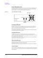
“Required Tools”
•
“Kelvin Cable Output Signal”
•
“Start-Up”
Required Tools
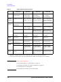
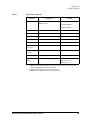
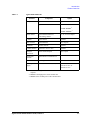
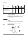
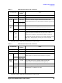
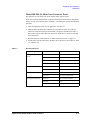
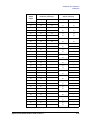
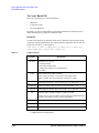
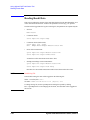
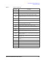
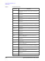
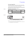
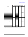
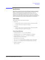
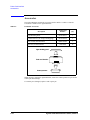
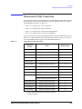
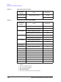
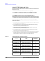
Before starting the verification, prepare the tools listed in Table 3-1. The tools except for
the multimeter are furnished with the Agilent 41000.
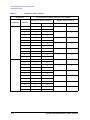
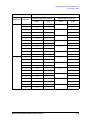
Table 3-1
Required Tools
Agilent model number / part number / description
Purpose
Qty.
E2373A basic 3.5 digit handheld multimeter or equivalent
connection check
1
E3140A test fixture adapter
for all
1
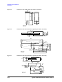
E3142A performance check fixture for low current
noise offset and
settling time/
leakage current
measurements
1
connection check
1
E3190-60042 PV open fixture 1
E3144-60001 card fixture (used to fix probe card) 2
E3143A connection check fixture set for PCIF
E3141A (E3141-60005) universal test fixture
for manual mode
E3143-60001 connection check fixture
for batch mode
1250-2618 triaxial female to female through adapter
1250-1708 triaxial open connector
for
troubleshooting
1
1
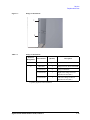
1. To perform the measurements at the tip of the B2220A pins, use E3190-60042.
2. To perform the measurements at the tip of the probe card, use E3144-60001.
NOTE
For the Agilent 41000 Model 100/200, ignore the Agilent E3140A/E3142A/E3143A. They
are required only for the Model 300/400.
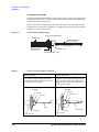
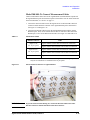
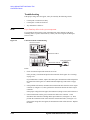
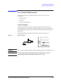
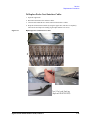
Kelvin Cable Output Signal
Even if a Kelvin input is configured to the switch mainframe input, the all switch module
outputs must configure the Kelvin output. Then the Kelvin cable must be used to connect
between the switch module and the probe card interface. Do not use the triaxial cable.
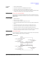
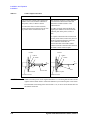
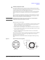
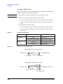
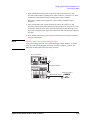
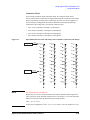
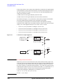
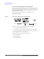
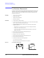
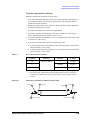
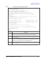
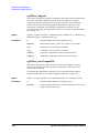
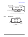
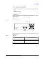
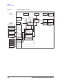
In this connection, the verification tool controls the switches as shown below.
•
to apply the force/sense signals to each line of the Kelvin output properly.
•
to apply the non-Kelvin signal to both lines of the Kelvin output.
Agilent 41000 Administration Guide, Edition 3
3- 7