1
CHAPTER 3: CONNECTING TO THE NETWORK
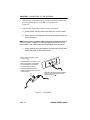
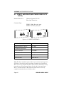
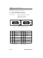
Position X
(crossed over)
1. RX+
2. RX3. TX+
4. NC
5. NC
6. TX7. NC
8. NC
Position =
(not crossed over)
1. TX+
2. TX3. RX+
4. NC
5. NC
6. RX7. NC
8. NC
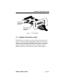
Figure 3-1. EPIM-T Cross-over Switch
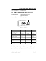
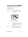
To connect an EPIM-T to a Twisted Pair Segment:
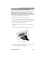
1. Insert the RJ45 connector on the twisted pair segment into the RJ45
port on the EPIM. See Figure 3-1.
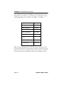
2. Check that the EPIM’s LNK LED is on. If the LED is not on, perform
each of the following steps until it is:
a. Check that the 10BASE-T device at the other end of the twisted
pair segment is powered up.
b. Verify that the RJ45 connector on the twisted pair segment has
the proper pinouts.
c.
Check the cable for continuity.
d. Check that the twisted pair connection meets dB loss and cable
specifications outlined in Appendix B.
e.
Check that the crossover switch is in the correct position.
If a link still has not been established, contact Cabletron Systems
Technical Support.
Page 14
BRIM-E6 USER’S GUIDE