1
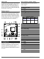
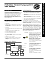
Initial inspection
Introduction
Your shipping box should contain the following items:
The PCM-3521 Flat-panel/CRT VGA Module
supports a wide range of popular LCD, EL and gas
plasma flat-panel displays and traditional analog
CRT monitors in high resolution display modes,
while maintaining complete register, gate and
BIOS compatibility with IBM VGA displays. A flatpanel display and a CRT VGA display can be
used simultaneously.
• One PCM-3521 Flat-panel/CRT Display Module
• CD-ROM or disks for utility, drivers, and manual (in
PDF format)
• One bracket with 15-pin connector for VGA CRT
(part no. 1701150151)
• One PC/104 support package (part no. 9686104002)
• One PCM-3521 Startup Manual
Specifications
Your PCM-3521 was carefully inspected both
mechanically and electrically before being shipped. It
should be free of marks and scratches and should be
in perfect working order.
• Standard 16-bit PC/104 form factor
• C&T 65545
When unpacking, check the unit for any signs of
damage (scratches, dents, torn shipping box, etc.). If
there is any damage to the unit or if it fails to meet the
specifications, please notify our service department or
your local sales representative immediately. In addition,
you should contact the carrier and refain the shipping
carton and packing material for inspection by the
carrier. Advantech will then make arrangements to
either repair or replace the unit.
• Supports CRT and flat-panel (EL, LCD, and gas
plasma) displays. Simultaneous usage of CRT
and flat panel.
• Resolution:
Non-interlaced CRT monitor: up to 800 x 600 @
256 colors
Flat panel: up to 800 x 600 @ 256 colors
• On-board 1MB display memory
• On-board 512 KB frame buffer
WARNING!
Discharge your body’s static electric
charge by touching the back of the
grounded chassis of the system unit
(metal) before handling the board.
You should avoid contact with
materials that hold a static charge
such as plastic, vinyl, and
styrofoam. The board should be
handled only by its edges to avoid
static damage to its integrated
circuits. Avoid touching the exposed
circuit connectors.
NOTE:
1. For more detailed information on
the PCM-3521, please refer to the
full manual contained in the
accompanying CD-ROM or disk (in
PDF format).
• DC to DC converter supplies LCD bias voltage
(VEE -35 V ~ +35 V)
• Supports 3.3 V / 5 V LCDs
• On-board variable resistor for panel contrast
adjustment (may be extended by wires to
display)
System block diagram
PCM-3521 PC/104 Flat-panel/CRT VGA Module
PCM-3521 PC/104 Flat-panel/CRT
VGA Module
PCM-3521
PCA-6653 System block diagram
Address
BIOS
Data
24
RGB
H/V Sync
Address
16
Data
65540/45
Panel Data
To CRT Display
24
To Flat Panel Display
Panel Control
Power-on
Control
/ENVEE
32
16-bit
ISA BUS
1MB Video
Memory
PCM-3521 User's Manual
16
512KB
Frame Buffer
+VEE
Sequencing
+V
-VEE
-V
2. Acrobat Reader is acquired to
view any PDF files. Acrobat Reader
can be downloaded at
www.adobe.com/Prodindex/acrobat/
readstep.html
(Acrobat is a trademark of Adobe)
DC-DC
Converter
PC/104 and the PC/104 logo are trademarks of the PC/104 Consortium
1
Part no. 2006352101 2nd Edition Printed in Taiwan July 1999
Video BIOS
Quick reference jumper setting
The PCM-3521's hardware supports a wide variety of
flat-panel and analog CRT displays. However, special
software routines and parameters are needed to
interface with any given display. These routines are
stored on the PCM-3521 in a 64 KB ROM BIOS chip.
The high performance CHIPS 65545 VGA, BIOS used
within this unit is optimized for usage with 65545 VGA
Flat-panel/CRT controller chips.
For safe installing, refer to the user's manual for
detailed information.
Display support
The 65545 VGA BIOS supports monochrome LCD, EL,
plasme, color TFT and STN LCD flat-panel displays. It
is fully compatible with IBM VGA displays - even with
interlaced and non-interlaced analog monitors (VGA
color and VGA monochrome) in high-resolution mode.
Multiple frequency (multisync) monitors ar esupported
as analog monitors. Both CRT and panel displays can
be used simultaneously. However, digital monitors,
such as MDA, CGA, EGA are not supported.
Jumper settings
J1: Panel Power setting
Pins
1-2
Signal
+5 V
2-3
+3.3 V
J2: Power V EE setting
Pins
1-2
Signal
+5 V ~ +35 V
2-3
-5 V ~ -35 V
VR1, VR2: Power V EE adjustment
Function
VR1 (pin 1)
for internal
adjustment of the
LCD V EE
for external
adjustment of the
LCD V EE - an
additonal VR is
required
connects to the
external VR
VR1 (pin 2, 3)
VR2
Short (default)
1 ~ 50 K ohm
connects to the
external VR
0 ohm
J3: ENABKL setting
Pins
1-2
Signal
ENABKL
2-3
-ENABKL
J6 & J7: BIOS setting
S i g n a l J7
BANK0 S
J6
S
LCD
24TFT
BANK1 O
S
EL
BANK2 S
O
MONO
BANK3 O
O
STN
J8: Contrast setting
Pins
1-2:
Signal
+V EE or -V EE
2-3:
0 V ~ +3.3 V
J9: SHFCLK setting
Configuration
Although the PCM-3521 is compatibile with many types
of displays, its configuration is quite simple, since
most of the configurations are done in the BIOS setup.
The section describes the hardware settings
necessary to get your display operational. Furthermore,
some of the PCM-3521's special features are given in
this section.
2
Pins
1-2:
Signal
SHFCLK
2-3:
-SHFCLK
J10: LCD control
Pins
1:
Signal
+12 V
2:
GND
3:
ENBKL
4:
0 V ~ +5 V
5:
+5 V
PCM-3521 User's Manual
Connectors
CN1
PC/104 connector
The purpose of the enclosed software drivers is to
take advantage of the extended features of the CHIPS
VGA flat-panel/CRT controller. Its capabilities include:
CN2
LCD connector
•
High performance in Microsoft Windows
JP1
CRT connector
•
Resolutions up to 800 x 600 in graphics
mode with 256 colors
•
Resolutions up to 640 x 480 in graphics
mode with 256 colors
•
132 column text mode
Adjustments
R28
+3.3 V contrast VR connect
R30
brightness VR connect
VR1
+/-VEE contrast VR connect
Installation
After all of the jumpers have been set, you can install
the PCM-3521 on your CPU card. If this is the first time
you are installing a CPU card, you should check its
jumpers before installing the PCM-3521, as they may
later be inaccessible. Next, carefully slide the pins of
the PCM-3521 into the PC/104 connector on the card.
Secure the PCM-3521 onto the card with the screw
provided.
Adjusting the VEE output
It could happen that the VEE output needs to be
adjusted to suit the Advantech LCD panel. In this
case, just power up the system and connect a
voltmeter to pin 1 (LCD VEE) and pin 39/40 (GND) of
P2. Use a screwdriver to adjust the variable rsistor
VR1 until you reach the proper VEE output for your
display.
Connectors
Attach the panel cable to the correct connector on the
PCM-3521, then connect the other end of the cable to
your display. Install the CPU card according to the
instructions given in the CPU manual. Consequently,
power up your system. Should any problems arise,
please refer to the section 'Troubleshooting'.
Display Drivers and Utilities
The Windows drivers included in this package have
several special features:
•
Pen Windows Extensions
•
Panning Drivers
•
Linear Acceleration Drivers
Hardware configuration
Some of the high-resolution drivers provided in this
package will work only in certain system configurations. If a driver does not display correctly, try the
following:
1. Change the display controller to the CRT-only
mode, rather than the flat panel or the simultaneous mode. Some high-resolution drivers wil
display properly only in the CRT mode.
2. If a high-resolution mode is not supported on your
system, try using a lower-resolution mode. For
example, if the 1024 x 768 mode will not work,
choose the 800 x 600 mode.
3. The 65510 flat-panel VGA controller supports only
those drivers that display 640 x 480 panels. Refer
to the following section on driver resolutions and
filenames for a list of the drivers that can be used
on the 65510.
4. The 65545 and 65540 flat-panel VGA controllers
support additional drivers that function with the
F65535 and F65540 only. See the following section
on driver resolutions and filenames for a list of
these drivers.
The Display Driver diskettes provided with your VGA
adapter contain all the necessary software for
installation and operation of your drivers.
The VGA adapter is based on the CHIPS VGA flatpanel/CRT controller and is fully IBM VGA compatible.
This controller offers a large set of extended functions
and high resolutions. If you intend to use the VGA
adapter in the VGA mode only, you de not need to
install any of these drivers. Since the VGA adapter is
fully compatible, it does not require any special drivers
to operate in the standard mode.
PCM-3521 User's Manual
3
These software drivers support the following software
applications in the filenames and resolutions listed:
Driver Resolution & Filenames
Application Filename
Windows 3.1 LINEAR4.DRV
LINEAR8.DRV
Resolution
640x480
Colors Notes
16
510
800x600
16
640x480
256
800x600
256
510
1024x768
256
545/540
LINEAR15.DRV
640x480
32K
545/540
LINEAR16.DRV
640x480
64K
545/540
LINEAR24.DRV
640x480
16M
540
W3LM600P.DRV 800x600
16
W3LM768P.DRV 1024x768
16
W3PM480.DRV
640x480
256
W3PM600P.DRV 800x600
256
R12.DRV
480x640
16
OS/2 Version SV480256.DLL
640x480
256
2.1
800x600
256
PD600256.DLL
510
510
PD768256.DLL1 0 2 4 x 7 6 8 2 5 6
AutoCAD
DLDVGA.EXE
640x480
16
800x600
16
510
256
510
Lotus 1-2-3 V132X25.DRV 132x25(text)16
V132X50.DRV 132x50(text)16
Word 5.0
Word 5.5
VGA600.VID
800x600
VGA768.VID
1024x768 16
VGA55600.VID 8 0 0 x 6 0 0
3. Change to the directory where you installed
Windows (usually C:\WINDOWS).
4. Type SETUP <ENTER> to run the Windows setup
program, which will show the current Windows
configurations. Use the up arrow key to move to
the Display line and press <ENTER>. A list of
display drivers will be shown. Then use the arrow
keys to select one of the drivers starting with an
asterix (*) and press <ENTER>.
5. Follow the directions on the screen to complete the
setup. In most cases, you may press <ENTER> to
accept the suggested option. When the setup is
done, it will automatically return to DOS. Type WIN
<ENTER> to start Windows with the new display
driver.
Changing display drivers from DOS
1024x768 16
640x480
2. Place the Display Driver Diskette # 1 in driver A.
Type A: <ENTER> to make this the default drive.
Type SETUP <ENTER> to run the driver setup
prgram. Press any key to get to the applications
list. Using the arrow keys, select Windows version
3.1 and press the <ENTER> key. Use the <ENTER>
key to select All Resolutions, then press <END> to
begin the installation procedure. At this point, you
will be asked for the path to your Windows system
directory (default C:\WINDOWS). When the
installation is complete, press any key to continue.
Press <ESC> followed by Y to exit to DOS.
16
16
To change display drivers from DOS, change to the
Windows directory and run Setup, repeating steps 4
and 5 from the previous section. Besides the special
display drivers marked by an asteriks (*), you should
be able to use the following standard drivers:
VGA: 640 x 480, 16 colors
Super VGA: 800 x 600, 16 colors
VGA55768.VID 1 0 2 4 x 7 6 8 1 6
WordperfectCHIPS600.WPD8 0 0 x 6 0 0
5.0
16
CHIPS768.WPD1 0 2 4 x 7 6 8 1 6
WordperfectVGA600.VRS
800x600
5.1
1024x768 16
VGA768.VRS
Notes:
16
510 - can be used on the 65510
controller.
545/540 - operates with the 65545
and 65540 controllers only.
540 - functions with the 65540
controller only.
Windows
These drivers are designed to work under Microsoft
Windows version 3.1 and Pen Windows version 3.1..
Driver installation
1. Install Windows as you normally would for a VGA
display. Run WIndows to make sure that it is
working correctly. Then exit from Windows.
4
Changing display drivers from Windows
Select the Windows Setup icon from the main window,
which will then show the current setup configuration.
Select change system settings from the option menu.
Click on the arrow at the end of the display line to
access the list of display drivers. Select the driver
preferred, then click on the OK button. Follow the
directions to complete the setup procedure.
Changing color schemes
After you change display drivers, you may notice that
the color scheme used by Windows looks strange as
different drivers have different default colors. In order
to change the color schemes, open the control panel
within the main window and select the color icon.
Choose the color scheme preferred and click on the
OK button.
Panning drivers
Special panning drivers are provided to allow highresolution modes to be displayed on a flat panel or
CRT. these drivers will show a section of a larger, and
will automatically pan or scroll the screen horizontally
and vertically when the mouse pointer reaches the
edge of the display.
PCM-3521 User's Manual
Linear acceleration drivers
A special high-performance linear acceleration driver is
provided for the 256-color mode. This driver may
require special hardware and may not be supported on
all systems. This driver is only available for Windows
3.1. One feature quoted is QuickTime-Aware.
OS/2
These drivers are designed to function with the OS/2
2.1 operating system.
Driver installation
Note:
Always sue the INSTALL, CMD for
the FIRST installation of the video
device drivers. To change video
resolutions, use the DSPINSTL
program.
1. Install the OS/2 the same way you would a VGA
display. Open an OS/2 full screen or window
session.
2. Place the Display Driver Diskette # 3 in drive A.
Type A: <ENTER> to make this the default drive.
The type INSTALL A: C: <ENTER>. Once the
drivers are installed, the DSPINSTL program is
automatically invoked. Follow the progam's
instructions to set up the OS/2 drivers in your
system. Once the installation is complete, the
system must be shut down and restarted for the
changes to take effect.
Driver diskette copy
Note:
Diskette copies of the OS/2 drivers
must have a VOLUME LABEL that
reads "DISP 1" in order to be an
installable diskette.
To copy the OS/2 Display Driver Diskette # 3, follow
these instructions:
1. Copy all files from the Display Driver Diskette # 3
to any other diskette.
2. Place the diskette in drive A. At the C:\prompt,
type LABEL A: DISK 1 to properly label your
diskette. Then store your diskette copy in a safe
place. For proper installation of OS/2 drivers, all
diskette copies must be properly labeled "DISK 1".
the <ENTER> key to select All resolutions, then
press <END> to begin the actual installation. At this
point, you will be asked for a drive and directory to
copy the driver files to. Enter the drive and
directory, which contains the installed AutoCAD. You
might be asked to change the display driver
diskettes, and if the destination directory does not
exist, you will be asked for confirmation. When the
installation is complete, press any key to continue.
Then press <ESC> followed by Y to exit to DOS.
2. Go to the AutoCAD directory where the new drivers
were installed and run the driver installation
program by typing DLDSETUP <ENTER>. This
program will configure your new and fast display,
and will create a batch file under the name
FASTACAD.BAT.
3. Configure the colors for AutoCAD by using one of
the following settings: COLOR16 <ENTER>, if a 16color mode is used, or type COLOR256 <ENTER> if
a 256-color mode is used. Start by pressing A to
select the standard AutoCAD ADI colors. Press S
to save these color settings in DLDCOLOR.DAT. For
further information about these color utilities see
Changing Colors later in this section.
4. Prior to starting an AutoCAD or AutoShade session,
the display driver must be installed in the computer
memory. To do so, execute the batch file created
by typing FASTACAD <ENTER>. To remove the
display driver from memory when finished useing
AutoCAD, you can typ DLDVGA-U <ENTER>.
Configuring AutoCAD
The firs time you use AutoCAD with ADI driver, you
need to configure the AutoCAD application for an ADI
display. Select CONFIGURE AUTOCAD from the
AutoCAD main menu. The select CONFIGURE VIDEO
DISPLAY. Select ADI display as your new driver
(installed at interrupt 7A hex). Save the new
configuration and return to the main menu.
Configuring AutoShade
Before using AutoShade with an ADI driver, you should
configure your AutoShade application in the proper
settings. Before running AutoShade, remove the file
SHADE.CFG (use DOS DELETE command if needed).
Then run AutoShade. The program will ask for a display
and rendering driver. Select ADI for both drivers and
indicate that you have a dual display system. When
you exit the AutoShade program, a new SHADE.CFG
will be created.
AutoCAD
Changing colors
These drivers are designed to work with Autodesk
AutoCAD and AutoCAD/386 Release 10 and 11, and
corresponding versions of AutoShade. They all conform
to the Autodesk Device Interface (ADI) for rendering
devices and display drivers. These drivers accelerate
redraw, pan, and zoom functions.
To change the colors that AutoCAd uses fro drawings,
backgrounds, menus, and text fro˚˚ormats, use the
utility COLOR16 (for a 16-color mode) or COLOR256
(for a 256-color mode). When running these utilities,
use the ? key at any time to access context-sensitive
help messages, which will explain how to use the
program.
Driver installation
For example, when you want to change AutoCAD's
background color to the 16-color mode, run the utility
COLOR16. Press O for object. Use the left and right
arrow keys to move through the different objects
(shown at the top of the screen) unitl Graphics Area
Background appears. Press <ENTER> to select this
object.. The current color will be shown at the bottom
of the screen. Use the left and right arrow keys to
move to a new color and press <ENTER> to select.
1. Place the Display Driver Diskette # 1 in drive A.
Type A: <ENTER> to make this the default drive.
Type SETUP <ENTER> to run the setup program.
Press any key to get to the applications list. Using
the arrow key, select AutoCAD and AutoCAD/386
Release 10 & 11 and press <\ENTER>. This will
display a list of supported driver resolutions. Press
PCM-3521 User's Manual
5
When you are done changing objects, press <ESC> to
exit to the main menu. Press S to save these colors in
the file DLDCOLOR.DAT. Then press E to exit.
you start Lotus 1-2-3. In other words, if you named
your driver set 132X25.SET, give the following
command to start Lotus 1-2-3:
123 123X25.SET <ENTER>
Lotus 1-2-3 Lotus Symphony
These drivers are designated for applications such as
Lotus 1-2-3 version 2.0, 2.01 and 2.2, and with Lotus
Symphony version 1.0 and 1.1.
Driver installation
1. Place Display Driver Diskette # 1 into drive A and
make this the default drive by typing A: <ENTER>.
Then run the setup program by by typing SETUP
<ENTER>. Press any key to display a list of the
applications supported. Use the arrow keys to
select Lotus/Symphony and press <ENTER>. A list
of supported screen resolutions will be displayed.
Agian, use the arrow keys to select the desired
screen resolution and press <ENTER> (make sure
that your monitor is able to to display the resolution
you have just selected). In order to begin the
installation procedure, press <END>. A default drive
and directory will be displayed, simply use the
backspace key to erase the current default, and
then type in the 123 directory. You might be
prompted to insert one of the other driver diskettes.
You also might be asked to create the target
directory if it does not already exist. After the files
have been installed, press any key to return to the
list of supported applications. Press <ESC>
followed by Y to exit to DOS. Copy all the files
which were just created in the temporary directory
onto a formatted floppy diskette.
2. Go to the 123 directory and start the installation
program. Type the following commands:
WordPerfect
These drivers are for WordPerfect version 5.0 and 5.1.
They further support 132-column display in editing
mode and high-resolution graphics in preview mode.
Driver installation
1. Place Display Driver Diskette # 1 into drive A and
make it the default driver by typing A: <ENTER>.
Press any key to display a list of supported
applications. Use the arrow keys to select
WordPerfect and press <ENTER>. A list of screen
resolutions will appear, you can use the arrow keys
to select the preferred resolution and press
<ENTER> (make sure that your monitor is able to
display this resolution). Then press <END> to
commence the installation procedure. A default
drive and directory path will be displayed. Erase
this default setting with the backspace key and
type in the WordPerfect directory. You might be
prompted to insert one of the other driver diskettes.
In addition, you might be asked to create the target
directory if it does not already exist. After the files
have been installed, press any key to return to list
of supported applications. Press <ESC> followed by
Y to exit to DOS.
2. Start WordPerfect and press <SHIFT> + <F1> to
enter the setup menu. Select D for DISPLAY and G
for GRAPHICS SCREEN TYPE and then choose the
desired Chips VGA resolution.
C: <ENTER> INSTALL <ENTER>
Configuring WordPerfect 5.0 for 132 columns
3. The Lotus installation program will load and present
the installation menu. From this menu, choose
ADVANCED OPTIONS. Then, from the advanced
options menu, select ADD NEW DRIVERS TO
LIBRARY. This will open up en new menu from
which you select MODIFY CURRENT DRIVER SET.
Then choose TEXT DISPLAY and opt for one of the
drivers.
1. Use the SETCOL program to set 132 columns and
25 rows. Then type
4. After the selection of the appropriate VGA display
driver, you will need to exit this menu and return to
the main Lotus installation menu. Do this by
selecting RETURN TO MENU.
5. In the main menu, choose SAVE CHANGES.
6. The installation program will prompt you for the
name of your new Lotus configuration file. Lotus will
display the default value - 123.SET. However, you
do not have to use this name. You may want to use
a filename that indicates the resolution of the driver
it contains.For instance, if you have installed a 132
column by 25 line driver, we suggest you name it
132X25.SET. Likewise, a 80 by 50 driver can be
saved as 80X50.SET.
7. The installation of your Lotus 1-2-3 driver is now
complete. At the main Lotus installation menu,
select EXIT.
SETCOL 132, 25 <ENTER>
2. Start WordPerfect. The program will detect the
number of rows and columns automatically. If for
some reason WordPerfect is unable to adapt to 132
columns by 25 rows, strat WordPerfect by typing:
WP / SS=25,132 <ENTER>
Configuring WordPerfect 5.1 for 132 columns
Start WordPerfect and press <SHIFT> + <F1> to enter
the setup menu. Select D for DISPLAY and T for TEXT
SCREEN TYPE. Then select Chips 132 Columns Text.
Display Drivers and Utilities
This section describes the operation and installation of
the following software utilities supplied on the Display
Driver Diskettes: CHIPSCPL and SETCOL.
The CHIPSCPL utility program
This utility program works on a Microsoft Windows
version 3.1 platform.
If you use a name for the driver set that is different
from 123.SET, you have to remember to place the
filename of your driver set on the command line when
6
PCM-3521 User's Manual
Installing the utility
applications. Use the arrow key to select Utilities
and press <ENTER>. A list of utilities will be
displayed, so use the arrow keys to choose the
preferred utility and press <ENTER>. Proceed with
pressing <END>, which will start the installation of
the utility. When a default drive and directory path
are displayed, use the backspace key to erase the
defaults and type in the proper directory. You might
be prompted to insert one of the other diskettes.
Furthermore, you might be asked to create a
directory if it did not already exist. After all files
have been installed, press any key to return to the
list of applications, then press <ESC> follwed by Y
to exit to DOS.
The CPL within CHIPSCPL is a Windows-based utility
to select resolutions and color depth. It is a Control
Panel Applet with its own icon that is automatically
installed when setting up the CHIPS Windows 3.1 linear
drivers. The control panel icon is in the main windows
group. To invoke the control panel applet, simply click
on the icon. The driver resolution and color depth take
effect only after Windows is rebooted with the new
driver.
Operating the utility
SIZE <ALT> + <S>
allows you to select from the following resolutions:
640 x 480 800 x 600 1024 x 768 1280 x 1024
By selecting the resolution first, it will determine the
allowable selections for color depth.
COLOR <ALT> + <O>
permits you to select the number of colors from the
following:
16 (4 bits per pixel)
64 K (16 bpp)
256 (8 bpp) 32 K (15 bpp)
16 M (24 bpp)
Selecting the color depth first, will determine the
options for resolutions.
Operating the utility
The SETCOL utility program enables you to specify the
number of rows and columns on screen. You can set
values to the SETCOL program by placing them after
the name SETCOL on the command line. The proper
format for the command is:
SETCOL COLUMNS, ROWS <ENTER>
Valid values for columns and rows are:
COLUMNS ROWS 80 or 132 25 or 50
If you want to set set 132 columns with 25 rows, give
the following command:
DISPLAY TYPE <ALT> + <D>
SETCOL 132, 25 <ENTER>
will give you the ability to choose a display type:
CRT only
<ALT> + <C>
LCD (flat panel) only
<ALT> + <L>
Both CRT and flat panel
<ALT> + <B>
POWER SAVER <ALT> + <P>
with this function, you can save power by turning off
either the back light or the panel after a certain period
of inactivity. This feature is available for the 65535 and
65540 only.
If you intend to use this utility with applications such
as WordStar or WordPerfect, you should first check if
these programs are properly configured for the specific
screen size. Please refer to the other sections in this
manual on how to configure your applications.
Please bear in mind that certain monitors cannot
display 50 character rows on screen, due to hardware
limitations. The following table specifies how many rows
can be displayed on common monitors:
FONT <ALT> + <F>
will allow you to choose between larger or smaller
fonts.
VERSION <ALT> + <V>
displays version information regarding the current
driver.
BIG CURSOR <ALT> + <G>
enables you to select a big cursor for better visibility
on the flat panel.
The SETCOL utility program
This utility program is used to provide 132 text
columns in popular text-based applications such as
WordPerfect. If you do not intend to use the 132
columns text mode, we advise you not to install this
utility.
Installing the utility
1. Determine where you wnat to store the program.
Locate a directory on your hard disk where you
havee other utility programs. For your convenience,
this directory should be specified in the
PATH=statement in your AUTOEXEC.BAT file.
2. Place Display Driver Diskette # 1 into drive A and
make it the default driver by typing A: <ENTER>.
Run the setup program by typing SETUP <ENTER>.
Press any key to display the list of supported
PCM-3521 User's Manual
Monitor
Rows
IBM Monochrome
25
IBM Color Graphics
Display
25
IBM Enhanced Graphics
Display
25
IBM VGA Display (analog)
25 or 50
Mutli-frequency Display
25 or 50
Troubleshooting
If you experience a problem after installing the PCM3521, check the following:
• Make sure all electrical cords and cables are
properly connected, and that all plugs are firmly
seated in their sockets.
•
See to it that the display itself is properly
connected, and that its power is switched on.
•
Check if the module is correctly attached to your
CPU card.
•
Be sure that the CPU card is operating correctly.
7
•
See if no other devices, such as a Flash/RAM/ROM
disk, CPU card, or DA&C card occupy the same I/
O address as the PCM-3521. If this is the case,
consult the device's manual to set it to an
alternative address. The PCM-3521 uses I/O
addresses from 3BCH, 3BDH and 3BEH which are
reserved by the system for its parallel ports.
If the problem persists, please refer to your flat-panel
display manual
A27
A04
B27
---
A28
A03
B28
ALE
A29
A02
B29
+5 V
A30
A01
B30
---
A31
A00
B31
GND
A32
GND
B32
GND
PC/104 Connector pins C & D
Pin
C01
Boot test audible signals
The 65545 BIOS runs tests on the display system
during boot up. If an error occurs, you will be notified
by one long beep, followed by a number of short
beeps. See table below:
Audible signals
Beep Pattern
1 long, 2 short
Error Condition
Horizontal retrace failed
Signal
GND
Pin
D01
Signal
GDN
C02
-SBHE
D02
-MEMCS16
C03
LA23
D03
-IOCS16
C04
LA22
D04
---
C05
LA21
D05
---
C06
LA20
D06
---
C07
LA19
D07
---
C08
LA18
D08
---
1 long, 3 short
DAC test failed
C09
LA17
D09
---
1 long, 4 short
Monitor sense failed
C10
-MEMR
D10
---
1 long, 5 short
Vertical retrace failed
C11
-MEMW
D11
---
1 long, 6 short
Video memory test failed
C12
SD08
D12
---
C13
SD09
D13
---
C14
SD10
D14
---
C15
SD11
D15
---
C16
SD12
D16
---
C17
SD13
D17
+5 V
C18
SD14
D18
---
C19
SD15
D19
GND
C20
GND
D20
GND
Connector pin assignments
PC/104 Connector pins A & B
Pin
A01
Signal
---
Pin
B01
Signal
GND
A02
SD7
B02
RESDRV
A03
SD6
B03
+5 V
A04
SD5
B04
IRQ9
A05
SD4
B05
---
A06
SD3
B06
---
A07
SD2
B07
---
A08
SD1
B08
-0WS
A09
SD0
B09
+12 V
A10
RDY
B10
GND
A11
AEN
B11
---
A12
---
B12
---
A13
---
B13
-IOW
A14
---
B14
-IOR
A15
A16
B15
---
A16
A15
B16
---
A17
A14
B17
---
A18
A13
B18
---
A19
A12
B19
-REFSH
A20
A11
B20
---
A21
A10
B21
---
A22
A09
B22
---
A23
A08
B23
---
A24
A07
B24
---
A25
A06
B25
---
A26
A05
B26
---
8
JP1: Analog CRT VGA monitor pin assignments
pin
1
function
R
pin
2
function
---
3
G
4
GND
5
B
6
---
7
---
8
---
9
GND
10
HSC
11
GND
12
VSC
13
GND
14
---
15
GND
16
---
PCM-3521 User's Manual
CN2: LCD flat-panel connector assignment
Interface with 2 standard LCDs
pin
1
signal
+12 V
pin
2
signal
+12 V
3
GND
4
GND
5
+5 V
6
+5 V
PCM-3521
P2 connector Toshiba
7
VEE
8
GND
Pin
Function
Pin
Function
9
P00
10
P01
2
P7 (G2)
CN1-9
G0
11
P02
12
P03
8
P4 (B4)
CN2-5
B2
13
P04
14
P05
10
P3 (B3)
CN2-3
B1
15
P06
16
P07
12
P2 (B2)
CN2-1
B0
17
P08
18
P09
15
ASHFCLK
CN1-1
NCLK
19
P10
20
P11
20
P14 (R14)
CN1-7
R2
21
P12
22
P13
21
P9 (G4)
CN1-13
G2
23
P14
24
P15
22
P13 (R3)
CN1-5
R1
25
P16
26
P17
23
P8 (G3)
CN1-11
G1
27
P18
28
P19
24
P12 (R2)
CN1-3
R0
29
P20
30
P21
29
BLANK# (DE)
CN2-7
ENAB
31
P22
32
P23
33
VCC
CN2-9
V CC
33
GND
34
GND
34
VCC
CN2-10
V CC
35
SHFCLK
36
FLM
30 ~ 40
GROUND
CN1-2 / 1-4
GND
37
M/DE
38
LP
CN1-10/ 1-12
39
GND
40
ENABKL
CN1-14 / 2-2
41
NC
42
NC
CN2-4 / 2-6
43
CONTRAST VR1
44
CONTRAST VR2
CN2-8
PCM-3521 connection to Toshiba LTM-09C015-1
(640 x 480 512 color TFT LCD panel)
panel connector
PCM-3521 connection to Sharp LM64P83
(640 x 480 monochrome LCD DD panel)
PCM-3521
PCM-3521 User's Manual
Sharp
Pin
Function
Pin
Function
1
VEE
7
VEE
2
P7
12
DL0
3/7
VDD
5/4
VDD/DISP
4
P6
13
DL1
6
P5
14
DL2
8
P4
15
DL3
10
P3
8
DU0
11
FLM (VS)
---
S1
12
P2
9
DU1
13
LP (HS)
2
CP1
14
P1
10
DU2
15
ASHFCLK
3
CP2
16
P0
11
DU3
31/32
+12 V
---
---
39/40
GROUND
6
VSS
9