1
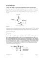
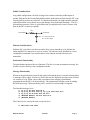
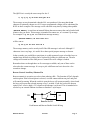
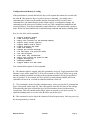
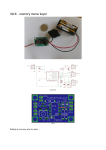
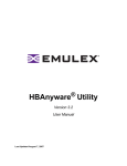
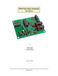
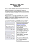
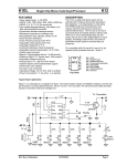
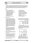
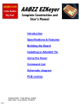
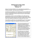
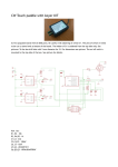
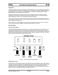
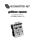
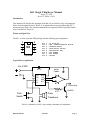
K8+ Single Chip Keyer Manual August 13, 1998 Steven T. Elliott - K1EL Introduction This manual will describe the operation of the K8+ Keyer which is a low cost automatic Morse keyer designed by Steve, K1EL. It is implemented in an 8 pin Microchip PIC microprocessor. Only a few external components are required to build a powerful iambic keyer with the K8+ Keyer I.C. Pinout and Signal List The K8+ is in an 8 pin mini DIP package with the following pin assignments: 1 2 3 4 8 7 6 5 K8 Pin Pin Pin Pin Pin Pin Pin Pin Top View 1 2 3 4 5 6 7 8 : : : : : : : : +5 Volts DC Aux. Sidetone/Beacon Switch Sidetone Audio Push Button Switch Transmitter Key Dah Paddle Dit Paddle Ground Typical Keyer Application 3 to 5 VDC .01 uF 1 2 3 4 VCC STK ST PB Iambic Paddle GND DIT DAH KEY 8 7 6 5 To Xmtr Key 4.7K Push Switch 2N2222 Piezo Transducer Here is a schematic of a K8+ keyer using a minimum of components K8 Plus Manual 03/23/99 Page 1 Keying Considerations The PIC is not capable of directly keying a transmitter and requires a transistor buffer between the keyer chip and the transmitter. The schematic above would be used for positive keying. The diagram below would be substituted for negative keying. Most modern rigs utilize positive keying while older tube style rigs generally are negative keyed. The manual for your transmitter or transceiver will specify whether the keying voltage is positive or negative. +3 to 5 VDC 100 1K From PIC Pin 5 2N3904 120 2N3906 To Xmtr Keying Input -30 VDC 20 ma MAX Negative Keying Scheme Caution ! The negative keying circuit shown has a max. rating of -30 volts at 20 mA. In some cases the transmitter may exceed this rating and will require a more robust circuit. Contact K1EL for alternate keying schemes. Construction The K8+ keyer can be constructed on a small piece of perf-board. The layout is not critical, be sure to include the .01 µF capacitor and place it as close as possible to pins 1 and 8 on the PIC. If using a supply greater than 5 volts, use a 78L05 regulator to provide 5 volts for the K8+. It is recommended to use a socket for the K8+ to avoid overheating it while soldering. Be sure to use a normally open switch for the push-button. All parts shown can be purchased at a local Radio Shack store. The RS 273-073 piezo element works well as a sidetone output speaker. If installing the K8+ directly in your transceiver, the sidetone audio should be fed into the receiver's audio chain, it may be necessary to reduce the output level by using an attenuator network such as shown below: C1 Out In R1 R2 K8 Plus Manual Choose R1 & R2 for desired attentuation C2 Choose C1 & C2 for desired wave shaping: .001 to .01uF typical 03/23/99 Page 2 Paddle Considerations Any paddle configuration will work as long as the contacts switch the paddle inputs to ground. Pull-ups for the Dit and Dah paddles and the push-button are built into the PIC so no external pull-up resistors are required. In a harsh environment you might consider using the optional protection circuit shown to prevent damage from electrostatic discharge. This is a precautionary measure if there is a possibility that you might directly come in contact with pins on the PIC via the keyer paddle. R1 From Paddle To K8 Input C1 C1= 100 pF to .001 uF R1 = 33 to 47 ohms Sidetone Considerations Sidetone Pin 3 provides a tone that can either drive a piezo transducer or be fed into the audio amplifier of a transceiver's receiver section. The sidetone can be disabled by a keyer configuration command if you would rather use the sidetone already built into your transmitter. Push-button Functionality The push-button input provides two functions. The first is to start an automatic message, the second is to place the keyer into configuration mode. Message Functionality Whenever the push-button is pressed and quickly released the keyer's currently selected builtin message will be output. You have a choice between five different messages most of which are varieties of CQs. When a keyer chip is purchased your callsign is permanently programmed into the PIC's on board memory. The programmed callsign is used in sending the built-in message. When purchasing a K8+ you have several message list options: The Standard message list is: 1) 2) 3) 4) 5) CQ CQ CQ CQ CQ CQ CQ CQ CQ (MESSAGE (MESSAGE DE K1EL K1EL AR DE K1EL K1EL CQ DX DE K1EL K1EL MEMORY) DE K1EL MEMORY) K CQ CQ DE K1EL K1EL AR K DX AR K K1EL AR K The Contest List is exactly the same except for slot 2: 2) TEST K1EL K1EL TEST K8 Plus Manual 03/23/99 Page 3 The QRP List is exactly the same except for slot 2: 2) CQ CQ CQ CQ DE K1EL K1EL/QRP AR K The message set was determined when the K8+ was purchased. Also note that the AR character is optionally chosen as well. Your pre-programmed callsign will be substituted for K1EL in these examples. The message can be canceled at any time by hitting either paddle. (MESSAGE MEMORY) is sent from an internal fifteen character memory that can be loaded with whatever the you desire. This message is intended for contest use, or a custom CQ message. For example if CQ FD CQ FD was loaded into message memory: (MESSAGE MEMORY) DE K1EL K1EL AR K will be sent as: CQ FD CQ FD DE K1EL K1EL AR K The message memory can be sent by itself if the fifth message is selected. Although 15 characters is not very large, it is useful for a short special purpose message or beacon. In the event the you would like to participate in a club sponsored event or lend the keyer to another ham, the built in callsign can be replaced by loading in a different one. The new callsign will remain in effect until power is turned off or new callsign is loaded. Remember that even though there are five messages available, only one of these can be selected as the current message. It is easy to pick a different one but it does take a few seconds to change. Beacon Control/ Auxiliary Sidetone Pin Beacon transmit is an option you select when ordering a K8+. The function of Pin 2 depends on this option. If the beacon option is selected, a switch connected between pin 2 and pin 4 will control beaconing. When the switch is open the keyer will operate normally, when closed the keyer will repeat the selected message every 3 seconds. If you don’t select the beacon option, Pin 2 is active high (+5V) whenever the sidetone is activated. This is intended to be used to key an external sidetone oscillator or Sonalert style beeper. 2 K8 PB 4 Beacon On/Off Push button and Beacon Enable Switch Wiring K8 Plus Manual 03/23/99 Page 4 Configuration and Memory Loading If the push-button is pressed and held, the keyer will respond after about two seconds with the letter R. This means the keyer is ready to accept a command, you simply enter a command letter in Morse on the paddles and the command will be executed. Some commands have sub-menus that are used to further specify a configuration change. All commands provide some sort of feedback to tell you if the command was understood and executed properly. If an illegal command is entered the keyer will respond with a question mark. Please note that iambic mode is enabled during command and memory loading mode. Here is a list of the valid commands: A C D F I K L M P S T W U X Z - Toggle sidetone enable Load callsign memory Reply with contents of the message memory Adjust inter-letter spacing Toggle Iambic mode A and B Toggle straight key mode Load user memory Change the current message Put the keyer into practice mode Set the CW speed Tune mode, key transmitter Reply with current CW speed in WPM Toggle Autospacing Exchange Paddles Toggle Iambic and "DE" Mode Now a detailed description of each command: A - The sidetone enable is toggled when this command is received. Toggle means that if the sidetone is on it will be turned off, if off it will be turned on. The keyer will power up with sidetone enabled or disabled according to the programmed default, which you specified at time of purchase. If, for example, the keyer powers up with sidetone enabled, the first A command will turn it on, a second A command with turn it back off. C - This command is used to load the callsign memory. After you issue the C command the keyer will respond with a single dit. This is the signal to enter the first letter of the callsign. When that letter has been accepted the keyer will send another dit and you then enter a second letter. This will continue until either 8 letters are entered or you enter a period. To signal that loading mode is over the letter K will be sent by the keyer. D - This command is used to check the contents of the message memory. On keyer power-up the message memory is cleared. K8 Plus Manual 03/23/99 Page 5 F - This command is used to add extra letter spacing between characters. After the command is issued the K8+ will wait for a single number from 0 to 9 to be entered. This value is the number of extra "dit" times to be added between letters. The default value at power up is 0. I - Toggles between Iambic mode A and B. In either iambic mode, alternating dits and dahs are sent while both paddles are held closed. In mode B an extra alternate dit or dah is sent after both paddles are released. An A or B is sent in response to this command. K - The keyer can be placed in a straight key mode with this command. A dah paddle press will key the transmitter for as long as the paddle is pressed. Use the swap command: X to choose either the left or right paddle. To get back to normal keyer mode, just press and hold the push-button, wait for the R, and enter the K command again. L - This command is used to load the message memory. It works exactly like the C command with the exception that up to fifteen letters can be entered. If you want to enter a word space, simply wait for two dits before entering the next letter. Loading is completed when you enter more than fifteen characters or a period. If you accidentally issue a C or L command just enter a period and the command will be ignored If you would like to blank out the memory for some reason, enter a word space as the first letter followed by a period. M - This command is used to change the current message. When you enter this command the keyer will reply with a menu of five choices. These are presented in a list of short message identifiers separated by pauses. For the standard message set the identifiers are: CQ CQL DX CQC MSG - This is the short CQ message: CQ CQ CQ DE K1EL K1EL AR K Long CQ: CQ CQ CQ DE K1EL K1EL CQ CQ CQ DE K1EL K1EL AR K CQ DX Message: CQ DX CQ DX DE K1EL K1EL DX AR K Custom CQ: (Message Memory) DE K1EL K1EL AR K Message memory: (Message Memory) For the Contest message set the second identifier is TEST - Contest: TEST K1EL K1EL TEST For the QRP message set the second identifier is QRP - QRP CQ: CQ CQ CQ CQ DE K1EL K1EL/QRP AR K (Note: The Contest and QRP message sets are optionally chosen at time of purchase) The menu selections will be repeated in order until you press a paddle to select one. For example if you want the CQ DX message, just wait until DX is sent, press a paddle, and wait for the keyer to respond with an R as an acknowledgment. From that point on, whenever the push-button is quickly pressed and released, the CQ DX message is sent. K8 Plus Manual 03/23/99 Page 6 Note that on keyer power-up the short CQ message is selected as the default. P - The PIC keyer has a built in CW practice mode. If the P command is issued the keyer will continually send random CW characters at the currently configured speed. To end practice mode simply press either paddle S - The CW sending speed is changed with this command. It works like the C and L commands in that you enter the code speed directly on prompts from the keyer. After the S command is issued the keyer will respond with a single dit, you then respond with the first digit of the speed. The keyer will then send a second dit after which you send the second digit. For example if 18 WPM is desired, a 1 is sent first followed by an 8. As a short cut a T can be entered for zero. If the desired speed is a single digit, enter either a zero or T as the first number, .ie 07 or T7 for 7 WPM. Likewise 2T can be entered for 20 WPM. If an illegal value is entered, the keyer will respond with a question mark. T - This command keys the transmitter for tuning. Keying will remain on until either paddle is pressed. U - This command toggles autospace mode. When autospace is enabled the K8+ will automatically insert the proper inter-letter space between letters. Here is how it works: If you pause for more than one dit time between a dit or dah the K8+ will interpret this as a letter-space and will not send the next dit or dah until the letter-space time has been met. The normal letter-space is 3 dit spaces but this can be increased up to 3+9=12 by using the F command. The K8+ has a paddle event memory so that you can enter dits or dahs during the inter-letter space and the K8+ will send them as they were entered. With a little practice, autospace will allow you to send near perfect Morse. When entering the U command, an A will be sent when changing to autospace mode or an N when changing to normal mode. Autospace is off at power-up. W - This command is used to find out what speed the keyer is currently set to. The speed can easily be changed at any time with the S command. X - Exchange Paddle Inputs (dit and dah) to accommodate left handed CW ops. Z - You have two options for handling the case when both paddles are pressed at the same time. In normal iambic mode the keyer will alternate between dits and dahs as long as both paddles are pressed. In "DE" mode the keyer will send the message "DE (YOUR CALLSIGN)" whenever both paddles are pressed. If you practice you will find this is a natural extension of sending a D with the dah paddle held while pressing the first dit of the D. While not for everyone, some hams find this mode useful. The Z command is used to change back and forth between Iambic and DE modes. When changing to iambic mode, an I is output, when "DE" mode is selected a D is output. K8 Plus Manual 03/23/99 Page 7 Important Note ! During configuration memory loading, transmitter keying is disabled and replies are sent in sidetone only. Thus in order to use configuration mode you must have some sort of sidetone connected. Even if sidetone has been disabled with the A command, it will be forced on during configuration. Sleep Mode The keyer utilizes the automatic sleep mode of the PIC CPU. The PIC normally rests in sleep mode and draws about 1 µA of DC current. When either the paddles or push button is pressed, the chip wakes up and goes into active mode drawing about 10 mA. After the paddle or push button is serviced the PIC goes back to sleep. Keyer Specifications: Keyer speed range: 5 - 49 WPM Fixed memory strings: 5 Callsign memory: Single eight character memory. User memory: Single fifteen character memory. Keying Modes: Straight key, Iambic Mode A or B, "DE" mode. Spacing Control: Programmable extra inter-letter spacing of 0 to 9 dit times. Autospace: Automatic letterspace mode enabled on command. Power requirement: + 5 VDC, 5 mA active, 1 µA standby. Sidetone Output: TTL Square Wave, 1.0 to 4.0 VDC swing into 100 Ω. Keyer sidetone frequency: 800 Hz, other frequencies available upon request. PIC key output: TTL interface, high true when keyed. Sidetone key output: TTL interface, high true when sidetone on. Paddle and push button inputs: TTL inputs, active Low, built in pull ups. Paddle swapping on command. Message and Configuration control with single push-button. Optional beacon transmit mode. The K8+ keyer is fully guaranteed and if you are not satisfied please return the K8+ I.C. and manual for a full refund. Any questions will be handled by snail-mail or e-mail. The mailing address is: Steven T. Elliott K1EL 7 Carleton Rd Mont Vernon, NH 03057 or e-mail: [email protected] USA Watch the K1EL Website for latest updates and new product offerings: http://members.aol.com/k1el/index.html K8 Plus Manual 03/23/99 Page 8