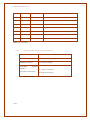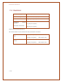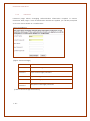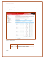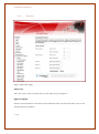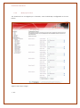
1
Smartmax Manual 8.0 1-- 1 - Smartmax Manual 8.0 TABLE OF CONTENTS 1 CONTACT INFORMATION .............................................................................................1-- 6 - 2 RF EXPOSURE AND ELECTRICAL SAFETY COMPLIANCE .............................................2-- 7 2.1 Caution ...........................................................................................................2-- 7 - 2.2 General Safety ...............................................................................................2-- 8 - 2.3 Vehicle Safety ................................................................................................2-- 9 - 2.4 Potentially Unsafe Areas ...............................................................................2-- 9 - 3 REVISION HISTORY ......................................................................................................3-- 10 - 4 SMARTMAX USER MANUAL ........................................................................................4-- 11 4.1 5 6 Disclaimers ...................................................................................................4-- 11 - INTRODUCTION ...........................................................................................................5-- 12 5.1 Overview ......................................................................................................5-- 12 - 5.2 Smartmax Features .....................................................................................5-- 13 - HARDWARE ..................................................................................................................6-- 16 6.1 Front Panel ....................................................................................................6-- 16 - 6.2 Side Panel (Left) ...........................................................................................6-- 17 6.2.1 RS-485 ............................................................................................................ 6-- 17 - 6.2.2 RS-232 ............................................................................................................ 6-- 18 - 6.2.3 mini USB (for debugging) ........................................................................... 6-- 19 - 6.2.4 I/O Interface – PIN Description ................................................................. 6-- 19 - 6.2.5 Power – Molex Connector (7 to 34 VDC) ............................................... 6-- 20 - 6.3 7 Side Panel (Right) ........................................................................................6-- 21 6.3.1 Reset .............................................................................................................. 6-- 21 - 6.3.2 LAN ................................................................................................................. 6-- 22 - 6.3.3 SIM Card ....................................................................................................... 6-- 22 - 6.3.4 3G FME Male Antenna Connector .......................................................... 6-- 22 - SPECIFICATIONS .........................................................................................................7-- 23 7.1 Hardware ......................................................................................................7-- 23 - 7.2 Mechanical ..................................................................................................7-- 24 - 7.3 Environmental ..............................................................................................7-- 24 - 7.4 Electrical .......................................................................................................7-- 25 - 7.5 Block Diagram .............................................................................................7-- 26 - 7.6 Mechanical Diagrams ................................................................................7-- 27 - 1-- 2 - Smartmax Manual 8.0 8 9 PROTOCOLS & ENCRYPTIONS ....................................................................................8-- 29 8.1 PPP (Point-to-Point Protocol) ......................................................................8-- 29 - 8.2 PPPoE (Point-to-Point Protocol over Ethernet) ..........................................8-- 29 - 8.3 DHCP (Dynamic Host Configuration Protocol) .........................................8-- 30 - 8.4 NAT (Network Address Translation or Translator) .....................................8-- 30 - 8.5 SNMP (Simple Network Management Protocol) ......................................8-- 31 - 8.6 SNTP (Simple Network Time Protocol) .......................................................8-- 32 - 8.7 ICMP (Internet Control Message Protocol) ...............................................8-- 33 - 8.8 NAT-T .............................................................................................................8-- 33 - 8.9 IKE ..................................................................................................................8-- 33 - 8.10 3DES ...............................................................................................................8-- 34 - 8.11 AES.................................................................................................................8-- 34 - 8.12 MD5 ...............................................................................................................8-- 34 - 8.13 SHA ................................................................................................................8-- 34 - 8.14 ISAKMP ..........................................................................................................8-- 34 - 8.15 ESM ................................................................................................................8-- 35 - 8.16 RIP (Routing Information Protocol) .............................................................8-- 35 - 8.17 DNP3 (Distributed Network Protocol) ........................................................8-- 36 - WEB INTERFACE ...........................................................................................................9-- 37 9.1 Configuration Page .....................................................................................9-- 38 9.1.1 Status ............................................................................................................. 9-- 38 - 9.1.2 LAN ................................................................................................................. 9-- 40 - 9.1.3 WAN ............................................................................................................... 9-- 41 - 9.1.4 Password ....................................................................................................... 9-- 50 - 9.1.5 Log Out ......................................................................................................... 9-- 51 - 9.1.6 Save & Reboot ............................................................................................ 9-- 51 - 9.2 1-- 3 - Configuration Page – Advanced...............................................................9-- 52 9.2.1 Dynamic DNS ............................................................................................... 9-- 52 - 9.2.2 DMZ ................................................................................................................ 9-- 53 - 9.2.3 IP Filtering ...................................................................................................... 9-- 54 - 9.2.4 MAC Filtering ................................................................................................ 9-- 56 - 9.2.5 Port forwarding ............................................................................................ 9-- 58 - 9.2.6 VPN ................................................................................................................ 9-- 59 - 9.2.7 Ping Tool ........................................................................................................ 9-- 61 - 9.2.8 SNMP .............................................................................................................. 9-- 62 - Smartmax Manual 8.0 9.2.9 Setting SNMP Agent .................................................................................... 9-- 64 - 9.2.10 SNMP Custom MIB .................................................................................. 9-- 66 - 9.2.11 IP Stack ..................................................................................................... 9-- 68 - 9.3 Configuration Page – Administrator ..........................................................9-- 70 9.3.1 AT .................................................................................................................... 9-- 70 - 9.3.2 Backup (Save/Reload) .............................................................................. 9-- 72 - 9.3.3 System Logs .................................................................................................. 9-- 74 - 9.3.4 Time Zone...................................................................................................... 9-- 75 - 9.3.5 System ........................................................................................................... 9-- 77 - 9.3.6 Upgrade Firmware ...................................................................................... 9-- 79 - 9.4 Configuration Page – Expansion I/O Board .............................................9-- 81 9.4.1 Status ............................................................................................................. 9-- 81 - 9.4.2 I/O Automation ........................................................................................... 9-- 82 - 9.4.3 Digital I/O Scheduler .................................................................................. 9-- 84 - 9.4.4 Digital I/O Web Automation ..................................................................... 9-- 84 - 9.4.5 Output Pulse ................................................................................................. 9-- 86 - 9.4.6 SMS Output ................................................................................................... 9-- 88 - 9.4.7 SMS Input ...................................................................................................... 9-- 89 - 9.4.8 SMS Analog .................................................................................................. 9-- 90 - 9.4.9 SMS Pulse ...................................................................................................... 9-- 94 - 9.5 Smartmax DNP3 Configurations – Point Configurations ..........................9-- 95 9.5.1 Analogue Input Points ................................................................................ 9-- 95 - 9.5.2 Binary Input Points ....................................................................................... 9-- 98 - 9.5.3 Binary Output Points ................................................................................. 9-- 101 - 9.5.4 Counter Points ........................................................................................... 9-- 103 - 9.5.5 Internal Points ............................................................................................. 9-- 106 - 9.6 Smartmax DNP3 Configurations – DNP3 Configurations .......................9-- 108 - 9.7 Smartmax DNP3 Configurations – DNP3 Events .....................................9-- 111 - 1-- 4 - 9.7.1 Binary Event Variation .............................................................................. 9-- 113 - 9.7.2 Integer Event Variation ............................................................................ 9-- 113 - 9.7.3 Float Event Variation ................................................................................ 9-- 114 - 9.7.4 Counter Event Variation .......................................................................... 9-- 114 - 9.7.5 Frozen Counter Event Variation ............................................................. 9-- 115 - 9.7.6 Class Max. Events ...................................................................................... 9-- 115 - 9.7.7 Class Max. Delays ..................................................................................... 9-- 115 - Smartmax Manual 8.0 9.8 Smartmax DNP3 Configurations - TCP/IP Configurations......................9-- 116 9.8.1 Network Type ............................................................................................. 9-- 116 - 9.8.2 IP Address of DNP3 Master ...................................................................... 9-- 117 - 9.8.3 Validate UDP Source Address ................................................................ 9-- 117 - 9.8.4 TCP Listen Port Number ............................................................................ 9-- 117 - 9.8.5 Local UDP Port Number ........................................................................... 9-- 117 - 9.8.6 Initial UDP Unsolicited Port Number ....................................................... 9-- 118 - 10 Additional Information .................................................................................. 10-- 119 10.1 SMS Commands ..................................................................................... 10-- 119 - 10.2 Backing up configurations on to a FTP Server ..................................... 10-- 121 - 10.3 UDP Keep Alive and Wake up Settings ................................................ 10-- 122 - 10.4 Auto Reboot for Signal or Registration Issue ....................................... 10-- 122 - 1-- 5 - Smartmax Manual 8.0 1 CONTACT INFORMATION In keeping with Maxon's dedicated customer support policy, we encourage you to contact us. TECHNICAL: Hours of Operation: Monday to Friday 8.30am to 5.30pm* Telephone: +61 2 8707 3000 Facsimile: +61 2 8707 3001 Email: [email protected] * Public holidays excluded SALES: Hours of Operation: Monday to Friday 8.30am to 5.30pm* Telephone: +61 2 8707 3000 Facsimile: +61 2 8707 3001 Email: [email protected] WEBSITE: www.maxon.com.au * Public holidays excluded Maxon has also added for the benefit of developers and integrators, a forum on our website that can be accessed to discuss this product and/or technical matters in relation to your applications. All questions raised within this portal will be answered. FORUM: www.maxon.com.au/forum ADDRESS: Maxon Australia Pty Ltd 36a Gibson Avenue, Padstow Sydney, NSW, Australia 2211 POSTAL ADDRESS: Maxon Australia Pty Ltd Po Box 1, Revesby North, Sydney, NSW Australia 2212 1-- 6 - Smartmax Manual 8.0 2 RF EXPOSURE AND ELECTRICAL SAFETY COMPLIANCE The use of this device in any other type of host configuration may not comply with the RF exposure requirements and should be avoided. During operation, a 20 cm separation distance should be maintained between the antenna, whether extended or retracted, and the user’s/bystander’s body (excluding hands, wrists, feet, and ankles) to ensure RF exposure compliance. The modem is not designed for, nor intended to be, used in applications within 20 cm (8 inches) of the body of the user. Continued compliance of the equipment relies upon it being used with an AS/NZS 60950.1 approved SELV power supply. 2.1 Caution Change or modification without the express consent of Maxon Australia Pty. Ltd. voids the user’s authority to use the equipment. These limits are designed to provide reasonable protection against harmful interference in an appropriate installation. The modem is a transmitting device with similar output power to a mobile phone. This equipment generates, uses, and can radiate radio frequency energy and, if not used in accordance with instructions, can cause harmful radiation to radio communication. Use only the supplied or an approved antenna. Unauthorized antennas, modifications, or attachments could impair call quality, damage the device, or result in violation of RF exposure regulations. However, there is no guarantee that interference will not occur in a particular installation. If the equipment does cause harmful interference in radio and television reception, which can be determined by turning the equipment on and off, the user is encouraged to try to correct the interference by one or more of the following measures: 1-- 7 - Re-orient or relocate the receiving radio or TV antenna Increase the separation distance between the equipment and the receiver Contact Maxon Australia Technical Support for assistance. Smartmax Manual 8.0 2.2 General Safety RF Interference Issues: Avoid possible radio frequency (RF) interference by carefully following safety guidelines below: Switch OFF the Modem when in an aircraft. The use of cellular telephones in aircraft is illegal. It may endanger the operation of the aircraft and/or disrupt the cellular network. Failure to observe this instruction may lead to suspension or denial of cellular services to the offender, legal action, or both. Switch OFF the Modem in the vicinity of gasoline or diesel fuel pumps or before filling a vehicle with fuel. Switch OFF the Modem in hospitals and any other place where medical equipment may be in use. Respect restrictions on the use of radio equipment in fuel depots, chemical plants, or in areas of blasting operations. There may be a hazard associated with the operation of your Modem in the vicinity of inadequately protected personal medical devices such as hearing aids and pacemakers. Please consult the manufacturers of the medical device to determine if it is adequately protected. Operation of the Modem in the vicinity of other electronic equipment may cause interference if the equipment is inadequately protected. Observe any warning signs and manufacturers’ recommendations. The modem contains sensitive electronic circuitry. Do not expose the modem to any liquids, high temperatures or shock. The modem is not waterproof. Please keep it dry and store it in a cool, dry place. Only use original accessories or accessories that are authorized by the manufacturer. Using unauthorized accessories may affect your modem’s performance, damage your modem and violate related national regulations. Always handle the modem with care. There are no user serviceable parts inside the modem. Unauthorised dismantling or repair of the modem will void the warranty. 1-- 8 - Smartmax Manual 8.0 2.3 Vehicle Safety Do not use the Modem while driving. Respect national regulations on the use of cellular telephones in vehicles. Road safety always comes first. If incorrectly installed in a vehicle, the operation of the Modem could interfere with the correct functioning of vehicle electronics. To avoid such problems, be sure that the installation has been performed by qualified personnel. Verification of the protection of vehicle electronics should be part of the installation. Note: The user is cautioned that changes or modifications not expressly approved by Maxon Australia could void the warrantee. 2.4 Potentially Unsafe Areas Posted Facilities: Turn off this device in any facility or area when posted notices require you to do so. Blasting Areas: Turn off your device where blasting is in progress. Observe restrictions and follow any regulations or rules. Potentially Explosive Atmospheres: Turn off your device when you are in any area with a potentially explosive atmosphere. Obey all signs and instructions. Sparks in such areas could cause an explosion or fire, resulting in bodily injury or death. Areas with a potentially explosive atmosphere are often but not always clearly marked. They include: fuelling areas such as gas or petrol stations below deck on boats transfer or storage facilities for fuel or chemicals vehicles using liquefied petroleum gas, such as propane or butane areas when the air contains chemicals or particles such as grain, dust or metal powders avoid using the modem in areas that emit electromagnetic waves or enclosed metallic structures e.g. lifts. 1-- 9 - any other area where you would normally be advised to turn off your engine Smartmax Manual 8.0 3 REVISION HISTORY Product Smartmax M2M HSPA Smart Modem Solution Model MA-2010 Document Type FDS Current Version Number 8.0 Status of the Document Public Release Revision Date July 2013 Total Number of Pages 100 - Revision History Level Date History 1.0 Sep 2010 Internal/Public Release Version 2.0 Feb 2011 Public Release Version SIM PIN enable/Disable- Under WAN page Available Network Search – Under WAN page Advanced Port forwarding – Under Advanced 3.0 April 2012 Output pulse - Under Expansion Board Multiple output change via one sms 6.0 December 2012 Updated SMS Analog page 7.0 April 2013 Updated screenshots and cleaned up 8.0 July 2013 Major clean up and addition of new screenshots for improvements to Output SMS, Input SMS 6 numbers, IO Automation url and turn on by SMS 1-- 10 - Smartmax Manual 8.0 4 SMARTMAX USER MANUAL All data and information contained in or disclosed by this document are confidential and proprietary information of Maxon Australia, and all rights therein are expressly reserved. By accepting this material, the recipient agrees that this material and the information contained therein are held in confidence and in trust and will not be used, copied, reproduced in whole or in part, nor its contents revealed in any manner to others without the express written permission of Maxon Australia. This information provided in this document is provided on an “as is” basis. In no event will Maxon Australia be liable for any damages arising directly or indirectly from any use of information contained in this document. Information in this document is preliminary and subjected to change without any notice. 4.1 Disclaimers Life support – This product is not designed for use in life support appliances or systems where malfunction of these products can reasonably be expected to result in personal injury. Maxon Australia customers using or selling these products for use in such applications do so at their own risk and agree to fully indemnify Maxon Australia for any damages resulting from such application. Right to make change - Maxon Australia reserves the right to make changes, without notice, in the products, including circuits and software, described or contained herein in order to improve design and/or performance. 1-- 11 - Smartmax Manual 8.0 5 INTRODUCTION 5.1 Overview Breaking the industry benchmark, the top-of-the range Smartmax is a unique and intelligent fusion of 3G capabilities with advanced functionality of a modem/router, complete with built-in DNP3; all encased in a durable & robust metal casing. The Smartmax has an array of industrial connectivity options, including RS232, RS485 & USB ports. DNP3 protocol and HSPA wireless connectivity to ensure local, national and international remote access via VPN, DDNS & FTP features. Complete with SCADA functionality capabilities, the Smartmax can power up simple to advanced M2M applications, enabling secure and two-way communications for remote monitoring, control, management and reporting. Designed for reliable field performance and functionalities, the Smartmax allow solutions to deliver rapid, costeffective deployment for any telemetry environments. With the additional I/O Board, the Smartmax transforms into a standalone RTU (Remote Terminal Unit), being an all-in-one solution to streamline your data telemetry to the next generation. 1-- 12 - Smartmax Manual 8.0 5.2 Smartmax Features General Features HSPA Wireless Module Em-770w PCI (7.2Mbps downlink, 2Mbps uplink) Supports Packet and Circuit Switched Data Built in Web Interface USB, RS232 and RS485 connection 2 Way SMS Remote SMS diagnostics & reset Embedded TCP/IP, UDP/IP STACK In-built periodic reset External DC Powered Support VPN Server and Client Mode Dynamic DNS Supports DNP3 (Outstation) using extension I/O board. Rugged Metal Casing for industrial use Programmable periodic reset Programmable scheduler to control WAN connection Telnet support Save and restore modem configuration from a file FOTA - Firmware upgrade over the air External antenna connectivity to maximise HSPA coverage External LED to show Network and Connection status Frequency Bands WCDMA/HSPA 850MHz, 1900MHz, 2100MHz GSM/GPRS/EDGE 850MHz, 900MHz, 1800MHz and 1900MHz Data Speeds WCDMA PS: UL 384 Kbps / DL 384 Kbps WCDMA CS: UL 64 Kbps / DL 64 Kbps GPRS/EDGE: UL 236 Kbps / DL 236 Kbps GSM CS: 1-- 13 - UL 9.6 Kbps / DL 9.6 Kbps Smartmax Manual 8.0 Environmental Specifications Normal Operation Temperature Extreme Operation Temperature -20 to 60° C -25 to 75° C Dimensions 93mm x 150mm x 25mm (without side brackets and antenna) Connections RS232 Connection RS485 Connection USB Connection SIM Card Holder I/O Port External Power Connection (Molex) Diagnostics Antenna connector: FME male Mounting Side mounting brackets LED Lights Power Data RX TX Module Approvals GCF PTCRB CE FCC ACA 1-- 14 - Smartmax Manual 8.0 Carrier Approvals* - (Please contact Maxon Australia for more information) Compliance RoHS Compliant Power Source DC Input Voltage Range: 7 to 34 VDC Idle Current @ 12V: 30mA Maximum Current @ 12V: 200mA Operating Systems 1-- 15 - Microsoft Windows, Mac OS, Linux, Win CE Smartmax Manual 8.0 6 HARDWARE 6.1 Front Panel LEDs LED Power Data DISPLAY DESCRIPTION ON Indicates main power is ON OFF Indicates main power is OFF Solid ON Indicates signal is good (RSSI ≥ -90 dBm) 1200ms ON and 1200ms OFF Indicates signal is marginal (-91dBm ≥ RSSI ≥ -105 dBm) 2500ms OFF and 100ms ON Indicates signal is poor (RSSI ≤ -105dBm) 2500ms ON and 100ms OFF Indicates Packet Data connection mode 100ms ON and 100ms OFF Indicates Circuit Switched connection mode with data communication [Table 1: LED Display] * Please note that in Modem Router Mode the Data LED will always be off. 1-- 16 - Smartmax Manual 8.0 6.2 Side Panel (Left) 1 6.2.1 2 4 5 RS-485 ITEM DESCRIPTION TX- Inverting RS-485/422 Driver Output TX+ Non-inverting RS-485/422 Driver Output RX- Inverting RS-485/422 Receiver Input RX+ Non-inverting RS-485/422 Receiver Input Input voltage range -7V~+12V Input resistance 96KΩ Minimum driver output range +-1.5V Maximum driver output range +-5V Output short-circuit current +-250mA [Table: RS-485] 1-- 17 - 3 Smartmax Manual 8.0 6.2.2 RS-232 PIN ITEM DESCRIPTION 1 DCD The On condition on this signal line, as sent by the MT2, informs TE2 that it is receiving a carrier signal from the remote TE2 that meets its criteria. 2 RXD Receiving serial data signal to TE2 3 TXD Sending serial data signal from TE2 4 GND Ground 5 VCC Power supply for the modem (7 ~ 34) VDC power output 6 DSR This signal, in conjunction with DTR, indicates equipment readiness. DSR is turned ON by the MT2 to indicate to the TE2 it is ready to receive or transmit data. 7 RTS The signal is turned ON by the TE2 to indicate now it is ready to receive data. (In the case of Hardware flow control) 8 CTS The signal is turned ON by the MT2 to indicate now it is ready to transmit data. (In the case of Hardware flow control) 9 RESET This input will reboot the Smartmax. Active Low 10 RI The ring indicator is turned on by the MT2. Module informs TE2 of incoming voice or data calls. 11 Console_TXD Console/diagnostics - Sending serial data 12 Console_RXD Console/diagnostics - Receiving serial data 13 DTR This is a signal turned ON by the TE2 to indicate to the MT2 that it is connected to the line 14 GND Ground 15 Cable detect Indicate assembling a cable [Table: RS-232] 1-- 18 - Smartmax Manual 8.0 6.2.3 mini USB (for debugging) 6.2.4 I/O Interface – PIN Description Pin Name Direction Electrical spec 1 VDD33 Output 3.3VDC / Max. 100mA 2 VDD33 Output 3.3VDC / Max. 100mA 3 ANALOG2 Input 0~12V 4 GND Ground - 5 ANALOG1 Input 0~20mA/0~5V/0~10V 6 GND Ground - 7 ANALOG0 Input 0~20mA/0~5V/0~10V 8 GND Ground - 9 INPUT5 Input High:2.5~4V Low: 0~0.9V 10 INPUT6 Input High:2.5~4V Low: 0~0.9V 11 INPUT4 Input High:2.5~4V Low: 0~0.9V 12 OUTPUT0 Output High:3.3V Low: 0V 1-- 19 - Smartmax Manual 8.0 13 INPUT3 Input High:2.5~4V Low: 0~0.9V 14 OUTPUT1 Output High:3.3V Low: 0V 15 INPUT2 Input High:2.5~4V Low: 0~0.9V 16 OUTPUT2 Output High:3.3V Low: 0V 17 INPUT1 Input High:2.5~4V Low: 0~0.9V 18 OUTPUT3 Output High:3.3V Low: 0V 19 INPUT0 Input High:2.5~4V Low: 0~0.9V 20 OUTPUT4 Output High:3.3V Low: 0V [Table: I/O Interface] 6.2.5 Power – Molex Connector (7 to 34 VDC) DC Input Voltage + 7 ~ +34 [VDC] Internal Voltage +1.8, +2.5, +3.3, +5 [VDC] Maximum Current 450 [mA] @ 12[VDC] Operating Standby Current PKT Data Connection [Table: Power] 1-- 20 - 45 [mA] @ 12 [VDC] 150 [mA] @ 12 [VDC] Smartmax Manual 8.0 6.3 Side Panel (Right) 1 6.3.1 2 3 Reset Press the factory reset switch and hold in for 20 seconds. 1-- 21 - 4 Smartmax Manual 8.0 6.3.2 LAN 6.3.3 SIM Card 6.3.4 3G FME Male Antenna Connector 1-- 22 - Smartmax Manual 8.0 7 SPECIFICATIONS 7.1 Hardware ITEM DESCRIPTION Product SMARTMAX Industrial HSUPA Ethernet Router User MCU 32-bit RISC Processor System Clock 200 MHz Program Memory 32 MB (SDRAM) Data Memory 64 MB (Nand - Flash) Wireless Interface HSPA WCDMA Module HSPA Mini PCI Express Module EM-770W PCI Communication 1 RS 232 Port 1 RS 485 Port Digital I/O Port 6 Digital Inputs, 4 Digital Outputs, 3 Analog Inputs Diagnostic 1 mini USB Connector LAN 1 Port 10/100Mbps Ethernet Antenna Connector FME Male Display 4 Status LED’s Ext Power Connector Molex R-UIM Support [Table: Hardware Specifications] 1-- 23 - Smartmax Manual 8.0 7.2 Mechanical Dimension 98 x 151 x 25.5 [mm](with side bracket) Weight 236g Approx Housing Material Aluminum [Table: Mechanical Specifications] 7.3 Environmental Operating Temp - 10 ~ + 70 [°C] Extreme Temp - 25 ~ + 75 [°C] Operating Storage Temp - 30 ~ + 80 [°C] Humidity 5% ~ 95% non-condensing [Table: Environmental Specifications] 1-- 24 - Smartmax Manual 8.0 7.4 Electrical DC Input Voltage + 7 ~ +34 [VDC] Internal Voltage +1.8, +2.5, +3.3, +5 [VDC] Maximum Current 450 [mA] @ 12[VDC] Operating Standby Current PKT Data Connection 45 [mA] @ 12 [VDC] 150 [mA] @ 12 [VDC] [Table: Electrical Specifications] The current draw for the Unimax with the I/O Board is as follows: 45 [mA] @ 12 [VDC] Idle 50 [mA] @ 12 [VDC] with outputs ON 60 [mA] @ 12 [VDC] Active 90 [mA] @ 12 [VDC] 1-- 25 - with outputs ON Smartmax Manual 8.0 7.5 Block Diagram 1-- 26 - Smartmax Manual 8.0 7.6 Mechanical Diagrams 1-- 27 - Smartmax Manual 8.0 1-- 28 - Smartmax Manual 8.0 8 PROTOCOLS & ENCRYPTIONS 8.1 PPP (Point-to-Point Protocol) PPP (Point-to-Point Protocol) is a protocol for communication between two computers using a serial interface, typically a personal computer connected by phone line to a server. For example, your Internet service provider may provide you with a PPP connection so that the provider's server can respond to your requests, pass them on to the Internet, and forward the requested Internet responses back to you. PPP uses the Internet protocol (IP) and is designed to handle others. It is sometimes considered a member of the TCP/IP suite of protocols. Relative to the Open Systems Interconnection (OSI) reference model, PPP provides layer 2 (data-link layer) services. Essentially, it packages your computer's TCP/IP packets and forwards them to the server where they can actually be put on the Internet. PPP is a full-duplex protocol that can be used on various physical media, including twisted pair or fiber optic lines or satellite transmission. It uses a variation of High Speed Data Link Control (HDLC) for packet encapsulation. 8.2 PPPoE (Point-to-Point Protocol over Ethernet) PPPoE (Point-to-Point Protocol over Ethernet) is a specification for connecting multiple computer users on an Ethernet local area network to a remote site via a modem. PPPoE can be used to have an office or building-full of users share a common Digital Subscriber Line (DSL), cable modem, or wireless connection to the Internet. PPPoE combines the Point-to-Point Protocol (PPP), commonly used in dialup connections, with the Ethernet protocol, which supports multiple users in a local area network. The PPP protocol information is encapsulated within an Ethernet frame. PPPoE has the advantage that neither the telephone company nor the Internet service provider (ISP) needs to provide any special support. Unlike dialup connections, DSL and cable modem connections are "always on." Since a number of different users are sharing the same physical connection to the remote service provider, a way is needed 1-- 29 - Smartmax Manual 8.0 to keep track of which user traffic should go to and which user should be billed. PPPoE provides for each user-remote site session to learn each other's network addresses (during an initial exchange called "discovery"). Once a session is established between an individual user and the remote site (for example, an Internet service provider), the session can be monitored for billing purposes. 8.3 DHCP (Dynamic Host Configuration Protocol) DHCP (Dynamic Host Configuration Protocol) is a communication protocol that lets network administrators centrally manage and automate the assignment of Internet Protocol (IP) addresses in an organization's network. Using the Internet Protocol, each machine that connects to the Internet needs a unique IP address, which is assigned when an Internet connection is created for a specific computer. Without DHCP, the IP address must be entered manually at each computer in an organization and a new IP address must be entered each time a computer moves to a new location on the network. DHCP lets a network administrator supervise and distribute IP addresses from a central point and automatically sends a new IP address when a computer is plugged into a different place in the network. DHCP uses the concept of a "lease" or amount of time that a given IP address will be valid for a computer. The lease time can vary depending on how long a user requires the Internet connection at a particular location. It's especially useful in education and other environments where users change frequently. Using very short leases, DHCP can dynamically reconfigure networks in which there are more computers than there are available IP addresses. The protocol also supports static addresses for computers that need a permanent IP address, such as Web servers. 8.4 NAT (Network Address Translation or Translator) NAT (Network Address Translation or Network Address Translator) is the translation of an Internet Protocol address (IP address) used within one network to a different IP address known within another network. One network is designated as the inside network and the other as the outside. Typically, a company maps its local inside network addresses to one or more global outside IP addresses and un-maps the global IP addresses on 1-- 30 - Smartmax Manual 8.0 incoming packets back into local IP addresses. This helps ensure security since each outgoing or incoming request must go through a translation process that also offers the opportunity to qualify or authenticate the request or match it to a previous request. NAT also conserves on the number of global IP addresses that a company needs and it lets the company use a single IP address in its communication with the world. NAT is included as part of a router and is often part of a corporate firewall. Network administrators create a NAT table that does the global-to-local and local-to-global IP address mapping. NAT can also be used in conjunction with policy routing. NAT can be statically defined or it can be set up to dynamically translate from and to a pool of IP addresses. NAT lets an administrator create tables that map: A local IP address to one global IP address statically A local IP address to any of a rotating pool of global IP addresses that a company may have A local IP address plus a particular TCP port to a global IP address or one in a pool of them A global IP address to any of a pool of local IP addresses on a round-robin basis NAT is described in general terms in RFC 1631, which discusses NAT's relationship to Classless Inter-domain Routing (CIDR) as a way to reduce the IP address depletion problem. NAT reduces the need for a large amount of publicly known IP addresses by creating a separation between publicly known and privately known IP addresses. CIDR aggregates publicly known IP addresses into blocks so that fewer IP addresses are wasted. 8.5 SNMP (Simple Network Management Protocol) Simple Network Management Protocol (SNMP) is the protocol governing network management and the monitoring of network devices and their functions. It is not necessarily limited to TCP/IP networks. 1-- 31 - Smartmax Manual 8.0 8.6 SNTP (Simple Network Time Protocol) Simple Network Time Protocol (SNTP) is a protocol that is used to synchronize computer clock times in a network of computers. In common with similar protocols, SNTP uses Coordinated Universal Time (UTC) to synchronize computer clock times to a millisecond, and sometimes to a fraction of a millisecond. Accurate time across a network is important for many reasons; even small fractions of a second can cause problems. For example, distributed procedures depend on coordinated times to ensure that proper sequences are followed. Security mechanisms depend on coordinated times across the network. File system updates carried out by a number of computers also depend on synchronized clock times. Air traffic control systems provide a graphic illustration of the need for coordinated times, since flight paths require very precise timing (imagine the situation if air traffic controller computer clock times were not synchronized). UTC time is obtained using several different methods, including radio and satellite systems. Specialised receivers are available for high-level services such as the Global Positioning System (GPS). However, it is not practical or cost-effective to equip every computer with one of these receivers. Instead, computers designated as primary time servers are outfitted with the receivers and they use protocols such as SNTP to synchronize the clock times of networked computers. Degrees of separation from the UTC source are defined as strata. A radio clock (which receives true time from a dedicated transmitter or satellite navigation system) is stratum-0; a computer that is directly linked to the radio clock is stratum-1; a computer that receives its time from astratum-1 computer is stratum-2, and so on. The term SNTP applies to both the protocol and the client/server programs that run on computers. The programs are compiled by the user as an SNTP client, SNTP server, or both. In basic terms, the SNTP client initiates a time request exchange with the time server. As a result of this exchange, the client is able to calculate the link delay, its local offset, and adjust its local clock to match the clock at the server's computer. As a rule, six exchanges over a period of about five to 10 minutes are required to initially set the clock. Once synchronized, the client updates the clock about once every 10 minutes, usually requiring only a single message exchange. Redundant servers and varied 1-- 32 - Smartmax Manual 8.0 network paths are used to ensure reliability and accuracy. In addition to client/server synchronization, SNTP also supports broadcast synchronization of peer computer clocks. SNTP is designed to be highly fault-tolerant and scalable. 8.7 ICMP (Internet Control Message Protocol) ICMP (Internet Control Message Protocol) is a message control and error-reporting protocol between a host server and a gateway to the Internet. ICMP uses Internet Protocol - IP data-grams, but the messages are processed by the IP software and are not directly apparent to the application user. 8.8 NAT-T NAT-T (NAT Traversal in the IKE) is a method of enabling IPSec-protected IP datagram’s to pass through a Network address translator (NAT). An IP packet is modified while passing through a network address translator device in a manner that is incompatible with Internet Protocol Security (IPSec). NAT-T protects the original IPSec encoded packet by encapsulating it with another layer of UDP and IP headers. The negotiation during the Internet key exchange (IKE) phase is defined in RFC 3947 and the UDP encapsulation itself is defined in RFC 3948. Most major networking vendors support NATT for IKEv1 in their devices. In Microsoft Windows XP with Service Pack 2 the feature can be enabled. 8.9 IKE Internet Key Exchange (IKE or IKEv2) is the protocol used to set up a security association (SA) in the IPSec protocol suite. IKE uses a Diffie-Hellman key exchange to set up a shared session secret, from which cryptographic keys are derived. Public key techniques or, alternatively, a pre-shared key, are used to mutually authenticate the communicating parties. 1-- 33 - Smartmax Manual 8.0 8.10 3DES The earliest standard that defines the algorithm describes it as the "Triple Data Encryption Algorithm (TDEA)" — i.e. three operations of the Data Encryption Algorithm specified in ANSI X3.92 — and do not use the terms "Triple DES" or "DES". 8.11 AES The Advanced Encryption Standard (AES) is an encryption standard adopted by the U.S. government. The standard comprises three block ciphers, AES-128, AES-192 and AES-256, adopted from a larger collection originally published as Rijndael. Each AES cipher has a 128-bit block size, with key sizes of 128, 192 and 256 bits. The AES ciphers have been analyzed extensively and are now used worldwide. 8.12 MD5 MD5 (Message-Digest algorithm 5) is a widely used cryptographic hash function with a 128-bit hash value. As an Internet standard (RFC 1321), MD5 has been employed in a wide variety of security applications, and is also commonly used to check the integrity of files. 8.13 SHA SHA stands for Secure Hash Algorithm. The three SHA algorithms are structured differently and are distinguished as SHA-0, SHA-1, and SHA-2. The SHA-2 family uses an identical algorithm with a variable digest size which is distinguished as SHA-224, SHA256, SHA-384, and SHA-512. 8.14 ISAKMP ISAKMP defines the procedures for authenticating a communicating peer, creation and management of Security Associations, key generation techniques, and threat mitigation (e.g. denial of service and replay attacks). ISAKMP typically utilizes IKE for key 1-- 34 - Smartmax Manual 8.0 exchange, although other methods can be implemented. 8.15 ESM Encapsulating Security Payload (ESP) is a member of the IPSec protocol suite. In IPSec, it provides origin authenticity, integrity, and confidentiality protection of packets. ESP also supports encryption-only and authentication-only configurations, but using encryption without authentication is strongly discouraged because it is insecure. Unlike Authentication Header (AH), ESP does not protect the IP packet header. However, in Tunnel Mode, where the entire original IP packet is encapsulated with a new packet header added, ESP protection is afforded to the whole inner IP packet (including the inner header) while the outer header remains unprotected. ESP operates directly on top of IP, using IP protocol number 50. 8.16 RIP (Routing Information Protocol) RIP is a distance-vector routing protocol, which employs the hop count as a routing metric. The hold down time is 180 seconds. RIP prevents routing loops by implementing a limit on the number of hops allowed in a path from the source to a destination. The maximum number of hops allowed for RIP is 15. This hop limit, however, also limits the size of networks that RIP can support. A hop count of 16 is considered an infinite distance and used to deprecate inaccessible, inoperable, or otherwise undesirable routes in the selection process. There are three versions of RIP. Smartmax supports RIPv2. Due to the deficiencies of the original RIP specification, RIP version 2 (RIPv2) was developed in 1993 and last standardized in 1998. It included the ability to carry subnet information, thus supporting Classless Inter-Domain Routing (CIDR). To maintain backward compatibility, the hop count limit of 15 remained. RIPv2 has facilities to fully interoperate with the earlier specification if all Must Be Zero protocol fields in the RIPv1 messages are properly specified. In addition, a compatibility switch feature allows finegrained interoperability adjustments. 1-- 35 - Smartmax Manual 8.0 8.17 DNP3 (Distributed Network Protocol) Distributed Network Protocol - DNP3 - is a set of communications protocols used between components in process automation systems. Specifically, it was developed to facilitate communications between various types of data acquisition and control equipment. It plays a crucial role in SCADA systems, where it is used by SCADA Master Stations, Remote Terminal Units (RTU), and Intelligent Electronic Devices (IED). It is primarily used for communications between a master station and RTUs or IEDs. ICCP, the Inter-Control Centre Protocol, is used for inter-master station communications. 1-- 36 - Smartmax Manual 8.0 9 WEB INTERFACE Smartmax can be configured through its web interface. Smartmax Web-based Configuration Page (192.168.0.1) [Figure: Web-based configuration of Smartmax] Power ON the Smartmax Router and connect to a computer using a mini USB cable via the LAN port o the Smartmax. Install the USB to Ethernet driver from the CD provided with the Smartmax box. To launch the web interface of the Smartmax, open a web browser such as Internet explorer for Windows and type the following IP address in the address bar: [Figure: Web-based configuration page address] Enter username and password in the pop-up window that prompts for login details. Username and password is “admin’ by default. This default username and password can be changed through the Password Setup Page. 1-- 37 - Smartmax Manual 8.0 [Figure: Log-in window] The Status page of Smartmax web interface will come up with device and connection information. 9.1 Configuration Page 9.1.1 Status Status page displays the current status of LAN, WAN and Network Information. [Figure: Status Page] 1-- 38 - Smartmax Manual 8.0 ITEM DESCRIPTION Up Time Operation time after power up System Time System time acquired from HSPA modem IMEI IMEI number of the Smartmax HSPA Version Current firmware version of Smartmax Router HSPA Module Version Current Firmware version of the 3G module inside Smartmax Router WAN Current operation mode i.e. Modem Router Network Registration Status of the 3G module including registration PIN Status Status of PIN request (enable/disable) Signal Level Status of current signal strength(dBm) WAN IP IP address assigned by ISP such as Telstra or Optus Netmask Subnet Mask assigned by ISP such as Telstra or Optus Send/Receive Status of Incoming and Outgoing WAN data packets. This is for information purpose only and should not be used for billing purposes. Packets LAN Smartmax IP address IP Netmask Subnet Mask assigned by Smartmax for LAN MAC MAC address of Smartmax LAN adaptor Send/Receive Status of Incoming and Outgoing LAN data packets Packets [Table: Status Page Information] 1-- 39 - Smartmax Manual 8.0 9.1.2 LAN LAN page allows configuring the IP address of Smartmax, DHCP range and viewing information of the clients connected on the Smartmax LAN port. [Figure: LAN Page] 1-- 40 - ITEM DESCRIPTION Smartmax Gateway IP Smartmax can be configured with a Static IP or can be set to obtain an IP address from an external DHCP Server (Client Mode) Ethernet Type Select USB Cable or USB Converter IP Address Configure Smartmax IP address Subnet Mask Configure the subnet mask Default Gateway Configure the Default Gateway IP address Smartmax Manual 8.0 DHCP DHCP Range Enable or Disable DHCP server of Smartmax Client Assign IP address range for DHCP Server of Smartmax [Table: LAN Page Information] 9.1.3 WAN WAN page allows configuring network authentication information, connection retrial and Scheduler timers. [Figure: WAN Page] 1-- 41 - Smartmax Manual 8.0 ITEM DESCRIPTION Select the mode for Smartmax to connect in i.e. Mode Modem Router, IP Stack Auto or Manual Profile Select a predefined profile or create one using the custom option APN Name Select APN Name provided by the ISP Dialup Telephone number to dial Auto PIN 1-- 42 - Smartmax will automatically enter the PIN code if the PIN request on the USIM card is enabled. Please enter correct PIN code as incorrect PIN Smartmax Manual 8.0 code will lock the SIM card. Power Reset Smartmax daily Set from 1 to 24 hours Periodic Reset Enable/Disable – Reset TCP Server Listening Enable/Disable – Reset TCP Connected State Enable/Disable – Reset DNP3 Idle State PIN Enable Enable USIM PIN PIN Disable Tick the box provided, enter your pin and apply the setting, to disable SIM PIN untick the box, enter your pin and apply the settings. Search Available network This feature will search the available network. Please note that the modem will drop the internet connection when network search is performed. After selecting the preferred network, please select save and reboot to save the settings. Band A particular band can be selected or left on Auto using this option User Name Password Password provided by the ISP MTU Define Maximum Transmission Unit size for Smartmax Authentication Select Authentication scheme used by the ISP PPP Echo LCP echo interval time can be set by the user. This option checks the status of the PPP connection. Check PING Check 1-- 43 - Username provided by the ISP Ping Check settings allow pinging 2 designated servers at set intervals. Smartmax Manual 8.0 Smartmax will disconnect WAN connection and performs a power reset if the ping fail count expires for both servers Smartmax will start a back off algorithm on power up as set by these times instead of constantly retrying PPP connection. Smartmax will reset if PPP connection is not successful after 2nd retrial timer has expired and start again. 1st Retrial when disconnected. Back Off wireless network gets Interval: Retrial interval time (Second) During time: Continuing time (Minute) 2nd Retrial after 1st retrial is unsuccessful Interval: Retrial interval time (Minute) During time: Continuing time (Hour) Scheduler Smartmax establishes WAN connection (Router Mode) between the times specified above. Disabling this function allows Smartmax to be online at all times RS232 Control Switch OFF RS232 when HSPA module is turned OFF as set per the Scheduler settings. [Table: WAN Page Information] Operating Modes Smartmax operates in the following three modes: Modem Router In this mode the Smartmax will automatically establish WAN connection. Serial Port doesn’t work in this mode. Internal DNP3 will work with I/O board. Please note that Bridge mode is not supported on the SMARMAX. 1-- 44 - Smartmax Manual 8.0 IPStack Auto In this mode Smartmax will behave same as the Modmax IPStack Auto mode. It will initiate the PPP connection and start the socket connection as a Server or Client as per the IPStack page setup. This applies for both RS485 and RS232 ports and the ports can be specified on the IPStack page under Administrator via the web interface. IPStack Manual In this mode Smartmax will behave same as the Modmax where the TE (Terminal Equipment) have to initiate (at$$ipctos) and drop the connection (at$$ipctcs). IPStack Manual mode gets its configuration from the IPStack page under Administrator via the web interface. Following are the AT Commands supported by the Smartmax IPStack Auto and Manual modes: At+ipr, At+ifc, At&d, At&c, At&v, ATS0, At+cmgf, At+cmgs, At$$ipctos, At$$ipctcs, At$$ipctop, At$$ipctcp, At$$ping. Serial Modem In this mode Smartmax is used for Circuit Switch Data - CSD. Following are few guidelines when using Smartmax in CSD: AT commands can be set via hyper terminal only Modem needs reset after setting AT commands To reset modem in serial mode the AT command is AT!RESET After reset the modem will only respond to AT commands once the notification SMARTMAX READY is sent out to the serial port If modem is connected to a data logger, after reset it is advisable to wait for about 2 minutes before dialing into Smartmax 1-- 45 - Smartmax Manual 8.0 The reset timer inside web page will reset modem I/O board and SMS diagnostic notifications will not work in CSD AT commands can not be set via web page Modem will not prompt for pin code on the web interface if pin code is enabled and Auto PIN entry is disabled. User will have to enter the PIN code using AT commands Auto PIN The modem automatically recognize the USIM PIN when enable this function. Daily Reset at Designated Time User can reset the modem after a set number of hours at a designated time. TCP Server Listen is also the default state to allow for reset only in listening state. TCP Connected State will allow for the modem to reset even when in a connected state. DNP3 Idle State is also the default state only allowing a reset when DNP3 is idle. Enable USIM PIN In order to enable SIM PIN, tick the box, enter your PIN, click Set button and apply the setting. 1-- 46 - Smartmax Manual 8.0 Disable USIM PIN In order to Disable SIM PIN, Untick the box, enter your PIN, click Set button and apply the setting. Search Available Network Click Search button to view the available network and set the network using the Number shown in the drop down box. Please note that the modem will drop the internet connection when network search is performed. After selecting the preferred network, please select save and reboot to save the settings. WAN Scheduler The WAN Scheduler can be configured with the following two options: 1-- 47 - Duration Day of the week Smartmax Manual 8.0 1-- 48 - Smartmax Manual 8.0 WAN Connection – Signal Level Smartmax will drop WAN connection if the signal (CSQ) level drops below 4 or the response is 99. This is not dBm but can be related back to dBm roughly by dBm = -113 + CSQ x 2. Smartmax will initiate WAN connection if the signal (CSQ) level is between 4 ~ 31 dBm. Smartmax will reset module if the modem fails to register after 10 minutes of power up. The cycle continues until modem registers. Smartmax will reset the module if it cannot communicate with the module (via AT command) for 2 minutes. 1-- 49 - Smartmax Manual 8.0 9.1.4 Password Password page allows changing authentication information required to access Smartmax Web page. If new authentication details are applied, you will be prompted to re-enter those details as a confirmation. [Figure: Password Page] ITEM DESCRIPTION Current Name Input current login username Current Password Input current login password New Name Input new login username New Password Input new login password Confirm Password Retype the new login password [Table: Password Page Information] 1-- 50 - Smartmax Manual 8.0 9.1.5 Log Out Log Out page provides a user with an option to close the web interface window. [Figure: Log out Page] 9.1.6 Save & Reboot Save & Reboot page allows saving the current settings and restarting the Smartmax. [Figure: Save and Reboot Page] 1-- 51 - Smartmax Manual 8.0 9.2 Configuration Page – Advanced 9.2.1 Dynamic DNS Dynamic DNS page allows users to configure Username, Password and Domain name to be used by Smartmax when authenticating on the DDNS server. [Figure: Dynamic DNS Page] ITEM DESCRIPTION Enable DDNS Check box to enable DDNS Link of the DDNS service web page Service Provider (Server site is http://dyndns.com) by default Domain Name Set DDNS host name or Alias from DDNS server User Name/Email Input User Name for logging onto a DDNS server Input Password for logging onto a DDNS Password/Key server [Table: DDNS Page Information] 1-- 52 - Smartmax Manual 8.0 The Smartmax supports DynDNS, in which case the Service Provider / Server field doesn’t need to be set, Custom DynDNS and MsDNS, which both allow for a custom service provider to be set. 9.2.2 DMZ DMZ page allows one IP address in Demilitarized Zone which is exposed to internet without sacrificing unauthorized access to the local private network. ITEM DESCRIPTION Enable DMZ Check box to enable DMZ DMZ Host Address 1-- 53 - IP Address of the target device. If DMZ is set, all traffic addressed to Smartmax WAN IP is passed IP to the host with this IP address only. Web interface of the Smartmax will not be accessible. Smartmax Manual 8.0 9.2.3 IP Filtering IP filtering page provides simply a mechanism that decides which types of IP datagram’s should be processed or discarded. [Figure: IP Filtering Page] ITEM Enable Filtering 1-- 54 - DESCRIPTION IP Check box to enable IP Filtering Smartmax Manual 8.0 IP Address IP IP address of the target device Filtering Protocol: Select protocol TCP, UDP or both [Table: IP Filtering Page Information] Now with IP Filtering user can specify up to 10 access rules on the Smartmax External (WAN) Interface. These rules can be defined on specific TCP/UDP Ports including IP addresses. 1-- 55 - Smartmax Manual 8.0 9.2.4 MAC Filtering MAC Filtering page provides a security access control methodology whereby the 48-bit address assigned to each network card is used to determine deny or access to internet. Please note that Smartmax will block all traffic if no MAC address is entered in the filter table above with MAC filtering option enabled. [Figure: MAC Filtering Page] ITEM Enable filtering Rule DESCRIPTION MAC Check the box to enable MAC Filtering Select Access or Deny. Access - Allows access to Smartmax web 1-- 56 - Smartmax Manual 8.0 page but denies internet access. Deny – Denies access to Smartmax web page and internet. MAC Address Input MAC address to determine deny or access to the internet. [Table: MAC Filtering Page Information] 1-- 57 - Smartmax Manual 8.0 9.2.5 Port forwarding Port forwarding page allows setting up a firewall that will allow remote access for specific ports and protocols to designated hosts. When remote users send requests for accessing the local server Smartmax can forward those requests to the appropriate server(s). ITEM DESCRIPTION Enable Port Forwarding Check box to enable Port Forwarding Redirect IP Address: IP address of the target device on LAN Port Forwarding Protocol: Select protocol TCP, UDP or both Port Range: Range of port addresses for redirection 1-- 58 - Smartmax Manual 8.0 9.2.6 VPN VPN page allows configuring VPN Server/Client mode in the Smartmax. The Smartmax supports the following modes: L2TP/IPSec Gateway, L2TP/IPSec Client, IPSec Client, and PPTP Client. [Figure: VPN Page] 1-- 59 - Smartmax Manual 8.0 ITEM DESCRIPTION Gateway: Smartmax acts as a VPN Server Mode Client: Smartmax connects to a remote VPN Server Pre Shared key Enter Pre Shared Key (PSK) used by remote VPN Server (client mode) or to be used by clients connecting to Smartmax in gateway mode Authentication Select PAP/CHAP/None method that will be used by Smartmax in gateway mode Allotment range IP IP Address pool from which an address will be allocated to the clients connecting to Smartmax Gateway Server address IP IP Address of remote VPN Server Smartmax clients will connect to [Table: VPN Page Information] 1-- 60 - Smartmax Manual 8.0 9.2.7 Ping Tool Ping Tool page is used to run ping command to a particular IP Address/Host Name. [Figure: Ping Tool Page] ITEM DESCRIPTION IP Address /Host Name Input destination IP address or host name to be pinged. [Table: Ping Tool Page Information] 1-- 61 - Smartmax Manual 8.0 9.2.8 SNMP SNMP page is used to configure SNMP agent. If this option is selected then remote SNMP manager can connect to SNMP agent and acquires network information. The Smartmax supports up to SNMPv3. [Figure: SNMP Page] 1-- 62 - ITEM DESCRIPTION Activate To enable or disable the function System Name SNMP agents system name System Contact SNMP agents contact email address Write Community Name Public: Write Community string Read Community Public: Read Community string Private: Write Community string disabled Smartmax Manual 8.0 Name Private: Read Community string disabled 1st Trap Server IP IP address of the 1st trap server. Smartmax will report the trap message to this IP address. 2nd Trap Server IP IP address of the 2nd trap server. Smartmax will report the trap message to this IP address. 3rd Trap Server IP IP address of the 3rd trap server. Smartmax will report the trap message to this IP address. [Table: SNMP Page Information] 1-- 63 - Smartmax Manual 8.0 9.2.9 Setting SNMP Agent The Simple Network Management Protocol is a protocol designed to give a user the capability to remotely manage a computer network by polling and setting terminal values and monitoring network events. Environment PowerSNMP Free Manager A Smartmax directly connected to a laptop or a desktop through RJ45 connection Smartmax Configuration Please apply the following configuration on the SNMP Page of Smartmax: ITEM DESCRIPTION Active Enable System Name SmartmaxSNMP System Contact [email protected] Write Community Name Private Read Community Name Public 1st Trap Server IP 192.168.0.100 2nd Trap Server IP 192.168.0.101 3rd Trap Server IP 192.168.0.102 [Table: SNMP Setup] 1-- 64 - Smartmax Manual 8.0 PowerSNMP Free Manager Configuration Run the PowerSNMP Agent Click Yes on the prompt message to search for the SNMP Agent [Figure: SNMP Agent Message] Once the PowerSNMP finds Smartmax as an SNMP Agent then add Smartmax as an agent by enabling the check box. [Figure: Smartmax as SNMP Agent] PowerSNMP will run as follows after Smartmax has been added as a SNMP Agent. [Figure: PowerSNMP Free Manager] 1-- 65 - Smartmax Manual 8.0 9.2.10 SNMP Custom MIB Customers can read the modem Signal Strength, registration value, echo, and rscp values via SNMP MIB as shown below. MAXON-MIB DEFINITIONS ::= BEGIN IMPORTS OBJECT-TYPE, MODULE-IDENTITY, Integer32, enterprises FROM SNMPv2-SMI DisplayString FROM SNMPv2-TC; MaxMIB MODULE-IDENTITY LAST-UPDATED "201104150000Z" ORGANIZATION "DHPLAB" CONTACT-INFO DESCRIPTION REVISION "[email protected]" "Maxon MIB" "201104150000Z" DESCRIPTION "This file defines the maxon mib by dhplab." ::= { enterprises 0910 } signalStrength OBJECT-TYPE SYNTAX Integer32 (45..105) MAX-ACCESS read-only STATUS current DESCRIPTION "Signal strength of the modem" ::= { MaxMIB 1} 1-- 66 - Smartmax Manual 8.0 registrationValue OBJECT-TYPE SYNTAX Integer32 (0..5) MAX-ACCESS read-only STATUS current DESCRIPTION "Registration of the modem" ::= { MaxMIB 2} ecioValue OBJECT-TYPE SYNTAX DisplayString MAX-ACCESS read-only STATUS current DESCRIPTION "EC/IO of the modem" ::= { MaxMIB 3} rscp OBJECT-TYPE SYNTAX DisplayString MAX-ACCESS read-only STATUS current DESCRIPTION "RSCP of the modem" ::= { MaxMIB 4} END 1-- 67 - Smartmax Manual 8.0 9.2.11 IP Stack This page allows setting protocol, IP address and Port Number used by the internal IP Stack of the Smartmax. [Figure: IP Stack] 1-- 68 - ITEM DESCRIPTION Socket Mode Select Smartmax as a Sever or Client for the socket connection Notify Enable/Disable Boot and IPStack Messages Protocol Select TCP or communication UDP protocol for Smartmax Manual 8.0 Primary IP Define the primary IP address for the client to connect Secondary IP Define the secondary IP address for the client to connect Port Number Define the TCP or UDP Port number for the Server to listen on or the clients to connect to TCP Timeout Idle Enabling this feature checks data activity over the TCP layer. TCP Idle Sets the intervals at which Smartmax will Timeout Timer check data activity over the TCP layer. [Table 20: IP Stack Page Information] 1-- 69 - Smartmax Manual 8.0 9.3 Configuration Page – Administrator 9.3.1 AT AT page allows sending commands to Smartmax module. Note that for the settings to be written the check boxes must be ticked. [Figure: AT Commands Page] 1-- 70 - ITEM DESCRIPTION AT Command Input AT command and click Send Smartmax Manual 8.0 Baud Rate Define the Baud Rate for Smartmax Flow Control Disable or Smartmax DTR (&D) Apply the required value for DTR - Data Terminal Ready Auto Answer Define the number of rings for Smartmax before connecting Career Detect (&C) Apply the required value for Career Detect DSR (&S) Apply the required value for DSR – Data Set Ready ECHO Select 1 to turn ECHO ON or 0 to OFF Enable [Table: AT Commands Page Information] 1-- 71 - flow control on the Smartmax Manual 8.0 9.3.2 Backup (Save/Reload) Backup page allows user to save current settings to a file or reload the settings from a saved file. Also you can reset the current configurations to factory default. [Figure: Backup Page] ITEM DESCRIPTION Save Settings to Allows user to save File configurations to a file Load Settings from File all the current Allows user to restore configurations from a saved file Restore to Allows setting Smartmax configurations to Factory Default factory default [Table: Backup Page Information] 1-- 72 - Smartmax Manual 8.0 Factory Default Function Following are the two methods to set Smartmax back to factory default: Hard Reboot Press the factory reset switch, located on the left end plate next to the power switch, and hold in for 20 seconds. Release the reset button and Smartmax is now set to factory default. Soft Reboot On Backup (Save/Reload) Page under Administrator, click on Restore to Factory Default button to set configurations to factory default. 1-- 73 - Smartmax Manual 8.0 9.3.3 System Logs System page allows viewing system logs plus enabling remote syslogs function and server IP address. [Figure: System Logs Page] 1-- 74 - ITEM DESCRIPTION Enable Logs Check the box to enable Syslogs Enable Remote Check the box to enable Remote Syslog Smartmax Manual 8.0 Syslogs Log Server address function IP Refresh / Clear Enter the IP address of remote server Refresh the system logs or Clear the system logs data [Table: System Logs Page Information] 9.3.4 Time Zone Time Zone page allows you to maintain system time by synchronizing with a public time server over the internet. If the NTP client isn’t enabled then the modem will gain its time from the network which is daylight savings adjusted. Please do not enable NTP server when using the scheduler function on WAN page. 1-- 75 - Smartmax Manual 8.0 [Figure: Time Zone Page] ITEM DESCRIPTION Enable NTP client Check the box to enable NTP Client update update NTP Server IP address of SNTP server Time Zone Select the appropriate GMT(Green Mean Time) time zone [Table: Time Zone Page Information] 1-- 76 - Smartmax Manual 8.0 9.3.5 System System page allows Administration and Remote Management options. [Figure: System Page] ITEM 1-- 77 - DESCRIPTION Smartmax Manual 8.0 Web Access Enable or Disable Web page access Telnet Access Enable or Disable Telnet Server Drop HTTP Access on WAN Enabling this option will deny Web page access from the WAN side Smartmax Admin Login Enabling this option will reset Smartmax to factory default settings after 3 consecutive incorrect web page logins NAT Enable/Disable Network Address Translation LED Power Control Enable or Disable the LED’s on the Smartmax LED Power Control Enable/Disable LED Power Control Serial Select LED Power Control for RS 232 or RS 485 Phone Number Phone number set below can only set APN, Username/Password information and query modem using SMS diagnostics command. If left default then modem allows any phone to change configuration. [Table: System Page Information] 1-- 78 - Smartmax Manual 8.0 9.3.6 Upgrade Firmware Upgrade Firmware page is used to upgrade the firmware of Smartmax. Please note that this option doesn’t upgrade the HSPA module firmware. This process can take several minutes (when upgrading locally connected via LAN to Smartmax) and the device should not be switched off during the upgrade process. If upgrading the firmware remotely, the process could take around 20 minutes depending on the speed of your connection. Please do not open multiple Smartmax web pages while upgrading the firmware. [Figure: Upgrade Firmware Page] On Upgrade Firmware page, click on Browse, select the firmware file and then click Upgrade. Please note when using MAC filtering, remote firmware upgrade can only be performed from hosts which have access in the MAC filtering table. 1-- 79 - Smartmax Manual 8.0 [Figure: Firmware Upgrade Process] Once upgrade is completed, Smartmax will perform an automatic Save and Reboot. [Figure: Firmware Upgrade Completed] 1-- 80 - Smartmax Manual 8.0 9.4 Configuration Page – Expansion I/O Board The Status, SMS Input, SMS Output, Analogue and Pulse pages of this section are used to monitor and control the configured Expansion Board. An expansion board can be plugged into Daughter Board Connector of the Smartmax. 9.4.1 Status [Figure: Status Page] 1-- 81 - Smartmax Manual 8.0 9.4.2 I/O Automation This page allows configuring digital inputs to control digital outputs locally or within another Smartmax unit at a different site via IP communication. The options menus below are used to specify how the inputs affect the local outputs locally or at a remote site. For example locally triggered input 1 can locally or remotely trigger output 2 on the Smartmax IO board. [Figure: I/O Automation Page part 1] 1-- 82 - Smartmax Manual 8.0 [Figure: I/O Automation Page part 2] 1-- 83 - Smartmax Manual 8.0 9.4.3 Digital I/O Scheduler With the Digital I/O Scheduler, user can control when to switch the digital outputs on within the Smartmax modem based up on day of week and time of day This feature automates the Smartmax I/O functionality and can be used in many applications such as irrigation control and gates control. If ‘Switch Digital I/O Scheduler’ is ticked, then during the specified periods the output will only turn on via SMS. At the end of the period, if the output isn’t already turned off, the output will be turned off automatically. 9.4.4 Digital I/O Web Automation This feature allows configuring a local input to drive an output in another Smartmax at two different remote sites. The communication is via IP and requires a private secure network such as maXwan network or a public IP address. For example Input 1 at site 10.0.0.1 can drive Output 1 at site 10.0.0.1 and 10.0.0.3 as shown below. The sites can be addressed via IP or URL. 1-- 84 - Smartmax Manual 8.0 I/O and Modem logs saved in CSV format Smartmax has the option of saving all digital I/O status in CSV file with date and time stamp. Also it saves the modem signal level, battery and temperature values. Data is kept for 3 days with updates set every 1 min or as events occur. This option is on the ‘Administrator’ -> ‘System’ page. Saved data sample : No,Date,Time,Output 1,Output 2,Output 3,Output 4,Input 1,Input 2,Input 3,Input 4,Input 5,Input 6,Analog 1,Analog 2,Pulse 1,Pulse 2,Temperature,Battery,Note 0,2011/05/04,17:07:00,ON,ON,ON,ON,OFF,OFF,OFF,OFF,OFF,OFF,0.00,2.14,0,0,31.65,0.00, Case Open 1-- 85 - Smartmax Manual 8.0 9.4.5 Output Pulse Digital Output Pulse feature will allow the users to have more control over the Smartmax Digital output operation, allowing users to use the digital outputs for wider range of applications. Using this feature, the user can initiate an operation cycle as per the IO Automation schedule. The operation cycle is a script with a series of ON and OFF sequence with timer defined for each individual output. The options menu below are used to specify periods for which the outputs toggle between on and off instead of either being in high or low state. In this mode the output can be configured to switch on for a fixed period of time (in seconds) followed by OFF state. This sequence can be set for either low or high output state by default with 8 transitions allowed for each output. 1-- 86 - Smartmax Manual 8.0 Scenario 1. Output 1 In this case, the first value is always low and is unchecked. 1sec 2sec 4sec 5sec Referring to the diagram above, the output stays low for 1 sec, high for 2 sec followed by low for 4 sec and eventually high for 5 sec and then low. Scenario 2. Output revert to high In this case, the first value is always high and is always ticked. 3sec 6sec 2sec Referring to the diagram above, the output stays high for 1 sec, low for 3 sec followed by high for 6 sec and eventually low for 2 sec and then high. 1-- 87 - Smartmax Manual 8.0 9.4.6 SMS Output [Figure: SMS Output Page] 1-- 88 - Smartmax Manual 8.0 9.4.7 SMS Input [Figure: SMS Input Page] A debounce time must be set for the input SMS functionality to function. 1-- 89 - Smartmax Manual 8.0 9.4.8 SMS Analog [Figure: SMS Analog Page] 1-- 90 - Smartmax Manual 8.0 Setup Procedure and Calibration Every modem must be configured before the analog channels are used accurately. The default raw value is just an indication that should be improved through the following process: 1. Change the jumper settings in the modem according to the directions in the Expansion IO HW Manual 2. Power up the modem and connect the IO board 3. Feed in the full scale current or voltage (either 20mA, 10V or 20V depending on jumper settings) 4. Log into the modem via telnet (using command prompt command cmd.exe: telnet 192.168.0.1) 5. Enter username and password (same as web page login: default – admin:admin) 6. Once logged in enter the commands as below: nvramedit get equip/analog0 (this is for input 1) nvramedit get equip/analog1 (this is for input 2) 1-- 91 - Smartmax Manual 8.0 7. The value returned should be entered in the SMS analog page as the raw value for each input 8. Set the Reference Lower and Upper Limits as below (should be zero and full scale of the analog input) – this does not affect the DNP3 reading 9. Apply, Save and Reboot to save the configuration Raw Value Raw Value is used for calibration and represents the full scale (20mA, 10VDC, or 5VDC) 12-bit ADC reading. The values given are not exact and for a more precise reading Maxon recommends individual calibration of each modem. Reference Lower Limit Reference Lower Limit can be used to scale the output to a more readable range. It is used in conjunction with Reference Upper Limit. Reference Upper Limit Reference Upper Limit can be used to scale the output. Used in conjunction with Reference Lower Limit can be used to scale the 12-bit analog reading to relate to the analog value being read. For example if the input range is 0~10VDC then lower limit can be set to 0.00 and upper limit can be set to 10.00, to provide a reading scaled to reference to the input voltage range. 1-- 92 - Smartmax Manual 8.0 Low Level Alarm This is the reference level which, when passed, will trigger an SMS alarm. This reference level is in the same units as the Reference Lower and Upper Limits. High Level Alarm The high level alarm reference. This reference level is in the same units as the Reference Lower and Upper Limits. Battery Battery alarm low level. Phone Numbers Up to 3 phone numbers can be configured to receive analog alarm SMS. 1-- 93 - Smartmax Manual 8.0 9.4.9 SMS Pulse Figure: SMS Pulse Page] Start Count This is the count value at which the counter will start counting from. High Level Alarm Alarm count increment. Each time this incremental value is passed an SMS is sent to the specified phone numbers. 1-- 94 - Smartmax Manual 8.0 9.5 Smartmax DNP3 Configurations – Point Configurations 9.5.1 Analogue Input Points The Smartmax has two 12-bit Analogue inputs, each individually configurable as shown below: [Figure: DNP3 Analog Page] 1-- 95 - Smartmax Manual 8.0 ITEM DESCRIPTION Point Number The Point Number field specifies the DNP3 identifier for each Analogue Input. The valid range is 0-65535. The Point Number must be unique for each Analogue Input Channel. Data Class The Point Data Class attribute affects the way the data is reported externally from the Smartmax. If a point configuration has a Point data class other than Local, changes will be reported to the SCADA Master in the indicated DNP3 data class. As per DNP3 standard requirements, any data configured for Class 1,2,3 is also returned in response to a Class 0 poll request. If a point configuration has a Point data class of Local it is not available to the SCADA Master through the Class 0,1,2,3 mechanisms. Points configured as Local are accessible via a DNP3 "Level 3" read request. Valid Point Data Class values are Local, Class 0, Class 1, Class 2 and Class 3. Value Dead-band The Value Dead-band attribute is used to detect changes in an analogue point’s current value. A significant change exceeding the deviation specified in this attribute causes a DNP3 event to be generated, subject to the point being configured in a DNP3 event class (1, 2 or 3). The value specified in this attribute is an absolute value of the analogue point’s fullscale range defined between Eng-Zero Scale and Eng-Full Scale limits. Default value of this attribute is 10 (resulting in a 10% significant change events). Scaling Four attributes of an analogue point define how the 16-bit A/D value for the channel is converted to Integer and Engineering (floating point) current values. The Integer Zero Scale parameter specifies the minimum Integer value for the point. The Integer Full Scale parameter specifies the 1-- 96 - Smartmax Manual 8.0 maximum Integer value for the point. The Eng. Zero Scale parameter specifies the minimum engineering value for the point. The Eng. Full Scale parameter specifies the maximum engineering value for the point. The default values provide for an Integer range of 0 to 10,000 and an Engineering range of 0 to 100.0. Static Variation The Static Variation attribute defines the data object returned in response to a DNP3 static data poll request (i.e. Class 0 request). This attribute must be defined for each analogue input point. The following table lists the valid types for Analogue point types. Static Object Type Group Variation Description g30v1 32bit Analog In 30 1 32-bit Analogue Input g30v2 16bit Analog In 30 2 16-bit Analogue Input g30v3 32bit AI NoFlags 30 3 32-bit Analogue Input No Flag g30v4 16b AI NoFlags 30 4 16-bit Analogue Input No Flag g30v5 Eng. Float AI 30 5 Short Floating Point Analogue Input 1-- 97 - Smartmax Manual 8.0 9.5.2 Binary Input Points The Smartmax has six Digital Input Channels, each individually configurable as shown below: [Figure: DNP3 Input Page] 1-- 98 - Smartmax Manual 8.0 ITEM DESCRIPTION Point Number The Point Number field specifies the DNP3 identifier for each Binary Input channel. The valid range is 0-65535. The Point Number must be unique for each Binary Input Channel. Note that the same Point Number can also be used by a Binary Output Channel. Data Class The Point Data Class attribute affects the way the data is reported externally from the Smartmax. If a point configuration has a Point data class other than Local, changes will be reported to the SCADA Master in the indicated DNP3 data class. As per DNP3 standard requirements, any data configured for Class 1,2,3 is also returned in response to a Class 0 poll request. If a point configuration has a Point data class of Local it is not available to the SCADA Master through the Class 0,1,2,3 mechanisms. Points configured as Local are accessible via a DNP3 "Level 3" read request. Valid Point Data Class values are Local, Class 0, Class 1, Class 2 and Class 3. Debounce Time The Debounce Time field is valid for Binary Input Points only. The Debounce Time valid values are 0-XXXmS, and this value is used by the I/O subsystem to de-bounce changes in physical digital input points. When the state of the physical input changes, it must remain in the new state for the De-bounce Time before it is reported as having changed via DNP3. Static Variation The Static Variation attribute defines the data object returned in response to a DNP3 static data poll request (i.e. Class 0 request). This attribute must be defined for each binary input point. The following table lists the valid types for Binary Input point types. 1-- 99 - Smartmax Manual 8.0 Static Object Type Group Variation Description g1v1 Binary Input 1 1 Binary Input g1v2 Binary In Flags 1 2 Binary Input with Status information 1-- 100 - Smartmax Manual 8.0 9.5.3 Binary Output Points The Smartmax has four Digital Output Channels, each individually configurable as shown below: [Figure: DNP3 Output Page] 1-- 101 - Smartmax Manual 8.0 ITEM DESCRIPTION Point Number The Point Number field specifies the DNP3 identifier for each Binary Output channel. The valid range is 0-65535. The Point Number must be unique for each Binary Output Channel. Note that the same Point Number can also be used by a Binary Input Channel. The Point Data Class attribute affects the way the data is reported externally from the Smartmax. If a point configuration has a Point data class other than Local, changes will be reported to the SCADA Master in the indicated DNP3 data class. Data Class If a point configuration has a Point data class of Local it is not available to the SCADA Master through the Class 0 mechanisms. Points configured as Local are accessible via a DNP3 "Level 3" read request. Valid Point Data Class values for Binary Output points are Local or Class 0. Static Variation The Static Variation attribute defines the data object returned in response to a DNP3 static data poll request (i.e. Class 0 request). This attribute must be defined for each binary input point. The following table lists the valid types for Binary Input point types. Static Object Type Group Variation Description g10v2 Binary Output 10 2 Binary Output with Status Information 1-- 102 - Smartmax Manual 8.0 9.5.4 Counter Points The Smartmax has two high-speed Counters, each connected to Binary Inputs 1 & 2 respectively. The Counter inputs are individually configurable as shown below: [Figure: DNP3 Pulse Page] ITEM DESCRIPTION Point Number The Point Number field specifies the DNP3 identifier for each Counter input. The valid range is 0-65535. The Point Number must be unique for each Counter point. Note that the same Point Number is also used by a matching DNP3 Frozen Counter point. Data Class 1-- 103 - The Point Data Class attribute affects the way the data is reported externally from the Smartmax. If a point configuration has a Point data class other than Local, changes will be reported to the SCADA Master in the indicated DNP3 data class. As per DNP3 standard requirements, any data configured for Class 1,2,3 is also returned in response to a Class 0 poll request. Smartmax Manual 8.0 If a point configuration has a Point data class of Local it is not available to the SCADA Master through the Class 0,1,2,3 mechanisms. Points configured as Local are accessible via a DNP3 "Level 3" read request. Valid Point Data Class values are Local, Class 0, Class 1, Class 2 and Class 3. Significant Change The Significant Change attribute is used to detect changes in an Counter point’s current value. A significant change exceeding the deviation specified in this attribute causes a DNP3 event to be generated, subject to the point being configured in a DNP3 event class (1, 2 or 3). The value specified in this attribute is an absolute value of the Counter's Current Value. Default value of this attribute is 0 (resulting in all changes generating an event). Frozen Counter Data Class Each Frozen Counter point has a separate Point Data Class from its matching Counter point. Valid Point Data Class values are Local, Class 0, Class 1, Class 2 and Class 3. The default Data Class for Frozen Counter points is Local. Static Variation The Static Variation attribute defines the data object returned in response to a DNP3 static data poll request (i.e. Class 0 request). This attribute must be defined for each counter point. The following table lists the valid types for counter point types. Static Object Type Group Variation Description g20v1 32bit Counter 20 1 32-bit Counter with Status g20v2 16bit Counter 20 2 16-bit Counter with Status g20v5 32b Ctr NoFlg 20 5 32-bit Counter g20v6 16b Ctr NoFlg 20 6 16-bit Counter 1-- 104 - Smartmax Manual 8.0 Frozen Counter Static Variation Each of the Smartmax Counter points have a matching DNP3 Frozen Counter point. This field defines the Frozen Counter data object returned in response to a DNP3 static data poll request (i.e. Class 0 request). This attribute must be defined for each counter point. The following table lists the valid types for Frozen Counter point types. Static Object Type Group Variation Description g21v1 32bit Frozen Counter 21 1 32-bit Frozen Counter with Status g21v2 16bit Frozen Counter 21 2 16-bit Frozen Counter with Status g21v5 32bit Frozen Counter & Time 21 5 32-bit Frozen Counter with Timestamp g21v6 16b Frozen Counter & Time 21 6 16-bit Frozen Counter with Timestamp g21v9 32b Frozen Counter NoFlag 21 9 32-bit Frozen Counter g21v10 16b Frozen Counter NoFlag 21 10 16-bit Frozen Counter 1-- 105 - Smartmax Manual 8.0 9.5.5 Internal Points The Smartmax features 4 Internal Analogue Input Channels and 1 Internal Binary Input Channel. Each Channel is individually configurable as per the Analogue and Binary I/O Channels described previously. [Figure: DNP3 Internal Page] ITEM Supply Volts Internal Temperature Signal Strength 1-- 106 - DESCRIPTION Indicates the DC input voltage to the Smartmax in Volts. The valid range is XX volts to YY volts. Indicates the Smartmax internal temperature in degrees Celsius. The valid range is 111 deg. to 999deg. The relative signal strength of the wireless network. Range is -49 dB to -109 dB. Smartmax Manual 8.0 Network Registration Case Open 1-- 107 - Represents the current state of the Smartmax registration state on the wireless network. Valid 0-6. The Binary input is On if the Smartmax case has been opened. Smartmax Manual 8.0 9.6 Smartmax DNP3 Configurations – Configurations [Figure: DNP3 Page] ITEM Device Address 1-- 108 - DESCRIPTION This field sets the Local or "Slave" DNP3 Address of the Smartmax device. The DNP3 Device Address should be unique on the user's network. The address must be in the range 0 to 65519. DNP3 Smartmax Manual 8.0 Master Address Time Update Rate Application Confirm Timeout Configures the DNP3 address of the Master station. The address must be in the range 0 to 65519. Specifies how long the local clock will remain valid after receiving time synchronization from the DNP3 master station. When this time period expires, the Smartmax will request a time update via the IIN1.4 "Need Time" bit in all DNP3 responses. The configured value is in milliseconds and defaults to 1 hour. The Application Confirm Timeout specifies how long the Smartmax device will wait for an Application layer confirmation from the master station. This timer is most commonly used when waiting for confirmation for DNP3 events sent to the master. The configured value is in milliseconds and defaults to 20 seconds. This timeout is used by Select/Operate control actions sent to the Smartmax by the master station. Select Timeout Link Timeout Confirm Offline Poll Period 1-- 109 - This field configures the maximum amount of time to wait for a Link level confirm message if requested. This field will only be used for Link Test Frame and Request Link Status if they are sent. The configured value is in milliseconds and defaults to 5 seconds. Specifies the maximum number of Link layer retries if Link layer Confirm times out. The default value is 3 retries. Link Retries Enable The Select Timeout specifies the maximum amount of time that a Select action will remain valid before the corresponding Operate action is received. The configured value is in milliseconds and defaults to 10 seconds. This parameter specifies how often a session that is offline will attempt to re-establish communication. This includes attempting to open/reopen a channel and/or re-issuing request status messages as appropriate for the current configuration. The configured value is in milliseconds and defaults to 10 seconds. Self- If the self-address feature is enabled, the Smartmax Manual 8.0 Address Smartmax will respond to DNP3 frames with destination address 65532 (0xFFFC) as if the message had used the device’s unique individual address. Responses always include the device’s individual address in the source address field. This feature can simplify the commissioning, troubleshooting and maintenance of devices because it is not necessary to know the receiving device’s address ahead of time. Once the destination device’s true address is discovered, testing can resume with the proper individual address. Only enable a single device at a time for processing messages with the self-address destination so that multiple devices do not respond. The default configuration for this field is 'Off'. Use Double Output Trip/Close 1-- 110 - This feature is used by a Control Relay Output Block (CROB) command. When sending Trip/Close control codes, this configuration controls which Binary Output will receive the pulse command. If the configuration is disabling (default), both the Trip and the Close controls will be directed to the point number specified in the CROB request. If the configuration is enabled, then a CROB command containing a Close control code will be redirected to the next highest Binary Output channel. Site Id This is a user-assigned string that can be read by the DNP3 master station as part of the Device Attributes, Group 0 Variation 246 object. Location Name This is a user-assigned string that can be read by the DNP3 master station as part of the Device Attributes, Group 0 Variation 245 object. Outstation Name This is a user-assigned string that can be read by the DNP3 master station as part of the Device Attributes, Group 0 Variation 247 object. Serial Number This is a read-only string that can be read by the DNP3 master station as part of the Device Attributes, Group 0 Variation 248 object. Smartmax Manual 8.0 9.7 Smartmax DNP3 Configurations – DNP3 Events [Figure: DNP3 Event Page] 1-- 111 - Smartmax Manual 8.0 ITEM DESCRIPTION Unsolicited Allowed This field configures whether the Smartmax is allowed to send Unsolicited responses. The default is 'On'. Default Enabled Event classes Unsolicited Maximum retries Specify the maximum number of Unsolicited retries before changing to the 'Offline' retry period described below. The default is 3 retries. Unsolicited Delay Specifies the time, in milliseconds, to delay after an Unsolicited Confirm timeout before retrying the Unsolicited response. The default time is 5 seconds. Retry Unsolicited Offline Retry 1-- 112 - Specify the initial/new state of the unsolicited event mask. This mask is used to determine which DNP3 event class will generate unsolicited responses. The default value is "No Classes", as most current master stations will enable them upon initial connection. Specifies the time, in milliseconds, to delay after an Unsolicited timeout before retrying the unsolicited response after Unsolicited Max Retries have been attempted. The default time is 30 seconds. Smartmax Manual 8.0 9.7.1 Binary Event Variation This field configures the default Variation used to report Binary Input Events to the master station. The following table lists the valid types for Binary Input point types: Static Object Type Group Variation Description g2v1 Binary Input Event No Time 2 1 Binary Input Change Event - without time g2v2 Binary Input Event with Time 2 2 Binary Input Change absolute time g2v3 Binary Input Event Relative Time 2 3 Binary Input Change Event - with relative time 9.7.2 Event - with Integer Event Variation This field configures the default Variation used to report Analogue Input Events to the master station. This configuration is used for events when a point is configured with an Integer-type Static Variation (i.e., g30v1 through g30v4). The following table lists the valid types for Analogue Input Integer point types: Static Object Type Group Variation Description g32v1 32bit Analog In Event No Time 32 1 Analogue Input Change Event - 32-bit without time g32v2 16bit Analog In Event No Time 32 2 Analogue Input Change Event - 16-bit without time. g32v3 32bit Analog In Event with Time 32 3 Analogue Input Change Event - 32-bit with time g32v4 16bit Analog In Event with Time 32 4 Analogue Input Change Event - 16-bit with time 1-- 113 - Smartmax Manual 8.0 9.7.3 Float Event Variation This field configures the default Variation used to report Analogue Input Events to the master station. This configuration is used for events when a point is configured with a Floating point-type Static Variation (i.e., g30v5). The following table lists the valid types for Analogue Input float point types: Static Object Type Group Variation Description g32v5 Eng Float Event No Time 32 5 Analogue Input Change Event - singleprecision, floating-point without time g32v7 Eng Float Event With Time 32 7 Analogue Input Change Event - singleprecision, floating-point with time 9.7.4 Counter Event Variation This field configures the default Variation used to report Counter Events to the master station. The following table lists the valid types for Counter point types: Static Object Type Group Variation Description g22v1 32bit Counter Event No Time 22 1 Counter Change Event - 32-bit with flag g22v2 16bit Counter Event No Time 22 2 Counter Change Event - 16-bit with flag g22v5 32bit Counter Event with Time 22 5 Counter Change Event - 32-bit with flag and time g22v6 16bit Counter Event with Time 22 6 Counter Change Event - 16-bit with flag and time 1-- 114 - Smartmax Manual 8.0 9.7.5 Frozen Counter Event Variation This field configures the default Variation used to report Frozen Counter Events to the master station. The following table lists the valid types for Frozen Counter point types: Static Object Type Group Variation Description g23v1 32bit Frozen Counter Event No Time 23 1 Frozen Counter Change Event - 32-bit with flag g23v2 16bit Frozen Counter Event No Time 23 2 Frozen Counter Change Event - 16-bit with flag g23v5 32bit Frozen Counter Event with Time 23 5 Frozen Counter Change Event - 32-bit with flag and time g23v6 16bit Frozen Counter Event with Time 23 6 Frozen Counter Change Event - 16-bit with flag and time 9.7.6 Class Max. Events If unsolicited responses are enabled, the three Class Max. Events fields specify the maximum number of events in the corresponding data class to be allowed before an unsolicited response will be generated. The default is 5 events. 9.7.7 Class Max. Delays If unsolicited responses are enabled, the three Class Max. Delay fields specify the maximum amount of time in milliseconds after an event in the corresponding class is received before an unsolicited response will be generated. seconds. 1-- 115 - The default value is 5 Smartmax Manual 8.0 9.8 Smartmax DNP3 Configurations - TCP/IP Configurations [Figure: DNP3 TCP/IP Page] 9.8.1 Network Type This field provides the ability to select the type of Internet protocol connection to establish with a master station. The selections are: TCP Only TCP and UDP (default & recommended) UDP Only 1-- 116 - Smartmax Manual 8.0 TCP is the recommended transport protocol to use for most DNP3 network connections. It has facilities that substantially improve the reliability of the data transfer and is the best choice for wide area networks. Since TCP is a connection-oriented protocol, both devices must participate in the defined synchronization scheme in order to establish the connection. UDP provides the ability to broadcast to multiple destinations on a subnet. UDP can also be used on a highly reliable network where the additional overhead of TCP reliability is not needed. Because of its connectionless design, UDP has a lower octet overhead than TCP. This characteristic is important for pay-per-byte wireless networks. The Smartmax implements a "TCP Listening End Point" as per the DNP3 Specification, Volume 7, IP Networking. Dual End Point functionality is not supported at this time. 9.8.2 IP Address of DNP3 Master For TCP, this field configures the TCP/IP address to accept connections requests from. Set to "0.0.0.0" to accept inbound connection from any host address. For UDP, this field is also used for the IP address of the master station. The "wildcard" setting of "0.0.0.0" can't be used for UDP-only configurations; it must be a valid IP address. 9.8.3 Validate UDP Source Address This field controls whether or not to validate the source IP address of received UDP datagram’s. This provides a small amount of additional security when using UDP. Default state is 'Off'. 9.8.4 TCP Listen Port Number When using TCP, this field defines the TCP port number to listen for inbound connections. The default port number, 20000 has been registered by the DNP Tech. committee with the IANA (Internet Assigned Numbers Authority) for use with DNP3. 9.8.5 Local UDP Port Number For outstations using UDP, this field configures the port number to use to send and 1-- 117 - Smartmax Manual 8.0 receive UDP datagram’s on. Default port number is 20000. Note, this number will often have to be changed when using loopback testing as the master software will often also try to open UDP port no. 20000. 9.8.6 Initial UDP Unsolicited Port Number For UDP ONLY configurations, this field specifies the destination UDP/IP port to send the initial Unsolicited Null response to. 1-- 118 - Smartmax Manual 8.0 10 Additional Information 10.1 SMS Commands SMS commands can be used to obtain the current status of the Smartmax or to change the APN, ID, Password, Authentication details or to remotely reboot the Smartmax. You can also send an SMS to start or stop the IPStack Manual Mode. The following SMS format can either be all capital or all small letters: Check Connection Status and IP address SMS Syntax: SMARTMAX.PARK.WANIP Smartmax Response: Smartmax will report back the connection status via SMS that will include IP Address, APN, Username/Password and Authentication details. Reboot Smartmax SMS Syntax: SMARTMAX.PARK.REBOOT Smartmax Response: Smartmax will drop the internet connection and will perform a power reset. Please note that Smartmax will not report back any confirmation via SMS before or after the power reset. Change APN (e.g. telstra.extranet) SMS Syntax: SMARTMAX.PARK.APN telstra.extranet Smartmax Response: Smartmax will update the APN and will report back a confirmation via SMS. Please note that the change will not take in to effect until Smartmax has performed a power reset. In order to apply the change immediately, please send a Reboot SMS to the Smartmax after changing the APN. Change Username, Password and Authentication (e.g. Username: [email protected], Password: maxon, Authentication: chap) 1-- 119 - Smartmax Manual 8.0 SMS Syntax: SMARTMAX.PARK.AUTH [email protected]:maxon:chap Smartmax Response: Smartmax will update the Username, Password & Authentication and will report back a confirmation via SMS. Please note that the change will not take in to effect until Smartmax has performed a power reset. In order to apply the changes immediately, please send a Reboot SMS to the Smartmax after changing the Username, Password & Authentication details. Check Input and Output Status SMS Syntax: SMARTMAX.PARK.IOSTATUS Smartmax Response: Smartmax will report back the input/output connection status via SMS that will include current status of digital inputs, digital outputs, Analogue Inputs, Pulse Input and Temperature & Battery Information. Start IP Stack Mode (Supported only in IPSTACK Manual Mode) SMS Syntax: SMARTMAX.IPSTACK.START Smartmax Response: Smartmax will start the IPStack Manual connection depending on the settings applied on the IPStack Page via the web interface. The SMS will only work if Smartmax has been configured to work in IPSTACK Manual Mode. Please note that Smartmax will not report back any confirmation via SMS before or after starting the IPSTACK Manual Connection. Stop IP Stack Mode (Supported only in IPSTACK Manual Mode) SMS Syntax: SMARTMAX.IPSTACK.STOP Smartmax Response: Smartmax will stop the IPSTACK Manual connection depending on the settings applied on the IPSTACK Page via the web interface. The SMS will only work if Smartmax has been configured to work in IPSTACK Manual Mode. Please note that Smartmax will not report back any confirmation via SMS before or after stopping the IPSTACK Manual Connection. Multiple output change with one SMS 1-- 120 - Smartmax Manual 8.0 SMS Syntax: SMARTMAX.PARK.MOUTPUT=1:0,2:1,3:0,4:1”Output 1 off, output 2 on, output 3 off, output 4 on 10.2 Backing up configurations on to a FTP Server Smartmax provides a feature to dump all its configurations on to a FTP Server using the following command set: Smartmax will automatically backup on to a FTP Server unit curnv > /var/cur.nv The dumped results are collected in /var/cur.nv The following commands write the dump file to the non-volatile configuration memory. nvramedit default /var/cur.nv nvramedit commit An example of backup all configurations as "cur.nv" on ftp server 192.168.2.50, the user name and password of the ftp server are "smart". unit curnv > /var/cur.nv ftpput -u smart -p smart 192.168.2.50 cur.nv /var/cur.nv Retrieve and Write configurations ftpget -u smart -p smart 192.168.2.50 /var/cur.nv cur.nv nvramedit default /var/cur.nv nvramedit commit 1-- 121 - Smartmax Manual 8.0 10.3 UDP Keep Alive and Wake up Settings In order to enhance UDP stack communication within the Smartmax, we have introduced a new configuration option, which provides Smartmax users with more control over the UDP activity and data communication. The user can now enable or disable keep alive and can specify Wake up time in seconds. Wake up feature will send dummy UDP packets prior to sending any data received via serial port. The modem will send dummy packet twice as per timing set, followed by the actual data. Keep Alive – This send a dummy UDP packet prior to modem going dormant. If the modem doesn’t send any data over the wireless network, network puts the modem in dormant or standby mode. This time is normally 20 seconds. Setting keep alive to 20 seconds, the modem will send this dummy packet prior to expiry of this 20 second to prevent the modem going dormant. Enabling this could lead to additional delay in data transfer due to modem sending dummy packet first to initialize the UDP connection with remote site. 10.4 Auto Reboot for Signal or Registration Issue With the new firmware modem registration is coming back with “0,2” or the signal is returning “0” or “1” the modem waits for 5 min and reboots its self, with previous firmware the modem used to reboot after 2 minute making it hard to log in to the web page. 1-- 122 -