1
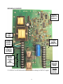
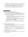
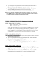
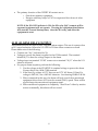
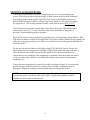
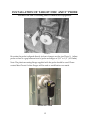
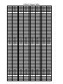
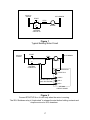
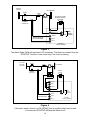
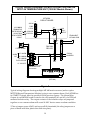
MT400 MOTION CONTROLLER INSTALLATION & TECHNICAL MANUAL 5/30/2012 417 Wards Corner Road Loveland, OH 45140 800.659.8250 FAX: 513.398.2536 www.maxitronic.com Table of Contents Page 3: Page 4: Page 5: Page 6: Page 7: Page 8: Page 9: Page 10-11: Page 12-14: Page 15: Page 16: Page 17-19: Page 20-21: Definitions MT400 PCB Layout MT400 Wiring MT400 Operation MT400 Relay Interlock Wiring Alarm Wiring Motion Sensor Probe MT400 Calibration Troubleshooting Mounting the Motion Probe 4-20mA Output Table Wiring Diagrams MT400 Installation Checklist Features: The MT400 Motion controller is an advanced underspeed detection monitor. It provides advanced equipment startup monitoring and dual-setpoint underspeed detection for 10% and 20% slowdown detection. The “target disc” is mounted on the end of the rotating shaft with the probe placed to detect the rotating targets. The EZMount probe combines target disc and sensor in a single easy to mount unit. 2 DEFINITIONS: THE FOLLOWING TERMS AND DEFINITIONS ARE PROVIDED TO AID IN UNDERSTANDING THEORY OF OPERATION, INSTALLATION PROCEDURES, AND TROUBLE SHOOTING: 1. START UP CIRCUIT: The STARTUP circuit monitors and senses the voltage when the motor is running. The function of this circuit is to start the timing circuit in the MT400 Motion Controller when the motor Start button is pressed. 2. ARM: Once the monitored equipment has successfully started and has reached 90% of full operating speed the system is said to be “ARMED” and the ARM LED will light. 2. OFFSET #1 RELAY CONTACTS: A relay rated at 5 Amps-117/240VAC. This relay is usually used to shut down auxiliary equipment (which ‘feeds’ the primary leg). It is also used to turn on an external alarm at a 10% reduction in speed. 3. OFFSET #2 RELAY CONTACTS: A relay rated at 5 Amps- 117/240VAC. This relay is usually used to shut down the primary monitored equipment (by breaking the Start button holding contacts). It can also used to turn on an external alarm at a 20% reduction in speed. 4. MOTION PROBE: The “motion probe” is a sensor mounted at the bearing or pulley that detects the speed of the equipment being monitored. A signal from the motion probe is fed to the MT400 circuit board over a low-voltage cable. 5. TARGET DISC: A 4” round disc with equally spaced metal TARGETS embedded on its edge and typically mounted to the end of a rotating shaft. The motion probe determines the speed of the shaft by detecting the targets passing in front of it. 6. MOUNTING FLANGE: is used to mount and adjust the motion probe in relation to the target disc. 8. ALM RELAY OUTPUT: ALM (Alarm function) provides a separate set of relay contacts for an alarm output. These 5A rated contacts close at 10% speed reduction. When the 10% indicator is lit the contacts are closed. 9. 4-20 MA CONFIGURATION: used to give linear 4 through 20 MA current output that is proportional to monitored equipment speed. SEE PAGE 14 for mA values. 3 MT400A LAYOUT: RIBBON CABLE TO DISPLAY 1 AMP FUSE EXTERNAL ALARM CONTACTS 117VAC* BOARD POWER MOTOR “STARTUP” VOLTAGE OFFSET RELAY #1 (90%) and #2 (80%) MOTION SENSOR PROBE * Or 240VAC for MT-400 model boards marked as being for 240VAC supply. 4 New Style WHT=BRN BLK=BLK GR/RD=BLU MT-400 WIRING CONNECTIONS 1. Power: 117VAC* is connected to “117VAC, “ACCOM”, and “EGND” on TB1. 2. Motion Sensor: Sensor is attached to the Black, Red, White, Green and Shield terminals on TB2. New style: Brown=White, Black=Black, Red/Green=Blue. Note: Minimum 120 Targets-per-minute (40 RPM with a 3-Target disc). 3. STARTUP: Motor Startup Voltage (24-240VAC max) is applied to the STARTUP-A and STARTUP-B terminals when the monitored equipment is running. The Startup voltage should be 0 (zero) when the motor Stop button is pressed. To check the Startup voltage: Connect a volt meter across STARTUP-A&B. Start the equipment and you should read the same voltage as the motor starter coil. 4. External Alarm: An external Alarm should be powered via the STARTUP-A and STARTUP-B voltage and wired through the “ALM OUTPUT RELAY” N/O contacts. TESTING: Connect 120VAC* power to the MT400 Motion Sensor board, and no power going to STARTUP-A/B (the motor Start button is NOT pressed): This will place all relay contacts and LEDs in their Alarm state: The 10% and 20% LEDs illuminate. Both OFFSET relays energize and the N/C contacts ‘open up’. The “ALM RELAY OUTPUT” N/O terminal closes. At this point you can then test the “STARTUP” circuit by applying 24-240VAC to the STARTUP-A/B terminals. The easiest way to do this is to jumper power from the board by connecting 117VAC* to STARTUP-A and AC COM to STARTUP-B. If the MT400 is already wired to the motor Start button you can just press the Start button. The board will enter the Startup cycle: The 10% and 20% LEDs turn OFF. Both of the OFFSET relays will release, the N/C contacts will ‘close’. The “ALM RELAY OUTPUT” terminals ‘open’. 3-5 seconds later the board will return to its Alarm state (provided motion was not detected at the motion probe). * Or 240VAC on MT-400 boards marked as 240VAC supply models. “Start-Up Circuit”: The typical way to wire the Startup circuit is to: o Run a conductor from the ground/common side of the starter coil to the STARTUP-B terminal. o Run another conductor from the “hot” side of the starter coil to STARTUP-A terminal. See Figure 2 5 The STARTUP-A and STARTUP-B terminals will accept voltages from 120 VAC to 240 VAC only. Any other voltage will result in motion controller not working and/or damage to motion controller. Do not use DC voltages. An Auxiliary relay may be used to obtain the proper Startup voltage – See Figure 4. If you are using a Maxi-Tronic multi-monitor [more than one motion controller in one common enclosure] the STARTUP voltages must all be 120 VAC. MT400 OPERATION 1) When the equipment starter switch is pressed: Voltage is supplied to STARTUP-A and STARTUP-B terminals. Note: This voltage should be supplied to the STARTUP terminals from the time the start switch closes [energized] until the stop switch is opened [de-energized]. Input voltage at the Startup terminals activates the MT-400 “Startup” cycle: o 10% and 20% LEDs turn OFF. o Output-1 and Output-2 relays toggle to “Run” position (N/C is closed). o “ALM RELAY OUTPUT” N/O contacts open (you may here a brief sound from the external alarm as the relay toggles). o The 3 second timer starts allowing time for equipment to start moving. o The MT400 is now monitoring for any deceleration in speed before the equipment reaches full operating speed. This feature allow the motion sensor to watch the monitored equipment during startup without relying on a fixed time limit to reach full operating speed. 2) The monitored equipment begins to move: When the motor Start button is pressed the MT400 has a 3 second timer allowing time for equipment to start moving. When motion is detected the TARGET LED on the motion sensor display will start to steadily flash ON and OFF for each target that passes by the motion sensor probe. If motion is not detected within 3 seconds then OFFSET #1 and #2 RELAYS will toggle back to their STOP position and the ARM, 10%, and 20% LED indicators will illuminate ON. 3) As the equipment accelerates to operating speed: With target light flashing you should see the meter (percent of operating speed) display start to increase. 6 Any deceleration before equipment reaches operating speed will initiate an Alarm and shutdown the equipment. When meter reaches 90% on scale, the ARM LED will light. This indicates successful equipment startup. The meter display should continue to increase until a reading of 100%. NOTE: If you notice the equipment is shut down and do not know why, look to see if the ARM LED is ON. If this LED is OFF then the equipment did not reach 90% of normal operating speed and the system did not “Arm”. OFFSET RELAY OPERATION (Equipment Interlock) OFFSET RELAY CONTACT RATING: Relay contact rating: 5 AMP at 110/240VAC. Relay contacts are “dry”. NOTE: The N/O and N/C relay contact markings on PCB and wiring diagrams indicate the state of the relays in either of the following conditions: 1) No power is applied to the circuit board. 2) Power is attached to the circuit board, Startup circuit is connected, and the monitored equipment is running. OFFSET #1 (10%) RELAY CONTACTS: The OFFSET #1 relay activates (N/C opens) when equipment reduces speed 10% below normal operating speed. The 10% LED indicates the status of the OFFSET #1 relay. When the LED is illuminated the relay is energized (N/C is open). The primary function of these contacts is to o start or stop AUXILIARY equipment (feeds to the primary equipment). o turn on an alarm. See drawings ES-400-03 & 04. OFFSET # 2 (20%) RELAY CONTACTS: The OFFSET #2 relay energizes when equipment reduces speed 20% below normal operating speed: The N/C contact opens (see drawings ES-400-2 and ES400-4). The 20% LED indicates the status of the OFFSET #2 relay. When the LED is illuminated the relay is energized (N/C is open). See drawing ES400-03. 7 The primary function of the OFFSET #2 contacts are to: o Shut down primary equipment. o Energize auxiliary relays or PLC for sequenced shut down of other equipment NOTE: If the 20% LED indicator is ON, the 20% relay (N/C) contacts will be open and equipment will not operate. Pressing the equipment Start Button will start the 3-second Startup timer, close the 20% relay, and allow the equipment to start. ALM (ALARM) RELAY OUTPUT: This function allows the user to have a separate alarm output. This set of contacts close at 10% speed reduction. When the 10% LED is ON then these contacts are closed. Please make note of the following: Contacts are “dry” and rated for 5A. Voltage to power the alarm is applied to the COM terminal. The terminal labeled N/O is then the voltage output to the alarm. Voltage input on terminal “COM” comes out on terminal “N/O” when the 10% alarm is activated. For proper alarm sequence, perform the following: 1. Use the voltage at the STARTUP-A terminal voltage to power the alarm. Connect this to the ALM COM terminal. 2. If the Start-Up voltage is 117V then use an 117V AC alarm. If Start-Up voltage is 240VAC, use a 240VAC alarm etc. See drawing ES400-03 & -04. 3. When connected in this way the alarm will only sound when monitored equipment slows down 10% from the normal (100%) speed. There will be a quick beep when monitored equipment starts. 4. When monitored equipment is completely “Shut Down” either by motion sensor or manually, this alarm will not sound. 8 MOTION SENSOR PROBE: The Motion Sensor probe is a metal detection device, it is not a proximity type sensor. This allows probe to pickup targets of both ferrous and non-ferrous metals. The motion sensor sends a pulse signal [12 VAC max] to the MT400 control as it detect MOVING metal within it’s range. The closer metal is to the probe the higher the signal level. The sensing distance usually works best between 3/8” to 1/2”. The Probe can sense metal from all sides of the tip of the probe. The installer must keep metal at least 1-1/2” away from the sides of the front half of the probe to prevent it from shielding proper operation. Maxi-Tronic motion sensor probes have greater than ½ inch sensing pickup distance. This will allow for minor wobble of the target disc. The probe could be buried in the ground and still pick up targets passed over it! There is no reason to clean built up materials and dirt from the probe.. Do not run the probe cables in with high voltage [120/440 VAC] wires. Be sure the probe cables are not wrapped around high voltage lines which turn the cable into a coil and induce noise and voltages into the probe. In new plant installations be certain there is no welding on the equipment or structures that the probes are wired to. Be sure the probe wires are not connected during construction or maintenance [welding etc]. The probe has components to protect the probe from high voltages. If you notice the probes loosing sensitivity then one or more of the fail safe components may be damaged. Improper wiring and nearby lightning can damage the probe. NOTE: Input and output wiring must be acceptable to the authority having jurisdiction and in accordance with local codes. Peripheral equipment must be suitable for the location in which used 9 MT400 MOTION CONTROLLER CALIBRATION: The Calibration (CAL) knob is used to adjust the digital display so it reads 100% when the equipment is running empty at it’s correct speed. To Adjust the MT400 display: Turn calibration control (located next to the MT400 digital display) fully clockwise. Start equipment operating. After equipment is at full operating speed; Start turning calibration control counter clockwise in small increments until % tachometer reads 100%. Note: There is a short delay between what the equipment does and what the meter displays. This delay is to take care of normal deviations of equipment operation (power fluctuations, etc.). Please allow the meter to stabilize before moving to next increment when calibrating. The knob is very sensitive, this is normal behavior. If calibration potentiometer is fully clockwise and meter does not display above 100%: There are not enough targets passing probe. The standard MT400 board is designed to detect a range of 200 to 1000 targets per minute. 1. Add evenly spaced targets to disc. Be sure that targets that are added to disc are not too close. With a 1” probe the targets should not be closer than ¾” apart. 2. If monitoring slower speeds is necessary please contact Maxi-Tronic to get a higher speed MT400 board. If calibration potentiometer is fully counter-clockwise, meter will not go below 100% There are too many targets passing the probe. 1. Remove targets , with the remaining evenly spaced on the target disc. 2. If monitoring higher speeds contact Maxi-Tronic to get slower speed MT400 board. Note: Units can be purchased to detect over-speeds and/or under-speeds. 10 If excess wobble should exist after installing the target disc on the rotating shaft, perform the following: Pull some targets partially out of the disc to even the short side up with the front of the probe. These targets are press fit and can be pulled out with pliers. If targets can not be pulled out enough then do the following: 1. Enlarge the hole in the disc center. Note: The bolt securing the disc to shaft should have a large diameter washer between bolt head and the disc. If not there, please install one before performing next step! 2. Using original bolt with a large flat washer, install disc to shaft. “Snug” the bolt so that step 3 can be performed. 3. Using rubber mallet bump disc on the high “wobble” side until the wobble ceases. 4. Tighten bolt. 5. Readjust distance between probe and target on disc. See drawing on page 11 Warning: No metal can be within 1-1/2” inches (40mm) of any side of the probe. Any metal closer than 1-1/2” inches (40mm) can cause probe to malfunction. 11 TROUBLESHOOTING 1. PROBLEM: Motion sensor shuts equipment down after approximately 3 seconds. This indicates that motion was not detected prior to the 3-second startup limit. Check to see if target light flashes On and Off when the equipment is started: If the Target light does not flash: Remove probe from mounting bracket. Move a metal target (screw driver etc.) across front of probe approximately ½ inch away from probe. The target light should flash. Go to section “Target light stays on or off” and perform checks. If Target light flashes but is erratic: Check for metal being too close to the probe. Make sure the probe is close enough (3/8”-5/8”) to the target disc. 2) PROBLEM: You are not able to start the equipment: This indicates the STARTUP circuit is not wired correctly. Or, that the Offset relays are not wired (interlocked) correctly. Verify the STARTUP voltage across Startup A and B terminals. 120VAC when the motor Start button is pressed, 0 when Stop is pressed. Verify the OFFSET #2 (20%) relay is wired correctly (interlocked) to the Start button holding contacts on the motor starter. See wiring diagrams at the end of this manual. 3) PROBLEM: Motion sensor will not allow auxiliary equipment connected to MT400 motion controller to operate: OFFSET #1 (10%) relay contacts are not correctly wired (interlocked). See wiring diagrams at the end of this manual. 4) PROBLEM: Target light stays on or off at all times when equipment is started. Check the following: A) Motion sensor cable not connected properly. Check at motion sensor terminal for the following: a) Match wire colors from Probe cable to the MT400 terminal strip label. 12 b) Check all connections and splices for breaks and shorts. c) Clean the connector in plug-type Probes. d) Check continuity of the cable. Disconnect wires at motion Probe and from the MT400 circuit board. Twist any 2 wires together and verify continuity at the other end. Repeat for the other two wires. Note: If equipment is started and motion sensor allows equipment to operate and tachometer display increases and all other motion sensor functions seem correct then check target indicator. This is a LED and will normally last the life of motion sensor control. Check for broken leads or a lead shorted to housing. Repair or replace as needed. 5) Testing MT400 Circuit Board Operation: Remove either the Black or the White wire and tap it to it's terminal to simulate a target signal. You should be able to bring the meter up to 100% doing this. 13 Additional Troubleshooting: Check Probe and MT400 voltages: NOTE: New style sensor: Brown=White, Black=Black, Red/Green=Blue 1) Motion Probe VOLTS test: Perform this test with the probe wires attached to MT400 circuit board. Note: The Green and Red wires are both Ground. Black wire to probe Green (or Red) should read between 4-7 VDC. A broken black wire will cause 12 VDC to be read at the black terminal. White wire to Green (or Red) should read 12 VDC. 2) Motion Probe OHMS test: Disconnect the probe wires from the MT400 board before OHMS testing. Touch all the probe wires together (to drain the internal capacitors) before running each Ohms test below. Note: The Green and Red wires are both Ground. Don't hold the wires in your fingers when Ohms testing, this will affect readings. A good ohms reading does not guarantee that the probe is good. BLACK-to-GREEN=20K Ohms. Measure between the Black wire (using the positive lead on the Ohm meter) and the Green wire (using the negative lead on the Ohm meter) should be around 20K ohms. WHITE-to-GREEN=3M Ohms. Measure between the White wire (using the positive lead on the ohm meter) and Green wire (using the negative lead) will start around 3Meg ohm, and may climb off scale to infinity. BLACK-to-WHITE=3M Ohms. Measure between the Black wire (using positive lead on the ohm meter) and White wire (negative lead) is around 3Meg ohm. WHITE-to-BLACK=3M Ohms. Reverse the leads from the last test: Measure between Black wire (using negative lead of ohm meter) and White wire (using positive lead) will start around 3Meg ohm and may climb off scale to infinity (open circuit). 14 INSTALLATION OF TARGET DISC AND 1” PROBE Mounted on end of rotating shaft of monitored equipment. Photo 1 Be certain the probe is aligned directly in front of targets on disc (see Photo 1). Adjust probe so there is a gap between front of probe and targets of 3/8” to 1/2” (10-13mm). Note: The plastic mounting flange supplied with the probe should be used. Please contact Maxi-Tronic if other flanges will be used or modifications are made. EZMount Probe 15 4-20mA Output Table % 0 1 2 3 4 5 6 7 8 9 10 11 12 13 14 15 16 17 18 19 20 21 22 23 24 25 26 27 28 29 30 31 32 33 34 35 36 37 38 39 40 41 42 43 44 45 46 47 48 49 mA 4.00 4.08 4.16 4.24 4.32 4.40 4.48 4.56 4.64 4.72 4.80 4.88 4.96 5.04 5.12 5.20 5.28 5.36 5.44 5.52 5.60 5.68 5.76 5.84 5.92 6.00 6.08 6.16 6.24 6.32 6.40 6.48 6.56 6.64 6.72 6.80 6.88 6.96 7.04 7.12 7.20 7.28 7.36 7.44 7.52 7.60 7.68 7.76 7.84 7.92 % 50 51 52 53 54 55 56 57 58 59 60 61 62 63 64 65 66 67 68 69 70 71 72 73 74 75 76 77 78 79 80 81 82 83 84 85 86 87 88 89 90 91 92 93 94 95 96 97 98 99 mA 8.00 8.08 8.16 8.24 8.32 8.40 8.48 8.56 8.64 8.72 8.80 8.88 8.96 9.04 9.12 9.20 9.28 9.36 9.44 9.52 9.60 9.68 9.76 9.84 9.92 10.00 10.08 10.16 10.24 10.32 10.40 10.48 10.56 10.64 10.72 10.80 10.88 10.96 11.04 11.12 11.20 11.28 11.36 11.44 11.52 11.60 11.68 11.76 11.84 11.92 % 100 101 102 103 104 105 106 107 108 109 110 111 112 113 114 115 116 117 118 119 120 121 122 123 124 125 126 127 128 129 130 131 132 133 134 135 136 137 138 139 140 141 142 143 144 145 146 147 148 149 mA 12.00 12.08 12.16 12.24 12.32 12.40 12.48 12.56 12.64 12.72 12.80 12.88 12.96 13.04 13.12 13.20 13.28 13.36 13.44 13.52 13.60 13.68 13.76 13.84 13.92 14.00 14.08 14.16 14.24 14.32 14.40 14.48 14.56 14.64 14.72 14.80 14.88 14.96 15.04 15.12 15.20 15.28 15.36 15.44 15.52 15.60 15.68 15.76 15.84 15.92 % 150 151 152 153 154 155 156 157 158 159 160 161 162 163 164 165 166 167 168 169 170 171 172 173 174 175 176 177 178 179 180 181 182 183 184 185 186 187 188 189 190 191 192 193 194 195 196 197 198 199 200 mA 16.00 16.08 16.16 16.24 16.32 16.40 16.48 16.56 16.64 16.72 16.80 16.88 16.96 17.04 17.12 17.20 17.28 17.36 17.44 17.52 17.60 17.68 17.76 17.84 17.92 18.00 18.08 18.16 18.24 18.32 18.40 18.48 18.56 18.64 18.72 18.80 18.88 18.96 19.04 19.12 19.20 19.28 19.36 19.44 19.52 19.60 19.68 19.76 19.84 19.92 20.00 24VAC to 240VAC AC COMMON START STOP MOTOR M HOLDING CONTACTS Figure 1 Typical Existing Motor Circuit 24VAC to 240VAC START AC COMMON STOP MOTOR M HOLDING CONTACTS STARTUP-B STARTUP-A COM-2 OFFSET RELAY #2 (20% SHUTDOWN) N/O-2 N/C-2 MT-400A CIRCUIT BOARD Figure 2 Connect STARTUP-A so it is hot only when the motor is running. The 20% Shutdown relay is “interlocked” to release the start button holding contacts and stop the motor at a 20% slowdown. 17 24VAC to 240VAC AC COMMON START STOP 24-240VAC ALARM (SAME AS MOTOR STARTER) MOTOR M HOLDING CONTACTS STARTUP-B COM ALM RELAY N/O OUTPUT STARTUP-A COM-2 OFFSET RELAY #2 (20% SHUTDOWN) N/O-2 N/C-2 MT-400A CIRCUIT BOARD Figure 3 The Alarm Relay (ALM) will operate at 10% slowdown. The Alarm is powered from the “STARTUP” circuit so it can sound only if the motor is running. 250V MAX STARTER VOLTAGE START STOP AC COMMON MOTOR M 120VAC* ALARM HOLDING CONTACTS AUX RELAY ACCOM EGND 117VAC* STARTUP-B STARTUP-A COM-2 OFFSET RELAY #2 (20% SHUTDOWN) COM ALM RELAY N/O OUTPUT N/O-2 N/C-2 MT-400A CIRCUIT BOARD Figure 4 If the motor starter circuit is not 24-240VAC then an auxiliary relay can be used to connect the STARTUP-A/B and the Alarm circuit. 18 TYPICAL WIRING DIAGRAM FOR MULTIPLE MOTION AND AN MTDT-24 TEMPERATURE UNIT (120VAC Models Shown) TB1 MT-400A CIRCUIT BOARD ACCOM EGND AC COMMON FROM MOTOR STARTER CIRCUIT 120VAC FROM MOTOR STARTER CIRCUIT TB2 117VAC COM STARUP-B N/O STARTUP-A ALM RELAY OUTPUT FROM NEXT MT-400A PCB A1 A1 A1 A2 A2 A2 DIN RAIL RELAYS 117VAC ALARM ALARM OUT 117V ALARM TS1 11 AC COMMON 14 AC COMMON 11 14 (N/O) 12 11 * RELAY JUMPERS 14 12 12 NOT USED EARTH GROUND 117 VAC INPUT POWER TERMINAL STRIP LOCATED IN MULTIPLE UNIT HOUSING HI-TEMP TRIP (N/O) 117 AC VAC COM MTDT-24 UNIT (OPTIONAL) Figure 5 Typical wiring diagram showing multiple MT-400 motion sensors (and an option MTDT24 Hazard Temperature Monitor) going to one common alarm. Each MT400 has its STARTUP circuit wired as specified on the previous figures. The Alarm Relay Output of each MT400 board is wired to the coil terminals (A1 and A2) of a DIN-rail mounted isolation relay. The output contacts of the isolation relays are jumpered together so one common alarm will sound if ANY device senses an alarm condition. * Place a jumper across all #11 and across all #14 terminals (the relay jumpers are a piece of metal with blue plastic that slide into place). 19 MT400 MOTION CONTROLLER AND SENSOR TEST PROCEDURE CHECKLIST Complete the following procedures after installing or replacing any equipment to ensure the system is fully operational and protecting your equipment. Complete one checklist for each Motion Controller. IMPORTANT: The motion sensor probe is a metal detection device. ANY metal within 1-1/2” of the probe will degrade performance. To Test MT400 Motion Controllers and sensors In The Field: 1. Start monitored equipment to operating speed with NO load on it (running empty). Confirm that the monitored shaft RPM is running at the manufacturer specifications. Manufacturer specified RPM____________ Field Test RPM ___________ 2. Check motion sensor for the following: Target indicator should flash steadily for each target that passes by the probe. Percent meter should gradually increase then read approximately 100%. The Arm Indicator should become lit. 10% Indicator should not be lit. 20% Indicator should not be lit. 3. Turn the calibration knob fully counter-clockwise and check for the following: Percent meter reading should start to drop (decrease). When percent meter drops (decreases) below 90%: 10% Indicator will turn ON If an Alarm is installed, the alarm should now be energized and sound. Any equipment connected to the 10% relay for shut down will shut down. When percent meter drops (decreases) below 80%: 20% Indicator will turn ON. Equipment connected for shut down at 20% reduction of speed will shut down and alarm will shut off. 20 4. Recalibrate Motion Controller: Turn calibration knob fully clockwise. Start monitored equipment to operating speed WITHOUT LOAD. Percent meter should go above 100%. Slowly turn calibration knob counter-clockwise until percent meter reads 100%. 5. Verify equipment under load Reconfirm Field Test RPM: ___________ under full load capacity. 6. MT400 Motion sensor is now ready for normal operation. NOTE: IF ANY STEP IN THIS TEST PROCEDURE DOES NOT OCCUR AS NOTED, PLEASE CONTACT MAXI-TRONIC AT 800-659-8250. Date: _________________________________ Facility Name: _________________________________ Location: _________________________________ Leg Name: _________________________________ Installer: _________________________________ Tested by: _________________________________ To register this MT Motion Controller for warranty please fax a copy of this completed checklist to Maxi-Tronic, Inc. at 513-398-2536. Complete one checklist for each MT400 Controller. 21